EP3747546B1 - Anordnung, instrument zur durchführung einer temperaturabhängigen reaktion und verfahren zur durchführung einer temperaturabhängigen reaktion in einer anordnung - Google Patents
Anordnung, instrument zur durchführung einer temperaturabhängigen reaktion und verfahren zur durchführung einer temperaturabhängigen reaktion in einer anordnung Download PDFInfo
- Publication number
- EP3747546B1 EP3747546B1 EP20188220.6A EP20188220A EP3747546B1 EP 3747546 B1 EP3747546 B1 EP 3747546B1 EP 20188220 A EP20188220 A EP 20188220A EP 3747546 B1 EP3747546 B1 EP 3747546B1
- Authority
- EP
- European Patent Office
- Prior art keywords
- thermo electric
- electrodeposited
- assembly
- electric element
- heat sink
- Prior art date
- Legal status (The legal status is an assumption and is not a legal conclusion. Google has not performed a legal analysis and makes no representation as to the accuracy of the status listed.)
- Active
Links
- 238000006243 chemical reaction Methods 0.000 title claims description 26
- 230000001419 dependent effect Effects 0.000 title claims description 22
- 238000000034 method Methods 0.000 title claims description 15
- 238000001816 cooling Methods 0.000 claims description 14
- 238000010438 heat treatment Methods 0.000 claims description 8
- 239000000853 adhesive Substances 0.000 claims description 5
- 230000001070 adhesive effect Effects 0.000 claims description 5
- 239000003550 marker Substances 0.000 description 21
- 239000012491 analyte Substances 0.000 description 12
- 230000003287 optical effect Effects 0.000 description 10
- 230000005284 excitation Effects 0.000 description 9
- 238000004880 explosion Methods 0.000 description 8
- 239000000463 material Substances 0.000 description 8
- 238000004070 electrodeposition Methods 0.000 description 7
- 239000012530 fluid Substances 0.000 description 6
- 239000000919 ceramic Substances 0.000 description 5
- 238000001514 detection method Methods 0.000 description 5
- 239000004065 semiconductor Substances 0.000 description 5
- 230000005540 biological transmission Effects 0.000 description 4
- 238000013461 design Methods 0.000 description 4
- 239000007788 liquid Substances 0.000 description 4
- 239000000758 substrate Substances 0.000 description 4
- 230000003321 amplification Effects 0.000 description 3
- 239000003153 chemical reaction reagent Substances 0.000 description 3
- 150000001875 compounds Chemical class 0.000 description 3
- 238000010276 construction Methods 0.000 description 3
- 230000000694 effects Effects 0.000 description 3
- 230000014509 gene expression Effects 0.000 description 3
- 239000003292 glue Substances 0.000 description 3
- 238000003199 nucleic acid amplification method Methods 0.000 description 3
- 239000002245 particle Substances 0.000 description 3
- 238000012546 transfer Methods 0.000 description 3
- 238000003556 assay Methods 0.000 description 2
- 239000008280 blood Substances 0.000 description 2
- 210000004369 blood Anatomy 0.000 description 2
- 239000011248 coating agent Substances 0.000 description 2
- 238000000576 coating method Methods 0.000 description 2
- 238000005516 engineering process Methods 0.000 description 2
- 230000004907 flux Effects 0.000 description 2
- 238000004020 luminiscence type Methods 0.000 description 2
- 238000004519 manufacturing process Methods 0.000 description 2
- 150000007523 nucleic acids Chemical class 0.000 description 2
- 102000039446 nucleic acids Human genes 0.000 description 2
- 108020004707 nucleic acids Proteins 0.000 description 2
- 230000036316 preload Effects 0.000 description 2
- 239000000376 reactant Substances 0.000 description 2
- XSOKHXFFCGXDJZ-UHFFFAOYSA-N telluride(2-) Chemical compound [Te-2] XSOKHXFFCGXDJZ-UHFFFAOYSA-N 0.000 description 2
- 238000012360 testing method Methods 0.000 description 2
- 206010003445 Ascites Diseases 0.000 description 1
- RYGMFSIKBFXOCR-UHFFFAOYSA-N Copper Chemical compound [Cu] RYGMFSIKBFXOCR-UHFFFAOYSA-N 0.000 description 1
- 230000005679 Peltier effect Effects 0.000 description 1
- 210000004381 amniotic fluid Anatomy 0.000 description 1
- 210000003567 ascitic fluid Anatomy 0.000 description 1
- 230000015572 biosynthetic process Effects 0.000 description 1
- 229910052797 bismuth Inorganic materials 0.000 description 1
- JCXGWMGPZLAOME-UHFFFAOYSA-N bismuth atom Chemical compound [Bi] JCXGWMGPZLAOME-UHFFFAOYSA-N 0.000 description 1
- 210000004027 cell Anatomy 0.000 description 1
- 238000005119 centrifugation Methods 0.000 description 1
- 210000001175 cerebrospinal fluid Anatomy 0.000 description 1
- 239000007795 chemical reaction product Substances 0.000 description 1
- 238000007820 coagulation assay Methods 0.000 description 1
- 230000000295 complement effect Effects 0.000 description 1
- 239000002826 coolant Substances 0.000 description 1
- 229910052802 copper Inorganic materials 0.000 description 1
- 239000010949 copper Substances 0.000 description 1
- 239000013078 crystal Substances 0.000 description 1
- 238000005520 cutting process Methods 0.000 description 1
- 230000001351 cycling effect Effects 0.000 description 1
- 230000009089 cytolysis Effects 0.000 description 1
- 238000007865 diluting Methods 0.000 description 1
- 238000004821 distillation Methods 0.000 description 1
- 239000000975 dye Substances 0.000 description 1
- 230000005684 electric field Effects 0.000 description 1
- 238000001962 electrophoresis Methods 0.000 description 1
- 238000001652 electrophoretic deposition Methods 0.000 description 1
- 238000001914 filtration Methods 0.000 description 1
- 238000000265 homogenisation Methods 0.000 description 1
- 238000005286 illumination Methods 0.000 description 1
- 238000003018 immunoassay Methods 0.000 description 1
- 230000002779 inactivation Effects 0.000 description 1
- 230000002452 interceptive effect Effects 0.000 description 1
- 238000012423 maintenance Methods 0.000 description 1
- 238000005259 measurement Methods 0.000 description 1
- 229910052751 metal Inorganic materials 0.000 description 1
- 239000002184 metal Substances 0.000 description 1
- 150000002739 metals Chemical class 0.000 description 1
- 210000004080 milk Anatomy 0.000 description 1
- 239000008267 milk Substances 0.000 description 1
- 235000013336 milk Nutrition 0.000 description 1
- 239000000203 mixture Substances 0.000 description 1
- 238000010422 painting Methods 0.000 description 1
- 239000000049 pigment Substances 0.000 description 1
- 238000007747 plating Methods 0.000 description 1
- 229920000642 polymer Polymers 0.000 description 1
- 238000003752 polymerase chain reaction Methods 0.000 description 1
- 238000003825 pressing Methods 0.000 description 1
- 239000002994 raw material Substances 0.000 description 1
- 210000003296 saliva Anatomy 0.000 description 1
- 238000005476 soldering Methods 0.000 description 1
- 239000007787 solid Substances 0.000 description 1
- 239000000126 substance Substances 0.000 description 1
- 239000000725 suspension Substances 0.000 description 1
- 210000004243 sweat Anatomy 0.000 description 1
- 210000001179 synovial fluid Anatomy 0.000 description 1
- 210000001519 tissue Anatomy 0.000 description 1
- 210000002700 urine Anatomy 0.000 description 1
Images


Classifications
-
- B—PERFORMING OPERATIONS; TRANSPORTING
- B01—PHYSICAL OR CHEMICAL PROCESSES OR APPARATUS IN GENERAL
- B01L—CHEMICAL OR PHYSICAL LABORATORY APPARATUS FOR GENERAL USE
- B01L7/00—Heating or cooling apparatus; Heat insulating devices
- B01L7/52—Heating or cooling apparatus; Heat insulating devices with provision for submitting samples to a predetermined sequence of different temperatures, e.g. for treating nucleic acid samples
-
- G—PHYSICS
- G01—MEASURING; TESTING
- G01N—INVESTIGATING OR ANALYSING MATERIALS BY DETERMINING THEIR CHEMICAL OR PHYSICAL PROPERTIES
- G01N21/00—Investigating or analysing materials by the use of optical means, i.e. using sub-millimetre waves, infrared, visible or ultraviolet light
- G01N21/01—Arrangements or apparatus for facilitating the optical investigation
-
- B—PERFORMING OPERATIONS; TRANSPORTING
- B01—PHYSICAL OR CHEMICAL PROCESSES OR APPARATUS IN GENERAL
- B01L—CHEMICAL OR PHYSICAL LABORATORY APPARATUS FOR GENERAL USE
- B01L3/00—Containers or dishes for laboratory use, e.g. laboratory glassware; Droppers
- B01L3/50—Containers for the purpose of retaining a material to be analysed, e.g. test tubes
- B01L3/508—Containers for the purpose of retaining a material to be analysed, e.g. test tubes rigid containers not provided for above
- B01L3/5085—Containers for the purpose of retaining a material to be analysed, e.g. test tubes rigid containers not provided for above for multiple samples, e.g. microtitration plates
-
- B—PERFORMING OPERATIONS; TRANSPORTING
- B01—PHYSICAL OR CHEMICAL PROCESSES OR APPARATUS IN GENERAL
- B01L—CHEMICAL OR PHYSICAL LABORATORY APPARATUS FOR GENERAL USE
- B01L9/00—Supporting devices; Holding devices
- B01L9/06—Test-tube stands; Test-tube holders
-
- C—CHEMISTRY; METALLURGY
- C12—BIOCHEMISTRY; BEER; SPIRITS; WINE; VINEGAR; MICROBIOLOGY; ENZYMOLOGY; MUTATION OR GENETIC ENGINEERING
- C12P—FERMENTATION OR ENZYME-USING PROCESSES TO SYNTHESISE A DESIRED CHEMICAL COMPOUND OR COMPOSITION OR TO SEPARATE OPTICAL ISOMERS FROM A RACEMIC MIXTURE
- C12P19/00—Preparation of compounds containing saccharide radicals
- C12P19/26—Preparation of nitrogen-containing carbohydrates
- C12P19/28—N-glycosides
- C12P19/30—Nucleotides
- C12P19/34—Polynucleotides, e.g. nucleic acids, oligoribonucleotides
-
- G—PHYSICS
- G01—MEASURING; TESTING
- G01N—INVESTIGATING OR ANALYSING MATERIALS BY DETERMINING THEIR CHEMICAL OR PHYSICAL PROPERTIES
- G01N21/00—Investigating or analysing materials by the use of optical means, i.e. using sub-millimetre waves, infrared, visible or ultraviolet light
- G01N21/62—Systems in which the material investigated is excited whereby it emits light or causes a change in wavelength of the incident light
- G01N21/63—Systems in which the material investigated is excited whereby it emits light or causes a change in wavelength of the incident light optically excited
- G01N21/64—Fluorescence; Phosphorescence
- G01N21/6402—Atomic fluorescence; Laser induced fluorescence
-
- G—PHYSICS
- G01—MEASURING; TESTING
- G01N—INVESTIGATING OR ANALYSING MATERIALS BY DETERMINING THEIR CHEMICAL OR PHYSICAL PROPERTIES
- G01N21/00—Investigating or analysing materials by the use of optical means, i.e. using sub-millimetre waves, infrared, visible or ultraviolet light
- G01N21/62—Systems in which the material investigated is excited whereby it emits light or causes a change in wavelength of the incident light
- G01N21/63—Systems in which the material investigated is excited whereby it emits light or causes a change in wavelength of the incident light optically excited
- G01N21/64—Fluorescence; Phosphorescence
- G01N21/6486—Measuring fluorescence of biological material, e.g. DNA, RNA, cells
-
- H—ELECTRICITY
- H01—ELECTRIC ELEMENTS
- H01L—SEMICONDUCTOR DEVICES NOT COVERED BY CLASS H10
- H01L23/00—Details of semiconductor or other solid state devices
- H01L23/34—Arrangements for cooling, heating, ventilating or temperature compensation ; Temperature sensing arrangements
- H01L23/38—Cooling arrangements using the Peltier effect
-
- H—ELECTRICITY
- H05—ELECTRIC TECHNIQUES NOT OTHERWISE PROVIDED FOR
- H05B—ELECTRIC HEATING; ELECTRIC LIGHT SOURCES NOT OTHERWISE PROVIDED FOR; CIRCUIT ARRANGEMENTS FOR ELECTRIC LIGHT SOURCES, IN GENERAL
- H05B1/00—Details of electric heating devices
- H05B1/02—Automatic switching arrangements specially adapted to apparatus ; Control of heating devices
- H05B1/0227—Applications
- H05B1/023—Industrial applications
- H05B1/0247—For chemical processes
-
- H—ELECTRICITY
- H05—ELECTRIC TECHNIQUES NOT OTHERWISE PROVIDED FOR
- H05B—ELECTRIC HEATING; ELECTRIC LIGHT SOURCES NOT OTHERWISE PROVIDED FOR; CIRCUIT ARRANGEMENTS FOR ELECTRIC LIGHT SOURCES, IN GENERAL
- H05B3/00—Ohmic-resistance heating
- H05B3/10—Heater elements characterised by the composition or nature of the materials or by the arrangement of the conductor
-
- H—ELECTRICITY
- H10—SEMICONDUCTOR DEVICES; ELECTRIC SOLID-STATE DEVICES NOT OTHERWISE PROVIDED FOR
- H10N—ELECTRIC SOLID-STATE DEVICES NOT OTHERWISE PROVIDED FOR
- H10N10/00—Thermoelectric devices comprising a junction of dissimilar materials, i.e. devices exhibiting Seebeck or Peltier effects
- H10N10/10—Thermoelectric devices comprising a junction of dissimilar materials, i.e. devices exhibiting Seebeck or Peltier effects operating with only the Peltier or Seebeck effects
- H10N10/17—Thermoelectric devices comprising a junction of dissimilar materials, i.e. devices exhibiting Seebeck or Peltier effects operating with only the Peltier or Seebeck effects characterised by the structure or configuration of the cell or thermocouple forming the device
-
- H—ELECTRICITY
- H10—SEMICONDUCTOR DEVICES; ELECTRIC SOLID-STATE DEVICES NOT OTHERWISE PROVIDED FOR
- H10N—ELECTRIC SOLID-STATE DEVICES NOT OTHERWISE PROVIDED FOR
- H10N19/00—Integrated devices, or assemblies of multiple devices, comprising at least one thermoelectric or thermomagnetic element covered by groups H10N10/00 - H10N15/00
-
- B—PERFORMING OPERATIONS; TRANSPORTING
- B01—PHYSICAL OR CHEMICAL PROCESSES OR APPARATUS IN GENERAL
- B01L—CHEMICAL OR PHYSICAL LABORATORY APPARATUS FOR GENERAL USE
- B01L2200/00—Solutions for specific problems relating to chemical or physical laboratory apparatus
- B01L2200/02—Adapting objects or devices to another
- B01L2200/025—Align devices or objects to ensure defined positions relative to each other
-
- B—PERFORMING OPERATIONS; TRANSPORTING
- B01—PHYSICAL OR CHEMICAL PROCESSES OR APPARATUS IN GENERAL
- B01L—CHEMICAL OR PHYSICAL LABORATORY APPARATUS FOR GENERAL USE
- B01L2300/00—Additional constructional details
- B01L2300/08—Geometry, shape and general structure
- B01L2300/0809—Geometry, shape and general structure rectangular shaped
- B01L2300/0829—Multi-well plates; Microtitration plates
-
- B—PERFORMING OPERATIONS; TRANSPORTING
- B01—PHYSICAL OR CHEMICAL PROCESSES OR APPARATUS IN GENERAL
- B01L—CHEMICAL OR PHYSICAL LABORATORY APPARATUS FOR GENERAL USE
- B01L2300/00—Additional constructional details
- B01L2300/18—Means for temperature control
- B01L2300/1805—Conductive heating, heat from thermostatted solids is conducted to receptacles, e.g. heating plates, blocks
- B01L2300/1822—Conductive heating, heat from thermostatted solids is conducted to receptacles, e.g. heating plates, blocks using Peltier elements
-
- B—PERFORMING OPERATIONS; TRANSPORTING
- B01—PHYSICAL OR CHEMICAL PROCESSES OR APPARATUS IN GENERAL
- B01L—CHEMICAL OR PHYSICAL LABORATORY APPARATUS FOR GENERAL USE
- B01L2300/00—Additional constructional details
- B01L2300/18—Means for temperature control
- B01L2300/1894—Cooling means; Cryo cooling
Definitions
- the present invention relates to an assembly, to an instrument for performing one or more temperature-dependent reactions and to a method for performing a temperature-dependent reaction in an assembly.
- An assembly in the sense of the present invention comprises a sample block, a heat sink and at least one thermo electric element.
- a sample block is configured to receive at least one and preferably a plurality of sample vessels.
- the thermo electric element is designed as a thermo electric cooler or a thermoelectric heater.
- a thermo electric cooler uses the Peltier effect to create a heat flux between the junction of two different types of materials.
- a Peltier cooler, heater, or thermoelectric heat pump is a solid-state active heat pump which transfers heat from one side of the device to the other, depending on the direction of the current, with consumption of electrical energy.
- Such an instrument is also called a Peltier device, Peltier heat pump, solid state refrigerator, or thermo electric cooler. It can be used either for heating or for cooling, although in practice the main application is cooling.
- thermoelectric element and the heat sink allow controlled temperature cycles to be applied to a sample for polymerase chain reaction, which is thereby amplified.
- thermo electric element and the heat sink allow the detection of a light reaction when excitation light is applied to the sample.
- thermo electric elements with ceramics as a substrate are widespread and commonly used. Such thermo electric elements are described in US 2008/0308140 A1 .
- US 2011/312102 A1 discloses a light transmissive temperature control apparatus comprising a thermoelectric block.
- WO 2005/0413 14 A2 describes a thermoelectric device, comprising a first heat conducting layer having a cold pole and a second heat conducting layer substantially devoid of a hot pole, the first and the second heat conducting layers being interposed by at least one semiconductor layer, being under a potential difference.
- thermo electric element provides advantages concerning the handling within such an assembly. Nevertheless, there are still some drawbacks. Particularly, the tolerance for building openings or holes into thermo electric elements with ceramics as a substrate is strongly limited. Mounting and fixing takes place between different thermo electric elements resulting in a minimum distance between them. Further, said ceramics substrate is typically planar. They need to be strongly pre-stressed and assembled in a thermal sandwich using a thermal interface material. A thermal interface material is needed because their structure is very rigid.
- standard thermo electric elements further provide homogeneous power density due to fixed distances between semiconductor legs. The semiconductor legs are produced by cutting the required block sizes from a e.g.
- thermo electric element assembly always shows thermal edge-effects and corner-effects concerning homogeneity of temperature, caused by varying thermal loss due to cold neighborhood and limiting homogenization capacity of heated / cooled interface platen.
- the terms “have”, “comprise” or “include” or any arbitrary grammatical variations thereof are used in a non-exclusive way. Thus, these terms may both refer to a situation in which, besides the feature introduced by these terms, no further features are present in the entity described in this context and to a situation in which one or more further features are present.
- the expressions “A has B”, “A comprises B” and “A includes B” may both refer to a situation in which, besides B, no other element is present in A (i.e. a situation in which A solely and exclusively consists of B) and to a situation in which, besides B, one or more further elements are present in entity A, such as element C, elements C and D or even further elements.
- the terms "at least one”, “one or more” or similar expressions indicating that a feature or element may be present once or more than once typically will be used only once when introducing the respective feature or element.
- the expressions “at least one” or “one or more” will not be repeated, non-withstanding the fact that the respective feature or element may be present once or more than once.
- An assembly comprising a sample block, a heat sink and at least one electro-deposited thermo electric element.
- Production technology of electro-deposited thermo electric elements allows for any customized shape such as multiply perforated or recessed thermo electric elements without loss of applicable power per area.
- Electro-deposited thermo electric elements can also be made flexible. They can be brought into many shapes like cylinders or cones. Thus, the production technology of electro-deposited thermo electric elements allows nearly any thinkable order, shape, layout and size of the particles such as telluride crystals and therefore even makes it possible to provide certain power compensation near the edges and corners.
- the electrodeposited thermo electric element may be disposed between the sample block and the heat sink. Thus, heat may be removed from the sample block and transferred to the heat sink.
- the electrodeposited thermo electric element may contact the sample block and/or the heat sink. Thus, a direct heat transmission from the electrodeposited thermo electric element to the sample block and/or the heat sink and vice versa is provided.
- the sample block may be fixed to the electrodeposited thermo electric element and the heat sink.
- a shift of the sample block relative to the electrodeposited thermo electric element and the heat sink is prevented. Therefore, the orientation of these constructional members permanently remains the same such the heat flux between these constructional members may be reliably controlled.
- the sample block may be fixed to the electrodeposited thermo electric element and the heat sink by means of a positive fit connection and/or a non-positive fit connection and/or an adhesive bond connection.
- the adhesive bond connection may be provided by using a thermally stable and thermal conducting glue.
- the sample block may comprise at least one fixture bolt.
- the electrodeposited thermo electric element may comprise at least one fixture hole and the heat sink may comprise at least one fixture hole.
- At least one threaded bolt may engage the fixture hole of the thermo electric element and the fixture hole of the heat sink.
- the sample block may comprise one or more recesses each configured to receive a sample vessel.
- the shape of said at least one electrodeposited thermoelectric element may be adapted to the shape of said one or more recesses.
- Using such shaped electrodeposited thermoelectric elements makes it easy to produce directly cooled sample mounts or racks or pucks.
- the electrodeposited thermoelectric element(s) may be provided as a curved electrodeposited thermoelectric element around a collar of the mount(s).
- the sample block comprises at least one recess configured to receive a sample vessel.
- the recess comprises at its bottom end, a through hole.
- the electrodeposited thermo electric element comprises least one through hole.
- the heat sink comprises at least one through hole. The through hole of the recess, the through hole of the electro-deposited thermo electric cooling element and the through hole of the heat sink are aligned on a common axis. Thus, an optical path is provided through which light may propagate and be detected.
- the recess may be tapered towards the electrodeposited thermo electric element.
- the thermal interface may be realized in a tapered shape so that pre-load may be realized by reduced spring load and reduced tolerance specifications or for a radial thermal interface where height is a critical design parameter.
- the recess may be conically shaped.
- the thermal interface may be realized in a conic shape so that pre-load may be realized by reduced spring load and reduced tolerance specifications or for a radial thermal interface where height is a critical design parameter.
- the electrodeposited thermo electric element may comprise thermo electric zones.
- the zones are individually operable. Thus, the zones are operable independent on one another. Thus, different heating and/or cooling performances are provided between the respective zones.
- thermo electric zones may comprise identical or different cooling power or heating power characteristics. Particularly, different zones can be built insulated from each other so that they can be powered independently and differently. That way, thermal homogeneity and/or various ramp or cycling profiles can be reached in one single hardware setup.
- thermo electric zones may comprise sub-portions.
- the sub-portions may comprise identical or different cooling power or heating power characteristics.
- zones may be divided themselves into sub-portions allowing smaller areas of individual heat transmission.
- areas or sub-portions with different power characteristics can be implemented to compensate edge effects or design related asymmetries.
- the electrodeposited thermo electric element may basically comprise a planar, ashlar-formed, cylindrical, conical, polygonal, or polygonal with rounded edges shape, polyhedric, polyhedric with rounded edges, or any three dimensional form.
- the electro-deposited thermo electric element may be designed in a plurality of potential shapes. Accordingly, thermo electric elements made by electrodeposition may be individually shaped with rather low effort.
- An instrument for performing a temperature-dependent reaction comprising an assembly as described above and at least one laboratory device.
- the assembly may be well integrated into different kinds of laboratory instruments.
- a method of performing a temperature-dependent reaction in an assembly as described above or an instrument as described above comprises exposing a sample comprised in a sample vessel disposed in a recess of a sample block to one or more specified temperatures by operating the electrodeposited thermo electric element.
- the temperature-dependent reaction may be controlled in an improved and simplified manner.
- the electrodeposited thermo electric element may be operated so as to cool and/or heat the sample in the sample vessel.
- the temperature within the sample vessel may be controlled by supplying heat to the sample vessel or removing heat from the sample vessel.
- a method of determining the presence or absence of an analyte in a sample comprising performing the method described above in the presence of a detectable marker which is specific for said analyte, and detecting light emitted by said detectable marker which is indicative of the presence or absence of said analyte.
- the marker may be a fluorophore or an electrochemiluminescent compound.
- well established markers may be used with the method.
- the marker may be a fluorophore
- the sample may be exposed to excitation light during and / or after said temperature-dependent reaction and emitted light may be detected by a detector, wherein said emitted light is indicative for the presence of said analyte.
- the analyte may be reliably detected with improved temperature-dependent reaction kinetics.
- An excitation light source may be located above the sample block and a detector may be located below the heat sink of the assembly as described above. Thus, the light originating from the sample may be reliably detected in a simple manner.
- sample block refers to a block shaped constructional member comprising chambers or recesses configured to accommodate sample vessel.
- the sample vessels may be plastic vessels. Particularly, the sample vessels may be constructed and arranged to permit an optimal heat transfer between the block and a liquid sample comprised within said vessels. This allows for optimal conditions during or after thermocycling and ensures specificity and efficiency of the nucleic acid amplification.
- the liquid comprises reactants which can be detected by illumination with light beams. Examples of reactants are fluorescent labels which correlate with the formation of a reaction product in the liquid.
- a reaction is an amplification reaction, such as TMA, NASBA or PCR. Such amplification reactions are well known in the art.
- the sample vessels are multi well plates, i.e. wells arranged in a microtiter plate.
- heat sink refers to a passive heat exchanger that transfers the heat generated by an electronic or a mechanical device into a coolant fluid in motion. The transferred heat leaves the device with the fluid in motion, therefore allowing the regulation of the device temperature at physically feasible levels.
- Electro deposition is a processes which includes electrocoating, e-coating, cathodic electrodeposition, anodic electrodeposition, and electrophoretic coating, or electrophoretic painting.
- a characteristic feature of this process is that colloidal particles suspended in a liquid medium migrate under the influence of an electric field (electrophoresis) and are deposited onto an electrode. All colloidal particles that can be used to form stable suspensions and that can carry a charge can be used in electrophoretic deposition. This includes materials such as polymers, pigments, dyes, ceramics and metals. The process is useful for applying materials to any electrically conductive surface.
- positive fit connection refers to a connection of at least two elements or constructional members to be connected resulting from an engagement or meshing of these elements. Thereby, these elements may not detach from one another even without force transmission or interruption of the force transmission. With other words, with a positive fit connection one of the elements obstructs the other one or stands in the way thereof.
- the positive fit connection is also known as positive locking connection.
- non-positive fit connection refers to a connection of at least two elements or constructional members to be connected resulting from a pressing force that acts perpendicularly to the surfaces of the elements. The elements may not be shifted relative to one another unless the counter force caused by the adhesion force is overcome.
- the non- positive fit connection is also known as non-positive locking connection.
- connection refers to a connection of at least two elements or constructional members to be connected resulting from atomic or molecular forces.
- Such a connection may be provided by applying an intermediate material onto the elements or constructional members to be connected to connect them to one another.
- the thus produced connections can be soluble or insoluble.
- the intermediate material may be an adhesive or glue, particularly a thermally stable and thermal conducting glue.
- laboratory instrument refers to any instrument comprising a detector comprising a light source configured to emit light to samples and a detector configured to detect light emitted from the samples.
- the term "light source” as used herein can be any kind of illuminator that can be used for excitation of luminescence generated in a sample to be analyzed.
- the light source of the present invention can be a primary or a secondary light source, wherein a primary light source changes electrical, electromagnetic, chemical, thermal, kinetic or any other form of energy, including e.g. light-emitting diodes based on fluorophores, into light suitable for excitation of a marker molecule in a sample vessel.
- a secondary light source is a light source which transforms the shape, direction and homogeneity of a light beam into another light beam. It can be a white source or it can only contain a single wavelength, multiple wavelengths or one or more wavelength bands or combinations thereof.
- Typical light sources are incandescent lamps, gas discharge lamps, or light emitting diodes (LEDs) including organic LEDs (OLEDs).
- the light source includes illuminants emitting light with a single frequency or with a plurality of different frequencies. Additionally, the light source may be an arrangement of more than one of said illuminants.
- detector as used herein relates to a specific arrangement of a plurality of individual detection sites that are located in the image plane of the image of the field plane.
- Each individual detection site is a device capable of capturing light and converting the light intensity into a corresponding electrical signal.
- the image of the fluorescence light originating from each sample contained in a well or vial or sample vessel coincides with at least one detection site.
- the detector may comprise a charge-coupled device (CCD) chip or a CMOS chip adapted to convert the optical signal transmitted by the light beams into a graphical illustration on a monitor such that the user may recognize the result of his or her measurement.
- CCD charge-coupled device
- light emitted from the samples or marker relates to light beams originating from the samples or marker. These light beams may be luminescence generated by excitation of marker molecules in the samples comprised in the wells or sample vessels, i.e. emission light, or remission light if fluorescent markers are not used.
- sample refers to a material suspected of containing an analyte of interest.
- the sample can be derived from any biological source, such as a physiological fluid, including, blood, saliva, ocular lens fluid, cerebral spinal fluid, sweat, urine, milk, ascites fluid, mucous, synovial fluid, peritoneal fluid, amniotic fluid, tissue, cells or the like.
- the test sample can be pretreated prior to use, such as preparing plasma from blood, diluting viscous fluids, lysis or the like; methods of treatment can involve filtration, distillation, centrifugation, concentration, inactivation of interfering components, and the addition of reagents.
- sample may be used directly as obtained from the source or following a pretreatment to modify the character of the sample, e.g. after being diluted with another solution or after having being mixed with reagents e.g. to carry out one or more diagnostic assays like e.g. clinical chemistry assays, immunoassays, coagulation assays, nucleic acid testing, etc..
- diagnostic assays like e.g. clinical chemistry assays, immunoassays, coagulation assays, nucleic acid testing, etc.
- sample as used herein is therefore not only used for the original sample but also relates to a sample which has already been processed (pipetted, diluted, mixed with reagents, enriched, having been purified, having been amplified etc.).
- analyte refers to the compound or composition to be detected or measured.
- sample vessel refers to any kind of container configured to store or accommodate a sample.
- the sample vessel may be a tube shaped container, a rack, a puck or a slide.
- FIG 1 shows an explosion view of an assembly 10 according to a first embodiment of the present invention.
- the assembly comprises a sample block 12.
- the sample block 12 is substantially ashlar-formed.
- the sample block 12 comprises one or more recesses 14.
- the sample block 12 is shown so as to comprise six recesses 14 evenly distributed across the sample block 12. More particularly, the recesses 14 are arranged as two parallel rows, wherein each row includes three recesses 14. Needless to say, the sample block 12 may comprise more or less than six recesses 14.
- Each recess 14 is configured to receive a sample vessel (not shown in detail in Figure 1 ).
- the recesses 14 are conically shaped.
- each recess 14 is shaped such that an orifice 16 at a top end 18 is formed in an upper surface 20 of the sample block 12 and a conical tip 22 protrudes from a lower surface 24 of the sample block 12.
- Each recess 14 comprises a through hole 26 at its bottom end 28.
- the assembly 10 further comprises a heat sink 30.
- the heat sink 30 is substantially ashlar-formed. More particularly, the heat sink 30 comprises a length 32, a width 34 and a height 36. The length 32 is greater than the width 34 which in turn is greater than the height 36.
- the heat sink 30 comprises one or more fins 38 perpendicularly protruding from a lower surface 40 of the heat sink 30. Merely as an example, the heat sink 30 is shown so as to comprise six fins 38 evenly distributed across the heat sink 30. Needless to say, the heat sink 30 may comprise more or less than six fins 38.
- the fins 38 are ashlar-formed. Particularly, the fins 38 are arranged parallel to the width 34 and perpendicular to the length 32 of the heat sink 30.
- the fins 38 are connected to the lower surface 40 at their upper ends 42.
- the heat sink 30 and the fins 38 are integrally or monolithically formed.
- the heat sink 30 further comprises six through holes 44.
- the through holes 44 are evenly distributed across the heat sink 30. More particularly, the through holes 44 are arranged as two parallel rows, wherein each row includes three through holes 44. The rows extend parallel to the length 32.
- the through holes 44 extend from an upper surface 46 of the heat sink 30 and completely extend through the heat sink 30.
- the through holes 44 are arranged so as to open out between the fins 38.
- the assembly 10 further comprises a thermo electric element 48. More particularly, the thermo electric element 48 is an electrodeposited thermo electric element 48. In other words, the thermo electric element 48 is made by electrodeposition.
- the shape of the electrodeposited thermo electric element 48 is adapted to the shape of the one or more recesses 14 of the sample block 12 as will be explained in further detail below.
- the electrodeposited thermo electric element 48 is substantially flat rectangular or thin ashlar-formed.
- the electrodeposited thermo electric element 48 comprises one or more hollow protrusions 50.
- the electrodeposited thermo electric element 48 is shown so as to comprise six protrusions 50 evenly distributed across the electrodeposited thermo electric element 48. Needless to say, the electrodeposited thermo electric element 48 may comprise more or less than protrusions 50.
- the protrusions 50 are conically shaped. Particularly, protrusion 50 is shaped such that an orifice 52 at a top end 54 is formed in an upper surface 56 of the electrodeposited thermo electric element 48 and a conical tip 58 protrudes from a lower surface 60 of the electrodeposited thermo electric element 48. Each protrusion 50 comprises a through hole 62 at its bottom end 64.
- Each protrusion 50 of the electrodeposited thermo electric element 48 is configured to receive a recess 14 of the sample block 12. Further, each through hole 44 of the heat sink 30 is configured to receive a protrusion 50 of the electrodeposited thermo electric element 48.
- the electrodeposited thermo electric element 48 is disposed between the sample block 12 and the heat sink 30. When mounted, the upper surface 56 of the electrodeposited thermo electric element 48 faces the lower surface 24 and the lower surface 60 of the electrodeposited thermo electric element 48 faces the upper surface 46 of the heat sink 30. In this state, the electrodeposited thermo electric element 48 contacts the sample block 12 and the heat sink 30.
- each protrusion 50 of the electrodeposited thermo electric element 48 receives a recess 14 of the sample block 12 and each through hole 44 of the heat sink 30 receives a protrusion 50 of the electrodeposited thermo electric element 48.
- the sample block 12 is fixed to the electrodeposited thermo electric element 48 and the heat sink 30 by means of a positive fit connection as they may not be moved laterally to one another, i.e. in a direction parallel to the upper and lower surfaces thereof.
- each through hole 26 of each recess 14, each through hole 62 of the electro-deposited thermo electric element 48 and each through hole 44 of the heat sink 30 are aligned on a common axis 65. Further, in the mounted state, each recess 14 is tapered towards the electrodeposited thermo electric element 48.
- FIG. 2 shows an explosion view of an assembly 10 according to a second embodiment of the present invention.
- the sample block 12 is fixed to the electrodeposited thermo electric element 48 and the heat sink 30 by means of a non-positive connection.
- the sample block 12 comprises at least one fixture hole 66
- the electrodeposited thermo electric element 48 comprises at least one fixture hole 68
- the heat sink 30 comprises at least on fixture hole 70.
- two fixture holes 66, 68, 70 are shown arranged between the rows of recesses 14, rows of protrusions 50 and rows of through holes 44.
- screw bolt or threaded bolt 72 engaging the fixture holes 66, 68, 70, the sample block, the electrodeposited thermo electric element 48 and the heat sink 30 are fixed to one another.
- FIG. 3 shows an explosion view of an assembly 10 according to a third embodiment of the present invention.
- the electrodeposited thermo electric element 48 may comprise a planar, ashlar-formed, cylindrical, conical, polygonal, or polygonal with rounded edges shape, polyhedric, polyhedric with rounded edges, or any three dimensional form.
- the electrodeposited thermo electric element 48 comprises a substantially L-shape if seen in a plan view.
- the sample block 12 may also comprise a substantially L-shape if seen in a plan view.
- the heat sink 30 may be formed as described with reference to the first and second embodiments.
- FIG. 4 shows an explosion view of an assembly 10 according to a fourth embodiment of the present invention.
- the sample block 12 comprises a ring shaped upper portion 74 and a conic lower portion 76.
- the ring shaped upper portion 74 comprises the through holes 26.
- As the shape of the electrodeposited thermo electric element 48 is also conically shaped and configured to receive and contact the lower portion 76 of the sample block 12.
- the heat sink 30 comprises a ring shaped or circular outer portion 78 and a conic inner portion 80.
- the conic inner portion 80 is configured to receive and contact the electrodeposited thermo electric element 48.
- the fins 38 are arranged at the outer portion 78 and extend outwardly in a radial direction with respect to the ring shaped or circular outer portion 78.
- FIG. 5 shows a plan view of an electrodeposited thermo electric element 48 according to a fifth embodiment of the present invention.
- the electrodeposited thermo electric element 48 may comprise thermo electric zones 82.
- the electrodeposited thermo electric element 48 is shown so as to comprise four thermo electric zones 82.
- the electrodeposited thermo electric element 48 may comprise more or less than four thermo electric zones 82.
- the thermo electric zones 82 are individually operable.
- each of the thermo electric zones 82 may be separately connected to a controllable power source.
- the thermo electric zones 82 may be connected to a common control circuit configured to separately operate the thermo electric zones 82.
- each thermo electric zone 82 may be controlled so as to heat or cool independent on the other thermo electric zones 82.
- the thermo electric zones 82 may comprise identical or different cooling or heating power characteristics.
- the zones 82 may be arranged so as to dispose a zone 82 having a greater cooling characteristics in contact with a portion of the sample block 12 requiring a greater cooling power to be cooled and to dispose other zones having lees cooling power characteristics in contact with portions of the sample block 12 requiring less cooling power to be cooled.
- the thermo electric zones 82 may be further divided into sub-portions (not shown in detail). Thereby, each of the thermo electric zones 82 comprises sub-portions.
- the sub-portions comprise identical or different cooling power or heating power characteristics. Thus, smaller surface areas may be individually cooled or heated.
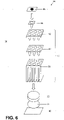
- FIG. 6 shows a perspective view of an instrument 84 according to a first embodiment of the present invention.
- the instrument 84 is configured to perform a temperature-dependent reaction as will be explained in further detail below.
- the instrument 84 comprises an assembly 10 according to any one of the first to fifth embodiments described before. Merely for explaining the basic principle and construction of the instrument 84, the instrument 84 will be described so as to comprise the assembly 10 according to the first embodiment.
- the instrument 84 further comprises at least one laboratory device 86.
- the laboratory device 86 comprises a light source 88 and a detector 90.
- the light source 88 is located above the sample block 12 and faces the upper surface 20 of the sample block 12.
- the light source 88 is configured to emit excitation light towards the sample block 12.
- the detector 90 is located below the heat sink 30 and faces the lower surface 40 of the heat sink 30.
- the detector 90 may be a charge-coupled device sensor, a complementary metal-oxide-semiconductor sensor or the like.
- a lens 92 and an optical filter 94 such as an emission band pass filter may be located between the heat sink 30 and the detector 90.
- the assembly 10 and the instrument 84, respectively, are used to perform a temperature-dependent reaction.
- a sample comprised in a sample vessel 96 is disposed in a recess 14 of the sample block 12.
- the sample is exposed to one or more specified temperatures by operating the electrodeposited thermo electric element 48. More particularly, the electrodeposited thermo electric element 48 is operated so as to cool and/or heat the sample in the sample vessel 96.
- the presence or absence of an analyte in the sample may be determined.
- the sample is provided with a detectable marker which is specific for the analyte.
- the marker is a fluorophore or elechtrochemiluminescent compound.
- the marker is a fluorophore.
- the sample is exposed to excitation light emitted from the light source 88 during the temperature-dependent reaction.
- the light passes the through holes 26, 44, 62 of the recess 14, the electrodeposited thermo electric element 48 and the heat sink 30.
- the light also comes into contact with the marker.
- the light emitted from the marker passes the lens 92 and the optical filter 94 and is subsequently detected by the detector 90. The thus detected light emitted from the marker is indicative of the presence or absence of the analyte.
- Figure 7 shows a perspective view of an instrument 84 according to a second embodiment of the present invention.
- the light source 88 is located below the heat sink 30 and faces the lower surface 40 of the heat sink 30.
- the detector 90 is located above the sample block 12 and faces the upper surface 20 of the sample block 12.
- the lens 92 and the optical filter 94 are located between the sample block 12 and the detector 90. During operation, the light source 88 emits light towards the heat sink 30.
- the light passes the through holes 26, 44, 62 of the recess 14, the electrodeposited thermo electric element 48 and the heat sink 30. Thus, the light also comes into contact with the marker within the sample.
- the light emitted from the marker passes the lens 92 and the optical filter 94 and is subsequently detected by the detector 90. The thus detected light emitted from the marker is indicative of the presence or absence of the analyte.
- FIG 8 shows a perspective view of an instrument 84 according to a third embodiment of the present invention.
- the through holes 26 of the recesses 14 and the through holes 62 of the electrodeposited thermo electric element 48 are omitted.
- a beam splitter 98 is located between the light source 88 and the sample block 12.
- the lens 92, the optical filter 94 and the detector 90 are also located above the sample block 12 but adjacent to or laterally shifted from the light source 88.
- the sample is exposed to excitation light emitted from the light source 88 during the temperature-dependent reaction.
- the light passes the beam splitter 98 and comes into contact the marker within the sample.
- the light is emitted from the marker in an upward direction, i.e. back towards the light source 88.
- the light emitted from the marker hits the beam splitter 98 and is reflected towards the lens 92 and the optical filter 94 and is subsequently detected by the detector 90.
- the thus detected light emitted from the marker is indicative of the presence or absence of the analyte.
Claims (14)
- Anordnung (10), aufweisend einen Probenblock (12), eine Wärmsenke (30) und mindestens ein elektrolytisch abgeschiedenes thermoelektrisches Element (48), wobei der Probenblock (12) mindestens eine Vertiefung (14) aufweist, die zur Aufnahme eines Probengefäßes (96) ausgelegt ist, wobei die Vertiefung (14) in ihrem unteren Ende (28) ein Durchgangsloch (26) aufweist, wobei das elektrolytisch abgeschiedene thermoelektrische Element (48) mindestens ein Durchgangsloch (62) aufweist, wobei die Wärmesenke (30) mindestens ein Durchgangsloch (44), aufweist, wobei das Durchgangsloch (26) der Vertiefung (14), das Durchgangsloch (62) des elektrolytisch abgeschiedenen thermoelektrischen Elements (48) und das Durchgangsloch (44) der Wärmesenke (30) auf einer gemeinsamen Achse (64) ausgerichtet sind.
- Anordnung (10) nach Anspruch 1, wobei das elektrolytisch abgeschiedene thermoelektrische Element (48) zwischen dem Probenblock (12) und der Wärmesenke (30) angeordnet ist.
- Anordnung (10) nach Anspruch 1 oder 2, wobei das elektrolytisch abgeschiedene thermoelektrische Element (48) den Probenblock (12) und/oder die Wärmesenke (30) berührt.
- Anordnung (10) nach einem der Ansprüche 1 bis 3, wobei der Probenblock (12) am elektrolytisch abgeschiedenen thermoelektrischen Element (48) und der Wärmesenke (30) befestigt ist.
- Anordnung (10) nach einem der Ansprüche 1 bis 4, wobei der Probenblock (12) mittels einer Formschlussverbindung und/oder einer Kraftschlussverbindung und/oder einer Haftklebeverbindung am elektrolytisch abgeschiedenen thermoelektrischen Element (48) und der Wärmesenke (30) befestigt ist.
- Anordnung (10) nach einem der Ansprüche 1 bis 5, wobei der Probenblock (12) mindestens ein Befestigungsloch (66) aufweist, wobei das elektrolytisch abgeschiedene thermoelektrische Element (48) mindestens ein Befestigungsloch (68) aufweist, und die Wärmesenke (30) mindestens ein Befestigungsloch (70) aufweist, wobei mindestens ein Gewindebolzen (72) in das Befestigungsloch (66) des Probenblocks (12), das Befestigungsloch (68) des elektrolytisch abgeschiedenen thermoelektrischen Elements (48) und das Befestigungsloch (70) der Wärmesenke (30) eingreift.
- Anordnung (10) nach einem der Ansprüche 1 bis 6, wobei der Probenblock (12) die eine oder die mehreren Vertiefungen (14) aufweist, die jeweils zur Aufnahme eines Probengefäßes (96) ausgelegt sind, wobei die Form des mindestens einen elektrolytisch abgeschiedenen thermoelektrischen Elements (48) an die Form des einen oder der mehreren Vertiefungen (14) angepasst ist.
- Anordnung (10) nach einem der Ansprüche 1 bis 7, wobei die Vertiefung (14) sich in Richtung des elektrolytisch abgeschiedenen thermoelektrischen Elements (48) verjüngt.
- Anordnung (10) nach einem der Ansprüche 1 bis 8, wobei die Vertiefung (14) kegelförmig ist.
- Anordnung (10) nach einem der Ansprüche 1 bis 9, wobei das elektrolytisch abgeschiedene thermoelektrische Element (48) thermoelektrische Zonen (82) aufweist, wobei die Zonen (82) individuell betrieben werden können.
- Anordnung (10) nach Anspruch 10, wobei die thermoelektrischen Zonen (82) identische oder verschiedene Kühlleistungs- oder Wärmeleistungscharakteristiken aufweisen.
- Anordnung (10) nach Anspruch 10 oder 11, wobei jede der thermoelektrischen Zonen (82) Teilabschnitte aufweist, wobei die Teilabschnitte identische oder verschiedene Kühlleistungs- oder Wärmeleistungscharakteristiken aufweisen.
- Instrument (84) zum Durchführen einer temperaturabhängigen Reaktion, aufweisend eine Anordnung (10) nach einem der Ansprüche 1 bis 12 und mindestens eine Laborvorrichtung (86).
- Verfahren zur Durchführung einer temperaturabhängigen Reaktion in einer Anordnung (10) nach einem der Ansprüche 1 bis 12 oder einem Instrument (84) nach Anspruch 13, aufweisend ein Aussetzen einer Probe, die in einem Probengefäß (96) umfasst ist, das in einer Vertiefung (14) eines Probenblocks (12) angeordnet ist, einer oder mehreren spezifizierten Temperaturen durch Betreiben des elektrolytisch abgeschiedenen thermoelektrischen Elements (48).
Priority Applications (1)
| Application Number | Priority Date | Filing Date | Title |
|---|---|---|---|
| EP20188220.6A EP3747546B1 (de) | 2016-09-01 | 2016-09-01 | Anordnung, instrument zur durchführung einer temperaturabhängigen reaktion und verfahren zur durchführung einer temperaturabhängigen reaktion in einer anordnung |
Applications Claiming Priority (3)
| Application Number | Priority Date | Filing Date | Title |
|---|---|---|---|
| EP19175301.1A EP3552707B1 (de) | 2016-09-01 | 2016-09-01 | Anordnung, instrument zur durchführung einer temperaturabhängigen reaktion und verfahren zur durchführung einer temperaturabhängigen reaktion in einer anordnung |
| EP20188220.6A EP3747546B1 (de) | 2016-09-01 | 2016-09-01 | Anordnung, instrument zur durchführung einer temperaturabhängigen reaktion und verfahren zur durchführung einer temperaturabhängigen reaktion in einer anordnung |
| EP16186823.7A EP3290119B1 (de) | 2016-09-01 | 2016-09-01 | Anordnung, instrument zur durchführung einer temperaturabhängigen reaktion und verfahren zur durchführung einer temperaturabhängigen reaktion in einer anordnung |
Related Parent Applications (3)
| Application Number | Title | Priority Date | Filing Date |
|---|---|---|---|
| EP19175301.1A Division-Into EP3552707B1 (de) | 2016-09-01 | 2016-09-01 | Anordnung, instrument zur durchführung einer temperaturabhängigen reaktion und verfahren zur durchführung einer temperaturabhängigen reaktion in einer anordnung |
| EP19175301.1A Division EP3552707B1 (de) | 2016-09-01 | 2016-09-01 | Anordnung, instrument zur durchführung einer temperaturabhängigen reaktion und verfahren zur durchführung einer temperaturabhängigen reaktion in einer anordnung |
| EP16186823.7A Division EP3290119B1 (de) | 2016-09-01 | 2016-09-01 | Anordnung, instrument zur durchführung einer temperaturabhängigen reaktion und verfahren zur durchführung einer temperaturabhängigen reaktion in einer anordnung |
Publications (2)
| Publication Number | Publication Date |
|---|---|
| EP3747546A1 EP3747546A1 (de) | 2020-12-09 |
| EP3747546B1 true EP3747546B1 (de) | 2022-04-13 |
Family
ID=57003319
Family Applications (3)
| Application Number | Title | Priority Date | Filing Date |
|---|---|---|---|
| EP16186823.7A Active EP3290119B1 (de) | 2016-09-01 | 2016-09-01 | Anordnung, instrument zur durchführung einer temperaturabhängigen reaktion und verfahren zur durchführung einer temperaturabhängigen reaktion in einer anordnung |
| EP19175301.1A Active EP3552707B1 (de) | 2016-09-01 | 2016-09-01 | Anordnung, instrument zur durchführung einer temperaturabhängigen reaktion und verfahren zur durchführung einer temperaturabhängigen reaktion in einer anordnung |
| EP20188220.6A Active EP3747546B1 (de) | 2016-09-01 | 2016-09-01 | Anordnung, instrument zur durchführung einer temperaturabhängigen reaktion und verfahren zur durchführung einer temperaturabhängigen reaktion in einer anordnung |
Family Applications Before (2)
| Application Number | Title | Priority Date | Filing Date |
|---|---|---|---|
| EP16186823.7A Active EP3290119B1 (de) | 2016-09-01 | 2016-09-01 | Anordnung, instrument zur durchführung einer temperaturabhängigen reaktion und verfahren zur durchführung einer temperaturabhängigen reaktion in einer anordnung |
| EP19175301.1A Active EP3552707B1 (de) | 2016-09-01 | 2016-09-01 | Anordnung, instrument zur durchführung einer temperaturabhängigen reaktion und verfahren zur durchführung einer temperaturabhängigen reaktion in einer anordnung |
Country Status (4)
| Country | Link |
|---|---|
| US (1) | US10183296B2 (de) |
| EP (3) | EP3290119B1 (de) |
| JP (1) | JP6941006B2 (de) |
| CN (2) | CN107796758B (de) |
Families Citing this family (4)
| Publication number | Priority date | Publication date | Assignee | Title |
|---|---|---|---|---|
| EP3823759B1 (de) * | 2018-07-16 | 2022-03-23 | Brand Gmbh + Co Kg | Temperiervorrichtung für laborgefässe |
| EP3599023B1 (de) | 2018-07-24 | 2021-03-10 | F. Hoffmann-La Roche AG | Verfahren zur überwachung und steuerung der temperatur eines probenhalters eines laborwerkzeugs |
| EP3663002A1 (de) | 2018-12-07 | 2020-06-10 | F. Hoffmann-La Roche AG | Vorrichtung zur thermischen behandlung von testproben |
| WO2023102208A1 (en) * | 2021-12-03 | 2023-06-08 | Adaptive Phage Therapeutics, Inc. | Heating arrangement |
Family Cites Families (18)
| Publication number | Priority date | Publication date | Assignee | Title |
|---|---|---|---|---|
| US6337435B1 (en) * | 1999-07-30 | 2002-01-08 | Bio-Rad Laboratories, Inc. | Temperature control for multi-vessel reaction apparatus |
| US6657169B2 (en) * | 1999-07-30 | 2003-12-02 | Stratagene | Apparatus for thermally cycling samples of biological material with substantial temperature uniformity |
| EP1416041A4 (de) * | 2001-07-06 | 2004-08-04 | Prec System Science Co Ltd | Reaktionsbehälter und -vorrichtung |
| US8676383B2 (en) * | 2002-12-23 | 2014-03-18 | Applied Biosystems, Llc | Device for carrying out chemical or biological reactions |
| WO2004105947A2 (en) * | 2003-05-23 | 2004-12-09 | Bio-Rad Laboratories, Inc. | Localized temperature control for spatial arrays of reaction media |
| WO2005041314A2 (en) * | 2003-10-29 | 2005-05-06 | Elasthermo Ltd. | Thermoelectric device and system |
| JPWO2006019059A1 (ja) | 2004-08-17 | 2008-05-08 | 古河電気工業株式会社 | 熱電冷却装置 |
| US7051536B1 (en) * | 2004-11-12 | 2006-05-30 | Bio-Rad Laboratories, Inc. | Thermal cycler with protection from atmospheric moisture |
| WO2007002588A2 (en) * | 2005-06-23 | 2007-01-04 | Applera Corporation | Thermal-cycling pipette tip |
| EP2148187A1 (de) | 2008-07-25 | 2010-01-27 | Roche Diagnostics GmbH | Anregungs- und Abbildungsoptik für die Fluoreszenzdetektion |
| CN102164674B (zh) * | 2008-09-23 | 2014-07-16 | 皇家飞利浦电子股份有限公司 | 热循环设备 |
| TWI368651B (en) * | 2008-10-24 | 2012-07-21 | Quanta Comp Inc | Temperature variation apparatus |
| US20110312102A1 (en) * | 2010-06-16 | 2011-12-22 | Samsung Techwin Co., Ltd. | Light transmissive temperature control apparatus and bio-diagnosis apparatus including the same |
| US9446410B2 (en) * | 2010-12-03 | 2016-09-20 | Biofire Defense, Llc | Thermal cycler apparatus with elastomeric adhesive |
| WO2012136243A1 (en) | 2011-04-04 | 2012-10-11 | Greenteg Gmbh C/O Eth Zürich, Micro- & Nanosystems | Combined hydroelectric-thermoelectric power plant |
| CA2832759A1 (en) * | 2011-05-06 | 2012-11-15 | Bio-Rad Laboratories, Inc. | Thermal cycler with vapor chamber for rapid temperature changes |
| US20130137144A1 (en) * | 2011-06-08 | 2013-05-30 | Bio-Rad Laboratories, Inc. LSG - GXD Division | Thermal block with built-in thermoelectric elements |
| CN104502324B (zh) * | 2014-12-29 | 2017-04-05 | 东北大学 | 熔盐电化学原位Raman光谱测量用显微热台 |
-
2016
- 2016-09-01 EP EP16186823.7A patent/EP3290119B1/de active Active
- 2016-09-01 EP EP19175301.1A patent/EP3552707B1/de active Active
- 2016-09-01 EP EP20188220.6A patent/EP3747546B1/de active Active
-
2017
- 2017-08-18 CN CN201710712020.5A patent/CN107796758B/zh active Active
- 2017-08-18 CN CN202010261017.8A patent/CN111504902A/zh active Pending
- 2017-08-29 JP JP2017164052A patent/JP6941006B2/ja active Active
- 2017-08-31 US US15/693,009 patent/US10183296B2/en active Active
Also Published As
| Publication number | Publication date |
|---|---|
| US20180056297A1 (en) | 2018-03-01 |
| CN107796758B (zh) | 2020-05-08 |
| JP6941006B2 (ja) | 2021-09-29 |
| EP3552707B1 (de) | 2020-10-21 |
| JP2018037657A (ja) | 2018-03-08 |
| CN111504902A (zh) | 2020-08-07 |
| EP3290119B1 (de) | 2019-06-26 |
| EP3552707A1 (de) | 2019-10-16 |
| CN107796758A (zh) | 2018-03-13 |
| EP3290119A1 (de) | 2018-03-07 |
| EP3747546A1 (de) | 2020-12-09 |
| US10183296B2 (en) | 2019-01-22 |
Similar Documents
| Publication | Publication Date | Title |
|---|---|---|
| US10183296B2 (en) | Assembly, instrument for performing a temperature-dependent reaction and method for performing a temperature-dependent reaction in an assembly | |
| US10286398B2 (en) | Apparatus and method for segmented thermal cycler | |
| US9457351B2 (en) | Device for carrying out chemical or biological reactions | |
| US11643681B2 (en) | Apparatus for high throughput chemical reactions | |
| US8926811B2 (en) | Digital microfluidics based apparatus for heat-exchanging chemical processes | |
| JP5650791B2 (ja) | 熱交換を行ない光学的に検出する化学反応アセンブリ | |
| US9580744B2 (en) | Method and apparatus for applying continuous flow and uniform temperature to generate thermal melting curves in a microfluidic device | |
| US7524672B2 (en) | Microfluidic microarray systems and methods thereof | |
| EP3502276B1 (de) | Vorrichtungen für konvektive polymerasekettenreaktion (pcr) | |
| WO2004024330A2 (en) | Thermocycler and sample holder | |
| CN116635534A (zh) | 用于快速多路复用样品处理的系统和方法及其核酸扩增试验的应用 | |
| US11732973B2 (en) | Device for the thermal treatment of test samples | |
| JP2024505617A (ja) | ウェル制限型熱サイクル装置 | |
| WO2023057338A1 (en) | Integrated system for chemical, biochemical or molecular biological reactions in a microplate |
Legal Events
| Date | Code | Title | Description |
|---|---|---|---|
| PUAI | Public reference made under article 153(3) epc to a published international application that has entered the european phase |
Free format text: ORIGINAL CODE: 0009012 |
|
| STAA | Information on the status of an ep patent application or granted ep patent |
Free format text: STATUS: THE APPLICATION HAS BEEN PUBLISHED |
|
| AC | Divisional application: reference to earlier application |
Ref document number: 3290119 Country of ref document: EP Kind code of ref document: P Ref document number: 3552707 Country of ref document: EP Kind code of ref document: P |
|
| AK | Designated contracting states |
Kind code of ref document: A1 Designated state(s): AL AT BE BG CH CY CZ DE DK EE ES FI FR GB GR HR HU IE IS IT LI LT LU LV MC MK MT NL NO PL PT RO RS SE SI SK SM TR |
|
| STAA | Information on the status of an ep patent application or granted ep patent |
Free format text: STATUS: REQUEST FOR EXAMINATION WAS MADE |
|
| 17P | Request for examination filed |
Effective date: 20210409 |
|
| RBV | Designated contracting states (corrected) |
Designated state(s): AL AT BE BG CH CY CZ DE DK EE ES FI FR GB GR HR HU IE IS IT LI LT LU LV MC MK MT NL NO PL PT RO RS SE SI SK SM TR |
|
| GRAP | Despatch of communication of intention to grant a patent |
Free format text: ORIGINAL CODE: EPIDOSNIGR1 |
|
| STAA | Information on the status of an ep patent application or granted ep patent |
Free format text: STATUS: GRANT OF PATENT IS INTENDED |
|
| RIC1 | Information provided on ipc code assigned before grant |
Ipc: B01L 7/00 20060101AFI20210709BHEP Ipc: H01L 27/16 20060101ALI20210709BHEP Ipc: B01L 3/00 20060101ALI20210709BHEP Ipc: H01L 23/38 20060101ALI20210709BHEP Ipc: H05B 3/10 20060101ALI20210709BHEP Ipc: C12P 19/34 20060101ALI20210709BHEP Ipc: H01L 35/32 20060101ALI20210709BHEP Ipc: H05B 1/02 20060101ALI20210709BHEP |
|
| INTG | Intention to grant announced |
Effective date: 20210803 |
|
| GRAJ | Information related to disapproval of communication of intention to grant by the applicant or resumption of examination proceedings by the epo deleted |
Free format text: ORIGINAL CODE: EPIDOSDIGR1 |
|
| STAA | Information on the status of an ep patent application or granted ep patent |
Free format text: STATUS: REQUEST FOR EXAMINATION WAS MADE |
|
| GRAP | Despatch of communication of intention to grant a patent |
Free format text: ORIGINAL CODE: EPIDOSNIGR1 |
|
| STAA | Information on the status of an ep patent application or granted ep patent |
Free format text: STATUS: GRANT OF PATENT IS INTENDED |
|
| INTC | Intention to grant announced (deleted) | ||
| GRAJ | Information related to disapproval of communication of intention to grant by the applicant or resumption of examination proceedings by the epo deleted |
Free format text: ORIGINAL CODE: EPIDOSDIGR1 |
|
| GRAP | Despatch of communication of intention to grant a patent |
Free format text: ORIGINAL CODE: EPIDOSNIGR1 |
|
| INTG | Intention to grant announced |
Effective date: 20211012 |
|
| INTG | Intention to grant announced |
Effective date: 20211026 |
|
| GRAS | Grant fee paid |
Free format text: ORIGINAL CODE: EPIDOSNIGR3 |
|
| GRAA | (expected) grant |
Free format text: ORIGINAL CODE: 0009210 |
|
| STAA | Information on the status of an ep patent application or granted ep patent |
Free format text: STATUS: THE PATENT HAS BEEN GRANTED |
|
| AC | Divisional application: reference to earlier application |
Ref document number: 3290119 Country of ref document: EP Kind code of ref document: P Ref document number: 3552707 Country of ref document: EP Kind code of ref document: P |
|
| AK | Designated contracting states |
Kind code of ref document: B1 Designated state(s): AL AT BE BG CH CY CZ DE DK EE ES FI FR GB GR HR HU IE IS IT LI LT LU LV MC MK MT NL NO PL PT RO RS SE SI SK SM TR |
|
| REG | Reference to a national code |
Ref country code: GB Ref legal event code: FG4D |
|
| REG | Reference to a national code |
Ref country code: CH Ref legal event code: EP |
|
| REG | Reference to a national code |
Ref country code: DE Ref legal event code: R096 Ref document number: 602016071203 Country of ref document: DE |
|
| REG | Reference to a national code |
Ref country code: IE Ref legal event code: FG4D |
|
| REG | Reference to a national code |
Ref country code: AT Ref legal event code: REF Ref document number: 1482974 Country of ref document: AT Kind code of ref document: T Effective date: 20220515 |
|
| REG | Reference to a national code |
Ref country code: LT Ref legal event code: MG9D |
|
| REG | Reference to a national code |
Ref country code: NL Ref legal event code: MP Effective date: 20220413 |
|
| REG | Reference to a national code |
Ref country code: AT Ref legal event code: MK05 Ref document number: 1482974 Country of ref document: AT Kind code of ref document: T Effective date: 20220413 |
|
| PG25 | Lapsed in a contracting state [announced via postgrant information from national office to epo] |
Ref country code: NL Free format text: LAPSE BECAUSE OF FAILURE TO SUBMIT A TRANSLATION OF THE DESCRIPTION OR TO PAY THE FEE WITHIN THE PRESCRIBED TIME-LIMIT Effective date: 20220413 |
|
| PG25 | Lapsed in a contracting state [announced via postgrant information from national office to epo] |
Ref country code: SE Free format text: LAPSE BECAUSE OF FAILURE TO SUBMIT A TRANSLATION OF THE DESCRIPTION OR TO PAY THE FEE WITHIN THE PRESCRIBED TIME-LIMIT Effective date: 20220413 Ref country code: PT Free format text: LAPSE BECAUSE OF FAILURE TO SUBMIT A TRANSLATION OF THE DESCRIPTION OR TO PAY THE FEE WITHIN THE PRESCRIBED TIME-LIMIT Effective date: 20220816 Ref country code: NO Free format text: LAPSE BECAUSE OF FAILURE TO SUBMIT A TRANSLATION OF THE DESCRIPTION OR TO PAY THE FEE WITHIN THE PRESCRIBED TIME-LIMIT Effective date: 20220713 Ref country code: LT Free format text: LAPSE BECAUSE OF FAILURE TO SUBMIT A TRANSLATION OF THE DESCRIPTION OR TO PAY THE FEE WITHIN THE PRESCRIBED TIME-LIMIT Effective date: 20220413 Ref country code: HR Free format text: LAPSE BECAUSE OF FAILURE TO SUBMIT A TRANSLATION OF THE DESCRIPTION OR TO PAY THE FEE WITHIN THE PRESCRIBED TIME-LIMIT Effective date: 20220413 Ref country code: GR Free format text: LAPSE BECAUSE OF FAILURE TO SUBMIT A TRANSLATION OF THE DESCRIPTION OR TO PAY THE FEE WITHIN THE PRESCRIBED TIME-LIMIT Effective date: 20220714 Ref country code: FI Free format text: LAPSE BECAUSE OF FAILURE TO SUBMIT A TRANSLATION OF THE DESCRIPTION OR TO PAY THE FEE WITHIN THE PRESCRIBED TIME-LIMIT Effective date: 20220413 Ref country code: ES Free format text: LAPSE BECAUSE OF FAILURE TO SUBMIT A TRANSLATION OF THE DESCRIPTION OR TO PAY THE FEE WITHIN THE PRESCRIBED TIME-LIMIT Effective date: 20220413 Ref country code: BG Free format text: LAPSE BECAUSE OF FAILURE TO SUBMIT A TRANSLATION OF THE DESCRIPTION OR TO PAY THE FEE WITHIN THE PRESCRIBED TIME-LIMIT Effective date: 20220713 Ref country code: AT Free format text: LAPSE BECAUSE OF FAILURE TO SUBMIT A TRANSLATION OF THE DESCRIPTION OR TO PAY THE FEE WITHIN THE PRESCRIBED TIME-LIMIT Effective date: 20220413 |
|
| PG25 | Lapsed in a contracting state [announced via postgrant information from national office to epo] |
Ref country code: RS Free format text: LAPSE BECAUSE OF FAILURE TO SUBMIT A TRANSLATION OF THE DESCRIPTION OR TO PAY THE FEE WITHIN THE PRESCRIBED TIME-LIMIT Effective date: 20220413 Ref country code: PL Free format text: LAPSE BECAUSE OF FAILURE TO SUBMIT A TRANSLATION OF THE DESCRIPTION OR TO PAY THE FEE WITHIN THE PRESCRIBED TIME-LIMIT Effective date: 20220413 Ref country code: LV Free format text: LAPSE BECAUSE OF FAILURE TO SUBMIT A TRANSLATION OF THE DESCRIPTION OR TO PAY THE FEE WITHIN THE PRESCRIBED TIME-LIMIT Effective date: 20220413 Ref country code: IS Free format text: LAPSE BECAUSE OF FAILURE TO SUBMIT A TRANSLATION OF THE DESCRIPTION OR TO PAY THE FEE WITHIN THE PRESCRIBED TIME-LIMIT Effective date: 20220813 |
|
| REG | Reference to a national code |
Ref country code: DE Ref legal event code: R097 Ref document number: 602016071203 Country of ref document: DE |
|
| PG25 | Lapsed in a contracting state [announced via postgrant information from national office to epo] |
Ref country code: SM Free format text: LAPSE BECAUSE OF FAILURE TO SUBMIT A TRANSLATION OF THE DESCRIPTION OR TO PAY THE FEE WITHIN THE PRESCRIBED TIME-LIMIT Effective date: 20220413 Ref country code: SK Free format text: LAPSE BECAUSE OF FAILURE TO SUBMIT A TRANSLATION OF THE DESCRIPTION OR TO PAY THE FEE WITHIN THE PRESCRIBED TIME-LIMIT Effective date: 20220413 Ref country code: RO Free format text: LAPSE BECAUSE OF FAILURE TO SUBMIT A TRANSLATION OF THE DESCRIPTION OR TO PAY THE FEE WITHIN THE PRESCRIBED TIME-LIMIT Effective date: 20220413 Ref country code: EE Free format text: LAPSE BECAUSE OF FAILURE TO SUBMIT A TRANSLATION OF THE DESCRIPTION OR TO PAY THE FEE WITHIN THE PRESCRIBED TIME-LIMIT Effective date: 20220413 Ref country code: DK Free format text: LAPSE BECAUSE OF FAILURE TO SUBMIT A TRANSLATION OF THE DESCRIPTION OR TO PAY THE FEE WITHIN THE PRESCRIBED TIME-LIMIT Effective date: 20220413 Ref country code: CZ Free format text: LAPSE BECAUSE OF FAILURE TO SUBMIT A TRANSLATION OF THE DESCRIPTION OR TO PAY THE FEE WITHIN THE PRESCRIBED TIME-LIMIT Effective date: 20220413 |
|
| PLBE | No opposition filed within time limit |
Free format text: ORIGINAL CODE: 0009261 |
|
| STAA | Information on the status of an ep patent application or granted ep patent |
Free format text: STATUS: NO OPPOSITION FILED WITHIN TIME LIMIT |
|
| 26N | No opposition filed |
Effective date: 20230116 |
|
| PG25 | Lapsed in a contracting state [announced via postgrant information from national office to epo] |
Ref country code: AL Free format text: LAPSE BECAUSE OF FAILURE TO SUBMIT A TRANSLATION OF THE DESCRIPTION OR TO PAY THE FEE WITHIN THE PRESCRIBED TIME-LIMIT Effective date: 20220413 |
|
| PG25 | Lapsed in a contracting state [announced via postgrant information from national office to epo] |
Ref country code: MC Free format text: LAPSE BECAUSE OF FAILURE TO SUBMIT A TRANSLATION OF THE DESCRIPTION OR TO PAY THE FEE WITHIN THE PRESCRIBED TIME-LIMIT Effective date: 20220413 |
|
| REG | Reference to a national code |
Ref country code: BE Ref legal event code: MM Effective date: 20220930 |
|
| PG25 | Lapsed in a contracting state [announced via postgrant information from national office to epo] |
Ref country code: SI Free format text: LAPSE BECAUSE OF FAILURE TO SUBMIT A TRANSLATION OF THE DESCRIPTION OR TO PAY THE FEE WITHIN THE PRESCRIBED TIME-LIMIT Effective date: 20220413 |
|
| PG25 | Lapsed in a contracting state [announced via postgrant information from national office to epo] |
Ref country code: LU Free format text: LAPSE BECAUSE OF NON-PAYMENT OF DUE FEES Effective date: 20220901 |
|
| PG25 | Lapsed in a contracting state [announced via postgrant information from national office to epo] |
Ref country code: IE Free format text: LAPSE BECAUSE OF NON-PAYMENT OF DUE FEES Effective date: 20220901 |
|
| PG25 | Lapsed in a contracting state [announced via postgrant information from national office to epo] |
Ref country code: BE Free format text: LAPSE BECAUSE OF NON-PAYMENT OF DUE FEES Effective date: 20220930 |
|
| PGFP | Annual fee paid to national office [announced via postgrant information from national office to epo] |
Ref country code: GB Payment date: 20230823 Year of fee payment: 8 |
|
| PGFP | Annual fee paid to national office [announced via postgrant information from national office to epo] |
Ref country code: FR Payment date: 20230822 Year of fee payment: 8 Ref country code: DE Payment date: 20230822 Year of fee payment: 8 |
|
| PG25 | Lapsed in a contracting state [announced via postgrant information from national office to epo] |
Ref country code: IT Free format text: LAPSE BECAUSE OF FAILURE TO SUBMIT A TRANSLATION OF THE DESCRIPTION OR TO PAY THE FEE WITHIN THE PRESCRIBED TIME-LIMIT Effective date: 20220413 |
|
| PGFP | Annual fee paid to national office [announced via postgrant information from national office to epo] |
Ref country code: CH Payment date: 20231001 Year of fee payment: 8 |