US9388827B2 - Blower fan - Google Patents
Blower fan Download PDFInfo
- Publication number
- US9388827B2 US9388827B2 US13/942,836 US201313942836A US9388827B2 US 9388827 B2 US9388827 B2 US 9388827B2 US 201313942836 A US201313942836 A US 201313942836A US 9388827 B2 US9388827 B2 US 9388827B2
- Authority
- US
- United States
- Prior art keywords
- air inlet
- blower fan
- region
- central axis
- regions
- Prior art date
- Legal status (The legal status is an assumption and is not a legal conclusion. Google has not performed a legal analysis and makes no representation as to the accuracy of the status listed.)
- Active, expires
Links
- 239000010687 lubricating oil Substances 0.000 claims description 31
- 239000012530 fluid Substances 0.000 claims description 15
- 230000009467 reduction Effects 0.000 description 14
- 238000000034 method Methods 0.000 description 5
- 230000003247 decreasing effect Effects 0.000 description 3
- 239000011347 resin Substances 0.000 description 3
- 229920005989 resin Polymers 0.000 description 3
- 238000003491 array Methods 0.000 description 2
- 229910052751 metal Inorganic materials 0.000 description 2
- 239000002184 metal Substances 0.000 description 2
- 229910000838 Al alloy Inorganic materials 0.000 description 1
- 230000009471 action Effects 0.000 description 1
- 238000004891 communication Methods 0.000 description 1
- 238000001816 cooling Methods 0.000 description 1
- 238000005520 cutting process Methods 0.000 description 1
- 239000000428 dust Substances 0.000 description 1
- 238000001704 evaporation Methods 0.000 description 1
- 230000008020 evaporation Effects 0.000 description 1
- 230000009931 harmful effect Effects 0.000 description 1
- 230000002452 interceptive effect Effects 0.000 description 1
- 230000001788 irregular Effects 0.000 description 1
- WABPQHHGFIMREM-UHFFFAOYSA-N lead(0) Chemical compound [Pb] WABPQHHGFIMREM-UHFFFAOYSA-N 0.000 description 1
- 230000001050 lubricating effect Effects 0.000 description 1
- 239000000696 magnetic material Substances 0.000 description 1
- 238000012986 modification Methods 0.000 description 1
- 230000004048 modification Effects 0.000 description 1
- 238000000465 moulding Methods 0.000 description 1
- 239000003921 oil Substances 0.000 description 1
- 230000008569 process Effects 0.000 description 1
- 239000010935 stainless steel Substances 0.000 description 1
- 229910001220 stainless steel Inorganic materials 0.000 description 1
- 230000003068 static effect Effects 0.000 description 1
Images


Classifications
-
- F—MECHANICAL ENGINEERING; LIGHTING; HEATING; WEAPONS; BLASTING
- F04—POSITIVE - DISPLACEMENT MACHINES FOR LIQUIDS; PUMPS FOR LIQUIDS OR ELASTIC FLUIDS
- F04D—NON-POSITIVE-DISPLACEMENT PUMPS
- F04D29/00—Details, component parts, or accessories
- F04D29/40—Casings; Connections of working fluid
- F04D29/42—Casings; Connections of working fluid for radial or helico-centrifugal pumps
- F04D29/4206—Casings; Connections of working fluid for radial or helico-centrifugal pumps especially adapted for elastic fluid pumps
- F04D29/4226—Fan casings
-
- F—MECHANICAL ENGINEERING; LIGHTING; HEATING; WEAPONS; BLASTING
- F04—POSITIVE - DISPLACEMENT MACHINES FOR LIQUIDS; PUMPS FOR LIQUIDS OR ELASTIC FLUIDS
- F04D—NON-POSITIVE-DISPLACEMENT PUMPS
- F04D17/00—Radial-flow pumps, e.g. centrifugal pumps; Helico-centrifugal pumps
- F04D17/08—Centrifugal pumps
- F04D17/16—Centrifugal pumps for displacing without appreciable compression
-
- F—MECHANICAL ENGINEERING; LIGHTING; HEATING; WEAPONS; BLASTING
- F04—POSITIVE - DISPLACEMENT MACHINES FOR LIQUIDS; PUMPS FOR LIQUIDS OR ELASTIC FLUIDS
- F04D—NON-POSITIVE-DISPLACEMENT PUMPS
- F04D25/00—Pumping installations or systems
- F04D25/02—Units comprising pumps and their driving means
- F04D25/06—Units comprising pumps and their driving means the pump being electrically driven
- F04D25/0606—Units comprising pumps and their driving means the pump being electrically driven the electric motor being specially adapted for integration in the pump
- F04D25/0613—Units comprising pumps and their driving means the pump being electrically driven the electric motor being specially adapted for integration in the pump the electric motor being of the inside-out type, i.e. the rotor is arranged radially outside a central stator
- F04D25/062—Details of the bearings
-
- F—MECHANICAL ENGINEERING; LIGHTING; HEATING; WEAPONS; BLASTING
- F04—POSITIVE - DISPLACEMENT MACHINES FOR LIQUIDS; PUMPS FOR LIQUIDS OR ELASTIC FLUIDS
- F04D—NON-POSITIVE-DISPLACEMENT PUMPS
- F04D29/00—Details, component parts, or accessories
- F04D29/40—Casings; Connections of working fluid
- F04D29/42—Casings; Connections of working fluid for radial or helico-centrifugal pumps
- F04D29/4206—Casings; Connections of working fluid for radial or helico-centrifugal pumps especially adapted for elastic fluid pumps
- F04D29/4213—Casings; Connections of working fluid for radial or helico-centrifugal pumps especially adapted for elastic fluid pumps suction ports
-
- F—MECHANICAL ENGINEERING; LIGHTING; HEATING; WEAPONS; BLASTING
- F04—POSITIVE - DISPLACEMENT MACHINES FOR LIQUIDS; PUMPS FOR LIQUIDS OR ELASTIC FLUIDS
- F04D—NON-POSITIVE-DISPLACEMENT PUMPS
- F04D29/00—Details, component parts, or accessories
- F04D29/40—Casings; Connections of working fluid
- F04D29/42—Casings; Connections of working fluid for radial or helico-centrifugal pumps
- F04D29/4206—Casings; Connections of working fluid for radial or helico-centrifugal pumps especially adapted for elastic fluid pumps
- F04D29/422—Discharge tongues
-
- F—MECHANICAL ENGINEERING; LIGHTING; HEATING; WEAPONS; BLASTING
- F04—POSITIVE - DISPLACEMENT MACHINES FOR LIQUIDS; PUMPS FOR LIQUIDS OR ELASTIC FLUIDS
- F04D—NON-POSITIVE-DISPLACEMENT PUMPS
- F04D29/00—Details, component parts, or accessories
- F04D29/40—Casings; Connections of working fluid
- F04D29/42—Casings; Connections of working fluid for radial or helico-centrifugal pumps
- F04D29/4206—Casings; Connections of working fluid for radial or helico-centrifugal pumps especially adapted for elastic fluid pumps
- F04D29/4226—Fan casings
- F04D29/424—Double entry casings
-
- F—MECHANICAL ENGINEERING; LIGHTING; HEATING; WEAPONS; BLASTING
- F04—POSITIVE - DISPLACEMENT MACHINES FOR LIQUIDS; PUMPS FOR LIQUIDS OR ELASTIC FLUIDS
- F04D—NON-POSITIVE-DISPLACEMENT PUMPS
- F04D25/00—Pumping installations or systems
- F04D25/02—Units comprising pumps and their driving means
- F04D25/06—Units comprising pumps and their driving means the pump being electrically driven
- F04D25/0606—Units comprising pumps and their driving means the pump being electrically driven the electric motor being specially adapted for integration in the pump
- F04D25/0613—Units comprising pumps and their driving means the pump being electrically driven the electric motor being specially adapted for integration in the pump the electric motor being of the inside-out type, i.e. the rotor is arranged radially outside a central stator
-
- F—MECHANICAL ENGINEERING; LIGHTING; HEATING; WEAPONS; BLASTING
- F04—POSITIVE - DISPLACEMENT MACHINES FOR LIQUIDS; PUMPS FOR LIQUIDS OR ELASTIC FLUIDS
- F04D—NON-POSITIVE-DISPLACEMENT PUMPS
- F04D29/00—Details, component parts, or accessories
- F04D29/05—Shafts or bearings, or assemblies thereof, specially adapted for elastic fluid pumps
- F04D29/051—Axial thrust balancing
- F04D29/0513—Axial thrust balancing hydrostatic; hydrodynamic thrust bearings
-
- F—MECHANICAL ENGINEERING; LIGHTING; HEATING; WEAPONS; BLASTING
- F04—POSITIVE - DISPLACEMENT MACHINES FOR LIQUIDS; PUMPS FOR LIQUIDS OR ELASTIC FLUIDS
- F04D—NON-POSITIVE-DISPLACEMENT PUMPS
- F04D29/00—Details, component parts, or accessories
- F04D29/05—Shafts or bearings, or assemblies thereof, specially adapted for elastic fluid pumps
- F04D29/056—Bearings
- F04D29/057—Bearings hydrostatic; hydrodynamic
Definitions
- the present invention relates to a slim blower fan installed in a notebook PC or the like.
- Fans have been arranged inside cases of a variety of electronic devices and household electrical appliances.
- electronic components such as CPUs
- installed inside cases thereof generate heat, and measures need to be taken against the heat inside the cases.
- measures against the heat is to install centrifugal fans inside the cases to discharge the heat out of the cases.
- One known method of increasing the air volume is to provide air inlets in both an upper surface and a lower surface of a fan casing of a centrifugal fan as disclosed in JP-A 2008-157216. In addition, it is necessary to increase the rotation speed of the centrifugal fan to increase the air volume.
- a cooling fan including a dynamic pressure bearing as disclosed in JP-A 2006-57838 is considered as a method of reducing vibrations which accompany rotation of the fan. Transfer of vibrations which occur in a rotating body to a case can be reduced by adoption of a dynamic pressure bearing which uses a liquid lubricant, such as an oil, in a bearing portion, since a circumference of a shaft is held by the lubricating fluid.
- the dynamic pressure bearing as disclosed in JP-A 2006-57838 includes a thrust dynamic pressure bearing extending radially, and this thrust dynamic pressure bearing prevents an excessive lift of the rotating body.
- the diameter of a rotor cup is necessarily large because the thrust dynamic pressure bearing extending radially is included in the dynamic pressure bearing, and the radial dimension of each blade is decreased relative to the diameter of the rotor cup. That is, a centrifugal fan which adopts a fluid dynamic bearing in order to reduce vibrations which accompany high-speed rotation tends to have a small air volume. That is, in the case of the centrifugal fan which adopts the fluid dynamic bearing, an air volume characteristic and a vibration characteristic stand in a trade-off relationship.
- a blower fan includes a stationary portion, a bearing portion, and a rotating portion supported by the bearing portion to be rotatable with respect to the stationary portion.
- the rotating portion includes a shaft arranged to extend along a central axis extending in a vertical direction, and inserted in the bearing portion; a blade support portion arranged radially outward of the shaft, and arranged to rotate about the central axis together with the shaft; and a plurality of blades arranged in an annular shape radially outside the blade support portion, and arranged to rotate about the central axis together with the shaft.
- the stationary portion includes a lower plate arranged to cover the blades from below, and arranged to hold the bearing portion directly or indirectly; an upper plate arranged to cover the blades from above; and a side wall portion arranged to cover the blades from radially outside, and having a lower end portion fixed to the lower plate. Edges of the side wall portion at both ends of an opening of the side wall portion, an edge of the upper plate which extends between the edges of the side wall portion, and an edge of the lower plate which extends between the edges of the side wall portion are arranged to together define an air outlet.
- An inside surface of the bearing portion, an outside surface of the shaft, and a lubricating oil arranged in a radial gap defined between the inside surface of the bearing portion and the outside surface of the shaft are arranged to together define a radial dynamic pressure bearing portion arranged to generate a fluid dynamic pressure in the lubricating oil.
- Axially opposed surfaces of the bearing portion and the rotating portion and the lubricating oil arranged in a thrust gap defined between these surfaces are arranged to together define a thrust dynamic pressure bearing portion arranged to generate a fluid dynamic pressure in the lubricating oil in the thrust gap.
- the lower plate includes a lower air inlet arranged to pass through the lower plate in the vertical direction, and arranged radially outward of the bearing portion.
- the upper plate includes an upper air inlet arranged to pass through the upper plate in the vertical direction.
- An inside surface of the side wall portion includes a tongue portion where a radial distance between the inside surface of the side wall portion and any of the blades is shortest.
- a plane is divided into four regions by a first straight line which is parallel to the air outlet and crosses the central axis and a second straight line which is perpendicular to the air outlet and crosses the central axis, and one of the four regions in which the tongue portion is arranged is a first region, followed by a second region, a third region, and a fourth region in this order in a rotation direction of the blades.
- the air outlet is arranged to extend over both the first and fourth regions. At least a portion of the lower air inlet is arranged in the fourth region. A radial distance between the central axis and a radially outer edge of the lower air inlet is arranged to be longest in the fourth region.
- a blower fan according to a preferred embodiment of the present invention is able to achieve a reduction in vibrations and an increase in air volume.
- FIG. 1 is a cross-sectional view of a blower fan according to a preferred embodiment of the present invention.
- FIG. 2 is a cross-sectional view of a bearing portion and its vicinity according to the preferred embodiment of the present invention.
- FIG. 3 is a cross-sectional view of the bearing portion.
- FIG. 4 is a plan view of the bearing portion.
- FIG. 5 is a plan view of the blower fan.
- FIG. 6 is a bottom view of the blower fan.
- FIG. 7 is a plan view of the blower fan.
- FIG. 8 is a plan view of the blower fan.
- FIG. 9 is a bottom view of the blower fan.
- FIG. 10 is a plan view of a blower fan according to another preferred embodiment of the present invention.
- FIG. 11 is a bottom view of the blower fan according to this other preferred embodiment.
- FIG. 12 is a plan view of a blower fan according to yet another preferred embodiment of the present invention.
- FIG. 13 is a plan view of a blower fan according to yet another preferred embodiment of the present invention.
- FIG. 14 is a cross-sectional view of a bearing portion and its vicinity of a blower fan according to yet another preferred embodiment of the present invention.
- an upper side and a lower side in a direction parallel to a central axis J1 of a blower fan illustrated in FIG. 1 are referred to simply as an upper side and a lower side, respectively.
- a vertical direction assumed herein may not necessarily correspond with a vertical direction of the blower fan when the blower fan is actually installed in a device.
- FIG. 1 is a cross-sectional view of a blower fan 1 according to a preferred embodiment of the present invention.
- the blower fan 1 is a centrifugal fan.
- the blower fan 1 is, for example, installed in a notebook personal computer (hereinafter referred to as a “notebook PC”), and used to cool devices inside a case of the notebook PC.
- notebook PC notebook personal computer
- the blower fan 1 includes a stationary portion 2 , a bearing portion 3 , and a rotating portion 4 .
- the rotating portion 4 is centered on the central axis J1 extending in the vertical direction.
- the rotating portion 4 is supported by the bearing portion 3 to be rotatable with respect to the stationary portion 2 .
- the stationary portion 2 includes a lower plate 211 , a side wall portion 212 , an upper plate 213 , and an air outlet 22 .
- the lower plate 211 is arranged to cover a plurality of blades 46 of the rotating portion 4 from below. The blades 46 will be described in detail below.
- the lower plate 211 is arranged to hold the bearing portion 3 .
- the bearing portion 3 is fixed to the lower plate 211 through a bushing 25 of the stationary portion 2 .
- the bushing 25 will be described below. That is, the lower plate 211 is arranged to indirectly hold the bearing portion 3 . Note, however, that the lower plate 211 may be arranged to directly hold the bearing portion 3 .
- the lower plate 211 includes a lower air inlet 211 a arranged to pass through the lower plate 211 in the vertical direction, and arranged in a substantially annular shape.
- a radially inner edge 211 c of the lower air inlet 211 a is an edge of a substantially annular surface facing radially outward.
- a radially outer edge 211 d of the lower air inlet 211 a is an edge of a substantially annular surface facing radially inward.
- the lower air inlet 211 a is arranged radially outward of the bearing portion 3 .
- the side wall portion 212 is arranged to cover the rotating portion 4 from radially outside. A lower end portion of the side wall portion 212 is fixed to the lower plate 211 .
- the upper plate 213 is arranged to cover the blades 46 of the rotating portion 4 from above. In the present preferred embodiment, the upper plate 213 is arranged to cover the entire rotating portion 4 from above. Note, however, that a portion of the rotating portion 4 may be arranged to project above the upper plate 213 through an upper air inlet 213 a , which will be described below.
- the upper plate 213 includes the upper air inlet 213 a , which is substantially circular and is arranged to pass through the upper plate 213 in the vertical direction.
- An edge 213 c of the upper air inlet 213 a is arranged radially inward of an outside surface of each of the blades 46 , that is, a radially outer end portion of each of the blades 46 .
- the upper plate 213 is fixed to an upper end portion of the side wall portion 212 .
- the lower plate 211 , the side wall portion 212 , and the upper plate 213 are arranged to together define a housing 21 .
- Both the edge 213 c of the upper air inlet 213 a and the radially outer edge 211 d of the lower air inlet 211 a are arranged radially inward of the radially outer end portion of each of the blades 46 .
- blower fan 1 In the case where an edge of an air inlet is arranged radially outward of a plurality of blades, there is generally a possibility that a backflow of an air will occur, which may lead to reductions in both air volume and static pressure.
- the blower fan 1 according to the present preferred embodiment is able to prevent a backflow of an air.
- Each of the lower and upper plates 211 and 213 is made of a metal, such as an aluminum alloy or stainless steel, and is in the shape of a thin plate.
- the side wall portion 212 is molded of a resin.
- the lower end portion of the side wall portion 212 and a periphery portion of the lower plate 211 are fastened to each other by an insert molding process.
- the upper plate 213 is fixed to a top portion of the side wall portion 212 through screws. Note, however, that there are various fixing methods which are adoptable, and that use of the aforementioned fixing methods is not essential to the present invention.
- the air outlet 22 is defined by edges 212 a (see FIG. 5 ) of the side wall portion 212 at both ends of an opening of the side wall portion 212 , an edge 213 b of the upper plate 213 which extends between the edges 212 a of the side wall portion 212 , and an edge 211 b of the lower plate 211 which extends between the edges 212 a of the side wall portion 212 .
- the stationary portion 2 further includes a stator 23 and a circuit board 24 .
- the stator 23 is annular and centered on the central axis J1, and is arranged radially outward of the bearing portion 3 .
- the stator 23 includes an annular core back 231 , a plurality of teeth 232 , and coils 233 .
- the teeth 232 are arranged to project radially outward from the core back 231 .
- Each coil 233 is defined by a conducting wire wound around a separate one of the teeth 232 .
- the circuit board 24 is arranged below the coils 233 and above the lower plate 211 . In the present preferred embodiment, the circuit board 24 is arranged on an upper surface of the lower plate 211 . Lead wires from the coils 233 are electrically connected to the circuit board 24 .
- the circuit board 24 is a flexible printed circuit (FPC) board.
- the circuit board 24 includes a connection portion 241 arranged to extend out of the blower fan 1 .
- the connection portion 241 is a portion used to connect the blower fan 1 with an external device.
- the connection portion 241 according to the present preferred embodiment is an extension portion of the flexible printed circuit board.
- the circuit board 24 according to the present preferred embodiment is the flexible printed circuit board, the circuit board 24 may be a rigid board in other preferred embodiments of the present invention. In the case where the circuit board 24 is the rigid board, the connection portion 241 may be, for example, a lead wire.
- the rotating portion 4 includes a shaft 41 , a rotor hub 42 , a yoke 43 , a rotor magnet 44 , a blade support portion 45 , and the blades 46 .
- the shaft 41 is arranged to extend along the central axis J1.
- the rotor hub 42 is arranged to extend radially outward from an upper end portion of the shaft 41 .
- the rotor hub 42 is a portion which is substantially in the shape of a covered cylinder.
- the rotor hub 42 and the shaft 41 are defined integrally with each other according to the present preferred embodiment. Note, however, that the rotor hub 42 and the shaft 41 may be defined by separate members.
- the blade support portion 45 is a resin member which is substantially cylindrical and centered on the central axis J1.
- the blade support portion 45 is arranged radially outward of the shaft 41 , and is arranged to rotate about the central axis J1 together with the shaft 41 .
- the yoke 43 is substantially cylindrical and centered on the central axis J1.
- the yoke 43 is made of a soft magnetic material.
- the yoke 43 is arranged radially inward of the blade support portion 45 .
- the rotor magnet 44 is substantially cylindrical and centered on the central axis J1, and is fixed to an inside surface of the yoke 43 .
- An inside surface of the rotor magnet 44 is arranged radially opposite an outside surface of each of the teeth 232 .
- a current is supplied to the stator 23 to produce a torque centered on the central axis J1 between the rotor magnet 44 and the stator 23 .
- the blades 46 are arranged in an annular shape radially outside the blade support portion 45 .
- the blades 46 are arranged at regular intervals in a circumferential direction. Note, however, that the blades 46 may be arranged at irregular intervals in the circumferential direction.
- the blades 46 are arranged to rotate about the central axis J1 together with the shaft 41 .
- the blade support portion 45 and the blades 46 are defined as a unitary resin member. Rotation of the blades 46 causes an air to be sucked into the housing 21 through each of the upper and lower air inlets 213 a and 211 a and to be discharged through the air outlet 22 .
- FIG. 2 is a cross-sectional view of the bearing portion 3 and its vicinity.
- the bearing portion 3 is a fluid dynamic bearing apparatus arranged to generate a fluid dynamic pressure in a lubricating oil 5 .
- the lubricating oil 5 is arranged in a gap defined between the bearing portion 3 and the rotating portion 4 .
- Provision of the bearing portion 3 i.e., the fluid dynamic bearing apparatus, in the blower fan 1 contributes to reducing vibrations which accompany rotation of the blower fan 1 .
- the bearing portion 3 is able to reduce the vibrations even when a rotation rate of the blower fan 1 is small, but the bearing portion 3 is able to reduce the vibrations more effectively when the rotation rate of the blower fan 1 is large.
- the rotating portion 4 is supported through the bearing portion 3 to be rotatable about the central axis J1 with respect to the stationary portion 2 .
- the bearing portion 3 has a bottom and is substantially cylindrical and centered on the central axis J1.
- the shaft 41 is inserted in the bearing portion 3 .
- the lubricating oil 5 is arranged in a radial gap 51 defined between an inside surface 32 of the bearing portion 3 and an outside surface 41 a of the shaft 41 .
- the inside surface 32 of the bearing portion 3 , the outside surface 41 a of the shaft 41 , and the lubricating oil 5 are arranged to together define a radial dynamic pressure bearing portion 3 a.
- FIG. 3 is a cross-sectional view of the bearing portion 3 .
- An upper portion of the inside surface 32 of the bearing portion 3 includes a first radial dynamic pressure groove array 32 a arranged, for example, in a herringbone pattern.
- a lower portion of the inside surface 32 of the bearing portion 3 includes a second radial dynamic pressure groove array 32 b arranged, for example, in a herringbone pattern. That is, the radial dynamic pressure bearing portion 3 a includes the first and second radial dynamic pressure groove arrays 32 a and 32 b .
- Rotation of the rotating portion 4 causes the radial dynamic pressure bearing portion 3 a to generate a fluid dynamic pressure in the lubricating oil 5 through the first and second radial dynamic pressure groove arrays 32 a and 32 b . While the blower fan 1 is rotating, the shaft 41 is radially supported by the radial dynamic pressure bearing portion 3 a.
- An upper surface 33 of the bearing portion 3 is arranged axially opposite a lower surface 42 a of the rotor hub 42 .
- the lubricating oil 5 is arranged in a thrust gap 52 defined between the upper surface 33 of the bearing portion 3 and the lower surface 42 a of the rotor hub 42 .
- the upper surface 33 of the bearing portion 3 , the lower surface 42 a of the rotor hub 42 , and the lubricating oil 5 are arranged to together define a thrust dynamic pressure bearing portion 3 b .
- FIG. 4 is a plan view of the bearing portion 3 .
- the upper surface 33 of the bearing portion 3 includes a thrust dynamic pressure groove array 33 a arranged, for example, in a spiral pattern.
- the rotation of the rotating portion 4 causes the thrust dynamic pressure bearing portion 3 b to generate a fluid dynamic pressure in the lubricating oil 5 through the thrust dynamic pressure groove array 33 a . While the blower fan 1 is rotating, the rotor hub 42 is axially supported by the thrust dynamic pressure bearing portion 3 b.
- the bearing portion 3 includes a circular lower space 53 arranged to extend radially outward from a lower end of a hole in which the shaft 41 is inserted.
- the lubricating oil 5 is arranged in the lower space 53 .
- the bearing portion 3 further includes a communicating hole 35 arranged to bring the lower space 53 and the thrust gap 52 defined between the upper surface 33 of the bearing portion 3 and the lower surface 42 a of the rotor hub 42 into communication with each other.
- the communicating hole 35 is arranged to pass through the bearing portion 3 in the vertical direction. Provision of the communicating hole 35 enables the lubricating oil 5 to circulate in the gap defined between the bearing portion 3 and the rotating portion 4 while the blower fan 1 is rotating.
- a thrust plate 47 arranged to extend radially outward from a lower end portion of the shaft 41 is accommodated in the lower space 53 .
- the rotor hub 42 includes a hub cylindrical portion 42 b which is cylindrical and is arranged to extend axially downward from the lower surface 42 a of the rotor hub 42 .
- a single seal gap 54 is defined between an inside surface 42 b 1 of the hub cylindrical portion 42 b and an upper portion of an outside surface 36 of the bearing portion 3 .
- the seal gap 54 is arranged to gradually increase in radial width with decreasing height.
- the seal gap 54 is an annular space centered on the central axis J1.
- the lubricating oil 5 is held in the seal gap 54 through capillary action. As a surface of the lubricating oil 5 in the seal gap 54 moves downward, the surface of the lubricating oil 5 increases in surface area, and receives a greater upward pressure caused by an atmospheric pressure. That is, the seal gap 54 makes downward movement of the surface of the lubricating oil 5 less likely to occur.
- the radial gap 51 , the thrust gap 52 , the lower space 53 , and the seal gap 54 are arranged to together define a single continuous bladder structure, and the lubricating oil 5 is arranged continuously in this bladder structure.
- the surface of the lubricating oil 5 in the seal gap 54 is the sole surface of the lubricating oil 5 in the blower fan 1 .
- the stationary portion 2 further includes the bushing 25 , which is substantially annular.
- An inside surface of the bushing 25 is fixed to a lower portion of the outside surface 36 of the bearing portion 3 .
- the bushing 25 is a metallic member defined by a cutting process.
- the inside surface of the bushing 25 is fixed to a lower region of the outside surface of the bearing portion 3 .
- an outside surface of the bushing 25 is fixed to an inside surface of the lower plate 211 . That is, in the present preferred embodiment, the lower plate 211 is arranged to indirectly hold the bearing portion 3 through the bushing 25 .
- the bushing 25 includes a bushing cylindrical portion 25 a which is cylindrical and is arranged to extend axially upward from an upper surface of the bushing 25 .
- An annular labyrinth gap 55 extending in an axial direction is defined between an inside surface of the bushing cylindrical portion 25 a and an outside surface of the hub cylindrical portion 42 b .
- the labyrinth gap 55 is arranged radially outward of the seal gap 54 .
- the labyrinth gap 55 is arranged to have a radial width smaller than that of an opening of the seal gap 54 .
- Provision of the labyrinth gap 55 in the blower fan 1 contributes to reducing the likelihood that an air including an evaporated portion of the lubricating oil 5 will travel from the seal gap 54 to an outside of the bearing portion 3 . This contributes to reducing evaporation of the lubricating oil 5 out of the bearing portion 3 . Moreover, the provision of the labyrinth gap 55 in the blower fan 1 contributes to reducing the likelihood that dust, dirt, or the like will enter into the lubricating oil 5 .
- the hub cylindrical portion 42 b is a portion of the rotor hub 42 .
- the hub cylindrical portion 42 b and the rotor hub 42 may be defined by separate members.
- the hub cylindrical portion 42 b is fixed to the rotor hub 42
- the labyrinth gap 55 is defined between the inside surface of the bushing cylindrical portion 25 a and the outside surface of the hub cylindrical portion 42 b separate from the rotor hub 42 .
- An inside surface of the core back 231 of the stator 23 is fixed to an outside surface of the bushing cylindrical portion 25 a .
- the seal gap 54 , the labyrinth gap 55 , and the core back 231 are arranged to radially overlap with one another.
- FIG. 5 is a plan view of the blower fan 1 .
- the blades 46 are arranged to rotate in a counterclockwise direction in FIG. 5 .
- a rotation direction of the blades 46 and a direction opposite to the rotation direction of the blades 46 will be hereinafter referred to simply as a “rotation direction” and a “counter-rotation direction”, respectively.
- the rotation of the blades 46 causes an air to be sucked into the housing 21 through each of the upper air inlet 213 a (not shown in FIG. 5 ) and the lower air inlet 211 a and to be discharged through the air outlet 22 .
- the side wall portion 212 includes a first side wall portion 212 b , a second side wall portion 212 c , and a third side wall portion 212 d .
- Each of the first, second, and third side wall portions 212 b , 212 c , and 212 d is arranged to extend in parallel with the central axis J1 in the vertical direction.
- the first side wall portion 212 b is arranged on an opposite side of the central axis J1 with respect to the air outlet 22 .
- the first side wall portion 212 b is arranged to extend in a curve along outer circumferences of the blades 46 .
- the first side wall portion 212 b is arranged to extend in a circumferential direction about an axis extending in the vertical direction and displaced from the central axis J1.
- the second side wall portion 212 c is arranged to extend in the rotation direction from the first side wall portion 212 b while becoming more distant from the central axis J1.
- the third side wall portion 212 d is arranged to extend in the counter-rotation direction from the first side wall portion 212 b while approaching the central axis J1.
- An edge of the second side wall portion 212 c at an end portion thereof on a forward side in the rotation direction and an edge of the third side wall portion 212 d at an end portion thereof on a rearward side in the rotation direction are the edges 212 a of the side wall portion 212 at both ends of the opening of the side wall portion 212 . That is, both the edge of the second side wall portion 212 c at the end portion thereof on the forward side in the rotation direction and the edge of the third side wall portion 212 d at the end portion thereof on the rearward side in the rotation direction are portions of an edge defining the air outlet 22 .
- the third side wall portion 212 d includes a tongue portion 212 d 1 arranged to project toward the second side wall portion 212 c .
- the radial distance between an inside surface of the side wall portion 212 and the outside surface of any of the blades 46 is shortest at the tongue portion 212 d 1 . That is, the inside surface of the side wall portion 212 includes the tongue portion 212 d 1 where the radial distance between the inside surface of the side wall portion 212 and any of the blades 46 is shortest.
- Chain lines 71 and 72 passing through the central axis J1 in FIG. 5 are, respectively, a first straight line 71 which is parallel to the air outlet 22 and crosses the central axis J1 in a plan view of the blower fan 1 , and a second straight line 72 which is perpendicular to the air outlet 22 and crosses the central axis J1 in the plan view of the blower fan 1 .
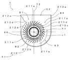
- FIG. 6 is a bottom view of the blower fan 1 .
- a plane is divided into four regions by the first and second straight lines 71 and 72 , and that one of the four regions in which the tongue portion 212 d 1 is arranged is a first region 81 , followed by a second region 82 , a third region 83 , and a fourth region 84 in this order in the rotation direction.
- the air outlet 22 is arranged to extend over both the first and fourth regions 81 and 84 .
- the radial distance between the central axis J1 and the radially outer edge 211 d of the lower air inlet 211 a is longest in the fourth region 84 out of the first to fourth regions 81 , 82 , 83 , and 84 .
- the amount of air sucked in through the upper and lower air inlets 213 a and 211 a during the rotation of the blades 46 increases in the rotation direction with the tongue portion 212 d 1 as a starting point.
- the air is discharged through the air outlet 22 along an inside surface of the second side wall portion 212 c.
- the amount of air sucked in depends on the radial distance between the blades and the side wall portion and the axial distance between the upper surface of the lower plate and the lower surface of the upper plate.
- the amount of air sucked in in the first to third regions is especially small.
- the amount of air discharged through the air outlet in the first region is small.
- the radial distance between the central axis J1 and the radially outer edge 211 d of the lower air inlet 211 a is longest in the fourth region 84 out of the first to fourth regions 81 , 82 , 83 , and 84 .
- the amount of air sucked in in the fourth region 84 is accordingly increased. This overcomes the problem of a limited amount of air discharged through the air outlet 22 in the first region 81 , leading to an increased air volume of the blower fan 1 .
- the blower fan 1 achieves a reduction in vibrations by including the fluid dynamic bearing apparatus, and moreover achieves an increase in the air volume despite inclusion of the fluid dynamic bearing apparatus.
- the lower plate is arranged to hold the bearing portion radially inside the lower air inlet, and therefore, the area of an opening of the lower air inlet is smaller than the area of an opening of the upper air inlet. Accordingly, the amount of air sucked in through the lower air inlet is smaller than the amount of air sucked in through the upper air inlet. Furthermore, as mentioned above, in a slim blower fan in particular, the amount of air sucked in in the first to third regions is especially small. Therefore, a large amount of air is not expected to be sucked in through the lower air inlet in the first to third regions. In other words, a large amount of air is expected to be sucked in through the lower air inlet in the fourth region.
- the radial distance between the central axis J1 and the radially outer edge 211 d of the lower air inlet 211 a is longest in the fourth region 84 out of the first to fourth regions 81 , 82 , 83 , and 84 .
- the amount of air sucked in through the lower air inlet 211 a in the fourth region 84 is accordingly increased.
- a sufficient rigidity of the lower plate 211 is secured because the total area of openings of the lower air inlet 211 a in the first to third regions 81 , 82 , and 83 , where a large amount of air is not expected to be sucked in, is not increased. This leads to a more effective reduction in noise of the blower fan 1 .
- the lower air inlet 211 a is arranged to extend over all of the first to fourth regions 81 , 82 , 83 , and 84 . Note, however, that no portion of the lower air inlet 211 a may be arranged in each of the first to third regions 81 , 82 , and 83 . For example, the lower air inlet 211 a may be arranged only in the fourth region 84 . Alternatively, portions of the lower air inlet 211 a may be arranged in the fourth region 84 and one or two of the first to third regions 81 , 82 , and 83 .
- the substantially annular lower air inlet 211 a may be considered to be a collection of a plurality of air inlet portions 211 a ′ each of which is substantially in the shape of a circular arc and which are arranged in the circumferential direction.
- each air inlet portion 211 a ′ is substantially in the shape of a circular arc. Note, however, that each air inlet portion 211 a ′ may not necessarily be substantially in the shape of a circular arc.
- the air inlet portion 211 a ′ having a portion thereof arranged in the fourth region 84 is arranged to extend over both the third and fourth regions 83 and 84 . That is, an end portion of the air inlet portion 211 a ′ having a portion thereof arranged in the fourth region 84 on the rearward side in the rotation direction is arranged in the third region 83 . Moreover, the air inlet portion 211 a ′ having a portion thereof arranged in the fourth region 84 is arranged to extend over both the first and fourth regions 81 and 84 . That is, an end portion of the air inlet portion 211 a ′ having a portion thereof arranged in the fourth region 84 on the forward side in the rotation direction is arranged in the first region 81 .
- the ribs 211 e are arranged in the first to third regions 81 , 82 , and 83 , and the lower plate 211 includes no rib 211 e in the fourth region 84 .
- the amount of air sucked in through the lower air inlet 211 a in the fourth region 84 is thereby increased. This leads to an increased air volume of the blower fan 1 .
- the number of ribs 211 e is three in the present preferred embodiment, the number of ribs 211 e may not necessarily be three.
- the air inlet portion 211 a ′ having a portion thereof arranged in the fourth region 84 is arranged to have the greatest circumferential dimension of all the air inlet portions 211 a ′ of the lower air inlet 211 a . This leads to a more effective increase in the air volume of the blower fan 1 .
- the air inlet portion 211 a ′ having a portion thereof arranged in the fourth region 84 is arranged to have the greatest radial width of all the air inlet portions 211 a ′ of the lower air inlet 211 a . This arrangement also leads to a more effective increase in the air volume of the blower fan 1 .
- the tongue portion 212 d 1 includes a proximity point 212 d 2 where the tongue portion 212 d 1 is closest to the outer end portion of any of the blades 46 .
- a chain line 73 passing through the central axis J1 is a third straight line 73 which joins the proximity point 212 d 2 and the central axis J1 in the plan view of the blower fan 1 .
- the plane is divided into two regions by the third straight line 73 , and that, of the two regions, a region in which the tongue portion 212 d 1 is arranged is assumed to be a fifth region 85 , and the other region is assumed to be a sixth region 86 . That is, the tongue portion 212 d 1 is arranged in both the first and fifth regions 81 and 85 .
- the upper plate 213 and the circuit board 24 are not shown in FIG. 7 as well.
- the end portion of the air inlet portion 211 a ′ having a portion thereof arranged in the fourth region 84 on the forward side in the rotation direction is arranged in both the first and sixth regions 81 and 86 . That is, the end portion of the air inlet portion 211 a ′ having a portion thereof arranged in the fourth region 84 on the forward side in the rotation direction is arranged in the sixth region 86 .
- This contributes to reducing the likelihood that an air sucked in through the air inlet portion 211 a ′ having a portion thereof arranged in the fourth region 84 will blow into the fifth region 85 beyond the tongue portion 212 d 1 . Accordingly, the air is efficiently discharged through the air outlet 22 .
- the circumferential position of a point on the edge 213 c of the upper air inlet 213 a where the distance between the edge 213 c of the upper air inlet 213 a and the central axis J1 is longest is arranged to axially coincide with the circumferential position of a point on the radially outer edge 211 d of the lower air inlet 211 a in the fourth region 84 where the distance between the radially outer edge 211 d and the central axis J1 is longest.
- the position of a point where the radial distance between the central axis J1 and the edge 213 c of the upper air inlet 213 a is longest coincides with the position of a point where the radial distance between the central axis J1 and the radially outer edge 211 d of the lower air inlet 211 a is longest. Therefore, in the present preferred embodiment, an air is efficiently sucked in through the upper air inlet 213 a as well.
- connection portion 241 is drawn out downwardly through the lower air inlet 211 a from above the lower plate 211 in the third region 83 .
- a large amount of air is not expected to be sucked in through the lower air inlet in the first to third regions.
- the connection portion 241 is drawn out downwardly of the lower plate 211 in the third region 83 where a large amount of air is not expected to be sucked in. Therefore, the connection portion 241 does not significantly affect the amount of air sucked in through the lower air inlet 211 a .
- connection portion 241 is drawn out downwardly of the lower plate 211 through the lower air inlet 211 a , the lower plate 211 does not need to include an additional hole through which the connection portion 241 is to be drawn out.
- the connection portion 241 may be drawn out in the first or second region 81 or 82 .
- the connection portion 241 is drawn out downwardly of the lower plate 211 through the lower air inlet 211 a in one of the first to third regions 81 , 82 , and 83 .
- a portion of the radially inner edge 211 c of the lower air inlet 211 a which is near a position where the connection portion 241 is drawn out is arranged to extend straight in a direction substantially perpendicular to a straight line extending from the central axis J1. This contributes to reducing the likelihood that the connection portion 241 will become slack. This in turn contributes to preventing an interference of the connection portion 241 with an air current and a resulting increase in noise.
- the air inlet portion 211 a ′ through which the connection portion 241 is drawn out is arranged to have a minimum radial width near the position where the connection portion 241 is drawn out. This contributes to more effectively preventing a slack of the connection portion 241 .
- FIG. 10 is a plan view of a blower fan 1 A according to another preferred embodiment of the present invention.
- FIG. 11 is a bottom view of the blower fan 1 A.
- Members or portions of the blower fan 1 A which have their equivalents in the blower fan 1 are appropriately denoted by the same reference numerals as those of their equivalents in the blower fan 1 , and redundant description is omitted.
- an upper plate and a circuit board are not shown in each of FIGS. 10, 11, and 12 as well.
- a lower plate 211 includes a substantially annular lower air inlet 911 a arranged to pass through the lower plate 211 in the vertical direction.
- a radially inner edge 911 c of the lower air inlet 911 a is a substantially annular radially inner edge.
- a radially outer edge 911 d of the lower air inlet 911 a is a substantially annular radially outer edge.
- the substantially annular lower air inlet 911 a of the blower fan 1 A may also be considered to be a collection of a plurality of air inlet portions 911 a ′ each of which is substantially in the shape of a circular arc and which are arranged in the circumferential direction.
- a portion of the radially outer edge 911 d of the air inlet portion 911 a ′ having a portion thereof arranged in the fourth region 84 is arranged to project radially outward away from the central axis J1.
- the radial distance between the central axis J1 and the radially outer edge 911 d of the lower air inlet 911 a is thereby arranged to be longest in the fourth region 84 out of the first to fourth regions 81 , 82 , 83 , and 84 .
- the amount of air sucked in the fourth region 84 is accordingly increased. This overcomes the problem of a limited amount of air discharged through the air outlet 22 in the first region 81 , leading to an increased air volume of the blower fan 1 A.
- the blower fan 1 A the radial distance between the central axis J1 and the radially inner edge 911 c of the lower air inlet 911 a is longest in the first region 81 .
- the total area of openings of the lower air inlet 911 a in the first region 81 where a large amount of air is not expected to be sucked in, is thereby decreased in the blower fan 1 A according to the present preferred embodiment. This contributes to securing a sufficient rigidity of the lower plate 211 while reducing a decrease in the air volume. As a result, the blower fan 1 A is able to achieve a more effective reduction in noise.
- FIG. 12 is a plan view of a blower fan 1 B according to yet another preferred embodiment of the present invention.
- a chain line 74 illustrated in FIG. 12 is a tangent 74 to a radially outer edge 911 d at a point where the radial distance between the central axis J1 and the radially outer edge 911 d is longest in a plan view of the blower fan 1 B.
- a lower plate 911 includes an edge 911 b extending between edges 212 a of a side wall portion 212 at both ends thereof.
- the tangent 74 crosses the edge 911 b of the lower plate 911 in the first region 81 , the edge 911 b defining a portion of an air outlet 22 .
- the tangent 74 crosses the edge 911 b which defines a portion of the air outlet 22 in the first region 81 . This enables an air sucked in through a lower air inlet 911 a at a position where the radial distance between the central axis J1 and the radially outer edge 911 d is longest in the fourth region 84 to be efficiently sent into the first region 81 .
- FIG. 13 is a plan view of a blower fan 1 C according to yet another preferred embodiment of the present invention.
- the circumferential position of a point on an edge 213 c of an upper air inlet 213 a where the distance between the edge 213 c of the upper air inlet 213 a and the central axis J1 is longest is arranged to axially coincide with the circumferential position of a point on a radially outer edge 211 d of a lower air inlet 211 a in the fourth region 84 where the distance between the radially outer edge 211 d and the central axis J1 is longest.
- the radial distance between the central axis J1 and the edge 213 c of the upper air inlet 213 a is arranged to be longer than the radial distance between the central axis J1 and the radially outer edge 211 d of the lower air inlet 211 a .
- the radial distance between the central axis J1 and the radially outer edge 211 d of the lower air inlet 211 a is arranged to be shorter than the radial distance between the central axis J1 and the edge 213 c of the upper air inlet 213 a in each of the first to third regions 81 , 82 , and 83 .
- an increase in the size of the lower air inlet leads to an increase in the flow velocity of an air current passing an edge of the lower air inlet. This results in an increase in noise caused by air currents interfering with a radially inner edge and a radially outer edge of the lower air inlet and edges of ribs.
- the radial distance between the central axis J1 and the radially outer edge 211 d of the lower air inlet 211 a is shorter than the radial distance between the central axis J1 and the edge 213 c of the upper air inlet 213 a in each of the first to third regions 81 , 82 , and 83 , a reduction in noise is achieved.
- the total area of an opening of the lower air inlet 211 a in the fourth region 84 is arranged to be larger than the total area of an opening(s) of the lower air inlet 211 a in each of the first to third regions 81 , 82 , and 83 to ensure a sufficient amount of air sucked in through the lower air inlet 211 a.
- the lower air inlet 211 a is arranged in each of the first to fourth regions 81 , 82 , 83 , and 84 in each of the above-described preferred embodiments, the lower air inlet 211 a may be arranged only in the fourth region 84 . As long as the radial distance between the central axis J1 and the radially outer edge 211 d of the lower air inlet 211 a is arranged to be longest in the fourth region 84 , no portion of the lower air inlet 211 a may be arranged in any of the first to third regions 81 , 82 , and 83 .
- a thrust dynamic pressure bearing portion 3 c may be defined by an upper surface of a thrust plate 47 B arranged to extend radially outward from a lower end portion of a shaft 41 B and a surface of a bearing portion which faces downward and which is axially opposed to the thrust plate 47 B. That is, it is enough that axially opposed surfaces of the bearing portion and the rotating portion and a lubricating oil 5 arranged in a thrust gap defined therebetween should be arranged to together define a thrust dynamic pressure bearing portion arranged to generate a fluid dynamic pressure in the lubricating oil 5 in the thrust gap.
- the shaft 41 B and the thrust plate 47 B may be defined by either a single member or separate members. In the case where a rotor hub 42 B and the shaft 41 B are defined by a single member, for example, the shaft 41 B and the thrust plate 47 B are preferably defined by separate members.
- a bearing portion 3 may be made up of a substantially cylindrical sleeve 30 made of a sintered metal and a sleeve housing 31 which has a bottom and is substantially cylindrical and which is arranged to cover the sleeve 30 .
- the lower plate 211 may be arranged to directly hold the bearing portion 3 . That is, although the lower plate 211 is arranged to indirectly hold the bearing portion 3 through the bushing 25 in each of the above-described preferred embodiments, this is not essential to the present invention.
Landscapes
- Engineering & Computer Science (AREA)
- Mechanical Engineering (AREA)
- General Engineering & Computer Science (AREA)
- Structures Of Non-Positive Displacement Pumps (AREA)
- Physics & Mathematics (AREA)
- Fluid Mechanics (AREA)
Applications Claiming Priority (2)
| Application Number | Priority Date | Filing Date | Title |
|---|---|---|---|
| JP2013020216A JP6136318B2 (ja) | 2013-02-05 | 2013-02-05 | 送風ファン |
| JP2013-020216 | 2013-02-05 |
Publications (2)
| Publication Number | Publication Date |
|---|---|
| US20140219834A1 US20140219834A1 (en) | 2014-08-07 |
| US9388827B2 true US9388827B2 (en) | 2016-07-12 |
Family
ID=50375071
Family Applications (1)
| Application Number | Title | Priority Date | Filing Date |
|---|---|---|---|
| US13/942,836 Active 2034-07-04 US9388827B2 (en) | 2013-02-05 | 2013-07-16 | Blower fan |
Country Status (3)
| Country | Link |
|---|---|
| US (1) | US9388827B2 (ja) |
| JP (1) | JP6136318B2 (ja) |
| CN (2) | CN103967809B (ja) |
Cited By (1)
| Publication number | Priority date | Publication date | Assignee | Title |
|---|---|---|---|---|
| US20190195231A1 (en) * | 2017-12-26 | 2019-06-27 | Nidec Corporation | Centrifugal fan |
Families Citing this family (9)
| Publication number | Priority date | Publication date | Assignee | Title |
|---|---|---|---|---|
| JP6136318B2 (ja) * | 2013-02-05 | 2017-05-31 | 日本電産株式会社 | 送風ファン |
| JP2015031254A (ja) * | 2013-08-07 | 2015-02-16 | 日本電産株式会社 | 送風ファンおよび電子機器 |
| JP6540023B2 (ja) * | 2014-12-26 | 2019-07-10 | 日本電産株式会社 | ファン |
| US10557472B2 (en) | 2015-12-17 | 2020-02-11 | Venturedyne, Ltd. | Environmental sensor and method of operating the same |
| US9983596B2 (en) * | 2015-12-17 | 2018-05-29 | Venturedyne, Ltd. | Environmental sensor and method of operating the same |
| US9857285B2 (en) | 2015-12-17 | 2018-01-02 | Venturedyne, Ltd. | Environmental sensor and method of operating the same |
| CN109654041B (zh) * | 2017-10-10 | 2020-12-29 | 英业达科技有限公司 | 风扇模组 |
| JP2020076330A (ja) * | 2018-11-05 | 2020-05-21 | 日本電産株式会社 | 送風装置 |
| TWI699486B (zh) * | 2019-07-18 | 2020-07-21 | 大陸商昆山廣興電子有限公司 | 扇輪 |
Citations (10)
| Publication number | Priority date | Publication date | Assignee | Title |
|---|---|---|---|---|
| US20020057022A1 (en) | 1999-03-31 | 2002-05-16 | Katsuhiko Yamamoto | Fan motor |
| US20030063976A1 (en) | 2001-09-28 | 2003-04-03 | Sunonwealth Electric Machine Industry Co., Ltd. | Impeller structure |
| US20060039635A1 (en) | 2004-08-19 | 2006-02-23 | Guido Schmid | Hydrodynamic bearing arrangement for an electric motor |
| US20060165525A1 (en) | 2005-01-27 | 2006-07-27 | Delta Electronics, Inc. | Blower |
| US20070194668A1 (en) | 2006-02-20 | 2007-08-23 | Nidec Corporation | Centrifugal Fan |
| US20080130226A1 (en) | 2006-11-30 | 2008-06-05 | Matsushita Electric Industrial Co., Ltd. | Centrifugal fan device and electronic apparatus having the same |
| JP2008157216A (ja) | 2006-11-30 | 2008-07-10 | Matsushita Electric Ind Co Ltd | 遠心ファン装置及びそれを備えた電子機器 |
| US20090230798A1 (en) | 2008-03-17 | 2009-09-17 | Q In Precision Industries Co., Ltd. | Base for heat-disspipating fan motor |
| US20120121407A1 (en) * | 2010-11-12 | 2012-05-17 | Nidec Corporation | Blower fan |
| US20130004114A1 (en) * | 2011-06-30 | 2013-01-03 | Nidec Corporation | Bearing apparatus and blower fan |
Family Cites Families (9)
| Publication number | Priority date | Publication date | Assignee | Title |
|---|---|---|---|---|
| DE29615089U1 (de) * | 1996-08-29 | 1996-10-17 | Lee Richard | Bürstenloser Gleichstromlüfter |
| US6776576B2 (en) * | 2002-03-20 | 2004-08-17 | Thomas Hokun Lee | Blower for forcing hot air out of a computer |
| CN2544123Y (zh) * | 2002-04-27 | 2003-04-09 | 李国良 | 双向进气风扇 |
| JP4020414B2 (ja) * | 2002-07-24 | 2007-12-12 | 日本電産株式会社 | ファンモータ |
| CN100371610C (zh) * | 2004-07-15 | 2008-02-27 | 台达电子工业股份有限公司 | 散热装置 |
| US20100232948A1 (en) * | 2009-03-10 | 2010-09-16 | Alex Horng | Fan Housing |
| DE102010005031A1 (de) * | 2010-01-14 | 2011-07-21 | Asia Vital Components Co., Ltd., Taipei | Ventilatorgehäuse |
| TWI503484B (zh) * | 2010-12-14 | 2015-10-11 | Delta Electronics Inc | 離心式風扇 |
| JP6136318B2 (ja) * | 2013-02-05 | 2017-05-31 | 日本電産株式会社 | 送風ファン |
-
2013
- 2013-02-05 JP JP2013020216A patent/JP6136318B2/ja not_active Expired - Fee Related
- 2013-07-16 US US13/942,836 patent/US9388827B2/en active Active
- 2013-08-01 CN CN201310331539.0A patent/CN103967809B/zh active Active
- 2013-08-01 CN CN201320467013.0U patent/CN203516135U/zh not_active Expired - Lifetime
Patent Citations (11)
| Publication number | Priority date | Publication date | Assignee | Title |
|---|---|---|---|---|
| US20020057022A1 (en) | 1999-03-31 | 2002-05-16 | Katsuhiko Yamamoto | Fan motor |
| US20030063976A1 (en) | 2001-09-28 | 2003-04-03 | Sunonwealth Electric Machine Industry Co., Ltd. | Impeller structure |
| US20060039635A1 (en) | 2004-08-19 | 2006-02-23 | Guido Schmid | Hydrodynamic bearing arrangement for an electric motor |
| JP2006057838A (ja) | 2004-08-19 | 2006-03-02 | Minebea Co Ltd | 動圧軸受装置 |
| US20060165525A1 (en) | 2005-01-27 | 2006-07-27 | Delta Electronics, Inc. | Blower |
| US20070194668A1 (en) | 2006-02-20 | 2007-08-23 | Nidec Corporation | Centrifugal Fan |
| US20080130226A1 (en) | 2006-11-30 | 2008-06-05 | Matsushita Electric Industrial Co., Ltd. | Centrifugal fan device and electronic apparatus having the same |
| JP2008157216A (ja) | 2006-11-30 | 2008-07-10 | Matsushita Electric Ind Co Ltd | 遠心ファン装置及びそれを備えた電子機器 |
| US20090230798A1 (en) | 2008-03-17 | 2009-09-17 | Q In Precision Industries Co., Ltd. | Base for heat-disspipating fan motor |
| US20120121407A1 (en) * | 2010-11-12 | 2012-05-17 | Nidec Corporation | Blower fan |
| US20130004114A1 (en) * | 2011-06-30 | 2013-01-03 | Nidec Corporation | Bearing apparatus and blower fan |
Cited By (1)
| Publication number | Priority date | Publication date | Assignee | Title |
|---|---|---|---|---|
| US20190195231A1 (en) * | 2017-12-26 | 2019-06-27 | Nidec Corporation | Centrifugal fan |
Also Published As
| Publication number | Publication date |
|---|---|
| JP2014152612A (ja) | 2014-08-25 |
| CN103967809A (zh) | 2014-08-06 |
| JP6136318B2 (ja) | 2017-05-31 |
| CN203516135U (zh) | 2014-04-02 |
| CN103967809B (zh) | 2016-03-09 |
| US20140219834A1 (en) | 2014-08-07 |
Similar Documents
| Publication | Publication Date | Title |
|---|---|---|
| US9388827B2 (en) | Blower fan | |
| US10072672B2 (en) | Fan | |
| US9605682B2 (en) | Blower fan | |
| US9909591B2 (en) | Blower fan | |
| US9822787B2 (en) | Dynamic pressure bearing apparatus and fan | |
| US8899946B2 (en) | Fan having a balance correction portion | |
| US20130164158A1 (en) | Centrifugal fan | |
| US9366263B2 (en) | Bearing apparatus, motor, and blower fan | |
| US9360019B2 (en) | Fan | |
| US20140212303A1 (en) | Blower fan | |
| US9341189B2 (en) | Fan | |
| US9140268B2 (en) | Bearing apparatus and blower fan | |
| US10161405B2 (en) | Cooling apparatus | |
| US10047755B2 (en) | Fan | |
| US9599122B2 (en) | Blower fan | |
| US20150043158A1 (en) | Blower fan and electronic device | |
| US9348379B2 (en) | Fan | |
| US20180335043A1 (en) | Bearing mechanism and blower fan | |
| US20140072423A1 (en) | Centrifugal fan | |
| US20140161653A1 (en) | Cooling fan having bent bearing housing for retaining lubricant | |
| US20110127017A1 (en) | Heat dissipation device and fan module thereof | |
| TWI506203B (zh) | 軸承座及使用該軸承座的散熱風扇 | |
| US20140169966A1 (en) | Magnet case and rotor incorporating the same | |
| JP2021116810A (ja) | インペラ及びファン | |
| JP2015055162A (ja) | 送風ファンおよび電子機器 |
Legal Events
| Date | Code | Title | Description |
|---|---|---|---|
| AS | Assignment |
Owner name: NIDEC CORPORATION, JAPAN Free format text: ASSIGNMENT OF ASSIGNORS INTEREST;ASSIGNORS:TAMAOKA, TAKEHITO;FUKUSHIMA, KAZUHIKO;HORISE, KYOKO;AND OTHERS;SIGNING DATES FROM 20130605 TO 20130607;REEL/FRAME:030804/0102 |
|
| STCF | Information on status: patent grant |
Free format text: PATENTED CASE |
|
| MAFP | Maintenance fee payment |
Free format text: PAYMENT OF MAINTENANCE FEE, 4TH YEAR, LARGE ENTITY (ORIGINAL EVENT CODE: M1551); ENTITY STATUS OF PATENT OWNER: LARGE ENTITY Year of fee payment: 4 |
|
| FEPP | Fee payment procedure |
Free format text: MAINTENANCE FEE REMINDER MAILED (ORIGINAL EVENT CODE: REM.); ENTITY STATUS OF PATENT OWNER: LARGE ENTITY |