US9321349B2 - Configurable control panels - Google Patents
Configurable control panels Download PDFInfo
- Publication number
- US9321349B2 US9321349B2 US13/977,598 US201113977598A US9321349B2 US 9321349 B2 US9321349 B2 US 9321349B2 US 201113977598 A US201113977598 A US 201113977598A US 9321349 B2 US9321349 B2 US 9321349B2
- Authority
- US
- United States
- Prior art keywords
- vehicle
- tile
- location
- optical
- laser plane
- Prior art date
- Legal status (The legal status is an assumption and is not a legal conclusion. Google has not performed a legal analysis and makes no representation as to the accuracy of the status listed.)
- Active
Links
- 230000003287 optical effect Effects 0.000 claims description 56
- 238000000034 method Methods 0.000 claims description 32
- 239000003550 marker Substances 0.000 claims description 8
- 238000012544 monitoring process Methods 0.000 claims description 2
- 230000033001 locomotion Effects 0.000 abstract description 40
- 238000005286 illumination Methods 0.000 description 17
- 230000015654 memory Effects 0.000 description 15
- 230000009471 action Effects 0.000 description 13
- 230000001413 cellular effect Effects 0.000 description 8
- 230000005855 radiation Effects 0.000 description 8
- 230000006870 function Effects 0.000 description 7
- 238000010586 diagram Methods 0.000 description 6
- 239000000463 material Substances 0.000 description 5
- 230000004048 modification Effects 0.000 description 5
- 238000012986 modification Methods 0.000 description 5
- 238000004378 air conditioning Methods 0.000 description 4
- 239000002184 metal Substances 0.000 description 4
- 229910052751 metal Inorganic materials 0.000 description 4
- 239000004033 plastic Substances 0.000 description 4
- 229920003023 plastic Polymers 0.000 description 4
- 230000001427 coherent effect Effects 0.000 description 3
- 229920003229 poly(methyl methacrylate) Polymers 0.000 description 3
- -1 polyethylene terephthalate Polymers 0.000 description 3
- 239000004926 polymethyl methacrylate Substances 0.000 description 3
- 230000008569 process Effects 0.000 description 3
- 238000012545 processing Methods 0.000 description 3
- 230000008439 repair process Effects 0.000 description 3
- 239000002023 wood Substances 0.000 description 3
- PXHVJJICTQNCMI-UHFFFAOYSA-N Nickel Chemical compound [Ni] PXHVJJICTQNCMI-UHFFFAOYSA-N 0.000 description 2
- 239000004698 Polyethylene Substances 0.000 description 2
- 230000000694 effects Effects 0.000 description 2
- 230000005057 finger movement Effects 0.000 description 2
- 230000014509 gene expression Effects 0.000 description 2
- 238000007373 indentation Methods 0.000 description 2
- 230000003993 interaction Effects 0.000 description 2
- 230000005291 magnetic effect Effects 0.000 description 2
- 230000007246 mechanism Effects 0.000 description 2
- 150000002739 metals Chemical class 0.000 description 2
- 229920000573 polyethylene Polymers 0.000 description 2
- 229920000139 polyethylene terephthalate Polymers 0.000 description 2
- 239000005020 polyethylene terephthalate Substances 0.000 description 2
- 239000004810 polytetrafluoroethylene Substances 0.000 description 2
- 229920001343 polytetrafluoroethylene Polymers 0.000 description 2
- 238000010079 rubber tapping Methods 0.000 description 2
- 238000005070 sampling Methods 0.000 description 2
- 239000004065 semiconductor Substances 0.000 description 2
- 230000003068 static effect Effects 0.000 description 2
- 101000822695 Clostridium perfringens (strain 13 / Type A) Small, acid-soluble spore protein C1 Proteins 0.000 description 1
- 101000655262 Clostridium perfringens (strain 13 / Type A) Small, acid-soluble spore protein C2 Proteins 0.000 description 1
- 101000655256 Paraclostridium bifermentans Small, acid-soluble spore protein alpha Proteins 0.000 description 1
- 101000655264 Paraclostridium bifermentans Small, acid-soluble spore protein beta Proteins 0.000 description 1
- 239000000853 adhesive Substances 0.000 description 1
- 230000001070 adhesive effect Effects 0.000 description 1
- 230000003321 amplification Effects 0.000 description 1
- 230000006399 behavior Effects 0.000 description 1
- 230000005540 biological transmission Effects 0.000 description 1
- 239000011111 cardboard Substances 0.000 description 1
- 239000000919 ceramic Substances 0.000 description 1
- 230000008859 change Effects 0.000 description 1
- 230000000295 complement effect Effects 0.000 description 1
- 239000002131 composite material Substances 0.000 description 1
- 239000006185 dispersion Substances 0.000 description 1
- 238000009429 electrical wiring Methods 0.000 description 1
- 230000007613 environmental effect Effects 0.000 description 1
- 238000001125 extrusion Methods 0.000 description 1
- 239000000835 fiber Substances 0.000 description 1
- 239000000446 fuel Substances 0.000 description 1
- 239000011521 glass Substances 0.000 description 1
- 238000003384 imaging method Methods 0.000 description 1
- 238000001746 injection moulding Methods 0.000 description 1
- 230000002452 interceptive effect Effects 0.000 description 1
- 238000004519 manufacturing process Methods 0.000 description 1
- 229910044991 metal oxide Inorganic materials 0.000 description 1
- 150000004706 metal oxides Chemical class 0.000 description 1
- 230000003278 mimic effect Effects 0.000 description 1
- 238000000465 moulding Methods 0.000 description 1
- 229910052759 nickel Inorganic materials 0.000 description 1
- 238000003199 nucleic acid amplification method Methods 0.000 description 1
- 239000000123 paper Substances 0.000 description 1
- 230000003094 perturbing effect Effects 0.000 description 1
- 239000004800 polyvinyl chloride Substances 0.000 description 1
- 230000035945 sensitivity Effects 0.000 description 1
- 239000007787 solid Substances 0.000 description 1
- 239000000243 solution Substances 0.000 description 1
- 238000001228 spectrum Methods 0.000 description 1
- 230000001360 synchronised effect Effects 0.000 description 1
- 238000010257 thawing Methods 0.000 description 1
- 229920001169 thermoplastic Polymers 0.000 description 1
- 239000012815 thermoplastic material Substances 0.000 description 1
- 229920001187 thermosetting polymer Polymers 0.000 description 1
- 239000004416 thermosoftening plastic Substances 0.000 description 1
- 238000013024 troubleshooting Methods 0.000 description 1
Images


Classifications
-
- B—PERFORMING OPERATIONS; TRANSPORTING
- B60—VEHICLES IN GENERAL
- B60K—ARRANGEMENT OR MOUNTING OF PROPULSION UNITS OR OF TRANSMISSIONS IN VEHICLES; ARRANGEMENT OR MOUNTING OF PLURAL DIVERSE PRIME-MOVERS IN VEHICLES; AUXILIARY DRIVES FOR VEHICLES; INSTRUMENTATION OR DASHBOARDS FOR VEHICLES; ARRANGEMENTS IN CONNECTION WITH COOLING, AIR INTAKE, GAS EXHAUST OR FUEL SUPPLY OF PROPULSION UNITS IN VEHICLES
- B60K35/00—Instruments specially adapted for vehicles; Arrangement of instruments in or on vehicles
- B60K35/10—Input arrangements, i.e. from user to vehicle, associated with vehicle functions or specially adapted therefor
-
- B60K37/06—
-
- B—PERFORMING OPERATIONS; TRANSPORTING
- B60—VEHICLES IN GENERAL
- B60K—ARRANGEMENT OR MOUNTING OF PROPULSION UNITS OR OF TRANSMISSIONS IN VEHICLES; ARRANGEMENT OR MOUNTING OF PLURAL DIVERSE PRIME-MOVERS IN VEHICLES; AUXILIARY DRIVES FOR VEHICLES; INSTRUMENTATION OR DASHBOARDS FOR VEHICLES; ARRANGEMENTS IN CONNECTION WITH COOLING, AIR INTAKE, GAS EXHAUST OR FUEL SUPPLY OF PROPULSION UNITS IN VEHICLES
- B60K35/00—Instruments specially adapted for vehicles; Arrangement of instruments in or on vehicles
- B60K35/50—Instruments characterised by their means of attachment to or integration in the vehicle
-
- G—PHYSICS
- G06—COMPUTING; CALCULATING OR COUNTING
- G06F—ELECTRIC DIGITAL DATA PROCESSING
- G06F3/00—Input arrangements for transferring data to be processed into a form capable of being handled by the computer; Output arrangements for transferring data from processing unit to output unit, e.g. interface arrangements
- G06F3/01—Input arrangements or combined input and output arrangements for interaction between user and computer
- G06F3/03—Arrangements for converting the position or the displacement of a member into a coded form
- G06F3/041—Digitisers, e.g. for touch screens or touch pads, characterised by the transducing means
- G06F3/042—Digitisers, e.g. for touch screens or touch pads, characterised by the transducing means by opto-electronic means
- G06F3/0421—Digitisers, e.g. for touch screens or touch pads, characterised by the transducing means by opto-electronic means by interrupting or reflecting a light beam, e.g. optical touch-screen
-
- B60K2350/1016—
-
- B60K2350/945—
-
- B—PERFORMING OPERATIONS; TRANSPORTING
- B60—VEHICLES IN GENERAL
- B60K—ARRANGEMENT OR MOUNTING OF PROPULSION UNITS OR OF TRANSMISSIONS IN VEHICLES; ARRANGEMENT OR MOUNTING OF PLURAL DIVERSE PRIME-MOVERS IN VEHICLES; AUXILIARY DRIVES FOR VEHICLES; INSTRUMENTATION OR DASHBOARDS FOR VEHICLES; ARRANGEMENTS IN CONNECTION WITH COOLING, AIR INTAKE, GAS EXHAUST OR FUEL SUPPLY OF PROPULSION UNITS IN VEHICLES
- B60K2360/00—Indexing scheme associated with groups B60K35/00 or B60K37/00 relating to details of instruments or dashboards
- B60K2360/122—Instrument input devices with reconfigurable control functions, e.g. reconfigurable menus
-
- B—PERFORMING OPERATIONS; TRANSPORTING
- B60—VEHICLES IN GENERAL
- B60K—ARRANGEMENT OR MOUNTING OF PROPULSION UNITS OR OF TRANSMISSIONS IN VEHICLES; ARRANGEMENT OR MOUNTING OF PLURAL DIVERSE PRIME-MOVERS IN VEHICLES; AUXILIARY DRIVES FOR VEHICLES; INSTRUMENTATION OR DASHBOARDS FOR VEHICLES; ARRANGEMENTS IN CONNECTION WITH COOLING, AIR INTAKE, GAS EXHAUST OR FUEL SUPPLY OF PROPULSION UNITS IN VEHICLES
- B60K2360/00—Indexing scheme associated with groups B60K35/00 or B60K37/00 relating to details of instruments or dashboards
- B60K2360/828—Mounting or fastening exchangeable modules
Definitions
- This invention generally relates to methods, systems, and apparatus for control panels, and more particularly configurable control panels.
- vehicles may need to control several components of the vehicle for purposes of safety, comfort, or utility.
- vehicles typically have several controls to control one or more components of the vehicle.
- Some common controls in vehicles may include, for example, radio controls to set tuning or volume, heater controls to set the level of heat, and defroster controls to set the level of defrosting of windows of the vehicle.
- conventional controls on vehicles may be organized in clusters.
- passenger cars may have a center console between the driver's side and the passenger's side within the cab at the front of the car where several control surfaces and interfaces are placed. Controls for the radio, navigation system, heater air conditioners, and other components are often provided on the center console.
- the center console in many cases, may be crowded with controls due to the large number of components in modern vehicles that need to be controlled or otherwise require user interaction. Oftentimes, the center console may extend from the dashboard of the vehicle at its top to the transmission tunnel at its bottom to fit all the controls required on the vehicle. Some locations on the control panel may be more convenient and safer for a driver to reach than other locations on the control panel.
- Current center consoles furthermore, have controls that are fixed in place. In other words, a particular control is set in a particular location on the surface of the center console of the vehicle. The location of controls on the vehicle are typically preconfigured by a party other than the end user, such as the vehicle manufacturer.
- a vehicle manufacturer may try to anticipate the most frequently used controls and try to place the most frequently used controls in locations that are most convenient to a user.
- vehicle manufacturers may try to make control clusters, including the center console, within the vehicle as user friendly as possible, it may not be possible for the vehicle manufacturer to provide a control interface configuration that is to every end user's convenience.
- Typical control clusters and control surfaces on vehicles generally have a switch or other user input interface electrically coupled to electronic device, such as a controller, via wiring to determine the switches or interfaces that are being actuated and translate the same to a controllable function. Therefore, each control interface of the vehicle may have dedicated wiring or dedicated controller hardware. As such, the controls may be difficult to reconfigure and personalize. Furthermore, the controls and associated hardware add weight to a vehicle, which is undesirable, and may be expensive to implement due to considerable dedicated electrical infrastructure provided therefore. Additionally, repairs to vehicle controls may be relatively difficult as the repairs may require troubleshooting the electrical infrastructure associated with each of the controls.
- FIG. 1 is a simplified top-down schematic view illustrating an example vehicle cockpit 100 with vehicle controls that can be operated in accordance with embodiments of the disclosure.
- FIG. 2 is a simplified schematic diagram illustrating an example control panel of the vehicle of FIG. 1 operating in accordance with embodiments of the disclosure.
- FIG. 3 is a simplified schematic diagram of the example control panel of FIG. 2 illustrating configurable control tiles provided thereon in accordance with embodiments of the disclosure.
- FIG. 4 is a simplified schematic diagram illustrating an example control tile for use with the example control panel of FIG. 2 in accordance with embodiments of the disclosure.
- FIG. 5 is a simplified side view schematic diagram illustrating the operation of the example control panel of FIG. 2 operating in accordance with embodiments of the disclosure.
- FIG. 6 is a simplified front view schematic diagram illustrating the operation of the example control panel of FIG. 2 operating in accordance with embodiments of the disclosure.
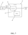
- FIG. 7 is a simplified block diagram illustrating an example system for receiving sensor input from the control panel of FIG. 2 and providing component control signals in accordance with embodiments of the disclosure.
- FIG. 8 is a flow chart illustrating an example method of providing control signals to control a component in accordance with embodiments of the disclosure.
- Embodiments of the invention may provide apparatus, systems, and methods for reconfigurable control panels.
- user interactive controls associated with components of a vehicle may be provided on a control surface of a vehicle and may be selectable and moveable by the user of the vehicle.
- the control interface may include tiles that may be selectively mounted on a control cluster or control panel, such as a center console of a vehicle.
- the tiles may have an indicia disposed thereon for identification of the tile.
- a user may touch or gesture in proximity of one or more of the tiles to activate or control components associated with the tile.
- the mounted tiles may be free of electrical connections.
- the selection of one or more of the tiles may be detected using a sensor, such as an image sensor.
- Signals from the sensor may be provided to a system that interprets the signal to determine a control function intended by the user of the control panel.
- the system may detect the presence of an object, such as a user's finger, in proximity of one or more tiles and determine a control function and associated signal based thereon and provide the same to a component of the vehicle.
- an initial presence of an object, such as a user's finger, in proximity of one or more tiles may be followed by detecting a movement of the object to determine a control signal for one or more components of the vehicle.
- control surfaces of the vehicle may be completely passive. All the controls may be interpreted by computer vision. Therefore, no mechanical switches, dials, electronics associated with sensing the actuation of a mechanical switch or dial, or the like may be needed. As a result, configurable control clusters may reduce the cost of any one or more of the control clusters, control infrastructure, the dashboard, or the vehicle.
- an vehicle cockpit 100 may include a dashboard 102 , steering wheel 104 , seats 106 , and a center arm rest 108 .
- a control panel such as a center console 120 that may include a front face 124 .
- the center console 120 may further include an illumination source 130 and an image sensor 134 .
- a user of the vehicle such as the driver of the vehicle, wishes to control components of the vehicle, such as a radio system or a heater, the user may interact with the center console 120 to effect such controls.
- the vehicle can include, but is not limited to, a car, a truck, a light-duty truck, a heavy-duty truck, a pickup truck, a minivan, a crossover vehicle, a van, a commercial vehicle, a private vehicle, a sports utility vehicle, a tractor-trailer, an aircraft, an airplane, a jet, a helicopter, a space vehicle, a watercraft, or any other suitable vehicle having a relatively closed cockpit.
- control elements of the vehicle are shown as a center console, control panels, or even single controls may be provided on any of the surfaces of the interior of the vehicle.
- a control surface may be provided on any one of the dashboard 102 , the steering wheel 101 , the seats 106 , the center arm rest 108 , the doors (not shown), or the like.
- an illustrative center console 120 may include a front surface 138 of the front face 124 and a plurality of control tiles 140 , 150 , 160 , 170 , 180 , and 190 mounted thereon.
- Each tile 140 , 150 , 160 , 170 , 180 , and 190 may have a front surface 142 , 152 , 162 , 172 , 182 , and 192 , respectively, with an indicia 146 , 156 , 166 , 176 , 186 , and 196 , respectively, provided thereon.
- the indicia 146 , 156 , 166 , 176 , 186 , and 196 may be indicative of a respective corresponding functionality of each of the tiles 140 , 150 , 160 , 170 , 180 , and 190 .
- the thermometer indicia 116 of tile 140 may be indicative of a heater of the vehicle. Therefore, the tile 140 when mounted on the center console 120 may be associated with controlling the heater of the vehicle.
- tile 150 may be associated with a sound system of the vehicle
- tile 160 may be associated with a cellular telephone of the user
- tile 170 may be associated with a defroster system 180 may be associated with a Bluetooth® controller
- tile 190 may be associated with an air conditioning system.
- the center console 120 , tiles 140 , 150 , 160 , 170 , 180 , and 190 , and the associated indicia 146 , 156 , 166 , 176 , 186 , and 196 may take any suitable shape and may be associated with any number of different controls provided to an occupant of a vehicle.
- Each of the tiles 140 , 150 , 160 , 170 , 180 , and 190 may further have a physical marker, such as a ridge 148 , 158 , 168 , 178 , 188 , and 198 extending from the front surfaces 142 , 152 , 162 , 172 , 182 , and 192 , respectively.
- the physical marker 148 , 158 , 168 , 178 , 188 , and 198 may be indicative of the respective corresponding functionality of each of the tiles 140 , 150 , 160 , 170 , 180 , and 190 to the hardware and systems associated with the center console 120 , as will be described with reference to FIGS. 6-8 .
- the ridges 148 , 158 , 168 , 178 , 188 , and 198 may be indicative of the functions and controls to which the respective tiles 140 , 150 , 160 , 170 , 180 , and 190 of the control panel 120 are associated.
- Each of the ridges 148 , 158 , 168 , 178 , 188 , and 198 may be unique and therefore may be uniquely identified with its respective tile 140 , 150 , 160 , 170 , 180 , and 190 , as well as functions and components associated therewith.
- the ridges 148 , 158 , 168 , 178 , 188 , and 198 may have unique size, length, shape, protrusion from the respective front surface 142 , 152 , 162 , 172 , 182 , and 192 , or combinations thereof. As depicted in FIG. 2 , each of the ridges 148 , 158 , 168 , 178 , 188 , and 198 have a unique length and therefore may be identified by their unique length. For example, the ridge 148 may indicate that the tile 140 when mounted on the center console 120 may be associated with controlling the heater of the vehicle.
- ridge 158 may indicate that tile 150 may be associated with the sound system of the vehicle
- ridge 168 may indicate that tile 160 may be associated with the cellular telephone of the user
- ridge 178 may indicate that tile 170 may be associated with the defroster system
- ridge 188 may indicate that tile 180 may be associated with the Bluetooth® controller
- ridge 198 may indicate that tile 190 may be associated with the air conditioning system.
- the ridges 148 , 158 , 168 , 178 , 188 , and 198 may be of dissimilar lengths on each of the tiles 140 , 150 , 160 , 170 , 180 , and 190 . Further, in certain embodiments, the ridges 148 , 158 , 168 , 178 , 188 , and 198 may be of dissimilar heights, or extensions form the front surface 142 , 152 , 162 , 172 , 182 , and 192 on each of the tiles 140 , 150 , 160 , 170 , 180 , and 190 .
- the front surface 142 , 152 , 162 , 172 , 182 , and 192 on each of the tiles 140 , 150 , 160 , 170 , 180 , and 190 may be substantially flush with the front surface 140 of the center console 120 .
- the front surfaces 142 , 152 , 162 , 172 , 182 , and 192 may protrude out above or be recessed relative to the front surface 140 of the center console 120 .
- the illumination source 130 and the image sensor 134 may be provided near a top end of the front face 124 of the center console 120 . In other embodiments, the illumination source 130 and the image sensor 134 may be provided at any suitable position relative to the front face 124 of the center console 120 . For example, the illumination source 130 and the image sensor 134 may be located near a bottom or side ends of the front face 124 of the center console 120 . As further alternatives, the illumination source 130 and the image sensor 134 may be placed at different sides of the front face 124 of the center console 120 .
- the illumination source 130 may include an optical source 200 and an optical element 202 to generate an illumination plane or laser plane bound by the edges 210 .
- the optical source 200 may be an emitter of coherent radiation, such as a light amplification by stimulated emission of radiation (laser) device emitting a laser beam at one or more wavelengths.
- the wavelengths may be, for example, in the infrared region of the spectrum and therefore not visible to a user of the center console 120 .
- the wavelength may be in the near near-ultraviolet (UV) range.
- the wavelength of the optical source 200 may be provided in the visible range of about 380 nm to about 750 nm.
- the optical source 200 may be any known coherent radiation source including, but not limited to diode lasers, quantum well lasers, solid state lasers, gas lasers, or combinations thereof.
- the optical source 200 may not be a source of coherent radiation.
- the optical source 200 may be a light emitting diode (LED) emitting radiation at any variety of wavelengths.
- LED light emitting diode
- the optical element 202 may be any variety or combination of lenses, reflectors, or waveguides. In certain aspects, the optical element 202 may be able to provide a radiation plane from a point or near-point optical source 200 . In certain embodiments, the optical element 202 may be a Fresnel lens that provides a relatively wide dispersion of optical output from a relatively narrow optical input. In certain other embodiments, the optical element 202 may be a cylindrical lens that provides a relatively planar optical output from a relatively point-like optical source 200 . In certain further embodiments, the optical element 202 may be a mechanical element that rasters or scans the output from the optical source to provide an laser plane.
- the laser plane may be in proximity to all of the tiles 140 , 150 , 160 , 170 , 180 , and 190 on the front face 124 .
- the field of view of the image sensor 134 may also be able to view all of the tiles 140 , 150 , 160 , 170 , 180 , and 190 on the front face 124 .
- the laser plane may be in proximity of the front surface 142 , 152 , 162 , 172 , 182 , and 192 on each of the tiles 140 , 150 , 160 , 170 , 180 , and 190 and the field of view of the image sensor may be such that the image sensor may detect light originating from near the front surface 142 , 152 , 162 , 172 , 182 , and 192 on each of the tiles 140 , 150 , 160 , 170 , 180 , and 190 .
- the image sensor 134 may be any known device that converts an optical image or optical input to an electronic signal.
- the image sensor 134 may be of any suitable variety including a charge coupled device (CCD), complementary metal oxide semiconductor (CMOS) sensors, or the like.
- CMOS complementary metal oxide semiconductor
- the image sensor 134 may further be of any pixel count and aspect ratio.
- the image sensor 134 may be sensitive to any frequency of radiation, including infrared, visible, or near-UV. In one aspect, the image sensor 134 has a frequency range of sensitivity that includes the frequency of the illumination source 130 .
- While six tiles 140 , 150 , 160 , 170 , 180 , and 190 are shown mounted to the front face 124 of the center console 120 , there may be any number of tiles. Furthermore, there may be any amount of spacing between tiles in the vertical, horizontal, or diagonal directions in accordance with embodiments of the disclosure. As a non limiting example, in certain embodiments, there may be nine tiles arranged in a three tile by three tile arrangement. Additionally, the tiles 140 , 150 , 160 , 170 , 180 , and 190 may be of any suitable shape.
- illumination sources 130 and image sensors 134 there may be any number of illumination sources 130 and image sensors 134 .
- the tiles 140 , 150 , 160 , 170 , 180 , and 190 may be mounted, or “snapped-on” to the front face 124 of the center console 120 in recesses 220 within the front face 124 .
- the recesses 220 may have sidewalls 222 with indentations 224 therein.
- Each of the tiles 140 , 150 , 160 , 170 , 180 , and 190 may have a sidewall 230 with tabs 232 extending therefrom.
- the user may insert the tile 140 , 150 , 160 , 170 , 180 , and 190 into the cavity 220 in a manner such that the tabs 232 engage with the indentations 224 to hold the tile 140 , 150 , 160 , 170 , 180 , and 190 in place on the front face 124 .
- the center console 120 can be reconfigured by removing, adding, or rearranging tiles 140 , 150 , 160 , 170 , 180 , and 190 on the front face 124 .
- the user such as the driver of the vehicle, may move one or more tiles 140 , 150 , 160 , 170 , 180 , and 190 to locations on the front face 124 to create a center console 120 configuration that may be convenient to the user. Therefore, using the center console 120 in combination with the control tiles 140 , 150 , 160 , 170 , 180 , and 190 , the resulting control panels, control clusters, and control surfaces may be reconfigurable.
- a driver may decide to place the tile 190 corresponding to the air conditioner in relatively close proximity to the driver or in an otherwise convenient location on the front face 124 relative to the heater tile 140 during the summer, when the air conditioner may be used more frequently than the heater.
- the same driver may decide to place the heater tile 140 in relatively close proximity to the driver or in an otherwise convenient location on the front face 124 relative to the air conditioning tile 140 during the winter when the heater may be used more frequently than the air conditioner.
- the center console 120 As another non-limiting example of reconfiguring the center console 120 , consider a user that prefers to use a cellular telephone in the vehicle rather than listening to the radio. The user may choose to place the telephone tile 160 in a more convenient location on the center console 120 than the music tile 150 . There may be a different user that prefers to listen to music, rather than using a cellular telephone in the vehicle while driving. This second user may place may choose to place the music tile 150 in a more convenient location on the center console 120 than the telephone tile 160 .
- the center console 120 and control panels in general, within a vehicle may be reconfigured and customized based at least in part on user preferences and behavior, environmental factors, or components available on the vehicle.
- a user may not include a Bluetooth® tile 190 on the center console 120 , if the vehicle does not have a Bluetooth controller component.
- the control panels with tiles 140 , 150 , 160 , 170 , 180 , and 190 as disclosed herein, one does not have to use a predetermined control layout as provided by the manufacturer of the vehicle.
- One can customize the control panel to one's convenience.
- manufacturers may provide a pre-set list of potential functionality that the driver or user may assign to the tiles. Therefore a reconfigurable control surface may provide greater convenience, safety, usability, and lower cost, relative to predetermined and non-configurable control surfaces.
- the tiles 140 , 150 , 160 , 170 , 180 , and 190 may be constructed using lightweight thermoplastic materials such as polyethylene terephthalate (PET), poly-vinyl chloride (PVC), polytetrafluoroethylene (PTFE), polymethyl methacrylate (PMMA or acrylic glass), polyethylene (PE), or the like.
- the tiles 140 , 150 , 160 , 170 , 180 , and 190 may be formed by molding processes, such as injection molding.
- the tiles 140 , 150 , 160 , 170 , 180 , and 190 may be formed using extrusion processes.
- the use of various polymeric materials, including thermoplastic and thermosetting plastics, may provide for an appealing tactile and aesthetic appearance.
- tiles 140 , 150 , 160 , 170 , 180 , and 190 constructed from plastic materials may be formed relatively inexpensively and may provide for a relatively high level of durability, especially within the interior of a vehicle, where the tiles 140 , 150 , 160 , 170 , 180 , and 190 may experience extreme temperatures in certain geographies and seasons.
- Tiles 140 , 150 , 160 , 170 , 180 , and 190 may alternatively be formed using other non-plastic materials including, but not limited to metals, glass, ceramics, natural fibers, wood, paper, cardboard, composites, or combinations thereof.
- the tiles may be formed from metals using stamping processes.
- a particular look or finish may be desired where tiles of a particular construct may be desired. For example, if a vehicle interior has a brushed nickel finish, it may be desirable to construct the tiles 140 , 150 , 160 , 170 , 180 , and 190 using metal, since other materials, such as wood or plastic, may clash with the overall styling or aesthetics of the vehicle interior.
- the tiles 140 , 150 , 160 , 170 , 180 , and 190 may be obtained by the end user, such as the driver of the vehicle, from the manufacturer or dealer of the vehicle. Other tiles may be obtained by the user or provided by a third party.
- the heater tile 140 may be provided by the vehicle manufacturer to control a component of the vehicle, namely the heater, that is sold as a component of a new vehicle.
- the cellular telephone tile 160 may be one that is provided to the user separately from the vehicle.
- the cellular telephone tile 160 may be provided by a manufacturer of the cellular telephone or the cellular service provider.
- an end user may acquire control tiles 140 , 150 , 160 , 170 , 180 , and 190 from various sources for the control of various components.
- tiles may be procured with a choice of types. For example, one may procure a wood, metal, or plastic tile for the same control function depending on the look and finish of the user's vehicle.
- tiles may be in any suitable form, including, but not limited to, knobs, dials, sliders, or ridged surfaces. Certain forms of tiles may provide for an appealing tactile experience. In one aspect, such tiles may mimic active dials that users may be familiar with, but may be passive in nature. Furthermore, the tiles of various forms may, in certain embodiments, provide haptic feedback, such as vibration or rumbling. It should also be appreciated that the tiles may be mounted to the control panel 120 using any suitable elements for mounting including, but not limited to, magnetic mounting, hook and loop fasteners, such as Velcro®, mechanical fasteners, screws, allen screws, nails, bosses, adhesives, or combinations thereof.
- a laser plane 240 as emitted by the illumination source 130 , is shown above and in close proximity of the tiles 170 , 180 , and 190 , along with the front surface 138 of the center console 120 .
- optical scattering 250 of some of the light projected in the laser plane 240 may result.
- the scattered light may in turn be detected by the image sensor 134 and in turn produce a signal indicative of the scattered light.
- the image sensor may generate an image and a corresponding image signal that incorporates each of the ridges 178 , 188 , and 198 corresponding to tiles 170 , 180 , and 190 , respectively, as well as the optical scatter 250 resulting from reflections from the finger 244 .
- each of the ridges 178 , 188 , and 198 may be unique and therefore distinguishable from each other.
- the unique ridges 178 , 188 , and 198 may further be used to identify the corresponding tiles 170 , 180 , and 190 .
- the position of the optical scatter 250 relative to each of the ridges 176 , 186 , and 196 may be ascertained from the image sensor signal.
- the position of the finger 244 may be ascertained relative to the ridges 178 , 188 , and 198 based on the image signal provided by the image sensor. If the ridges 178 , 188 , and 198 can further be attributed to a particular functionality, it may be possible to determine a functionality of a component that corresponds to the touching of a particular tile 170 , 180 , and 190 with the finger 244 .
- the image sensor 134 may provide an image sensor signal repeatedly to show movement of the finger 244 .
- the image sensor 134 may be able to detect a tapping, such as a double tap, of the finger 244 on the surface of a tile, such as tile 150 .
- a double tap after selecting one of the tiles, such as tile 150 may be indicative of a particular functionality of a component associated with the particular tile.
- a double tap of the music tile 150 may be indicative of toggling, or turning on or turning off, of music. Therefore, one may first select the music tile 150 by touching the front surface 152 of the tile 150 , followed by double tapping the front surface 152 to indicate a desire to turn on the music.
- the repeated sampling by the image sensor 134 at a particular frame rate may enable detecting various other movements of the finger 144 .
- the image sensor 134 may be able to detect a finger movement down as indicated by arrow 260 , a finger movement up as indicated by arrow 262 , a movement left as indicated by arrow 264 , a movement right as indicated by arrow 266 , a movement in a counter-clockwise direction as indicated by arrow 268 , and a movement in a clockwise direction as indicated by arrow 270 .
- Each of these finger 244 movements may be indicative of a particular functionality associated with a particular the that is desired by the user of the center console 120 .
- the user may provide additional commands based on further movement of the user's finger 244 .
- a down movement 260 may be associated, for example, with a decrease in volume of the music.
- an up movement may be associated with an increase in the volume of the music.
- the side to side movements 264 and 266 may be used to change the speaker balance of the music or provide frequency discriminating equalization of the music.
- the counter clockwise 268 and clockwise 270 movements may be used to tune a radio or jog through a music playlist to select a particular song.
- finger 134 movements may be translated into controls for components in a variety of contexts.
- particular finger 244 movements may increase or decrease the temperature of the heater system or set the velocity of forced air for the air conditioning system.
- the system 280 may include one or more processors 284 communicatively coupled to an electronic memory 286 via a communicative link 290 .
- the one or more processors 284 may further be communicatively coupled to the image sensor 134 and receive image sensor signals generated by the image sensor 134 .
- the one or more processors 284 may include, without limitation, a central processing unit (CPU), a digital signal processor (DSP), a reduced instruction set computer (RISC), a complex instruction set computer (CISC), a microprocessor, a microcontroller, a field programmable gate array (FPGA), or any combination thereof.
- the system 280 may also include a chipset (not shown) for controlling communications between the processor(s) 284 and one or more of the other components of the system 280 .
- the system 280 may be based on an Intel® Architecture system and the one or more processors 284 and chipset may be from a family of Intel® processors and chipsets, such as the Intel® Atom® processor family.
- the one or more processors 284 may also include one or more application-specific integrated circuits (ASICs) or application-specific standard product (ASSPs) for handling specific data processing functions or tasks.
- ASICs application-specific integrated circuits
- ASSPs application-specific standard product
- the memory 286 may include one or more volatile and/or non-volatile memory devices including, but not limited to, random access memory (RAM), dynamic RAM (DRAM), static RAM (SRAM), synchronous dynamic RAM (SDRAM), double data rate (DDR) SDRAM (DDR-SDRAM), RAM-BUS DRAM (RDRAM), flash memory devices, electrically erasable programmable read only memory (EEPROM), non-volatile RAM (NVRAM), universal serial bus (USB) removable memory, or combinations thereo.
- RAM random access memory
- DRAM dynamic RAM
- SRAM static RAM
- SDRAM synchronous dynamic RAM
- DDR double data rate SDRAM
- RDRAM RAM-BUS DRAM
- flash memory devices electrically erasable programmable read only memory (EEPROM), non-volatile RAM (NVRAM), universal serial bus (USB) removable memory, or combinations thereo.
- EEPROM electrically erasable programmable read only memory
- NVRAM non-volatile RAM
- USB universal serial bus
- the one or more processors 284 may be part of an in-vehicle infotainment (IVI) system. In other embodiments the one or more processors 284 may be dedicated to the system 280 for providing component control signals. Therefore, in such embodiments, the system 280 is separate from the IVI system. However, the system 280 may optionally communicate with the IVI system of the vehicle. It should also be noted that the system 280 may be part of or otherwise associated with a main computer of the vehicle.
- IVI in-vehicle infotainment
- the software associated with the system 280 may further be stored on a server or a cloud server and may be transferred to the system 280 of the vehicle via one or more of a wired connection, a wireless connection, a smart key, a universal serial bus (USB) drive, or the like.
- a wired connection a wireless connection
- a smart key a smart key
- USB universal serial bus
- the one or more processors 284 may receive image sensor signals from the image sensor 134 .
- the image sensor signal may be provide information on the location of an object, such as a finger 244 , relative to one or more tiles 140 , 150 , 160 , 170 , 180 , and 190 . Therefore, the one or more processors 284 may analyze the image sensor signal to determine if a user has touched one or more of the tiles 140 , 150 , 160 , 170 , 180 , and 190 .
- the determination may be made by analyzing the location of optical scattering 250 from the finger 244 perturbing the laser plane 240 relative to the location of one or more of the physical markers in the form of tactile ridges 148 , 158 , 168 , 178 , 188 , and 198 provided on each of the tiles 140 , 150 , 160 , 170 , 180 , and 190 .
- the one or more processors may determine that the user intended to touch the Bluetooth® controller tile 180 .
- the electronic memory 286 may store software programs or other instruction sets, that when run on the one or more processors 284 , enables the determination of the tiles that were touched by the finger 244 based upon the image sensor signal provided by the image sensor 134 .
- the software and programs, as stored on the electronic memory 286 may incorporate additional logic for ascertaining if a touch by the user's finger 244 was intentional. In certain cases, especially in a vehicle setting, one may touch one or more of the tiles 140 , 150 , 160 , 170 , 180 , and 190 unintentionally. For example, if a user's finger 244 is close to the center console 120 and the vehicle travels over a bump, the finger may accidentally touch one or more of the tiles 140 , 150 , 160 , 170 , 180 , and 190 of the center console 120 .
- the one or more processors may additionally analyze the movement of the finger 244 to determine if a touch event was intentional. For example, if the one or more processors 284 , based on the image sensor signal, detects a touch by the finger 244 , but subsequent to the touch, detects erratic movement of the finger 244 , then the one or more processors may deem the initial touch event to be unintentional and ignore the same.
- the erratic movement may involve the finger 244 moving in one or more unexpected directions at a relatively high velocity followed by a relatively high deceleration of the finger 244 .
- the one or more processors 284 may detect other erratic movements that may be symptomatic of the finger 244 accidentally touching the center console 120 due to movement of the vehicle.
- the one or more processors 284 may continue to determine the location of the finger 244 relative to the front face 124 of the center console 120 .
- the one or more processors 284 may be “observing” the movement of the finger 244 by tracking the movement of the optical scattering 250 to determine a user desired control action. For example, if the one or more processors 284 determine that the finger 244 intentionally touched the air conditioner tile 190 , then the one or more processors 284 may analyze subsequent movement of the finger to detect one or more pre-expected movements, such as the double tap, down 260 , up 262 , left 264 , right 266 , counter clockwise 268 , or clockwise 270 movement. The one or more processors 284 may determine a control action based upon the detected pre-expected movement. For example, if the left movement 264 , the one or more processors may interpret that the user desires the thermostat temperature of the air conditioner to be reduced.
- the one or more processors 284 may generate a control signal for the same.
- the one or more processors may subsequently provide the control signal directly to the component or to a vehicle computer that can subsequently control the component based on the component control signal generated by the one or more processors 284 .
- the one or more processors 284 may generate a control signal for the air conditioner that controls the air conditioner to lower the temperature setting.
- the control signals linked to each of the components may be stored on the electronic memory 286 for access by the one or more processors.
- control signals may be stored on the electronic memory 286 organized as a lookup table. For example, if the one or more processors 284 decipher an intended control action by a user based upon the image sensor signal, the one or more processors 284 may access the electronic memo 286 to access the component control signals associated with the control action.
- the control system shown herein for the control of components of the vehicle requires fewer electrical wiring and connectors compared to non-configurable and wired control schemes.
- the tiles 140 , 150 , 160 , 170 , 180 , and 190 are not directly or indirectly coupled electrically to the components to which they correspond. This is quite different from non-configurable control panels where one or more switches may be electrically coupled either directly or indirectly to corresponding components with the use of conductive elements, such as connectors, wires, circuit boards, and the like. Therefore, the reconfigurable control panels, as disclosed herein, may have fewer electrical and mechanical elements that can fail during use and may provide a relatively cost effective and streamlined solution to controlling components of a vehicle.
- the manufacture of the reconfigurable center console 120 may have a relatively reduced bill of materials in comparison to non-configurable control panels.
- the reconfigurable center console 120 may have relatively fewer elements that can fail and therefore may be easier to troubleshoot and repair than a non-configurable control panel.
- the reconfigurable center console 120 be relatively lighter than non-reconfigurable control panels and therefore may result in fuel savings during the operation of the vehicle.
- the control panel is monitored.
- the control panel may be monitored by the image sensor 134 .
- the image sensor 134 may detect any optical scattering 250 from a laser plane 240 generated by the illumination source 130 and in proximity of the front face 124 of the center console 120 .
- this determination may require the one or more processors 284 to monitor the image sensor signal and determine if a optical scattering 250 from the laser plane 240 is detected.
- the one or more processors may further determine if touching of the tile 140 , 150 , 160 , 170 , 180 , and 190 by a user was intended, as discussed in reference to FIG. 7 .
- the method 300 returns to block 302 and continues to monitor the control panel. If however, it is determined at block 304 that a tile 140 , 150 , 160 , 170 , 180 , and 190 has been touched, then at block 306 , it is determined which tile has been touched.
- the determination of which tile has been touched may entail the one or more processors comparing the location of a detected optical scattering 250 to the location of physical markers, such as tactile ridges 148 , 158 , 168 , 178 , 188 , and 198 corresponding to each of the tiles 140 , 150 , 160 , 170 , 180 , and 190 .
- the one or more processors may determine the accessed tile 140 , 150 , 160 , 170 , 180 , and 190 as the tile with corresponding ridge 148 , 158 , 168 , 178 , 188 , and 198 most proximal to the optical scattering 250 .
- other algorithms may be used to ascertain the tile 140 , 150 , 160 , 170 , 180 , and 190 that has been touched.
- the motion of the finger may be monitored at block 308 .
- the motion of the finger 244 may be monitored by the image sensor 134 repeatedly imaging the proximity of the control panel and providing the resulting image sensor signals to the one or more processors 284 .
- the one or more processors 284 may be able to track the motion of the finger 244 with a precision in the range of about 2 millimeters (mm) to about 200 mm.
- the one or more processors 284 may further analyze the motion of the finger 244 and determine a movement associated therewith, such as a double tap, down 260 , up 262 , left 264 , right 266 , counter clockwise 268 , clockwise 270 , or the like.
- the finger 244 motion monitored corresponds to an intended control action. For example, if a particular motion, as monitored at block 308 , corresponds to an available action of a component corresponding to the tile 140 , 150 , 160 , 170 , 180 , and 190 selected at block 306 , then it would be determined that the monitored motion does correspond to an intended control action.
- the method 300 notifies the user that the motion was not recognized at block 312 and returns to block 302 to continue monitoring the control panel.
- the notification may be by any known mechanism, including in the form of a display message, such as on an electronic display or in the form of an audio notification, such as through speakers located within the cockpit 100 of the vehicle.
- the method proceeds to generate control signals to control a component according to the control action.
- the control action may be determined by utilizing a database of control actions stored in the electronic memory 286 of the system 280 .
- the generated control signals may further be provided to the corresponding component of the vehicle.
- method 300 may be modified in various ways in accordance with certain embodiments of the disclosure. For example, one or more operations of method 300 may be eliminated or executed out of order in other embodiments of the disclosure. Additionally, other operations may be added to method 300 in accordance with other embodiments of the disclosure.
- Embodiments described herein may be implemented using hardware, software, and/or firmware, for example, to perform the methods and/or operations described herein. Certain embodiments described herein may be provided as a tangible machine-readable medium storing machine-executable instructions that, if executed by a machine, cause the machine to perform the methods and/or operations described herein.
- the tangible machine-readable medium may include, but is not limited to, any type of disk including floppy disks, optical disks, compact disk read-only memories (CD-ROMs), compact disk rewritable (CD-RWs), and magneto-optical disks, semiconductor devices such as read-only memories (ROMs), random access memories (RAMs) such as dynamic and static RAMs, erasable programmable read-only memories (EPROMs), electrically erasable programmable read-only memories (EEPROMs), flash memories, magnetic or optical cards, or any type of tangible media suitable for storing electronic instructions.
- the machine may include any suitable processing or computing platform, device or system and may be implemented using any suitable combination of hardware and/or software.
- the instructions may include any suitable type of code and may be implemented using any suitable programming language.
- machine-executable instructions for performing the methods and/or operations described herein may be embodied in firmware.
Landscapes
- Engineering & Computer Science (AREA)
- Chemical & Material Sciences (AREA)
- Combustion & Propulsion (AREA)
- Transportation (AREA)
- Mechanical Engineering (AREA)
- General Engineering & Computer Science (AREA)
- Theoretical Computer Science (AREA)
- Human Computer Interaction (AREA)
- Physics & Mathematics (AREA)
- General Physics & Mathematics (AREA)
- User Interface Of Digital Computer (AREA)
Applications Claiming Priority (1)
| Application Number | Priority Date | Filing Date | Title |
|---|---|---|---|
| PCT/US2011/067857 WO2013101074A1 (en) | 2011-12-29 | 2011-12-29 | Configurable control panels |
Publications (2)
| Publication Number | Publication Date |
|---|---|
| US20140297105A1 US20140297105A1 (en) | 2014-10-02 |
| US9321349B2 true US9321349B2 (en) | 2016-04-26 |
Family
ID=48698310
Family Applications (1)
| Application Number | Title | Priority Date | Filing Date |
|---|---|---|---|
| US13/977,598 Active US9321349B2 (en) | 2011-12-29 | 2011-12-29 | Configurable control panels |
Country Status (3)
| Country | Link |
|---|---|
| US (1) | US9321349B2 (zh) |
| CN (1) | CN104010864B (zh) |
| WO (1) | WO2013101074A1 (zh) |
Cited By (4)
| Publication number | Priority date | Publication date | Assignee | Title |
|---|---|---|---|---|
| US20170169963A1 (en) * | 2015-12-15 | 2017-06-15 | John Schlick | Light switch indicator |
| US20170238395A1 (en) * | 2015-05-26 | 2017-08-17 | Lutron Electronics Co., Inc. | Control device having an integral reflecting structure for a sensing circuit |
| US11364857B2 (en) | 2019-01-31 | 2022-06-21 | Toyota Motor Engineering & Manufacturing North America, Inc. | Modular interior vehicle electronics system |
| US11472259B2 (en) * | 2017-09-14 | 2022-10-18 | Hyundai Motor Company | System and method for controlling air conditioning and ISG systems for vehicle |
Families Citing this family (6)
| Publication number | Priority date | Publication date | Assignee | Title |
|---|---|---|---|---|
| CN104010864B (zh) | 2011-12-29 | 2016-10-26 | 英特尔公司 | 可配置控制面板 |
| US10996841B2 (en) * | 2013-03-15 | 2021-05-04 | Volkswagen Ag | Interactive sliding touchbar for automotive display |
| DE102014202834A1 (de) * | 2014-02-17 | 2015-09-03 | Volkswagen Aktiengesellschaft | Anwenderschnittstelle und Verfahren zum berührungslosen Bedienen eines in Hardware ausgestalteten Bedienelementes in einem 3D-Gestenmodus |
| DE102014009607A1 (de) * | 2014-06-27 | 2015-12-31 | Audi Ag | Kraftfahrzeug-Bedienkonsolen mit modellübergreifender Bedienhilfe |
| FR3028628B1 (fr) | 2014-11-19 | 2017-06-09 | Manitou Bf | Dispositif et systeme de commande de fonctions de vehicule industriel ou tout terrain |
| EP3225458B1 (de) * | 2016-04-01 | 2018-12-12 | Grammer Ag | Bedienelemente in einer armlehnenvorrichtung |
Citations (10)
| Publication number | Priority date | Publication date | Assignee | Title |
|---|---|---|---|---|
| JPS61200718A (ja) | 1985-03-04 | 1986-09-05 | Casio Comput Co Ltd | 電子機器の光学的入力装置 |
| JPS6237231A (ja) | 1985-08-09 | 1987-02-18 | Tokai Rika Co Ltd | 自動車用スイツチ操作表示装置 |
| JPH02189834A (ja) | 1989-01-18 | 1990-07-25 | Omron Tateisi Electron Co | 反射型光電スイッチ |
| US20020061217A1 (en) * | 2000-11-17 | 2002-05-23 | Robert Hillman | Electronic input device |
| US6593530B2 (en) | 2001-07-26 | 2003-07-15 | Torrence L. Hunt | Electrical switch identification plate with replaceable insert members |
| US20070013662A1 (en) * | 2005-07-13 | 2007-01-18 | Fauth Richard M | Multi-configurable tactile touch-screen keyboard and associated methods |
| US20100127847A1 (en) * | 2008-10-07 | 2010-05-27 | Cisco Technology, Inc. | Virtual dashboard |
| CN101801706A (zh) | 2007-09-14 | 2010-08-11 | 德尔菲技术公司 | 用于车载仪表的控制面板 |
| US7821718B1 (en) * | 2009-04-06 | 2010-10-26 | Hewlett-Packard Development Company, L.P. | Laser line generator |
| WO2013101074A1 (en) | 2011-12-29 | 2013-07-04 | Intel Corporation | Configurable control panels |
Family Cites Families (1)
| Publication number | Priority date | Publication date | Assignee | Title |
|---|---|---|---|---|
| CN201600575U (zh) * | 2009-12-08 | 2010-10-06 | 长安大学 | 一种用于汽车模拟驾驶器的基于图像处理的虚拟按钮装置 |
-
2011
- 2011-12-29 CN CN201180076053.6A patent/CN104010864B/zh active Active
- 2011-12-29 WO PCT/US2011/067857 patent/WO2013101074A1/en active Application Filing
- 2011-12-29 US US13/977,598 patent/US9321349B2/en active Active
Patent Citations (10)
| Publication number | Priority date | Publication date | Assignee | Title |
|---|---|---|---|---|
| JPS61200718A (ja) | 1985-03-04 | 1986-09-05 | Casio Comput Co Ltd | 電子機器の光学的入力装置 |
| JPS6237231A (ja) | 1985-08-09 | 1987-02-18 | Tokai Rika Co Ltd | 自動車用スイツチ操作表示装置 |
| JPH02189834A (ja) | 1989-01-18 | 1990-07-25 | Omron Tateisi Electron Co | 反射型光電スイッチ |
| US20020061217A1 (en) * | 2000-11-17 | 2002-05-23 | Robert Hillman | Electronic input device |
| US6593530B2 (en) | 2001-07-26 | 2003-07-15 | Torrence L. Hunt | Electrical switch identification plate with replaceable insert members |
| US20070013662A1 (en) * | 2005-07-13 | 2007-01-18 | Fauth Richard M | Multi-configurable tactile touch-screen keyboard and associated methods |
| CN101801706A (zh) | 2007-09-14 | 2010-08-11 | 德尔菲技术公司 | 用于车载仪表的控制面板 |
| US20100127847A1 (en) * | 2008-10-07 | 2010-05-27 | Cisco Technology, Inc. | Virtual dashboard |
| US7821718B1 (en) * | 2009-04-06 | 2010-10-26 | Hewlett-Packard Development Company, L.P. | Laser line generator |
| WO2013101074A1 (en) | 2011-12-29 | 2013-07-04 | Intel Corporation | Configurable control panels |
Non-Patent Citations (3)
| Title |
|---|
| International Preliminary Report on Patentability and Written Opinion received for PCT Patent Application No. PCT/US2011/067857, mailed on Jul. 10, 2014, 8 pages. |
| International Search Report and Written Opinion received for PCT Application No. PCT/US2011/067857, mailed on Sep. 5, 2012, 11 pages. |
| Office Action for Chinese Application No. 201180076053.6 mailed Nov. 25, 2015. 8 pages Chinese Office Action, 15 pages English Translation. |
Cited By (10)
| Publication number | Priority date | Publication date | Assignee | Title |
|---|---|---|---|---|
| US20170238395A1 (en) * | 2015-05-26 | 2017-08-17 | Lutron Electronics Co., Inc. | Control device having an integral reflecting structure for a sensing circuit |
| US10129951B2 (en) * | 2015-05-26 | 2018-11-13 | Lutron Electronics Co., Inc. | Control device having an integral reflecting structure for a sensing circuit |
| US10237949B1 (en) | 2015-05-26 | 2019-03-19 | Lutron Electronics Co., Inc. | Control device having an integral reflecting structure for a sensing circuit |
| US10492273B2 (en) | 2015-05-26 | 2019-11-26 | Lutron Technology Company Llc | Control device having an integral reflecting structure for a sensing circuit |
| US10820392B2 (en) | 2015-05-26 | 2020-10-27 | Lutron Technology Company Llc | Control device having an integral reflecting structure for a sensing circuit |
| US11317498B2 (en) | 2015-05-26 | 2022-04-26 | Lutron Technology Company Llc | Control device having an integral reflecting structure for a sensing circuit |
| US11889602B2 (en) | 2015-05-26 | 2024-01-30 | Lutron Technology Company Llc | Control device having an integral reflecting structure for a sensing circuit |
| US20170169963A1 (en) * | 2015-12-15 | 2017-06-15 | John Schlick | Light switch indicator |
| US11472259B2 (en) * | 2017-09-14 | 2022-10-18 | Hyundai Motor Company | System and method for controlling air conditioning and ISG systems for vehicle |
| US11364857B2 (en) | 2019-01-31 | 2022-06-21 | Toyota Motor Engineering & Manufacturing North America, Inc. | Modular interior vehicle electronics system |
Also Published As
| Publication number | Publication date |
|---|---|
| WO2013101074A1 (en) | 2013-07-04 |
| US20140297105A1 (en) | 2014-10-02 |
| CN104010864B (zh) | 2016-10-26 |
| CN104010864A (zh) | 2014-08-27 |
Similar Documents
| Publication | Publication Date | Title |
|---|---|---|
| US9321349B2 (en) | Configurable control panels | |
| US20170050523A1 (en) | Control panels | |
| US8766911B2 (en) | Multifunction display and operating device and method for operating a multifunction display and operating device having improved selection operation | |
| CN107150643B (zh) | 车辆及其控制方法 | |
| CN106476723B (zh) | 直观的车辆控制 | |
| CN104691450A (zh) | 用户接口 | |
| KR102049649B1 (ko) | 손가락 기반 컨트롤 바 및 상기 컨트롤 바의 사용 | |
| US20160054822A1 (en) | Input device | |
| US20150185834A1 (en) | System and method for gaze tracking | |
| US10983691B2 (en) | Terminal, vehicle having the terminal, and method for controlling the vehicle | |
| KR20150020225A (ko) | 차량의 에어컨디셔닝 장치를 조절하기 위한 조작 장치 및 이를 위한 방법 | |
| US20160054849A1 (en) | Motor vehicle operating device | |
| US20190042063A1 (en) | Vehicle-mounted equipment operation support system | |
| US20220407514A1 (en) | Switch device with integrated touch sensor | |
| KR20160099344A (ko) | 인터페이스 장치, 이와 연결되는 차량 검사 장치, 및 차량 검사 장치의 제어방법 | |
| KR102662152B1 (ko) | 표면 포장된 사용자 인터페이스 터치 제어기 | |
| KR101348198B1 (ko) | 차량용 멀티미디어 제어 장치 | |
| JP2015132905A (ja) | 電子システム、検出範囲の制御方法、及び制御プログラム | |
| KR20170097759A (ko) | 인포테인먼트 시스템, 운송 수단 및 운송 수단의 인포테인먼트 시스템을 조작하는 장치 | |
| US10739902B2 (en) | Input apparatus and control method of the same | |
| CN109814154B (zh) | 近距离传感器 | |
| CN104709198A (zh) | 用于通过机动车中的操作体操作机动车功能的装置和设备 | |
| KR102441509B1 (ko) | 단말기, 차량 및 단말기 제어방법 | |
| CN110870204B (zh) | 用于机动车的操作设备,用于借助于操作设备运行机动车的方法,控制装置和机动车 | |
| JP2014020073A (ja) | 制御装置 |
Legal Events
| Date | Code | Title | Description |
|---|---|---|---|
| AS | Assignment |
Owner name: INTEL CORPORATION, CALIFORNIA Free format text: ASSIGNMENT OF ASSIGNORS INTEREST;ASSIGNORS:GRAUMANN, DAVID L.;HEALEY, JENNIFER;SIGNING DATES FROM 20120604 TO 20120823;REEL/FRAME:028905/0559 |
|
| STCF | Information on status: patent grant |
Free format text: PATENTED CASE |
|
| MAFP | Maintenance fee payment |
Free format text: PAYMENT OF MAINTENANCE FEE, 4TH YEAR, LARGE ENTITY (ORIGINAL EVENT CODE: M1551); ENTITY STATUS OF PATENT OWNER: LARGE ENTITY Year of fee payment: 4 |
|
| MAFP | Maintenance fee payment |
Free format text: PAYMENT OF MAINTENANCE FEE, 8TH YEAR, LARGE ENTITY (ORIGINAL EVENT CODE: M1552); ENTITY STATUS OF PATENT OWNER: LARGE ENTITY Year of fee payment: 8 |