US930105A - Door-fender. - Google Patents
Door-fender. Download PDFInfo
- Publication number
- US930105A US930105A US46596408A US1908465964A US930105A US 930105 A US930105 A US 930105A US 46596408 A US46596408 A US 46596408A US 1908465964 A US1908465964 A US 1908465964A US 930105 A US930105 A US 930105A
- Authority
- US
- United States
- Prior art keywords
- fender
- door
- roller
- face
- shank
- Prior art date
- Legal status (The legal status is an assumption and is not a legal conclusion. Google has not performed a legal analysis and makes no representation as to the accuracy of the status listed.)
- Expired - Lifetime
Links
- 239000002184 metal Substances 0.000 description 5
- 208000034656 Contusions Diseases 0.000 description 2
- 239000007787 solid Substances 0.000 description 2
- PIWKPBJCKXDKJR-UHFFFAOYSA-N Isoflurane Chemical compound FC(F)OC(Cl)C(F)(F)F PIWKPBJCKXDKJR-UHFFFAOYSA-N 0.000 description 1
- 241000220324 Pyrus Species 0.000 description 1
- 150000001875 compounds Chemical class 0.000 description 1
- 239000000463 material Substances 0.000 description 1
- 235000021017 pears Nutrition 0.000 description 1
- 230000000630 rising effect Effects 0.000 description 1
- 229940038570 terrell Drugs 0.000 description 1
- 239000002023 wood Substances 0.000 description 1
Images
Classifications
-
- E—FIXED CONSTRUCTIONS
- E05—LOCKS; KEYS; WINDOW OR DOOR FITTINGS; SAFES
- E05C—BOLTS OR FASTENING DEVICES FOR WINGS, SPECIALLY FOR DOORS OR WINDOWS
- E05C17/00—Devices for holding wings open; Devices for limiting opening of wings or for holding wings open by a movable member extending between frame and wing; Braking devices, stops or buffers, combined therewith
- E05C17/02—Devices for holding wings open; Devices for limiting opening of wings or for holding wings open by a movable member extending between frame and wing; Braking devices, stops or buffers, combined therewith by mechanical means
- E05C17/04—Devices for holding wings open; Devices for limiting opening of wings or for holding wings open by a movable member extending between frame and wing; Braking devices, stops or buffers, combined therewith by mechanical means with a movable bar or equivalent member extending between frame and wing
- E05C17/12—Devices for holding wings open; Devices for limiting opening of wings or for holding wings open by a movable member extending between frame and wing; Braking devices, stops or buffers, combined therewith by mechanical means with a movable bar or equivalent member extending between frame and wing consisting of a single rod
- E05C17/20—Devices for holding wings open; Devices for limiting opening of wings or for holding wings open by a movable member extending between frame and wing; Braking devices, stops or buffers, combined therewith by mechanical means with a movable bar or equivalent member extending between frame and wing consisting of a single rod sliding through a guide
- E05C17/203—Devices for holding wings open; Devices for limiting opening of wings or for holding wings open by a movable member extending between frame and wing; Braking devices, stops or buffers, combined therewith by mechanical means with a movable bar or equivalent member extending between frame and wing consisting of a single rod sliding through a guide concealed, e.g. for vehicles
Definitions
- My invention relates todoor fenders and more particularly to a fender which is adapted to be secured to a swinging door to protect the door itself from bruising or chafing contact with another swinging door or with the wall.
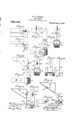
- a practical embodiment of my invention 1s represented ,in the accompanying drawings, in which-- Figure 1 is a view of the fender as it 'ap pears when attached to the upper free swinging corner of a door, Fig. 2-is a top plan view of the same, Fig. 3 is an enlarged top plan view of the fender in detail,'Fig. 4 is an end view of the same, Fig. 5 is a face new of the same, Fig. 6 is a top plan view of a fender showing a modified form, Fig.
- Fig. 7 is ah endview of the same
- Fig. 8 is'a face view of the same
- Fig. 9 is a-.plan view in detail of a modified form of adjustable shank and fender roller
- Fig. 10 is an edge iew of the same
- Fig. 11 is a'top plan viewof an other modified form showing the body of the fender in skeleton form
- Fig. 12 is an end view of the same
- Fig. 13 is a top plan View of a modified form in which the body is skeleton and the roller carrying shankis secured to the front instead of the end of the body
- Fig. 14 is a face view of the same.
- the body of the fender is denoted by 1 and may consist of a block of wood having its outer face. formed on a graceful compound curve, as shown at 2, gradually reducing the depth of the block so that a screw 3 may be passed through it into the block in position.
- a kerf or slot 5 (see Fig. extending back toward the screw 3, for instance to the dotted line 6, Fig.3, for the reception of the shank 7'of the fender roller support.
- This shank 7 may be held in position within the kerf 5 by frictional contact, the pressure of the oppo-' site walls of the kerf or slot 5 being increased at pleasure by means of a clamping screw 8 extending through one of the walls of the block 1 and screwed into the opposite wall.
- the fender roller holder may be formed conveniently of a thin strip of metal, the two parts of which are folded upon themselves to form the shank 7 and at their outer ends branch outwardly-to form the branches 9 and 10 between which the fender roller 11 is journaled by means of a spindle 12 passing centrally through the roller 11 and fastened in the branches 9 and 10.
- the roller 11 which maybe of rubber, felt or other suitable yielding material, will on ge any-obstruction to the swinging of the cor before the door itself strikes such obstruction and thus will fend it from any bruising pleasure by adjusting the shank 7 outwardly or inwardly within the kerf, 5 and pinching it inits adjusted position by means of the screw 8.
- the jsup: porting block may bemade solid as shown 11313, Figs. 6, 7 and 8, and the roller holder may be formed of a single strip of metal split at its outer endand the branches twisted, as .shown at 14, 15, Figs. 6, 7 and 8, to
- the strip of metal which forms the shank may be formed, as shown in Figs. 9 and 10, and
- the block which supports the roller holder may be made in skeleton form, as shown in Figs. 11 to 14:, inclusive, and in this instance may be formed of a thin piece of metal bent into triangular form and the holder for the fender roller holder may be provided with an elongatedslot 17 like those indicated inFigs. 6 to 10 inclusive, through which 'a screw 31 maybe passed to receive a locking nut 32 onthe inner face of either the end wall of the skeleton triangular body support 33.0r on the front or oblique faceof the said support, as shown in F1gs..13 and. 14;, as the case maybe.
- What I-claim is w 1.
- a fender comprising a body portion adapted to be secured to the face of a door, a fender roller, a'fender roller support, One of the parts, the body portion and, fender roller s'upport,being provided with a slot and a screw .coacting with the slot to hold the fender roller support in different adjustments toward and away from the face of the door.
- a fender comprising a body portion adapted to be secured, to the face of a door, the said body portion .being provi dednwith a kerf or'slot in its end, a tender roller, a support for the fender roller provided with a thin shank adapted to enter the kerf or slot in the-body portion and a screw forn -L" holding the walls of the kerf orslot in gripl 7 0, to secure it in different adjustments toward 1 ping contact with the fender roller holder and away from the face of the door.
Landscapes
- Engineering & Computer Science (AREA)
- Mechanical Engineering (AREA)
- Support Devices For Sliding Doors (AREA)
Description
W. H. TERRBLL. DOOR FENDER. APPLICATION FILED DEC. 4, 190B.
Patented Aug. 3, 1909.
WILLIAM H.'TERRELL, OF YONKERS, NEW YORK.
DOOR-FENDER.
Specification of Letters Patent.
Patented Aug. 3, 1909.
Application filed December 4, 1908. Serial No. 465,964.
T a ll whom it may concern:
Be it known thatl, WILLIAM H. TERRELL,
I a citizen of the United States, and resident I the door 4 for holdin I The deep end of the lilock 1, in the present of Yonkers, in the county of Westchester and State of New York, have invented a new and useful Door-Fender, of which the following is a specification.
My invention relates todoor fenders and more particularly to a fender which is adapted to be secured to a swinging door to protect the door itself from bruising or chafing contact with another swinging door or with the wall. A practical embodiment of my invention 1s represented ,in the accompanying drawings, in which-- Figure 1 is a view of the fender as it 'ap pears when attached to the upper free swinging corner of a door, Fig. 2-is a top plan view of the same, Fig. 3 is an enlarged top plan view of the fender in detail,'Fig. 4 is an end view of the same, Fig. 5 is a face new of the same, Fig. 6 is a top plan view of a fender showing a modified form, Fig. 7 is ah endview of the same, Fig. 8 is'a face view of the same, Fig. 9 is a-.plan view in detail of a modified form of adjustable shank and fender roller, Fig. 10 is an edge iew of the same, Fig. 11 is a'top plan viewof an other modified form showing the body of the fender in skeleton form, Fig. 12 is an end view of the same, Fig. 13 is a top plan View of a modified form in which the body is skeleton and the roller carrying shankis secured to the front instead of the end of the body, and Fig. 14 is a face view of the same.
Referring to the formsshown in Figs. 1 to 5 inclusive, the body of the fender is denoted by 1 and may consist of a block of wood having its outer face. formed on a graceful compound curve, as shown at 2, gradually reducing the depth of the block so that a screw 3 may be passed through it into the block in position.
instance the end toward the free swinging edge of the door 4, is provided with a kerf or slot 5 (see Fig. extending back toward the screw 3, for instance to the dotted line 6, Fig.3, for the reception of the shank 7'of the fender roller support. This shank 7 may be held in position within the kerf 5 by frictional contact, the pressure of the oppo-' site walls of the kerf or slot 5 being increased at pleasure by means of a clamping screw 8 extending through one of the walls of the block 1 and screwed into the opposite wall. The fender roller holder may be formed conveniently of a thin strip of metal, the two parts of which are folded upon themselves to form the shank 7 and at their outer ends branch outwardly-to form the branches 9 and 10 between which the fender roller 11 is journaled by means of a spindle 12 passing centrally through the roller 11 and fastened in the branches 9 and 10. As thus constructed, when the door t is swung open the roller 11, which maybe of rubber, felt or other suitable yielding material, will on ge any-obstruction to the swinging of the cor before the door itself strikes such obstruction and thus will fend it from any bruising pleasure by adjusting the shank 7 outwardly or inwardly within the kerf, 5 and pinching it inits adjusted position by means of the screw 8.
; Instead ofinserting the shank 7 in'akerf formed inthe supporting biock 1, the jsup: porting block may bemade solid as shown 11313, Figs. 6, 7 and 8, and the roller holder may be formed of a single strip of metal split at its outer endand the branches twisted, as .shown at 14, 15, Figs. 6, 7 and 8, to
receive between them the fender roller 11, the shank 16 of the roller holder being provided with an elongated slot 17 adapted to rest against the. end of the block 13 and held in its proper adjusted position by means of a set screw 18. 1
Instead of splitting the end of the roller holder to form branchesl i and 15, the strip of metal which forms the shank may be formed, as shown in Figs. 9 and 10, and
denoted by 19, its outer end being rolled over to form a socket 20 .throu h whicha spindle 21 may be passed, the spindlecarrythe block 13, as shown in Figs. 6, 7 and 8.
Instead of making the block which supports the roller holder solid, it may be made in skeleton form, as shown in Figs. 11 to 14:, inclusive, and in this instance may be formed of a thin piece of metal bent into triangular form and the holder for the fender roller holder may be provided with an elongatedslot 17 like those indicated inFigs. 6 to 10 inclusive, through which 'a screw 31 maybe passed to receive a locking nut 32 onthe inner face of either the end wall of the skeleton triangular body support 33.0r on the front or oblique faceof the said support, as shown in F1gs..13 and. 14;, as the case maybe.
- The particular arrangement shown in 'Figs. 13 and 14 is a very convenient one where the fender is employed to prevent the door from engaging the base board or wall against which it may be swung, since the fender'roller support may be made of spring metal' and located as it is on the skeleton block 33, the impact of the roller against stantially at rig the wall will cause the roller support to yield by a. springing or elastic motion so that the fender 'roller willnot suffer from the impact to the extent that it might, if
so placed on;the end of the body support as to strike-the wall and in a direction corresponding to the lane of its support or subl it angles. I
While I haveshown several. forms in which my invention may be embodied, it is obvious-that further changes might be resorted to in the form and arrangement of the parts without. departing from the spirit and scope of'my invention; hencev I do npt wish tolimit myself strictly to the structur herein shown and described, but
What I-claim is w 1. A' fender com rising a body portion adapted to be secured to the face of the door, a tender roller, a fender roller support and means for attaching-thefender roller support to the body portion in different adjus'tments toward and away from the face of the door. A
2. A fender comprising a body portion adapted to be secured to the face of a door, a fender roller, a'fender roller support, One of the parts, the body portion and, fender roller s'upport,being provided with a slot and a screw .coacting with the slot to hold the fender roller support in different adjustments toward and away from the face of the door.
' '3. A fender comprising a body portion adapted to be secured, to the face of a door, the said body portion .being provi dednwith a kerf or'slot in its end, a tender roller, a support for the fender roller provided with a thin shank adapted to enter the kerf or slot in the-body portion and a screw forn -L" holding the walls of the kerf orslot in gripl 7 0, to secure it in different adjustments toward 1 ping contact with the fender roller holder and away from the face of the door.
In testimony, that I claim. the foregoing as my invention, I have signed my name in presence of two witnesses, "this-twenty-fifth day of-November 1908.
WILLIAM H. TERRELL. Witnesses;
F. GEORGE BARRY, c HENRY THIEME.
Priority Applications (1)
| Application Number | Priority Date | Filing Date | Title |
|---|---|---|---|
| US46596408A US930105A (en) | 1908-12-04 | 1908-12-04 | Door-fender. |
Applications Claiming Priority (1)
| Application Number | Priority Date | Filing Date | Title |
|---|---|---|---|
| US46596408A US930105A (en) | 1908-12-04 | 1908-12-04 | Door-fender. |
Publications (1)
| Publication Number | Publication Date |
|---|---|
| US930105A true US930105A (en) | 1909-08-03 |
Family
ID=2998529
Family Applications (1)
| Application Number | Title | Priority Date | Filing Date |
|---|---|---|---|
| US46596408A Expired - Lifetime US930105A (en) | 1908-12-04 | 1908-12-04 | Door-fender. |
Country Status (1)
| Country | Link |
|---|---|
| US (1) | US930105A (en) |
Cited By (1)
| Publication number | Priority date | Publication date | Assignee | Title |
|---|---|---|---|---|
| US2477378A (en) * | 1948-05-20 | 1949-07-26 | Joseph J Jurinak | Buffer for water closet seat covers |
-
1908
- 1908-12-04 US US46596408A patent/US930105A/en not_active Expired - Lifetime
Cited By (1)
| Publication number | Priority date | Publication date | Assignee | Title |
|---|---|---|---|---|
| US2477378A (en) * | 1948-05-20 | 1949-07-26 | Joseph J Jurinak | Buffer for water closet seat covers |
Similar Documents
| Publication | Publication Date | Title |
|---|---|---|
| US1491286A (en) | Means for supporting hats in auditoriums | |
| US1800075A (en) | Display bracket | |
| US1874813A (en) | Combination holder | |
| US972287A (en) | Table-leveler. | |
| US1345344A (en) | Adjustable bracket | |
| US493605A (en) | John n | |
| US1599595A (en) | Door holder | |
| US1366324A (en) | Implement-holding device | |
| US1459404A (en) | Supporting device | |
| US2482871A (en) | Paper roll holder | |
| US1272636A (en) | Chair-leg extension. | |
| US1209184A (en) | Bucket-holder. | |
| US1296414A (en) | Violin shoulder-rest. | |
| US1563765A (en) | Vine turner | |
| US1069893A (en) | Hat-hanger. | |
| US1086179A (en) | Music-rack. | |
| US1172260A (en) | Window-bracket. | |
| US954391A (en) | Hat-display stand. | |
| US472110A (en) | Door-guard | |
| US1135061A (en) | Door-check. | |
| US869236A (en) | Fastening-clamp. | |
| US1445568A (en) | Hose clamp | |
| US1506329A (en) | Hat holder | |
| US973485A (en) | Toy figure. | |
| US1356441A (en) | Mirror |