US9243897B2 - Three-dimensional measuring device and three-dimensional measuring system - Google Patents
Three-dimensional measuring device and three-dimensional measuring system Download PDFInfo
- Publication number
- US9243897B2 US9243897B2 US14/050,414 US201314050414A US9243897B2 US 9243897 B2 US9243897 B2 US 9243897B2 US 201314050414 A US201314050414 A US 201314050414A US 9243897 B2 US9243897 B2 US 9243897B2
- Authority
- US
- United States
- Prior art keywords
- light
- unit
- target
- image
- monochromatic
- Prior art date
- Legal status (The legal status is an assumption and is not a legal conclusion. Google has not performed a legal analysis and makes no representation as to the accuracy of the status listed.)
- Active, expires
Links
Images


Classifications
-
- G—PHYSICS
- G01—MEASURING; TESTING
- G01B—MEASURING LENGTH, THICKNESS OR SIMILAR LINEAR DIMENSIONS; MEASURING ANGLES; MEASURING AREAS; MEASURING IRREGULARITIES OF SURFACES OR CONTOURS
- G01B11/00—Measuring arrangements characterised by the use of optical techniques
- G01B11/14—Measuring arrangements characterised by the use of optical techniques for measuring distance or clearance between spaced objects or spaced apertures
-
- G—PHYSICS
- G01—MEASURING; TESTING
- G01C—MEASURING DISTANCES, LEVELS OR BEARINGS; SURVEYING; NAVIGATION; GYROSCOPIC INSTRUMENTS; PHOTOGRAMMETRY OR VIDEOGRAMMETRY
- G01C1/00—Measuring angles
- G01C1/02—Theodolites
- G01C1/04—Theodolites combined with cameras
-
- G—PHYSICS
- G01—MEASURING; TESTING
- G01C—MEASURING DISTANCES, LEVELS OR BEARINGS; SURVEYING; NAVIGATION; GYROSCOPIC INSTRUMENTS; PHOTOGRAMMETRY OR VIDEOGRAMMETRY
- G01C15/00—Surveying instruments or accessories not provided for in groups G01C1/00 - G01C13/00
- G01C15/002—Active optical surveying means
Definitions
- the present invention relates to a three-dimensional measuring device and a three-dimensional measuring system capable of acquiring many three-dimensional data.
- a installation position of the three-dimensional laser scanner has to become known.
- the procedure for measuring the installation position of the three-dimensional laser scanner is as follows. A target is installed at a known position and measured by the three-dimensional laser scanner. Based on the installation position of the target and the measurement result of the target, the installation position of the three-dimensional laser scanner is made known.
- a target with retroreflective ability e.g., a reflective sheeting
- detecting a reflected light from the target detecting a light spot
- a distance and an angle are measured, and the three-dimensional data of the target are acquired.
- JP-A-2010-237169 discloses a method comprising a light spot detection step of projecting a flashing light (pulsed light) toward a target and detecting a light reflected from the target as a light spot, a step of acquiring a moving image of the target and a support unit for the target, a step of detecting the target based on the light spot detection, a step of tracking an image based on the moving image in parallel with the target detection step, a step of comparing a target position obtained by the target detection with an image position obtained by the image tracking, wherein when the target position and the image position are in a predetermined range, the result of the target detection is recognized as the target position and a false recognition is avoided.
- U.S. Pat. No. 6,804,380 discloses a method that, in order to measure an arbitrary point such as a tie-point or a subsequent starting point for connecting point cloud data acquired from a plurality of installation positions by a three-dimensional measuring device, a retroreflective region is detected by scanning a distance measuring light over a target sheet with a circular retroreflective region, and a center of the retroreflective region is obtained, and an optical axis of the distance measuring light is aligned with the center of the retroreflective region, and a distance and an angle of the arbitrary point are measured, so a target position is recognized.
- an arbitrary point such as a tie-point or a subsequent starting point for connecting point cloud data acquired from a plurality of installation positions by a three-dimensional measuring device
- the present invention provides a three-dimensional measuring device comprising a light source unit for generating a distance measuring light, a light projecting optical unit for projecting the distance measuring light from the light source unit on a distance measuring optical axis, a light receiving optical unit for receiving a reflected light from an object to be measured, a light receiving element for converting the reflected light condensed by the light receiving optical unit into an electric signal, a scanning unit for scanning the distance measuring light over the object to be measured, an angle detector for detecting an projecting direction of the distance measuring light scanned by the scanning unit, an illumination light source unit for projecting an illumination light having a plurality of wavelengths, an image pickup unit for acquiring two-dimensional images of the plurality of wavelengths and a control arithmetic unit, wherein the control arithmetic unit comprises a distance data processing unit for controlling a drive of the scanning unit, for calculating a distance to the object to be measured based on a received light signal from the light receiving element, and for calculating a
- the invention provides the three-dimensional measuring device as described above, wherein based on a light intensity distribution of an image acquired from the difference image of the images acquired by the image pickup unit, target candidates are detected, and based on a light intensity relationship between the target candidates in the plurality of wavelengths, the target is detected.
- the invention provides the three-dimensional measuring device as described above, wherein the image pickup unit has a light receiving element sensitive to a blue, a green and a red, and the illumination light source unit irradiates a white light or a light including a plurality of monochromatic lights, and the image data processing unit judges a hue of the reflected light based on a ratio of each color in an acquired difference image and detects the target based on the hue.
- the invention provides the three-dimensional measuring device as described above, wherein the illumination light source unit irradiates a plurality of monochromatic lights, and the image data processing unit judges a hue of the reflected light based on a ratio of light quantities and an intensity between a plurality of difference images acquired by projecting the plurality of monochromatic lights and detects the target based on the hue.
- the invention provides the three-dimensional measuring device as described above, wherein the image pickup unit has a light receiving element sensitive to a blue, a green and a red, and the illumination light source unit irradiates a white light or a light including a plurality of monochromatic lights and at least one monochromatic light, and the image data processing unit judges a hue of the reflected light based on a ratio of each color in an acquired difference image projected with the white light and detects the target, and based on a difference image projected with the monochromatic light, also discriminate a white background light which varies on a time-series basis.
- the invention provides the three-dimensional measuring device as described above, wherein the target has an optical property of selectively reflecting a monochromatic light of a predetermined wavelength, and the illumination light source unit irradiates a monochromatic light with an identical color to the target and a monochromatic light with a complementary color to the target, and the image data processing unit detects the target from two acquired difference images based on a difference between received light intensities.
- the invention provides the three-dimensional measuring device as described above, wherein the illumination light source unit has a light emitting source coaxially aligned with respect to an optical center axis of the image pickup unit.
- the invention provides the three-dimensional measuring device as described above, wherein the illumination light source unit has a plurality of light emitting sources point-symmetrically disposed with respect to an optical center axis of the image pickup unit.
- the invention provides the three-dimensional measuring device as described above, wherein for the target, the control arithmetic unit acquires a plurality of difference images by the image pickup unit, while changing an image pickup direction at an angle smaller than a pixel pitch with the scanning unit, and by superimposing the difference images based on an angle from the angle detector, a detection accuracy of the reflected light is improved.
- the invention provides the three-dimensional measuring device as described above, which includes a wavelength selector capable of selecting a wavelength of a light entering the image pickup unit.
- the present invention provides a three-dimensional measuring system which comprises a three-dimensional measuring device installed at an arbitrary position and a target installed at a known position, comprising the three-dimensional measuring device including a light source unit for generating a distance measuring light, a light projecting optical unit for projecting the distance measuring light from the light source unit on a distance measuring optical axis, a light receiving optical unit for receiving a reflected light from an object to be measured, a light receiving element for converting the reflected light condensed by the light receiving optical unit into an electric signal, a scanning unit for scanning the distance measuring light over the object to be measured, an angle detector for detecting an projecting direction of the distance measuring light scanned by the scanning unit, an illumination light source unit for irradiating an illumination light having a plurality of wavelengths, an image pickup unit for acquiring two-dimensional images of the plurality of wavelengths, an image data processing unit for acquiring an image illuminated with the illumination light source unit and an unilluminated image by the image pickup unit, for acquiring a difference
- the invention provides the three-dimensional measuring system as described above, wherein the target has an optical property of selectively reflecting a monochromatic light of a predetermined wavelength, and the illumination light contains at least a monochromatic light of the predetermined wavelength and another monochromatic light with a complementary color to the monochromatic light, and the image data processing unit judges a hue of the reflected light based on a relationship between light intensities in a reflected illumination light having a plurality of wavelengths and detects the target based on the hue.
- the invention provides the three-dimensional measuring system as described above, wherein the target has an optical property of selectively reflecting a monochromatic light of a predetermined wavelength, and the illumination light source unit separately irradiates a monochromatic light with a complementary color to the target and a monochromatic light with an identical color to the target, and the image data processing unit detects the target from two acquired difference images based on a difference between light intensities.
- the invention provides the three-dimensional measuring system as described above, wherein the target has a reflective sheeting, and the reflective sheeting has a first pattern area capable of reflecting a monochromatic light of a predetermined wavelength and a second pattern area capable of reflecting another monochromatic light complementary to the monochromatic light.
- the three-dimensional measuring device comprises a light source unit for generating a distance measuring light, a light projecting optical unit for projecting the distance measuring light from the light source unit on a distance measuring optical axis, a light receiving optical unit for receiving a reflected light from an object to be measured, a light receiving element for converting the reflected light condensed by the light receiving optical unit into an electric signal, a scanning unit for scanning the distance measuring light over the object to be measured, an angle detector for detecting an projecting direction of the distance measuring light scanned by the scanning unit, an illumination light source unit for projecting an illumination light having a plurality of wavelengths, an image pickup unit for acquiring two-dimensional images of the plurality of wavelengths and a control arithmetic unit, wherein the control arithmetic unit comprises a distance data processing unit for controlling a drive of the scanning unit, for calculating a distance to the object to be measured based on a received light signal from the light receiving element, and for calculating a three-dimensional data of the
- target candidates are detected, and the target is detected based on a light intensity relationship between the target candidates in the plurality of wavelengths.
- the image pickup unit has a light receiving element sensitive to a blue, a green and a red
- the illumination light source unit irradiates a white light or a light including a plurality of monochromatic lights
- the image data processing unit judges a hue of the reflected light based on a ratio of each color in an acquired difference image and detects the target based on the hue.
- the illumination light source unit irradiates a plurality of monochromatic lights
- the image data processing unit judges a hue of the reflected light based on a ratio of light quantities and an intensity between a plurality of difference images acquired by projecting the plurality of monochromatic lights and detects the target based on the hue.
- the image pickup unit has a light receiving element sensitive to a blue, a green and a red
- the illumination light source unit irradiates a white light or a light including a plurality of monochromatic lights and at least one monochromatic light
- the image data processing unit judges a hue of the reflected light based on a ratio of each color in an acquired difference image projected with the white light and detects the target, and based on a difference image projected with the monochromatic light, also discriminate a white background light which varies on a time-series basis.
- the target has an optical property of selectively reflecting a monochromatic light of a predetermined wavelength
- the illumination light source unit irradiates a monochromatic light with an identical color to the target and a monochromatic light with a complementary color to the target
- the image data processing unit detects the target from two acquired difference images based on a difference between received light intensities.
- the illumination light source unit has a light emitting source coaxially aligned with respect to an optical center axis of the image pickup unit.
- a distance measuring optical axis can easily be aligned with a center of the target.
- the illumination light source unit has a plurality of light emitting sources point-symmetrically disposed with respect to an optical center axis of the image pickup unit. As a result, a distance measuring optical axis can easily be aligned with a center of the target.
- the control arithmetic unit acquires a plurality of difference images by the image pickup unit, while changing an image pickup direction at an angle smaller than a pixel pitch with the scanning unit, and by superimposing the difference images based on an angle from the angle detector, a detection accuracy of the reflected light is improved.
- a detection accuracy of the light spot can be improved.
- a wavelength selector capable of selecting a wavelength of a light entering the image pickup unit is included. As a result, if the only an invisible light is allowed to transmit through the wavelength selector, a background light can be reduced and the target can be detected.
- the three-dimensional measuring system comprises a three-dimensional measuring device installed at an arbitrary position and a target installed at a known position, comprising the three-dimensional measuring device including a light source unit for generating a distance measuring light, a light projecting optical unit for projecting the distance measuring light from the light source unit on a distance measuring optical axis, a light receiving optical unit for receiving a reflected light from an object to be measured, a light receiving element for converting the reflected light condensed by the light receiving optical unit into an electric signal, a scanning unit for scanning the distance measuring light over the object to be measured, an angle detector for detecting an projecting direction of the distance measuring light scanned by the scanning unit, an illumination light source unit for irradiating an illumination light having a plurality of wavelengths, an image pickup unit for acquiring two-dimensional images of the plurality of wavelengths, an image data processing unit for acquiring an image illuminated with the illumination light source unit and an unilluminated image by the image pickup unit, for acquiring a difference
- the target has an optical property of selectively reflecting a monochromatic light of a predetermined wavelength
- the illumination light contains at least a monochromatic light of the predetermined wavelength and another monochromatic light with a complementary color to the monochromatic light
- the image data processing unit judges a hue of the reflected light based on a relationship between light intensities in a reflected illumination light having a plurality of wavelengths and detects the target based on the hue.
- the target has an optical property of selectively reflecting a monochromatic light of a predetermined wavelength
- the illumination light source unit separately irradiates a monochromatic light with a complementary color to the target and a monochromatic light with an identical color to the target
- the image data processing unit detects the target from two acquired difference images based on a difference between light intensities.
- the target has a reflective sheeting
- the reflective sheeting has a first pattern area capable of reflecting a monochromatic light of a predetermined wavelength and a second pattern area capable of reflecting another monochromatic light complementary to the monochromatic light.
- FIG. 1 is a perspective view showing a three-dimensional laser scanner, which is one example of a three-dimensional measuring device according to an embodiment of the present invention, and a target installed at a known position.
- FIG. 2 is a schematic sectional elevational view of the three-dimensional laser scanner.
- FIG. 3 is a block diagram showing a configuration of the three-dimensional laser scanner.
- FIG. 4A and FIG. 4B are images acquired by an image pickup unit, and FIG. 4A shows an original image in which a target is imaged together with a background, and FIG. 4B shows a difference image acquired by subtracting an unilluminated image from an illuminated image.
- FIG. 5A and FIG. 5B are enlarged view of an essential portion of a positional relationship between an image pickup unit and an illumination light source unit according to an embodiment of the present invention, and FIG. 5A is a front view, and FIG. 5B is a plan view.
- FIG. 6A and FIG. 6B are enlarged view of an essential portion of a positional relationship between an image pickup unit and an illumination light source unit according to another embodiment of the present invention, and FIG. 6A is a front view, and FIG. 6B is a plan view.
- FIG. 7A is an enlarged view showing a relationship between a partial element and a light spot in a difference image
- FIG. 7B is a graph showing a light intensity distribution of the light spot in the partial element.
- FIG. 8A is an enlarged view showing a relationship between a partial element and a light spot in a difference image
- FIG. 8B is a graph showing a light intensity distribution of the light spot in the partial element.
- FIG. 9A is an enlarged view showing a relationship between a partial element and a light spot in a difference image
- FIG. 9B is a graph showing a light intensity distribution of the light spot in the partial element.
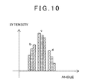
- FIG. 10 is a graph showing a light intensity distribution of a light spot interpolated based on an original image and a difference image.
- FIG. 11 is a schematic sectional elevational view of another three-dimensional laser scanner to which the target detection according to an embodiment of the present invention is applicable.
- reference numeral 1 represents a three-dimensional measuring device, e.g. a three-dimensional laser scanner.
- a target 4 is installed via a required support member such as a pole or a tripod (in this figure, a pole 5 is shown). A position where the pole 5 is installed and a height of the target 4 are known, and the three-dimensional position of the target 4 is known.
- the target 4 is retroreflective, and for example, a corner cube or a reflective sheeting can be employed.
- the three-dimensional laser scanner 1 is installed via a tripod 2 . Also, the three-dimensional laser scanner 1 is horizontally rotatable and has a scanning mirror 7 which rotates in a vertical plane via a vertical rotary shaft and is configured to irradiate a distance measuring light 8 via the scanning mirror 7 . Through cooperative operation of the horizontal rotation of the three-dimensional laser scanner 1 and the vertical rotation of the scanning mirror 7 , the distance measuring light 8 can be scanned all over the measurement range 3 . Further, by scanning the distance measuring light 8 , a three-dimensional point cloud data in the measurement range 3 can be acquired. Further, by fixing the scanning mirror 7 toward the target 4 and projecting the distance measuring light 8 to a point, a three-dimensional position of the target 4 can be measured.
- the three-dimensional laser scanner 1 has a leveling unit 9 as attached to the tripod 2 , a base member 11 as disposed on the leveling unit 9 , a frame unit 13 as disposed on the base member 11 horizontally rotatably via a horizontal rotary unit 12 , and the scanning mirror 7 disposed at the frame unit 13 vertically (vertical direction) rotatably around a vertical rotation shaft 14 .
- the leveling unit 9 has, for example, three adjusting screws 15 . By adjusting the adjusting screws 15 so that an inclination sensor (not shown) disposed on the frame unit 13 detects a horizontal position, the leveling unit 9 can be leveled.
- the horizontal rotary unit 12 has a horizontal rotation shaft 16 which is supported rotatably and vertically by the base member 11 via a bearing 10 .
- the frame unit 13 is supported by the horizontal rotation shaft 16 , and the frame unit 13 rotates together with the horizontal rotation shaft 16 .
- a horizontal driving unit 18 including a horizontal drive motor 17 and a horizontal angle detector (e.g. an encoder) 19 for detecting a rotation angle of the horizontal rotation shaft 16 are accommodated.
- the horizontal drive motor 17 By the horizontal drive motor 17 , the frame unit 13 is rotated around the horizontal rotation shaft 16 , and a rotation angle of the horizontal rotation shaft 16 with respect to the base member 11 , i.e. the rotation angle of the frame unit 13 can be detected by the horizontal angle detector 19 .
- a detection result (horizontal angle) of the horizontal angle detector 19 is input to a control arithmetic unit 31 (to be described later), and based on the detection result, a driving of the horizontal drive motor 17 is controlled by the control arithmetic unit 31 .
- a recess 21 is formed at the center, and spaces are formed at the right and left sides of the recess 21 .
- a vertical driving unit 22 and a vertical angle detector 23 are accommodated in one space (the left space in the figure).
- a distance measuring light emitter 25 In the other space (the right space in the figure), a distance measuring light emitter 25 , a common optical path unit 26 , a distance measuring unit 27 , an illumination light emitter 28 , an image pickup unit 29 and so on are accommodated, and in required positions inside the frame unit 13 , the control arithmetic unit 31 and so on are accommodated.
- a display unit 32 and an operation unit 33 are disposed in required positions of the frame unit 13 .
- the vertical rotation shaft 14 is rotatably supported by the frame unit 13 via a bearing 34 .
- One end of the vertical rotation shaft 14 projects into the recess 21 , and at the projecting end of the vertical rotation shaft 14 , the scanning mirror 7 is disposed at an angle of 45 degrees with respect to the shaft center of the vertical rotation shaft 14 .
- the scanning mirror 7 is supported by the vertical rotation shaft 14 inside the recess 21 and rotates vertically around the vertical rotation shaft 14 .
- the vertical driving unit 22 has a vertical drive motor 35 . It is so designed that the vertical rotation shaft 14 is rotated by the vertical drive motor 35 , and the scanning mirror 7 is rotated by the vertical drive motor 35 via the vertical rotation shaft 14 . It is noted that the vertical rotation shaft 14 , the scanning mirror 7 , the vertical drive motor 35 and so on constitute a scanning unit 36 .
- the vertical rotation shaft 14 is provided with the vertical angle detector 23 , e.g. an encoder, and a rotation angle of the vertical rotation shaft 14 with respected to the frame unit 13 is detected by the vertical angle detector 23 . It is so designed that a detection result (vertical angle) is input to the control arithmetic unit 31 , and a drive of the vertical drive motor 35 is controlled by the control arithmetic unit 31 based on the detection result.
- a detection result vertical angle
- a drive of the vertical drive motor 35 is controlled by the control arithmetic unit 31 based on the detection result.
- the distance measuring light emitter 25 has a distance measuring light source unit 37 , an optical path splitting member 38 such as a half mirror or a beam splitter, a light projecting optical unit 39 comprising an object lens and so on, and a mirror 41 .
- the distance measuring light source unit 37 is, for example, a semiconductor laser and emits a pulsed laser beam of an invisible infrared light as the distance measuring light 8 on a distance measuring optical axis 42 . It is so designed that the distance measuring light source unit 37 is controlled by the control arithmetic unit 31 so that the pulsed laser beam is emitted under required conditions, e.g. at a required light intensity and at a required pulse interval and so on.
- a part of the distance measuring light 8 emitted from the distance measuring light source unit 37 passes through the optical path splitting member 38 and enters the mirror 41 via the light projecting optical unit 39 and is reflected from the mirror 41 and is led to the common optical path unit 26 . Meanwhile, the rest of the distance measuring light 8 is reflected from the optical path splitting member 38 as an internal reference light and is led to the distance measuring unit 27 via an internal reference optical path 43 which will be described below.
- the common optical path unit 26 has a first beam splitter 44 and a second beam splitter 45 .
- the distance measuring light 8 reflected from the mirror 41 is reflected from the first beam splitter 44 and the second beam splitter 45 in order and after reflecting by the second beam splitter 45 , is led to the scanning mirror 7 . Meanwhile, the distance measuring light 8 passing through the first beam splitter and the second beam splitter 45 is absorbed by an antireflective member not shown in the figure.
- the scanning mirror 7 is a deflecting optical element, and it is so designed that the scanning mirror 7 deflects the horizontally entering distance measuring light 8 at a right angle, and horizontally deflects a reflected distance measuring light entering the scanning mirror 7 toward the second beam splitter 45 .
- the distance measuring light 8 led to the scanning mirror 7 from the common optical path unit 26 is reflected by the scanning mirror 7 and projected on an objected to be measured (not shown in the figure). Further, as the scanning mirror 7 is rotated around the vertical rotation shaft 14 , the distance measuring light 8 is projected in rotary irradiation in a vertical plane. Furthermore, as the horizontal rotary unit 12 rotates the frame unit 13 horizontally, the distance measuring light 8 is horizontally rotationally irradiated around the horizontal rotation shaft 16 . Therefore, through cooperative operation of the vertical rotation of the scanning mirror 7 and the horizontal rotation of the frame unit 13 , the distance measuring light 8 can scan the measurement range 3 all over.
- a reflected distance measuring light reflected from the object to be measured which exists in the measurement range 3 , enters the scanning mirror 7 and is reflected from the scanning mirror 7 and enters the common optical path unit 26 .
- the reflected distance measuring light is reflected by the second beam splitter 45 and then passes through the first beam splitter 44 and is led to the distance measuring unit 27 .
- the distance measuring unit 27 has a light receiving optical unit 46 comprising a condensing lens and so on, an optical path extension 47 , an optical path coupler 48 and a light receiving element 49 . It is so designed that the reflected distance measuring light passing through the first beam splitter 44 is led to the light receiving element 49 and also the internal reference light led through the internal reference optical path 43 is led to the light receiving element 49 via the optical path coupler 48 .
- the reflected distance measuring light passing through the first beam splitter 44 enters the light receiving optical unit 46 and is condensed by the light receiving optical unit 46 and enters the optical path extension 47 .
- the reflected distance measuring light having passed through the optical path extension 47 is received by the light receiving element 49 via the optical path coupler 48 .
- a internal reference light having passed through the internal reference optical path 43 is received by the light receiving element 49 via the optical path coupler 48 .
- the reflected distance measuring light and the internal reference light are converted into a reflected distance measuring light electric signal and an internal reference light electric signal and are sent to the control arithmetic unit 31 , and it is so designed that a distance to the object to be measured is determined based on a difference in time interval between the reflected distance measuring light electric signal and the internal reference light electric signal.
- the coordinate value of the object to be measured is calculated.
- the point cloud data for all over the measurement range 3 or the object to be measured can be acquired.
- the horizontal angle detector 19 and the vertical angle detector 23 constitute an angle detector which detects a direction of the distance measuring optical axis 42 .
- the illumination light emitter 28 has an illumination light source unit 51 and a third beam splitter 52 disposed on the optical axis of the illumination light source unit 51 . It is so designed that illumination light 53 emitted from the illumination light source unit 51 is deflected by the third beam splitter 52 and projected along an image pickup optical axis at a predetermined divergence.
- the illumination light source unit 51 is designed to emit a white light, or emit monochromatic lights of a plurality of wavelengths. In a case where the monochromatic lights of a plurality of wavelengths are emitted, it may be configured such that a plurality of laser diodes or LEDs for emitting monochromatic lights of different wavelengths are provided and the individual laser diodes or LEDs illuminate separately or simultaneously. Further, the illumination light source unit 51 may be configured to emit a white light or at least one monochromatic light separately.
- the third beam splitter 52 and an image pickup element 54 are disposed, and it is so designed that the image pickup optical axis passing through the third beam splitter 52 coincides with the optical axis of the illumination light source unit 51 .
- the image pickup element 54 outputs digital image signals and is, for example, a CCD or CMOS sensor and the like composed of an assembly of picture elements (pixels), and a position of each pixel in the image pickup element 54 can be specified.
- the illumination light 53 with a predetermined divergence is emitted. It is so designed that as the illumination light 53 passes through the second beam splitter 45 , an optical axis of the illumination light 53 is aligned with the distance measuring optical axis 42 .
- the illumination light 53 is reflected by the scanning mirror 7 , so the illumination light 53 is projected on the distance measuring optical axis 42 and is projected over an image pickup area of the image pickup unit 29 .
- an illumination light 53 reflected from the image pickup area enters the scanning mirror 7 , and the reflected illumination light reflected by the scanning mirror 7 passes through the second beam splitter 45 and the third beam splitter 52 , and is received by the image pickup element 54 . It is so designed that a two-dimensional image can be acquired based on the image signal output from the image pickup element 54 .
- the illumination light 53 may be irradiated all over the image pickup area or a part of the image pickup area.
- the operation unit 33 , the vertical angle detector 23 , and the horizontal angle detector 19 are electrically connected to the control arithmetic unit 31 , and angle detection signals from the vertical angle detector 23 and the horizontal angle detector 19 are input and by the operator's operation, signals from the control panel 33 is input to the control arithmetic unit 31 .
- the operator can set, from the operation unit 33 , a condition required to start the measurement by the three-dimensional laser scanner 1 , for example, set a measurement range, set a density of the point cloud data, or set an image pickup condition upon acquiring an image, and can enter a measurement start instruction or the like, and from the display unit 32 , these conditions and instructions can be confirmed.
- the operation unit 33 or the display unit 32 may be provided in the frame unit 13 or may be provided separately and independently and may permit a remote control through a signal transfer medium such as a radio or an infrared light and so on.
- the control arithmetic unit 31 drives the distance measuring light source unit 37 , the horizontal drive motor 17 , the vertical drive motor 35 and the illumination light source unit 51 and also drives the display unit 32 which displays a status of the operation, a measurement result or the like. Further, the control arithmetic unit 31 is provided with an external storage device 56 such as a memory card or a HDD and so on. The external storage device 56 may be provided to the control arithmetic unit 31 fixedly or detachably.
- control arithmetic unit 31 Next, description will be given on general features of the control arithmetic unit 31 .
- the control arithmetic unit 31 comprises an arithmetic unit 57 , typically represented by CPU, a storage unit 58 , a distance measuring light emission driving unit 59 for controlling a light emission at the distance measuring light source unit 37 , an illumination light emission driving unit 60 for controlling a light emitting of the illumination light source unit 51 , the horizontal driving unit 18 for controlling a driving of the horizontal drive motor 17 , the vertical driving unit 22 for controlling a driving of the vertical drive motor 35 , a distance data processing unit 61 for processing a distance data acquired by the distance measuring unit 27 , an image data processing unit 62 for processing a image data acquired by the image pickup unit 29 and so on.
- a distance measuring light emission driving unit 59 for controlling a light emission at the distance measuring light source unit 37
- an illumination light emission driving unit 60 for controlling a light emitting of the illumination light source unit 51
- the horizontal driving unit 18 for controlling a driving of the horizontal drive motor 17
- the vertical driving unit 22 for controlling a driving of the vertical drive motor 35
- the storage unit 58 stores programs such as a sequence program for performing a distance measurement, a measurement of a vertical angle, and a measurement of a horizontal angle, an arithmetic program for performing calculations such as a calculation for a distance measurement, a measurement data processing program for performing a processing of the measurement data, an image pickup program for controlling image pickup conditions of the image pickup unit 29 , an image processing program for performing a image processing, a target detecting program for detecting a target from a processed image, and programs such as an image displaying program for displaying the data on the display unit 32 , or a program for an integrated management of these programs, and further stores data such as a measurement data or a image data.
- programs such as a sequence program for performing a distance measurement, a measurement of a vertical angle, and a measurement of a horizontal angle, an arithmetic program for performing calculations such as a calculation for a distance measurement, a measurement data processing program for performing a processing of the measurement data, an image pickup program for controlling image pickup conditions of the
- functions of the distance data processing unit 61 and the image data processing unit 62 may be performed by the arithmetic unit 57 , and in this case, the distance data processing unit 61 and the image data processing unit 62 can be omitted. Further, by individually providing the distance data processing unit 61 and the image data processing unit 62 , a measurement of distance data and a measurement of image data may be performed simultaneously. In this case, a high-speed processing can be performed.
- the distance data processing unit 61 and the image data processing unit 62 may be provided separately.
- a PC may be provided separately, and functions of the distance data processing unit 61 and the image data processing unit 62 may be performed by this PC.
- communication means may be provided in the three-dimensional laser scanner 1 and the PC respectively, and the distance data and the image data may be transmitted to the PC from the three-dimensional laser scanner 1 , and a processing of the distance data and a processing of the image data may be performed by the PC.
- a required communication means such as an optical communication, a radio communication or a LAN may be employed.
- an installation position of the three-dimensional laser scanner 1 has to be known. Therefore, in a case where the installation position of the three-dimensional laser scanner 1 is unknown, as a lead-up to the measurement, it is necessary to obtain the position of the three-dimensional laser scanner 1 .
- the illumination light source unit 51 emits a plurality of laser beams of different wavelengths and/or a white light as the illumination light 53 .
- the three-dimensional laser scanner 1 is installed at an arbitrary position, and the adjusting screws 15 are turned so that the inclination sensor (not shown) disposed on the frame unit 13 detects a horizontal position and the three-dimensional laser scanner 1 is leveled so as to have a horizontal position. Further, under the condition that the three-dimensional laser scanner 1 is leveled, the distance measuring optical axis 42 becomes horizontal at a reference position of the scanning mirror 7 .
- the position of the three-dimensional laser scanner 1 is unknown, and the target 4 such as a corner cube is installed at a known position via the pole 5 .
- the image pickup element 54 a color CCD or an image sensor and so on may be employed.
- the operator directs the three-dimensional laser scanner 1 toward the target 4 and starts a detection processing of the target 4 .
- the scanning mirror 7 remains standstill in the reference position.
- the illumination light source unit 51 is driven with the illumination light emission driving unit 60 .
- the white illumination light 53 is projected toward an image pickup area via the scanning mirror 7 , and an image, to which the white illumination light 53 (first illuminated image) is irradiated, is acquired by the image pickup unit 29 , and the first illuminated image is stored in the storage unit 58 .
- the illumination light source unit 51 is stopped by the illumination light emission driving unit 60 , and an image, to which the white illumination light 53 (unilluminated image) is not irradiated, is acquired by the image pickup unit 29 , and the unilluminated image is stored in the storage unit 58 .
- both the first illuminated image and the unilluminated image are an normal original image 64 in which the background is imaged together with the target 4 , as shown in FIG. 4A .
- the original image 64 a retroreflected light from the target 4 appears as a light spot 65 .
- the unilluminated image is subtracted from the first illuminated image.
- the background is removed from the original image 64 .
- a retroreflective object other than the target 4 may also exist in the original image 64 , and a plurality of light spots may exist in the first difference image 66 .
- the image pickup element 54 is composed of a light receiving element sensitive to a blue, a green and a red
- a hue of each light spot detected in the first difference image 66 can be judged according to the ratio of these colors, and the light spot 65 corresponding to the target 4 can be detected.
- the target 4 a property of selectively reflecting a predetermined wavelength, i.e. the target 4 has a predetermined color
- the light spot 65 corresponding to the target 4 can be detected among candidates based on a judged result for the hue.
- the first illuminated image is acquired according to the white illumination light 53 , and the candidates for the target 4 are detected based on the first illuminated image and the unilluminated image, and the target 4 is detected among the candidates based on the hue.
- the illumination light 53 may be replaced by a plurality of types of monochromatic lights, e.g. two types of monochromatic lights, and two types of illuminated images may be acquired for each color with this illumination light 53 , and based on the two types of illuminated images and the unilluminated image, the target may be detected.
- two types of illuminated images may be acquired by irradiating two types of monochromatic lights simultaneously and separating and extracting green components and red components out of signals from the light receiving element.
- a monochromatic light with a predetermined wavelength e.g. a pure green illumination light 53
- an image as irradiated by the pure green illumination light 53 (second illuminated image) is acquired.
- a monochromatic light of a color different from the pure green e.g. a pure red illumination light 53
- an image as irradiated by the pure red illumination light 53 (third illuminated image) is acquired, and the unilluminated image is further acquired.
- the second illuminated image and the unilluminated image are compared and subtracted and a second difference image is calculated, and also the third illuminated image and the unilluminated image are compared and subtracted and a third difference image is calculated.
- the target 4 has an optical property of selectively reflecting a pure green light or if the target 4 is made of a green reflective sheeting and selectively reflects a pure green light, only the green component of the illumination light 53 is reflected by the target 4 , and the light other than the green is reflected in an attenuated manner.
- the illumination light 53 is a pure green light and the second difference image is calculated from the second illuminated image and the unilluminated image, a retroreflected light from the target 4 appears as the light spot 65 in the second difference image without any attenuation.
- the monochromatic light for acquiring the third illuminated image is a pure red light which is complementary to a pure green light
- the pure red light is irradiated, almost no reflection comes from the target 4 , and the light spot 65 does not appear in the third difference image. Further, a reflected light from an object or a part having a red component is received in an attenuated state.
- the second difference image and the third difference image are compared with each other by the image data processing unit 62 .
- the hue can be judged by obtaining a ratio of light quantities and an intensity for the detected candidates for the target 4 .
- the target 4 can be detected based on the judged hue.
- the pure green light is irradiated, the pure green light is reflected by the target 4 without much attenuation. Ina case where the pure red light is irradiated, there is no reflected light from the target 4 .
- the light spot 65 in the second difference image can be discriminated as the target 4 , so that the light spot 65 can be detected reliably without the need to determine the hue.
- the image pickup element 54 may be a monochrome photodetection sensor only sensitive to the brightness.
- the configurations described above may be combined, and the target 4 may be detected from a white light illuminated image for which a white light is employed as the illumination light 53 , a monochromatic light illuminated image for which at least one monochromatic light, e.g. a pure red light is employed as the illumination light 53 , and the unilluminated image.
- a white light illuminated difference image is calculated. From the white light illuminated difference image, candidates for the target 4 are detected, and the target 4 is detected based on a hue. Further, a monochromatic light illuminated difference image is calculated based on the monochromatic light illuminated image and the unilluminated image. In a case where the pure red light is irradiated, a sunlight having passed through waving branches and leaves or a sunlight reflected from a surface of a river can be detected as a white background light.
- the reflected light and the background light can be discriminated from each other, so it is possible to improve a detection accuracy of the target 4 which is retroreflective and colorless or has a given hue.
- a pattern is formed by the reflective sheeting, if a first pattern area capable of reflecting a monochromatic light of a certain wavelength and a second pattern area capable of reflecting another monochromatic light complementary to the monochromatic light are formed, different patterns can be obtained by switching the illumination light 53 , so it becomes easier to detect the target 4 .
- the target 4 has a property of selectively reflecting a wavelength and a white light is employed as the illumination light 53 and a plurality of wavelength selective filters having different transmission properties (e.g. a green light transmission filter and a red light transmission filter) are allowed to be individually detachably inserted into a light receiving optical path of the image pickup unit 29 and an entering reflected light is received for every wavelength through the wavelength selective filters, whereby the same effects can be obtained.
- a plurality of wavelength selective filters having different transmission properties e.g. a green light transmission filter and a red light transmission filter
- FIG. 5A and FIG. 5B are enlarged views of an essential portion showing one example of the illumination light emitter 28 and the image pickup unit 29 in the present embodiment.
- the third beam splitter 52 is provided to align the optical axis of the illumination light source unit 51 with the image pickup optical axis of the image pickup unit 29 .
- the image pickup unit 29 is disposed on the reflecting optical axis of the third beam splitter 52 and the only one illumination light source unit 51 is disposed on a transmitting optical axis of the third beam splitter 52 .
- This arrangement is the same as described in the embodiment described above. It is noted that in the figures, 68 represents a light emitting source.
- the image pickup unit 29 is configured by an image pickup lens 69 and the image pickup element 54 .
- the illumination light source unit 51 is configured by an illumination lens 70 and the light emitting source 68 .
- the light spot 65 is detected as a single spot from the first difference image 66 . Accordingly, in a case where the distance measuring optical axis 42 is aligned with a center of the target 4 , a position of a peak intensity of the light spot 65 is obtained on the image pickup element 54 , and the vertical drive motor 35 and the horizontal drive motor 17 are controlled by the vertical driving unit 22 and the horizontal driving unit 18 so that the position of the peak intensity coincides with a reference position, e.g. a center on the image pickup element 54 . Whereby the distance measuring optical axis 42 can be aligned with the center of the target 4 .
- FIG. 6A and FIG. 6B show another embodiment of the illumination light source unit 51 .
- two illumination light source units 51 a , 51 b are disposed point-symmetrically with respect to a center of an optical axis of the image pickup unit 29 .
- Optical axes of the illumination light source units 51 a , 51 b are parallel to the optical axis of the image pickup unit 29 (i.e. the distance measuring optical axis 42 ).
- two light spots 65 , 65 can be detected in a difference image.
- a midpoint between peak intensities of the two light spots 65 , 65 indicates a center of the target 4 . Accordingly, by controlling the vertical drive motor 35 and the horizontal drive motor 17 by the vertical driving unit 22 and the horizontal driving unit 18 so that the midpoint between the peak intensities of the two light spots 65 , 65 coincides with a reference position on the image pickup element 54 , the distance measuring optical axis 42 can be aligned with the center of the target 4 .
- a single light spot 65 is detected in the difference image.
- the vertical drive motor 35 and the horizontal drive motor 17 are controlled by the vertical driving unit 22 and the horizontal driving unit 18 so that a position of a peak intensity of the light spot 65 coincides with the reference position on the image pickup element 54 .
- the distance measuring optical axis 42 can be aligned with the center of the target 4 .
- a size of a light spot with respect to pixels 67 of the image pickup element 54 may become as small as about three pixels, and there may be a case where it is impossible to acquire a sufficient data to determine a peak position of the light spot 65 .
- FIG. 7 to FIG. 9 are drawings focusing on a partial element 54 ′ (five rows (a-e) of pixels ⁇ five columns (1-5) of pixels) of the image pickup element 54 . Also, in FIG. 7A , FIG. 8A , and FIG. 9A , the circle shown by a dotted line is the light spot 65 . Difference images that can be acquired by the partial element 54 ′ are referred as difference images 66 a to 66 c.
- a horizontal light intensity distribution of a light spot 65 as received by the pixels is expressed as a bar chart, as shown in FIG. 7B . Since the light spot 65 is as small as about three pixels, only three data can be acquired.
- the vertical drive motor 35 and the horizontal drive motor 17 are driven by the vertical driving unit 22 and the horizontal driving unit 18 , and an image pickup direction is horizontally changed by an angle smaller than an angle corresponding to one pixel of the image pickup element 54 (e.g.
- the difference images 66 b , 66 c can be acquired, and also with respect to the difference images 66 b , 66 c , as shown in FIG. 8B and FIG. 9B , it is possible to individually obtain the horizontal light intensity distribution of the light spot 65 consisting of three data.
- a horizontal light intensity distribution of the light spot 65 consisting of nine data can be obtained, so the horizontal peak position of the light spot 65 can be detected with high accuracy.
- the image pickup direction is vertically changed by an angle smaller than the angle corresponding to one pixel pitch of the image pickup element 54 and images are taken, and a plurality of difference images is acquired. Then, by arranging the light intensity distribution obtained from the previously taken images and a light intensity distributions obtained from difference images associated with the image pickup angle, a data for determining the peak position of the light spot 65 can be interpolated, so the vertical peak position of the light spot 65 can be detected with high accuracy.
- the data is interpolated and based on the horizontal and vertical peak positions of the light spot 65 , the vertical drive motor 35 and the horizontal drive motor 17 are controlled by the vertical driving unit 22 and the horizontal driving unit 18 , whereby the distance measuring optical axis 42 can be aligned with the center of the target 4 .
- the difference image may be acquired by changing the image pickup direction diagonally.
- the horizontal and vertical light intensity distributions of the light spot 65 can be obtained simultaneously, so the horizontal and vertical data can be interpolated at once.
- a general position may be obtained from the image pickup element 54 , and a scanning area may be set as a center at the general position. The scanning is performed over the scanning area by the distance measuring light 8 , a central position of the target 4 is determined based on a distribution result of a reflection intensity. Thus, the distance measuring optical axis 42 may be aligned with the center of the target 4 .
- a distance to the target 4 is measured with the three-dimensional laser scanner 1 .
- the distance measuring light source unit 37 is driven by the distance measuring light emission driving unit 59 , and with the distance measuring optical axis 42 kept in alignment with the center of the target 4 , a pulsed laser beam is emitted from the distance measuring light source unit 37 as the distance measuring light 8 .
- a part of the distance measuring light 8 is split by the optical path splitting member 38 toward the internal reference optical path 43 .
- the rest of the distance measuring light 8 is collimated into parallel luminous fluxes through the light projecting optical unit 39 .
- the distance measuring light 8 is deflected at a right angle by the scanning mirror 7 and is projected toward the center of the target 4 .
- a reflected distance measuring light reflected from the target 4 enters the scanning mirror 7 , and is deflected at a right angle by the scanning mirror 7 , and is reflected by the second beam splitter 45 , and passes through the first beam splitter 44 . Then, the reflected distance measuring light is condensed by the light receiving optical unit 46 . The reflected distance measuring light condensed by the light receiving optical unit 46 passes through the optical path extension 47 and enters the light receiving element 49 via the optical path coupler 48 . Meanwhile, the distance measuring light 8 split by optical path splitting member 38 (internal reference light) also enters the light receiving element 49 via the internal reference optical path 43 and the optical path coupler 48 .
- the distance measuring light 8 and the reflected distance measuring light are converted into a distance measuring light electric signal and a reflected distance measuring light electric signal and sent to the control arithmetic unit 31 .
- a time interval between the distance measuring light electric signal and the reflected distance measuring light electric signal is determined by the distance data processing unit 61 , and a distance to the target 4 is calculated based on the determined time interval.
- the calculated distance to the target 4 is stored in the storage unit 58 .
- a position of the three-dimensional laser scanner 1 with respect to the target 4 can be determined, so the position of the three-dimensional laser scanner 1 can become known.
- an operation of taking images is performed by the three-dimensional laser scanner 1 directed toward the target 4 and the target 4 is detected by a simple image processing, and a measurement point of the target 4 is aligned with a distance measuring optical axis 42 , as a result, it is not necessary to scan a distance measuring light for detecting the target 4 or to scan the distance measuring light over a wide range, and a processing time can be shortened and an efficiency of an operation can be improved.
- a hue of the target 4 can be judged, so a light spot reflected from a reflecting plate of a traffic sign, a car or the like and a light spot reflected from the target 4 can be distinguished from each other, and a false detection of the target 4 can be avoided.
- the target 4 is detected from a difference image based on an illuminated image acquired under a condition where the monochromatic illumination light 53 is irradiated from the illumination light source unit 51 and based on an unilluminated image acquired under a condition where the illumination light 53 is not irradiated from the illumination light source unit 51 , however, another configuration may be adopted as long as the target 4 can be detected.
- the illumination light source unit 51 is replaced by a light source which irradiates a near-infrared light as the illumination light 53
- the image pickup unit 29 is provided with a wavelength selector which freely selects and transmits a wavelength of a light entering the image pickup element 54 .
- the wavelength selector is, for example, a filter capable of switching between a portion which transmits a visible light and a portion which transmits a near-infrared light, and when a panoramic image or a moving image is to be acquired, the portion which transmits a visible light is used, and when the target 4 such as a retroreflective corner cube is to be detected, the portion which transmits only a near-infrared light is used, so that a background light in an acquired image can be reduced.
- a detection of the target 4 in the present embodiment is applicable not only to the three-dimensional laser scanner 1 but also to a three-dimensional laser scanner 71 shown in FIG. 11 .
- the three-dimensional laser scanner 71 is composed mainly of a measuring device main unit 73 accommodating a leveling unit 9 , a rotary mechanism 72 , a distance measuring unit 27 , an image pickup unit 29 , a control arithmetic unit 31 and so on.
- a rotary base 74 is mounted rotatably on an upper portion of the measuring device main unit 73
- a rotary projecting unit 75 is mounted on the upper portion of the rotary base 74 .
- the rotary projecting unit 75 has a mirror holder (not shown) attached to the rotary base 74 and a scanning mirror 7 rotatably mounted on the mirror holder.
- the scanning mirror 7 is designed to rotate vertically around a horizontal shaft by a vertical rotary motor (not shown) and also rotate horizontally by a horizontal rotary motor 76 of the rotary mechanism 72 , together with the rotary base 74 .
- a distance measuring light 8 projected from the distance measuring unit 27 is led to the scanning mirror 7 and reflected by the scanning mirror 7 toward an object to be measured. Further, a reflected distance measuring light reflected from the object to be measured is reflected from the scanning mirror 7 and is partially led to the image pickup unit 29 , and an image can be acquired, and also the rest is led to the distance measuring unit 27 , and a distance to the object to be measured is measured.
- the distance measuring light 8 can be scanned over total circumference within a predetermined vertical range. Further, by scanning the distance measuring light 8 , a three-dimensional point cloud data of the object to be measured can be acquired. Further, by fixing the scanning mirror 7 toward the target 4 (see FIG. 1 ) and projecting the distance measuring light 8 to a point, a three-dimensional position of the target 4 can be measured.
Landscapes
- Physics & Mathematics (AREA)
- General Physics & Mathematics (AREA)
- Engineering & Computer Science (AREA)
- Radar, Positioning & Navigation (AREA)
- Remote Sensing (AREA)
- Length Measuring Devices By Optical Means (AREA)
- Measurement Of Optical Distance (AREA)
Applications Claiming Priority (2)
| Application Number | Priority Date | Filing Date | Title |
|---|---|---|---|
| JP2012-231949 | 2012-10-19 | ||
| JP2012231949A JP6120521B2 (ja) | 2012-10-19 | 2012-10-19 | 3次元測量装置及び3次元測量システム |
Publications (2)
| Publication Number | Publication Date |
|---|---|
| US20140111618A1 US20140111618A1 (en) | 2014-04-24 |
| US9243897B2 true US9243897B2 (en) | 2016-01-26 |
Family
ID=49328464
Family Applications (1)
| Application Number | Title | Priority Date | Filing Date |
|---|---|---|---|
| US14/050,414 Active 2034-08-13 US9243897B2 (en) | 2012-10-19 | 2013-10-10 | Three-dimensional measuring device and three-dimensional measuring system |
Country Status (4)
| Country | Link |
|---|---|
| US (1) | US9243897B2 (de) |
| EP (1) | EP2722645B1 (de) |
| JP (1) | JP6120521B2 (de) |
| CA (1) | CA2830297A1 (de) |
Cited By (2)
| Publication number | Priority date | Publication date | Assignee | Title |
|---|---|---|---|---|
| CN106989736A (zh) * | 2017-02-28 | 2017-07-28 | 苏州迪美格智能科技有限公司 | 一种基于结构光阵列的空间测绘系统及方法 |
| US10983214B2 (en) * | 2016-09-15 | 2021-04-20 | Zoller & Fröhlich GmbH | Laser scanner comprising a removeable internal memory controlling function of the scanner |
Families Citing this family (46)
| Publication number | Priority date | Publication date | Assignee | Title |
|---|---|---|---|---|
| DE102012223929A1 (de) * | 2012-12-20 | 2014-06-26 | Hilti Aktiengesellschaft | Verfahren und Vorrichtung zum Bestimmen der zweidimensionalen Ortskoordinaten eines Zielobjektes |
| CN104075670B (zh) * | 2014-07-10 | 2017-02-15 | 苏州金螳螂建筑装饰股份有限公司 | 红外线半径测量仪及其半径测量和圆弧定位方法 |
| KR20160078023A (ko) * | 2014-12-24 | 2016-07-04 | 삼성전자주식회사 | 디스플레이 제어 장치 및 디스플레이 제어 방법 |
| JP6438311B2 (ja) | 2015-01-27 | 2018-12-12 | 株式会社トプコン | 測量システム、測量方法、測量機及び測量用反射ターゲット |
| JP6498513B2 (ja) * | 2015-04-30 | 2019-04-10 | 株式会社トプコン | 3次元測量装置及び3次元測量方法 |
| JP6498528B2 (ja) * | 2015-05-28 | 2019-04-10 | 株式会社トプコン | 測量装置 |
| JP6557516B2 (ja) * | 2015-06-04 | 2019-08-07 | 株式会社トプコン | 3次元測量装置及び3次元測量方法 |
| GB2542762B (en) * | 2015-09-21 | 2018-11-21 | Imetrum Ltd | Measuring device and method |
| JP2017072466A (ja) | 2015-10-07 | 2017-04-13 | 株式会社トプコン | 光波距離測定装置 |
| JP6653051B2 (ja) * | 2016-02-29 | 2020-02-26 | クモノスコーポレーション株式会社 | 光走査装置 |
| JP6682730B2 (ja) * | 2016-02-29 | 2020-04-15 | クモノスコーポレーション株式会社 | 光走査装置 |
| US11255663B2 (en) | 2016-03-04 | 2022-02-22 | May Patents Ltd. | Method and apparatus for cooperative usage of multiple distance meters |
| CN107607056B (zh) * | 2016-07-12 | 2024-08-09 | 吕方达 | 激光形貌检测器 |
| JP7012485B2 (ja) * | 2016-12-27 | 2022-01-28 | 株式会社ワコム | 画像情報処理装置および画像情報処理方法 |
| KR102235227B1 (ko) * | 2017-02-17 | 2021-04-02 | 호쿠요덴키 가부시키가이샤 | 물체 포착 장치, 포착 대상물, 및 물체 포착 시스템 |
| KR101832364B1 (ko) * | 2017-02-22 | 2018-04-04 | 경희대학교 산학협력단 | 재귀 반사 필름을 이용한 거리 측정 장치 및 방법 |
| JP6943528B2 (ja) | 2017-04-05 | 2021-10-06 | 株式会社トプコン | レーザスキャナ |
| CN107024174A (zh) * | 2017-05-18 | 2017-08-08 | 北京市建筑工程研究院有限责任公司 | 基于三维激光扫描技术的粉状堆料体积测量装置及方法 |
| JP2019015697A (ja) * | 2017-07-11 | 2019-01-31 | ソニーセミコンダクタソリューションズ株式会社 | 距離測定装置及び移動体装置 |
| JP6959068B2 (ja) * | 2017-08-22 | 2021-11-02 | 株式会社トプコン | 転がり軸受への予圧付与構造および三次元測量装置 |
| JP7084705B2 (ja) * | 2017-09-13 | 2022-06-15 | 株式会社トプコン | 測量装置 |
| KR101920012B1 (ko) | 2017-09-29 | 2018-11-19 | 경희대학교 산학협력단 | 재귀 반사 필름을 이용한 거리 측정 장치 및 방법 |
| JP6709553B2 (ja) * | 2018-01-30 | 2020-06-17 | クモノスコーポレーション株式会社 | 三次元レーザー光走査装置 |
| CN108632492A (zh) * | 2018-05-16 | 2018-10-09 | 天津微深通用科技有限公司 | 一种用于三维扫描的可调节多角度支架 |
| JP6813541B2 (ja) | 2018-07-26 | 2021-01-13 | ファナック株式会社 | 光学系異常を検出する測距装置 |
| JP7118845B2 (ja) | 2018-10-04 | 2022-08-16 | 株式会社トプコン | 角度検出システム |
| EP3640678B1 (de) * | 2018-10-17 | 2022-11-09 | Trimble Jena GmbH | Verfolger, vermessungsvorrichtung und verfahren zur verfolgung eines ziels |
| EP3640677B1 (de) | 2018-10-17 | 2023-08-02 | Trimble Jena GmbH | Verfolger einer vermessungsvorrichtung zur verfolgung eines ziels |
| EP3640590B1 (de) | 2018-10-17 | 2021-12-01 | Trimble Jena GmbH | Vermessungsvorrichtung zur vermessung eines objekts |
| CN109764802B (zh) * | 2018-12-04 | 2020-12-08 | 上海艾亚建筑设计咨询有限公司 | 基于无线感应信号构建虚拟空间模型的系统及方法 |
| CN109682360B (zh) * | 2019-02-01 | 2024-07-26 | 中国铁建重工集团股份有限公司 | 具有三维扫描功能的工程车和扫描处理方法 |
| EP3696498A1 (de) | 2019-02-15 | 2020-08-19 | Trimble Jena GmbH | Vermessungsinstrument und verfahren zur kalibrierung eines vermessungsinstruments |
| JP7539060B2 (ja) * | 2019-03-25 | 2024-08-23 | 北陽電機株式会社 | 物体検出システム、搬送台車及び物体検出装置 |
| CN114128417B (zh) * | 2019-07-26 | 2024-03-12 | 株式会社富士 | 对基板作业系统 |
| JP7428492B2 (ja) * | 2019-08-26 | 2024-02-06 | 株式会社ミツトヨ | 検査方法および補正方法 |
| JP7360298B2 (ja) * | 2019-10-23 | 2023-10-12 | 株式会社トプコン | 測量装置 |
| CN111811782A (zh) * | 2020-08-05 | 2020-10-23 | 长春理工大学 | 一种空间碎片测距成像复合光学系统的检测装置及方法 |
| CN112146752B (zh) * | 2020-09-28 | 2022-05-20 | 江苏省计量科学研究院(江苏省能源计量数据中心) | 用于道路交通信号灯光强分布特性测量的校准装置 |
| CN112630795B (zh) * | 2020-12-24 | 2023-05-26 | 浙江大学滨海产业技术研究院 | 一种基于2d激光雷达的三维点云数据合成系统 |
| JP7464558B2 (ja) | 2021-03-29 | 2024-04-09 | 株式会社トプコン | 測量データ処理装置、測量データ処理方法および測量データ処理用プログラム |
| CN113405490A (zh) * | 2021-06-17 | 2021-09-17 | 西安应用光学研究所 | 高分辨率二维快速控制反射镜动态角度测量装置 |
| CN113903179B (zh) * | 2021-09-30 | 2022-07-26 | 山东大学 | 一种基于点云密度叠加分布的多线束激光雷达背景滤除装置的使用方法 |
| CN115359183B (zh) * | 2022-08-16 | 2023-05-09 | 中建一局集团第五建筑有限公司 | 一种三维模型表现装置 |
| CN115657061B (zh) * | 2022-12-13 | 2023-04-07 | 成都量芯集成科技有限公司 | 一种室内墙面三维扫描装置及方法 |
| CN116299497B (zh) * | 2023-05-12 | 2023-08-11 | 深圳深浦电气有限公司 | 光学检测的方法、装置和计算机可读存储介质 |
| CN117346699B (zh) * | 2023-12-06 | 2024-02-02 | 深圳市智鼎自动化技术有限公司 | 一种激光振镜测试装置及激光振镜调试系统 |
Citations (10)
| Publication number | Priority date | Publication date | Assignee | Title |
|---|---|---|---|---|
| US6804380B1 (en) | 2000-05-18 | 2004-10-12 | Leica Geosystems Hds, Inc. | System and method for acquiring tie-point location information on a structure |
| US20060279745A1 (en) | 2005-06-13 | 2006-12-14 | Wenstrand John S | Color imaging system for locating retroreflectors |
| US20080074637A1 (en) * | 2006-09-26 | 2008-03-27 | Kabushiki Kaisha Topcon | Laser scanner |
| US20100091263A1 (en) * | 2008-10-09 | 2010-04-15 | Kabushiki Kaisha Topcon | Laser surveying system and distance measuring method |
| US20100245587A1 (en) | 2009-03-31 | 2010-09-30 | Kabushiki Kaisha Topcon | Automatic tracking method and surveying device |
| WO2011098131A1 (en) | 2010-02-11 | 2011-08-18 | Trimble Ab | Dual transmitter tracker |
| DE102010024014A1 (de) | 2010-06-16 | 2011-12-22 | Trimble Jena Gmbh | Ziel für ein geodätisches Gerät |
| US20120229870A1 (en) * | 2011-03-07 | 2012-09-13 | Kabushiki Kaisha Topcon | Panoramic Image Preparing Method And Three-Dimensional Laser Scanner |
| US20120249997A1 (en) * | 2011-03-29 | 2012-10-04 | Kabushiki Kaisha Topcon | Laser Scanner And Method For Detecting Mobile Object |
| US8294769B2 (en) | 2008-07-05 | 2012-10-23 | Kabushiki Kaisha Topcon | Surveying device and automatic tracking method |
Family Cites Families (2)
| Publication number | Priority date | Publication date | Assignee | Title |
|---|---|---|---|---|
| JPH11351870A (ja) * | 1998-06-10 | 1999-12-24 | Tokyu Constr Co Ltd | 自動位置測定装置及び方法 |
| JP3937154B2 (ja) * | 2002-06-28 | 2007-06-27 | 株式会社トプコン | 位置検出装置 |
-
2012
- 2012-10-19 JP JP2012231949A patent/JP6120521B2/ja active Active
-
2013
- 2013-10-10 US US14/050,414 patent/US9243897B2/en active Active
- 2013-10-15 EP EP13188772.1A patent/EP2722645B1/de active Active
- 2013-10-15 CA CA2830297A patent/CA2830297A1/en not_active Abandoned
Patent Citations (12)
| Publication number | Priority date | Publication date | Assignee | Title |
|---|---|---|---|---|
| US6804380B1 (en) | 2000-05-18 | 2004-10-12 | Leica Geosystems Hds, Inc. | System and method for acquiring tie-point location information on a structure |
| US20060279745A1 (en) | 2005-06-13 | 2006-12-14 | Wenstrand John S | Color imaging system for locating retroreflectors |
| US20080074637A1 (en) * | 2006-09-26 | 2008-03-27 | Kabushiki Kaisha Topcon | Laser scanner |
| US8294769B2 (en) | 2008-07-05 | 2012-10-23 | Kabushiki Kaisha Topcon | Surveying device and automatic tracking method |
| US20100091263A1 (en) * | 2008-10-09 | 2010-04-15 | Kabushiki Kaisha Topcon | Laser surveying system and distance measuring method |
| US20100245587A1 (en) | 2009-03-31 | 2010-09-30 | Kabushiki Kaisha Topcon | Automatic tracking method and surveying device |
| JP2010237169A (ja) | 2009-03-31 | 2010-10-21 | Topcon Corp | 自動追尾方法及び測量装置 |
| US8395665B2 (en) | 2009-03-31 | 2013-03-12 | Kabushiki Kaisha Topcon | Automatic tracking method and surveying device |
| WO2011098131A1 (en) | 2010-02-11 | 2011-08-18 | Trimble Ab | Dual transmitter tracker |
| DE102010024014A1 (de) | 2010-06-16 | 2011-12-22 | Trimble Jena Gmbh | Ziel für ein geodätisches Gerät |
| US20120229870A1 (en) * | 2011-03-07 | 2012-09-13 | Kabushiki Kaisha Topcon | Panoramic Image Preparing Method And Three-Dimensional Laser Scanner |
| US20120249997A1 (en) * | 2011-03-29 | 2012-10-04 | Kabushiki Kaisha Topcon | Laser Scanner And Method For Detecting Mobile Object |
Non-Patent Citations (1)
| Title |
|---|
| European communication dated Dec. 3, 2014 in corresponding European patent application No. 13188772.1. |
Cited By (2)
| Publication number | Priority date | Publication date | Assignee | Title |
|---|---|---|---|---|
| US10983214B2 (en) * | 2016-09-15 | 2021-04-20 | Zoller & Fröhlich GmbH | Laser scanner comprising a removeable internal memory controlling function of the scanner |
| CN106989736A (zh) * | 2017-02-28 | 2017-07-28 | 苏州迪美格智能科技有限公司 | 一种基于结构光阵列的空间测绘系统及方法 |
Also Published As
| Publication number | Publication date |
|---|---|
| JP6120521B2 (ja) | 2017-04-26 |
| US20140111618A1 (en) | 2014-04-24 |
| EP2722645B1 (de) | 2018-05-09 |
| JP2014085134A (ja) | 2014-05-12 |
| CA2830297A1 (en) | 2014-04-19 |
| EP2722645A3 (de) | 2014-12-31 |
| EP2722645A2 (de) | 2014-04-23 |
Similar Documents
| Publication | Publication Date | Title |
|---|---|---|
| US9243897B2 (en) | Three-dimensional measuring device and three-dimensional measuring system | |
| KR101257586B1 (ko) | 광축 조정 장치, 광축 조정 방법 및 투사형 표시 장치 | |
| US10488196B2 (en) | Laser scanner system and registration method of point cloud data | |
| US11004250B2 (en) | Point cloud data display system | |
| JP5688876B2 (ja) | レーザスキャナ測定システムの較正方法 | |
| JP5081014B2 (ja) | ターゲット及びこれを用いた三次元形状測定装置 | |
| US10634791B2 (en) | Laser scanner system and registration method of point cloud data | |
| JP2022174329A (ja) | Lidarに基づく3次元撮像のための統合された照射及び検出 | |
| US9551575B2 (en) | Laser scanner having a multi-color light source and real-time color receiver | |
| JP4228132B2 (ja) | 位置測定装置 | |
| US20100134596A1 (en) | Apparatus and method for capturing an area in 3d | |
| EP2498102B1 (de) | Panoramabildherstellungsverfahren und dreidimensionaler Laserscanner | |
| US20120069325A1 (en) | Device for optically scanning and measuring an environment | |
| JP2021076603A (ja) | 光電センサ及び物体検出方法 | |
| JPH04232580A (ja) | 3次元カラーイメージ化方法および装置 | |
| JP7118845B2 (ja) | 角度検出システム | |
| CN110082771A (zh) | 用于检测对象的光电传感器和方法 | |
| US20220120863A1 (en) | Three-dimensional scanning and image reconstruction thereof | |
| CN108253905A (zh) | 垂直彩色共焦扫描方法和系统 | |
| US20140125997A1 (en) | Device and method for calibrating the direction of a polar measurement device | |
| JP2003014430A (ja) | 3次元測定方法および3次元測定装置 | |
| KR101005782B1 (ko) | 광 스캐너 | |
| US20210080577A1 (en) | Three-dimensional survey apparatus, three-dimensional survey method, and three-dimensional survey program | |
| JP2008032951A (ja) | 光学装置 | |
| US10742881B1 (en) | Combined temporal contrast sensing and line scanning |
Legal Events
| Date | Code | Title | Description |
|---|---|---|---|
| AS | Assignment |
Owner name: KABUSHIKI KAISHA TOPCON, JAPAN Free format text: ASSIGNMENT OF ASSIGNORS INTEREST;ASSIGNORS:KUMAGAI, KAORU;INOUE, TAKAHIRO;YOSHINO, KEN-ICHIRO;REEL/FRAME:031378/0274 Effective date: 20130913 |
|
| STCF | Information on status: patent grant |
Free format text: PATENTED CASE |
|
| MAFP | Maintenance fee payment |
Free format text: PAYMENT OF MAINTENANCE FEE, 4TH YEAR, LARGE ENTITY (ORIGINAL EVENT CODE: M1551); ENTITY STATUS OF PATENT OWNER: LARGE ENTITY Year of fee payment: 4 |
|
| MAFP | Maintenance fee payment |
Free format text: PAYMENT OF MAINTENANCE FEE, 8TH YEAR, LARGE ENTITY (ORIGINAL EVENT CODE: M1552); ENTITY STATUS OF PATENT OWNER: LARGE ENTITY Year of fee payment: 8 |