US9187080B2 - Control apparatus for vehicle - Google Patents
Control apparatus for vehicle Download PDFInfo
- Publication number
- US9187080B2 US9187080B2 US14/366,547 US201214366547A US9187080B2 US 9187080 B2 US9187080 B2 US 9187080B2 US 201214366547 A US201214366547 A US 201214366547A US 9187080 B2 US9187080 B2 US 9187080B2
- Authority
- US
- United States
- Prior art keywords
- control amount
- attitude control
- attitude
- vehicle
- abnormality
- Prior art date
- Legal status (The legal status is an assumption and is not a legal conclusion. Google has not performed a legal analysis and makes no representation as to the accuracy of the status listed.)
- Active
Links
Images


Classifications
-
- B—PERFORMING OPERATIONS; TRANSPORTING
- B60—VEHICLES IN GENERAL
- B60W—CONJOINT CONTROL OF VEHICLE SUB-UNITS OF DIFFERENT TYPE OR DIFFERENT FUNCTION; CONTROL SYSTEMS SPECIALLY ADAPTED FOR HYBRID VEHICLES; ROAD VEHICLE DRIVE CONTROL SYSTEMS FOR PURPOSES NOT RELATED TO THE CONTROL OF A PARTICULAR SUB-UNIT
- B60W10/00—Conjoint control of vehicle sub-units of different type or different function
- B60W10/18—Conjoint control of vehicle sub-units of different type or different function including control of braking systems
-
- B—PERFORMING OPERATIONS; TRANSPORTING
- B60—VEHICLES IN GENERAL
- B60G—VEHICLE SUSPENSION ARRANGEMENTS
- B60G17/00—Resilient suspensions having means for adjusting the spring or vibration-damper characteristics, for regulating the distance between a supporting surface and a sprung part of vehicle or for locking suspension during use to meet varying vehicular or surface conditions, e.g. due to speed or load
- B60G17/015—Resilient suspensions having means for adjusting the spring or vibration-damper characteristics, for regulating the distance between a supporting surface and a sprung part of vehicle or for locking suspension during use to meet varying vehicular or surface conditions, e.g. due to speed or load the regulating means comprising electric or electronic elements
- B60G17/016—Resilient suspensions having means for adjusting the spring or vibration-damper characteristics, for regulating the distance between a supporting surface and a sprung part of vehicle or for locking suspension during use to meet varying vehicular or surface conditions, e.g. due to speed or load the regulating means comprising electric or electronic elements characterised by their responsiveness, when the vehicle is travelling, to specific motion, a specific condition, or driver input
-
- B—PERFORMING OPERATIONS; TRANSPORTING
- B60—VEHICLES IN GENERAL
- B60G—VEHICLE SUSPENSION ARRANGEMENTS
- B60G17/00—Resilient suspensions having means for adjusting the spring or vibration-damper characteristics, for regulating the distance between a supporting surface and a sprung part of vehicle or for locking suspension during use to meet varying vehicular or surface conditions, e.g. due to speed or load
- B60G17/015—Resilient suspensions having means for adjusting the spring or vibration-damper characteristics, for regulating the distance between a supporting surface and a sprung part of vehicle or for locking suspension during use to meet varying vehicular or surface conditions, e.g. due to speed or load the regulating means comprising electric or electronic elements
- B60G17/018—Resilient suspensions having means for adjusting the spring or vibration-damper characteristics, for regulating the distance between a supporting surface and a sprung part of vehicle or for locking suspension during use to meet varying vehicular or surface conditions, e.g. due to speed or load the regulating means comprising electric or electronic elements characterised by the use of a specific signal treatment or control method
- B60G17/0185—Resilient suspensions having means for adjusting the spring or vibration-damper characteristics, for regulating the distance between a supporting surface and a sprung part of vehicle or for locking suspension during use to meet varying vehicular or surface conditions, e.g. due to speed or load the regulating means comprising electric or electronic elements characterised by the use of a specific signal treatment or control method for failure detection
-
- B—PERFORMING OPERATIONS; TRANSPORTING
- B60—VEHICLES IN GENERAL
- B60G—VEHICLE SUSPENSION ARRANGEMENTS
- B60G17/00—Resilient suspensions having means for adjusting the spring or vibration-damper characteristics, for regulating the distance between a supporting surface and a sprung part of vehicle or for locking suspension during use to meet varying vehicular or surface conditions, e.g. due to speed or load
- B60G17/015—Resilient suspensions having means for adjusting the spring or vibration-damper characteristics, for regulating the distance between a supporting surface and a sprung part of vehicle or for locking suspension during use to meet varying vehicular or surface conditions, e.g. due to speed or load the regulating means comprising electric or electronic elements
- B60G17/0195—Resilient suspensions having means for adjusting the spring or vibration-damper characteristics, for regulating the distance between a supporting surface and a sprung part of vehicle or for locking suspension during use to meet varying vehicular or surface conditions, e.g. due to speed or load the regulating means comprising electric or electronic elements characterised by the regulation being combined with other vehicle control systems
-
- B—PERFORMING OPERATIONS; TRANSPORTING
- B60—VEHICLES IN GENERAL
- B60T—VEHICLE BRAKE CONTROL SYSTEMS OR PARTS THEREOF; BRAKE CONTROL SYSTEMS OR PARTS THEREOF, IN GENERAL; ARRANGEMENT OF BRAKING ELEMENTS ON VEHICLES IN GENERAL; PORTABLE DEVICES FOR PREVENTING UNWANTED MOVEMENT OF VEHICLES; VEHICLE MODIFICATIONS TO FACILITATE COOLING OF BRAKES
- B60T8/00—Arrangements for adjusting wheel-braking force to meet varying vehicular or ground-surface conditions, e.g. limiting or varying distribution of braking force
- B60T8/17—Using electrical or electronic regulation means to control braking
- B60T8/1755—Brake regulation specially adapted to control the stability of the vehicle, e.g. taking into account yaw rate or transverse acceleration in a curve
- B60T8/17555—Brake regulation specially adapted to control the stability of the vehicle, e.g. taking into account yaw rate or transverse acceleration in a curve specially adapted for enhancing driver or passenger comfort, e.g. soft intervention or pre-actuation strategies
-
- B—PERFORMING OPERATIONS; TRANSPORTING
- B60—VEHICLES IN GENERAL
- B60W—CONJOINT CONTROL OF VEHICLE SUB-UNITS OF DIFFERENT TYPE OR DIFFERENT FUNCTION; CONTROL SYSTEMS SPECIALLY ADAPTED FOR HYBRID VEHICLES; ROAD VEHICLE DRIVE CONTROL SYSTEMS FOR PURPOSES NOT RELATED TO THE CONTROL OF A PARTICULAR SUB-UNIT
- B60W10/00—Conjoint control of vehicle sub-units of different type or different function
- B60W10/04—Conjoint control of vehicle sub-units of different type or different function including control of propulsion units
-
- B—PERFORMING OPERATIONS; TRANSPORTING
- B60—VEHICLES IN GENERAL
- B60W—CONJOINT CONTROL OF VEHICLE SUB-UNITS OF DIFFERENT TYPE OR DIFFERENT FUNCTION; CONTROL SYSTEMS SPECIALLY ADAPTED FOR HYBRID VEHICLES; ROAD VEHICLE DRIVE CONTROL SYSTEMS FOR PURPOSES NOT RELATED TO THE CONTROL OF A PARTICULAR SUB-UNIT
- B60W10/00—Conjoint control of vehicle sub-units of different type or different function
- B60W10/22—Conjoint control of vehicle sub-units of different type or different function including control of suspension systems
-
- B—PERFORMING OPERATIONS; TRANSPORTING
- B60—VEHICLES IN GENERAL
- B60W—CONJOINT CONTROL OF VEHICLE SUB-UNITS OF DIFFERENT TYPE OR DIFFERENT FUNCTION; CONTROL SYSTEMS SPECIALLY ADAPTED FOR HYBRID VEHICLES; ROAD VEHICLE DRIVE CONTROL SYSTEMS FOR PURPOSES NOT RELATED TO THE CONTROL OF A PARTICULAR SUB-UNIT
- B60W30/00—Purposes of road vehicle drive control systems not related to the control of a particular sub-unit, e.g. of systems using conjoint control of vehicle sub-units, or advanced driver assistance systems for ensuring comfort, stability and safety or drive control systems for propelling or retarding the vehicle
- B60W30/02—Control of vehicle driving stability
- B60W30/025—Control of vehicle driving stability related to comfort of drivers or passengers
-
- B—PERFORMING OPERATIONS; TRANSPORTING
- B60—VEHICLES IN GENERAL
- B60W—CONJOINT CONTROL OF VEHICLE SUB-UNITS OF DIFFERENT TYPE OR DIFFERENT FUNCTION; CONTROL SYSTEMS SPECIALLY ADAPTED FOR HYBRID VEHICLES; ROAD VEHICLE DRIVE CONTROL SYSTEMS FOR PURPOSES NOT RELATED TO THE CONTROL OF A PARTICULAR SUB-UNIT
- B60W40/00—Estimation or calculation of non-directly measurable driving parameters for road vehicle drive control systems not related to the control of a particular sub unit, e.g. by using mathematical models
- B60W40/10—Estimation or calculation of non-directly measurable driving parameters for road vehicle drive control systems not related to the control of a particular sub unit, e.g. by using mathematical models related to vehicle motion
- B60W40/11—Pitch movement
-
- B—PERFORMING OPERATIONS; TRANSPORTING
- B60—VEHICLES IN GENERAL
- B60W—CONJOINT CONTROL OF VEHICLE SUB-UNITS OF DIFFERENT TYPE OR DIFFERENT FUNCTION; CONTROL SYSTEMS SPECIALLY ADAPTED FOR HYBRID VEHICLES; ROAD VEHICLE DRIVE CONTROL SYSTEMS FOR PURPOSES NOT RELATED TO THE CONTROL OF A PARTICULAR SUB-UNIT
- B60W50/00—Details of control systems for road vehicle drive control not related to the control of a particular sub-unit, e.g. process diagnostic or vehicle driver interfaces
- B60W50/02—Ensuring safety in case of control system failures, e.g. by diagnosing, circumventing or fixing failures
- B60W50/029—Adapting to failures or work around with other constraints, e.g. circumvention by avoiding use of failed parts
-
- B—PERFORMING OPERATIONS; TRANSPORTING
- B60—VEHICLES IN GENERAL
- B60G—VEHICLE SUSPENSION ARRANGEMENTS
- B60G2400/00—Indexing codes relating to detected, measured or calculated conditions or factors
- B60G2400/10—Acceleration; Deceleration
- B60G2400/106—Acceleration; Deceleration longitudinal with regard to vehicle, e.g. braking
-
- B—PERFORMING OPERATIONS; TRANSPORTING
- B60—VEHICLES IN GENERAL
- B60G—VEHICLE SUSPENSION ARRANGEMENTS
- B60G2400/00—Indexing codes relating to detected, measured or calculated conditions or factors
- B60G2400/30—Propulsion unit conditions
-
- B—PERFORMING OPERATIONS; TRANSPORTING
- B60—VEHICLES IN GENERAL
- B60G—VEHICLE SUSPENSION ARRANGEMENTS
- B60G2400/00—Indexing codes relating to detected, measured or calculated conditions or factors
- B60G2400/90—Other conditions or factors
- B60G2400/91—Frequency
-
- B—PERFORMING OPERATIONS; TRANSPORTING
- B60—VEHICLES IN GENERAL
- B60G—VEHICLE SUSPENSION ARRANGEMENTS
- B60G2500/00—Indexing codes relating to the regulated action or device
- B60G2500/10—Damping action or damper
-
- B—PERFORMING OPERATIONS; TRANSPORTING
- B60—VEHICLES IN GENERAL
- B60G—VEHICLE SUSPENSION ARRANGEMENTS
- B60G2600/00—Indexing codes relating to particular elements, systems or processes used on suspension systems or suspension control systems
- B60G2600/08—Failure or malfunction detecting means
-
- B—PERFORMING OPERATIONS; TRANSPORTING
- B60—VEHICLES IN GENERAL
- B60G—VEHICLE SUSPENSION ARRANGEMENTS
- B60G2800/00—Indexing codes relating to the type of movement or to the condition of the vehicle and to the end result to be achieved by the control action
- B60G2800/01—Attitude or posture control
-
- B—PERFORMING OPERATIONS; TRANSPORTING
- B60—VEHICLES IN GENERAL
- B60G—VEHICLE SUSPENSION ARRANGEMENTS
- B60G2800/00—Indexing codes relating to the type of movement or to the condition of the vehicle and to the end result to be achieved by the control action
- B60G2800/16—Running
- B60G2800/162—Reducing road induced vibrations
-
- B—PERFORMING OPERATIONS; TRANSPORTING
- B60—VEHICLES IN GENERAL
- B60G—VEHICLE SUSPENSION ARRANGEMENTS
- B60G2800/00—Indexing codes relating to the type of movement or to the condition of the vehicle and to the end result to be achieved by the control action
- B60G2800/80—Detection or control after a system or component failure
-
- B—PERFORMING OPERATIONS; TRANSPORTING
- B60—VEHICLES IN GENERAL
- B60G—VEHICLE SUSPENSION ARRANGEMENTS
- B60G2800/00—Indexing codes relating to the type of movement or to the condition of the vehicle and to the end result to be achieved by the control action
- B60G2800/90—System Controller type
- B60G2800/92—ABS - Brake Control
- B60G2800/922—EBV - Electronic brake force distribution
-
- B—PERFORMING OPERATIONS; TRANSPORTING
- B60—VEHICLES IN GENERAL
- B60G—VEHICLE SUSPENSION ARRANGEMENTS
- B60G2800/00—Indexing codes relating to the type of movement or to the condition of the vehicle and to the end result to be achieved by the control action
- B60G2800/90—System Controller type
- B60G2800/94—Electronic Stability Program (ESP, i.e. ABS+ASC+EMS)
-
- B—PERFORMING OPERATIONS; TRANSPORTING
- B60—VEHICLES IN GENERAL
- B60G—VEHICLE SUSPENSION ARRANGEMENTS
- B60G2800/00—Indexing codes relating to the type of movement or to the condition of the vehicle and to the end result to be achieved by the control action
- B60G2800/90—System Controller type
- B60G2800/95—Automatic Traction or Slip Control [ATC]
-
- B—PERFORMING OPERATIONS; TRANSPORTING
- B60—VEHICLES IN GENERAL
- B60T—VEHICLE BRAKE CONTROL SYSTEMS OR PARTS THEREOF; BRAKE CONTROL SYSTEMS OR PARTS THEREOF, IN GENERAL; ARRANGEMENT OF BRAKING ELEMENTS ON VEHICLES IN GENERAL; PORTABLE DEVICES FOR PREVENTING UNWANTED MOVEMENT OF VEHICLES; VEHICLE MODIFICATIONS TO FACILITATE COOLING OF BRAKES
- B60T2260/00—Interaction of vehicle brake system with other systems
- B60T2260/06—Active Suspension System
-
- B—PERFORMING OPERATIONS; TRANSPORTING
- B60—VEHICLES IN GENERAL
- B60W—CONJOINT CONTROL OF VEHICLE SUB-UNITS OF DIFFERENT TYPE OR DIFFERENT FUNCTION; CONTROL SYSTEMS SPECIALLY ADAPTED FOR HYBRID VEHICLES; ROAD VEHICLE DRIVE CONTROL SYSTEMS FOR PURPOSES NOT RELATED TO THE CONTROL OF A PARTICULAR SUB-UNIT
- B60W2720/00—Output or target parameters relating to overall vehicle dynamics
- B60W2720/16—Pitch
Definitions
- the present invention relates to a control apparatus configured to control a state of a vehicle.
- Japanese Patent Application Laid-Open No. 7-117435 discloses a technique of controlling a vehicle body attitude using a suspension control apparatus capable of changing a damping force.
- the present invention has been made in view of the above-described problem, and aims to provide a control apparatus for a vehicle capable of controlling a vehicle body attitude even when the shock absorber fails.
- a control apparatus for a vehicle includes: a braking/driving force attitude control amount calculation unit configured to calculate a braking/driving force attitude control amount controlled by a braking/driving force of the vehicle so that an attitude of a vehicle body becomes a target attitude; and a damping force control unit configured to control a damping force of a shock absorber based on the braking/driving force attitude control amount; and further includes: a traveling state detector configured to detect a traveling state of a vehicle; a target attitude control amount calculation unit configured to calculate a target attitude control amount of the vehicle body based on the traveling state; and an abnormality detector configured to detect an abnormality of the shock absorber, wherein upon detection of an abnormality by the abnormality detector, the braking/driving force attitude control amount calculation unit calculates the braking/driving force attitude control amount controlled by the braking/driving force of the vehicle, based on the target attitude control amount.
- the vehicle body attitude can be controlled using the braking/driving force attitude control amount.
- FIG. 1 is a system schematic view illustrating a control apparatus for a vehicle according to a first embodiment.
- FIG. 2 is a control block diagram illustrating a control configuration of the control apparatus for a vehicle according to the first embodiment.
- FIG. 3 is a control block diagram illustrating a configuration of roll rate suppression control according to the first embodiment.
- FIG. 4 is a time chart illustrating envelope waveform forming processing in the roll rate suppression control according to the first embodiment.
- FIG. 5 is a control block diagram illustrating a configuration of a traveling state estimator according to the first embodiment.
- FIG. 6 is a control block diagram illustrating control contents in a stroke speed calculation unit according to the first embodiment.
- FIG. 7 is a block diagram illustrating a configuration of a reference wheel speed calculation unit according to the first embodiment.
- FIGS. 8A and 8B are schematic views each illustrating a vehicle body vibration model.
- FIG. 9 is a control block diagram illustrating each actuator control amount calculation processing in performing pitch control according to the first embodiment.
- FIG. 10 is a control block diagram illustrating brake pitch control according to the first embodiment.
- FIG. 11 is a graph illustrating both a wheel speed frequency characteristic detected by a wheel speed sensor and a stroke frequency characteristic of a stroke sensor that is not mounted in the embodiment.
- FIG. 12 is a control block diagram illustrating frequency-sensitive control in sprung vibration suppression control according to the first embodiment.
- FIG. 13 is a correlation graph illustrating a human sense characteristic in each frequency region.
- FIG. 14 is a characteristic graph illustrating a relation between a vibration mixing rate and a damping force in a region “fuwa” by the frequency-sensitive control according to the first embodiment.
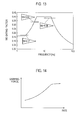
- FIG. 15 is a graph illustrating a wheel speed frequency characteristic detected by the wheel speed sensor under a certain traveling condition.
- FIG. 16 is a block diagram illustrating a control configuration of unsprung vibration suppression control according to the first embodiment.
- FIG. 17 is a control block diagram illustrating a control configuration of the damping force control unit according to the first embodiment.
- FIG. 18 is a flowchart illustrating damping coefficient arbitration processing in a standard mode according to the first embodiment.
- FIG. 19 is a flowchart illustrating the damping coefficient arbitration processing in a sports mode according to the first embodiment.
- FIG. 20 a flowchart illustrating the damping coefficient arbitration processing in a comfort mode according to the first embodiment.
- FIG. 21 is a flowchart illustrating the damping coefficient arbitration processing in a highway mode according to the first embodiment.
- FIG. 22 is a time chart illustrating changes of the damping coefficient when traveling on a wave road surface and an uneven road surface.
- FIG. 23 is a flowchart illustrating mode selection processing based on a traveling state in a damping coefficient arbitration unit according to the first embodiment.
- FIG. 24 is a control block graph illustrating each actuator control amount calculation processing when performing pitch control according to the first embodiment.
- FIG. 1 is a system schematic view illustrating a control apparatus for a vehicle according to a first embodiment.
- the vehicle includes an engine 1 serving as a driving power source, brakes 20 (hereinafter, when a brake corresponding to an individual wheel is displayed, described as a right front-wheel brake: 20 FR, a left front-wheel brake: 20 FL, a right rear-wheel brake: 20 RR, and a left rear-wheel brake: 20 RL) each of which generates braking torque due to a frictional force to each wheel, shock absorbers 3 each of which is provided between each wheel and a vehicle body and can control a damping force in an adjustable manner (hereinafter, described as S/A, and when an S/A corresponding to an individual wheel, the S/A is described as a right front-wheel S/A 3 FR, a left front-wheel S/A 3 FL, a right rear-wheel S/A 3 RR, and a left rear-wheel S/A 3 RL).
- brakes 20 hereinafter, when
- the engine 1 includes an engine controller (hereinafter, referred to as also an engine control unit) la configured to control torque outputted from the engine 1 .
- the engine controller 1 a controls the degree of opening of a throttle valve, the fuel injection quantity, ignition timing, and the like, of the engine 1 , to control a desired engine operation state (the engine speed or the engine output torque).
- the brake 20 generates a braking torque based on a hydraulic pressure supplied from a brake control unit 2 that can control a brake hydraulic pressure of each wheel according to each traveling state.
- the brake control unit 2 includes a brake controller (hereinafter, referred to as also a brake control unit) 2 a configured to control the braking torque generated by the brake 20 .
- the brake control unit 2 includes a brake controller 2 a configured to control the braking torque generated by the brake 20 , and uses a master cylinder pressure generated through a brake pedal operation by a vehicle driver or a pump pressure generated by a built-in motor driving pump as a hydraulic pressure source, to generate a desired hydraulic pressure at the brake 20 of each wheel through opening and closing operations by a plurality of electromagnetic valves.
- S/A 3 is a damping force generation device configured to decrease an elastic motion of a coil spring provided between an unsprung portion (axles, wheels, or the like) and a sprung portion (a vehicle body or the like), of the vehicle, and is configured to vary a damping force in an adjustable manner by an operation of an actuator.
- S/A 3 includes a cylinder into which a fluid is enclosed, a piston which slides up and down inside the cylinder, and an orifice configured to control the fluid movement between fluid chambers formed above and below the piston.
- orifices having several types of orifice diameters are formed on the piston, and when the S/A actuator is being operated, an orifice in accordance with a control command is selected from the several types of orifices.
- a damping force may be set, for example, such that an electromagnetic control valve is arranged on a communicating path which connects the fluid chambers formed above and below the piston, and the opening and closing amount of the electromagnetic control valve is controlled.
- the way to set a damping force is not especially limited.
- S/A 3 includes an S/A controller 3 a (corresponding to a damping force control unit) configured to control a damping force of S/A 3 , and controls the damping force to cause the S/A actuator to activate the orifice diameter.
- the vehicle includes wheel speed sensors 5 (hereinafter, when a wheel speed corresponding to an individual wheel is displayed, described as a right front-wheel speed: 5 FR, a left front-wheel speed: 5 FL, a right rear-wheel speed: 5 RR, a left rear-wheel speed: and 5 RL) each of configured to detect a wheel speed of each wheel, an integrated type sensor 6 configured to detect a longitudinal acceleration acting on the gravity center of the vehicle, a yaw rate, and a lateral acceleration, a steering angle sensor 7 configured to detect an operating steering angle serving as a steering operation amount by the vehicle driver, a vehicle speed sensor 8 configured to detect a vehicle speed, an engine torque sensor 9 configured to detect engine torque, an engine speed sensor 10 configured to detect an engine speed, a master pressure sensor 11 configured to detect a master cylinder pressure, a brake switch 12 configured to output an on-state signal when a brake pedal operation is performed, and an accelerator opening degree sensor 13 configured to detect an accelerator pedal opening degree.
- wheel speed sensors 5 hereinafter, when a
- the integrated type sensor 6 may be arranged at a position of the center of gravity of the vehicle, or may be arranged at another position as long as the configuration of various kinds of values at the position of the center of gravity can be estimated.
- the arrangement of the integrated type sensor 6 is not especially limited.
- the sensor 6 is not necessarily to an integrated type, and may be configured to detect a yaw rate, a longitudinal acceleration, and a lateral acceleration separately.
- FIG. 2 is a control block diagram illustrating a control configuration of the control apparatus for a vehicle according to the first embodiment.
- a controller includes three controllers of the engine controller 1 a , a brake controller 2 a , and the S/A controller 3 a.
- the S/A controller 3 a includes a driver-input control unit 31 configured to perform driver-input control for attaining a desired vehicle attitude based on operations (steering operation, accelerator operation and brake pedal operation or the like) by the vehicle driver, a traveling-state estimator 32 configured to estimate a traveling state based on the detection values by the various kinds of sensors, a sprung vibration suppression control unit 33 configured to control a sprung vibration state based on the estimated traveling state, an unsprung vibration suppression control unit 34 configured to control an unsprung vibration state based on the estimated traveling state, and a damping force control unit 35 configured to determine, based on the shock absorber attitude control amount outputted from the driver-input control unit 31 , the sprung vibration suppression control amount outputted from the sprung vibration suppression control unit 33 , and the unsprung vibration suppression control amount outputted from the unsprung vibration suppression control unit 34 , a damping force to be set to S/A 3 , and controls the damping force of S/A.
- a driver-input control unit 31 configured to perform
- the controller may include four controllers by excluding the damping force control unit 35 from the S/A controller 3 a and using the resulting S/A controller 3 a as an attitude controller and using the damping force control unit 35 as the S/A controller, or all the respective controllers may constitute one integral controller.
- the configuration of the controllers is not particularly limited. Note that the reason why such a configuration is employed in the first embodiment is because it is assumed that the control apparatus for a vehicle in the first embodiment is implemented by using an engine controller and a brake controller in an existing vehicle without any change as the engine controller 1 a and the brake controller 2 a , and separately mounting the S/A controller 3 a.
- the control apparatus for a vehicle in the first embodiment uses three actuators for controlling a vibration state generated on the sprung portion.
- the sprung state is controlled by the respective actuators, thereby causing a problem of mutual interference.
- control elements which can be controlled by the engine 1 , the brake 20 , and S/A 3 are different from one another, thereby causing a problem that how to combine these control elements for performing the control.
- the brake 20 can control the bounce movement and the pitch movement
- the control of both the movements causes the strong sense of deceleration, thereby easily giving a discomfort feeling to a vehicle driver.
- S/A 3 can control all of the roll movement, the bounce movement, and the pitch movement.
- performing all the control by S/A 3 results in increasing the manufacturing cost for S/A 3 , and a tendency of an increased damping force, high frequency vibration from the road surface side is likely to be inputted, thereby also easily giving a discomfort feeling to the vehicle driver.
- the overall control system thereof is constructed by considering the points listed below.
- the control by the engine 1 and the control by the brake 20 are performed with priority to suppress the control amount by S/A 3 .
- the control object movement of the brake 20 is limited to the pitch movement to resolve the sense of deceleration due to the control by the brake 20 .
- the control amounts by the engine 1 and the brake 20 are limited than the control amount which can be actually outputted, thereby suppressing a discomfort feeling generated with the control by the engine 1 or the brake 20 while reducing burden on S/A 3 .
- the skyhook control is achieved with an inexpensive configuration using a wheel speed sensor currently mounted in all the vehicles, without using a stroke sensor, a sprung vertical acceleration sensor, or the like usually required for the skyhook control.
- the driver-input control unit 31 includes: an engine-side driver-input control unit 31 a configured to attain a vehicle attitude, which a vehicle driver requests, by torque control of the engine 1 ; and an S/A-side driver-input control unit 31 b configured to attain a vehicle attitude, which a vehicle driver requests, by damping force control of S/A 3 .
- the engine-side driver-input control unit 31 a calculates a grounding-load fluctuation suppression control amount for suppressing grounding-load fluctuations between front-wheels and rear-wheels, and a yaw response control amount corresponding to a vehicle behavior that the vehicle driver intends to attain based on a signal from the steering angle sensor 7 or the vehicle speed sensor 8 ( a )nd outputs the same to the engine control unit 1 a.
- the S/A-side driver-input control unit 31 b calculates a driver input damping force control amount corresponding to a vehicle behavior that the vehicle driver intends to attain based on a signal from the steering angle sensor 7 or the vehicle speed sensor 8 ( a )nd outputs the driver input damping force control amount to the damping force control unit 35 .
- the S/A-side driver-input control unit 31 b outputs the damping force of four wheels as a driver input damping force control amount to prevent the nose from being lifted.
- the S/A-side driver-input control unit 31 b outputs a driver input damping force control amount for suppressing the roll generated during the turning.
- FIG. 3 is a control block diagram illustrating a control configuration of roll rate suppression control in the first embodiment.
- a lateral acceleration estimator 31 b 1 estimates a lateral acceleration Yg based on a front-wheel steering angle ⁇ f detected by the steering angle sensor 7 , a rear-wheel steering angle ⁇ r (that may be an actual rear wheel steering angle when provided with a rear-wheel steering device, otherwise zero as required), and a vehicle speed VSP detected by the vehicle speed sensor 8 .
- This lateral acceleration Yg is calculated by the following equation using an estimated yaw rate value ⁇ .
- Yg VSP ⁇
- the estimated Yaw rate value ⁇ is calculated by the following equations.
- a 90° phase lead component generation unit 31 b 2 differentiates an estimated lateral acceleration Yg and outputs the result as a lateral acceleration differential value dYg.
- a 90° phase lag component generation unit 31 b 3 outputs a component F(dYg), which is obtained by delaying the phase of the lateral acceleration differential value dYg by 90°.
- the component F(dYg) is a component obtained by bringing back the phase of the lateral acceleration differential value dYg, whose component in a low frequency region is removed by the 90° phase lead component generation unit 31 b 2 , to the phase of the lateral acceleration Yg, and is a DC-cut component of the lateral acceleration Yg, i.e., a transitional component of the lateral acceleration Yg.
- a 90° phase lag component generation unit 31 b 4 outputs a component F(Yg), which is obtained by delaying the phase of the estimated lateral acceleration Yg by 90°.
- a gain multiplication unit 31 b 5 multiplies the lateral acceleration Yg, the lateral acceleration differential value dYg, the lateral acceleration DC cut component F (dYg), and the 90° phase lag component F (Yg) by a gain, respectively.
- Each gain is set based on a roll rate transfer function of an operating steering angle. Moreover, each gain may be adjusted in accordance with four control modes described later.
- a square calculation unit 31 b 6 squares each component multiplied by a gain and outputs this result.
- a summation unit 31 b 7 sums up the values which the square calculation unit 31 b 6 outputted.
- a gain multiplication unit 31 b 8 multiplies a square value of the summed up components by a gain and outputs this result.
- a square root calculation unit 31 b 9 calculates a driver input attitude control amount for roll rate suppression control by calculating a square root of the value which the gain multiplication unit 31 b 7 outputted, and outputs this result to the damping force control unit 35
- the 90° phase lead component generation unit 31 b 2 , the 90° phase lag component generation unit 31 b 3 , the 90° phase lag component generation unit 31 b 4 , the gain multiplication unit 31 b 5 , the square calculation unit 31 b 6 , the summation unit 31 b 7 , the gain multiplication unit 31 b 8 ( a )nd the square root calculation unit 31 b 9 correspond to a Hilbert conversion unit 31 b 10 that generates an envelopment waveform using Hilbert conversion.
- FIG. 4 is a time chart illustrating envelope waveform forming processing in the roll rate suppression control in the first embodiment.
- a 90° phase lead component is added to form an envelope waveform, and a driver input attitude control amount is calculated on the basis of the scalar quantity based on the envelope waveform, thereby making it possible to suppress the roll rate from generating at the initial steering.
- the lateral acceleration DC cut component F(dYg) is added to form an envelopment waveform, thereby enabling to efficiently suppress a roll rate that occurs in a transient condition when a vehicle driver starts or completes steering.
- a stationary turning state in which the generation of a roll is stable, degradation of the ride comfort can be prevented without excessively increasing the damping force.
- FIG. 5 is a control block diagram illustrating the configuration of the traveling state estimator according to the first embodiment.
- the traveling state estimator 32 according to the first embodiment basically based on the wheel speed detected by the wheel speed sensor 5 , calculates a stroke speed, a bounce rate, a roll rate, and a pitch rate of each wheel used for the skyhook control by the sprung vibration suppression control unit 33 described later.
- the value of the wheel speed sensor 5 of each wheel is inputted to a stroke speed calculation unit 321 , and a sprung speed is calculated from the stroke speed of each wheel calculated by the stroke speed calculation unit 321 .
- FIG. 6 is a control block diagram illustrating control contents in the stroke speed calculation unit according to the first embodiment.
- the stroke speed calculation unit 321 is separately provided for each wheel, and the control block diagram illustrated in FIG. 6 is a control block diagram focused on a certain wheel.
- the stroke speed calculation unit 321 includes: a reference wheel speed calculation unit 300 configured to calculate the wheel speed serving as the reference, based on the value of the wheel speed sensor 5 , the front wheel steering angle ⁇ f and the rear wheel steering angle ⁇ r (which may be an actual rear wheel steering angle when provided with a rear-wheel steering device, otherwise zero as required) detected by the steering angle sensor 7 , the vehicle body lateral speed, and the actual yaw rate detected by the integrated type sensor 6 ; a tire rotational vibration frequency calculation unit 321 a configured to calculate a tire rotational vibration frequency based on the calculated reference wheel speed; a deviation calculation unit 321 b configured to calculate a deviation (wheel speed fluctuation) between the reference wheel speed and the wheel speed sensor value; a GEO conversion unit 321 c configured to convert the deviation calculated by the deviation calculation unit 321 b to a suspension stroke quantity; a stroke speed calibration unit 321 d configured to calibrate the converted stroke quantity to a stroke speed; and a signal processor 321 e that removes a tire rotation
- FIG. 7 is a block diagram illustrating the configuration of the reference wheel speed calculation unit according to the first embodiment.
- the reference wheel speed refers to the value of each wheel speed after removing various kinds of disturbances.
- a difference between the wheel speed sensor value and the reference wheel speed is a value related to a component that fluctuates in response to a stroke generated by the bounce behavior, the roll behavior, the pitch behavior of a vehicle body or by the unsprung vertical vibration.
- the stroke speed is estimated based on this difference.
- a planar motion component extract unit 301 calculates a first wheel speed V0 serving as the reference wheel speed of each wheel, based on a vehicle body plan view model with the wheel speed sensor value as an input.
- the wheel speed sensor value detected by the wheel speed sensor 5 is denoted as ⁇ (rad/s)
- the front wheel actual steering angle detected by the steering angle sensor 7 as ⁇ f(rad)
- the vehicle body lateral speed as Vx the yaw rate detected by the integrated type sensor 6 as ⁇ (rad/s)
- the reference wheel speeds to be calculated as VFL, VFR, VRL, and VRR a tread of the front wheel as Tf, a tread of the rear wheel as Tr, a distance from the center of gravity position of the vehicle to the front wheel as Lf, and a distance from the center of gravity position of the vehicle to the front wheel as Lr.
- VFL ( V ⁇ Tf/ 2 ⁇ )cos ⁇ f +( Vx+Lf ⁇ )sin ⁇ f
- VFR ( V+Tf/ 2 ⁇ )cos ⁇ f +( Vx+Lf ⁇ )sin ⁇ f
- VRL ( V ⁇ Tr/ 2 ⁇ )cos ⁇ r +( Vx ⁇ Lr ⁇ )sin ⁇ r
- VRR ( V+Tr/ 2 ⁇ )cos ⁇ r +( Vx ⁇ Lr ⁇ )sin ⁇ r
- V is denoted as V0FL, V0FR, V0RL, and V0RR (corresponding to the first wheel speeds), as the values corresponding to the respective wheels.
- V 0 FL ⁇ VFL ⁇ Lf ⁇ sin ⁇ f ⁇ /cos ⁇ f+Tf/ 2 ⁇
- V 0 FR ⁇ VFR ⁇ Lf ⁇ sin ⁇ f ⁇ /cos ⁇ f ⁇ Tf/ 2 ⁇
- V 0 RL ⁇ VRL+Lr ⁇ sin ⁇ r ⁇ /cos ⁇ r+Tr/ 2 ⁇
- V 0 RR ⁇ VRR+Lf ⁇ sin ⁇ f ⁇ /cos ⁇ r ⁇ Tr/ 2 ⁇
- a roll disturbance removing unit 302 calculates, based on a vehicle body front view model, second wheel speeds V0F and V0R serving as the reference wheel speeds of the front and rear wheels, with the first wheel speed V0 as an input.
- the vehicle body front view model is for removing a difference between wheel speeds that is caused by a roll movement occurring around the center of roll rotation on a vertical line passing the center of gravity of the vehicle when the vehicle is seen from the front. This is expressed with the equation below.
- V 0 F ( V 0 FL+V 0 FR )/2
- V 0 R ( V 0 RL+V 0 RR )/2
- the second wheel speeds V0F and V0R after removing the disturbance caused by the roll are obtained.
- a pitch disturbance removing unit 303 calculates, based on a vehicle body side view model, third wheel speeds VbFL, VbFR, VbRL, and VbRR serving as the reference wheel speeds for all the wheels, with the second wheel speeds V0F and V0R as inputs.
- the vehicle body side view model is for removing an error that is caused by a pitch movement occurring around the center of pitch rotation on the vertical line passing the center of gravity of the vehicle when the vehicle is seen from a lateral direction. This is expressed with the equation below.
- a deviation between this reference wheel speed ⁇ 0 and the wheel speed sensor value is calculated, and is converted to a stroke speed Vz_s because this deviation is a wheel speed fluctuation associated with the stroke of a suspension.
- the suspension in holding each wheel, will not stroke only in a vertical direction, but the wheel rotation center moves longitudinally along with the stroke and at the same time an axle itself having the wheel speed sensor 5 mounted thereon has a gradient and generates a rotational angle difference with respect to a wheel. Because the wheel speed varies with this longitudinal movement, the deviation between the reference wheel speed and the wheel speed sensor value can be extracted as a fluctuation associated with this stroke. Note that how much fluctuation is generated may be appropriately set in accordance with the geometry of the suspension.
- the sprung speed calculation unit 322 calculates a bounce rate, a roll rate, and a pitch rate for skyhook control.
- the skyhook control sets a damping force based on the relation between the stroke speed and the sprung speed of S/A 3 to perform sprung attitude control, thereby attaining a flat traveling state.
- it is required to feedback the sprung speed.
- the value detectable from the wheel speed sensor 5 is the stroke speed and the sprung portion does not include a vertical acceleration sensor or the like, the sprung speed needs to be estimated using an estimation model.
- an estimation model a problem of the estimation model and the model configuration to be employed is explained.
- FIGS. 8( a ) and 8 ( b ) are schematic views illustrating a vehicle body vibration model.
- FIG. 8( a ) illustrates a model of the vehicle which is provided with S/A of a constant damping force (hereinafter, described as conventional vehicle), and
- FIG. 8( b ) shows a model of the vehicle which is provided with S/A of a variable damping force and performs skyhook control.
- S/A of a constant damping force hereinafter, described as conventional vehicle
- FIG. 8( b ) shows a model of the vehicle which is provided with S/A of a variable damping force and performs skyhook control.
- Ms represents a sprung mass
- Mu represents an unsprung mass
- Ks represents an elastic coefficient of a coil spring
- Cs represents a damping coefficient of S/A
- Ku represents an elastic coefficient of an unsprung portion (tire)
- Cu represents a damping coefficient of the unsprung portion (tire)
- Cv represents a variable damping coefficient.
- z2 represents a sprung position
- z1 represents an unsprung position
- z0 represents a road surface position.
- dz1 represents first order differentiation of z1 (that is speed), and ddz1 represents second order differentiation thereof (that is acceleration).
- Ms ⁇ ddz 2 ⁇ Ks ( z 2 ⁇ z 1) ⁇ Cs ( dz 2 ⁇ dz 1)
- dz 2 ⁇ (1/ Ms ) ⁇ (1/ s 2) ⁇ ( Cs ⁇ s+Ks )( dz 2 ⁇ dz 1)
- dz2 ⁇ dz1 is the stroke speed (Vz_sFL, Vz_sFR, Vz_sRL, and Vz_sRR)
- a sprung speed can be calculated from the stroke speed.
- change of a damping force by the skyhook control remarkably lowers the estimation accuracy. This raises a problem that a large attitude control force (damping force change) cannot be applied by the conventional vehicle model.
- the vehicle model by the skyhook control such as that shown in FIG. 8( b ) is used.
- Change of a damping force basically means to change a force of limiting the piston traveling speed of S/A 3 with the suspension stroke. Because the semi-active S/A 3 which cannot actively move the piston toward a desired direction is used, a semi-active skyhook model is employed to obtain a sprung speed.
- An equation is expressed as follows.
- a sprung speed is estimated using an active skyhook model which does not depend on the code relation between the sprung speed and the stroke speed, and is possible to directly use Csky with stability.
- the active skyhook model is employed to obtain a sprung speed.
- differentiation dxsB and so on of xsB, xsR, xsP, and xsW are expressed by the following equations.
- dxsB 1 ⁇ 4( Vz — sFL+Vz — sFR+Vz — sRL+Vz — sRR )
- dxsR 1 ⁇ 4( Vz — sFL ⁇ Vz — sFR+Vz — sRL ⁇ Vz — sRR )
- dxsP 1 ⁇ 4( ⁇ Vz — sFL ⁇ Vz — sFR+Vz — sRL+Vz — sRR )
- dxsW 1 ⁇ 4( ⁇ Vz — sFL+Vz — sFR+Vz — — sRL ⁇ Vz — sRR )
- the sprung vibration suppression control unit 33 includes: the skyhook control unit 33 a configured to perform the attitude control based on the above-described sprung speed estimate value; and the frequency-sensitive control unit 33 b configured to suppress the sprung vibration based on a road surface input frequency.
- the control apparatus for a vehicle includes three actuators for attaining the sprung attitude control as follows: an actuator for the engine 1 ; an actuator for the brake 20 ; and an actuator for S/A 3 .
- the bounce rate, the roll rate, and the pitch rate are set as three control objects for S/A 3
- the bounce rate and pitch rate are set as the control objects for the engine 1
- the pitch rate is set as the control object for the brake 20 .
- a control amount common to the respective actuators needs to be used.
- the control amount with respect to each actuator can be determined using the sprung speed estimated by the above-described traveling state estimator 32 .
- FB is transmitted to the engine 1 and S/A 3 as the bounce attitude control amount, while FR is transmitted to the damping force control unit 35 as the roll attitude control amount because FR is controlled only in S/A 3 .
- the pitch control is performed by the engine 1 , the brake 20 , and S/A 3 .
- the control amounts of the engine 1 and the brake 20 are increased more than during normal time so as to perform the pitch control only by the engine 1 and the brake 20 .
- the pitch control is performed by the engine 1 , the brake 20 , and S/A 3 .
- the control amounts of the engine 1 and the brake 20 are increased more than during normal time so as to reduce the control amount by S/A 3 less than during normal time.
- FIG. 9 is a control block diagram illustrating each actuator control amount calculation processing in performing pitch control according to the first embodiment.
- the skyhook control unit 33 a includes a first target attitude control amount calculation unit 331 configured to calculate a target pitch rate that is the first target attitude control amount that is the control amount available in common to all the actuators.
- the skyhook control unit 33 a includes an abnormality detection unit 337 configured to detect an abnormality of S/A 3 .
- an engine attitude control amount calculation unit 332 configured to calculate the engine attitude control amount attained by the engine 1
- a brake attitude control amount calculation unit 334 configured to calculate the brake attitude control amount attained by the brake 20
- an S/A attitude control amount calculation unit 336 configured to calculate the S/A attitude control amount attained by S/A 3 calculate the respective attitude control amounts.
- an engine attitude control amount calculation unit 332 b configured to calculate the engine attitude control amount attained by the engine 1
- a brake attitude control amount calculation unit 334 b configured to calculate the brake attitude control amount attained by the brake 20
- an S/A attitude control amount calculation unit 336 b configured to calculate the S/A attitude control amount attained by S/A 3 calculate the respective attitude control amounts.
- the first target attitude control amount calculation unit 331 outputs a pitch rate as it is (hereinafter, this pitch rate is referred to as a first target attitude control amount).
- the damping force control unit 35 monitors S/A 3 , and outputs a fail signal to the abnormality detection unit 337 when S/A 3 stops to operate due to a failure or when the variable range of the damping force becomes narrow (hereinafter, when S/A is abnormal).
- a switch 338 outputs the first target attitude control amount, which is calculated by the first target attitude control amount calculation unit 331 , to the brake attitude control amount calculation unit 334 during normal time, while when the abnormality detection unit 337 detects the fail signal, the switch 338 outputs the same to the engine attitude control amount calculation unit 332 b.
- the brake attitude control amount calculation unit 334 calculates, based on an inputted first target attitude control amount, a brake attitude control amount that is the control amount that can be attained by the brake.
- a limit value for limiting the brake attitude control amount is set so as not to give any sense of discomfort to the vehicle driver. This limits the brake attitude control amount so as to be within a predetermined range of longitudinal acceleration when converted to a longitudinal acceleration. Accordingly, the brake attitude control amount calculation unit 334 calculates a brake attitude control amount based on the first target attitude control amount, and outputs, when the value thus calculated is equal to or greater than the limit value, a brake attitude control amount that can be attained by the limit value.
- the brake attitude control amount outputted from the brake attitude control amount calculation unit 334 is outputted as a value obtained by multiplying the pitch rate suppressed by the brake 20 by CskyP.
- a value converted into a pitch rate by a conversion unit 334 a is outputted.
- the brake control unit 2 a calculates a braking torque control amount based on the brake attitude control amount corresponding to the limit value, and outputs the braking torque control amount to the brake control unit 2 .
- the second target attitude control amount calculation unit 333 calculates a second target attitude control amount that is a deviation between the first target attitude control amount and a value (hereinafter, this value is simply referred also as a brake attitude control amount) obtained by converting the brake attitude control amount into a pitch rate by the conversion unit 334 a , and outputs the second target attitude control amount to the engine attitude control amount calculation unit 332 .
- a limit value for limiting an engine attitude control amount is set so as not to give any sense of discomfort to the vehicle driver, as with the brake 20 . This limits the engine attitude control amount so as to be within a predetermined range of longitudinal acceleration when converted to a longitudinal acceleration. Accordingly, the second target attitude control amount calculation unit 333 calculates the engine attitude control amount based on the second target attitude control amount and outputs, when the value thus calculated is equal to or greater than the limit value, an engine attitude control amount that can be attained by the limit value.
- the engine attitude control amount outputted from the engine attitude control amount calculation unit 332 is outputted as a value obtained by multiplying the pitch rate suppressed by the engine 1 by CskyP.
- a value which is obtained by converting the engine attitude control amount into a pitch rate by a conversion unit 332 a , is outputted.
- the engine control unit 1 a calculates an engine torque control amount based on the engine attitude control amount corresponding to the limit value, and outputs the engine torque control amount thus calculated to the engine 1 .
- the third target attitude control amount calculation unit 335 calculates a third target attitude control amount that is a deviation between the second target attitude control amount and a value (hereinafter, this value is simply referred also as an engine attitude control amount) obtained by converting the engine attitude control amount into the pitch rate by the conversion unit 332 a , and outputs the third target attitude control amount to an S/A attitude control amount calculation unit 336 .
- the S/A attitude control amount calculation unit 336 outputs a pitch attitude control amount corresponding to the third target attitude control amount.
- the damping force control unit 35 calculates a damping force control amount based on the bounce attitude control amount, the roll attitude control amount, and the pitch attitude control amount (hereinafter, these are collectively referred to as an S/A attitude control amount), and outputs the same to S/A 3 .
- the engine attitude control amount calculation unit 332 b calculates, based on an inputted first target attitude control amount, the engine attitude control amount that is a control amount that can be attained by the engine 1 .
- a limit value for limiting an engine attitude control amount is set, as with the engine attitude control amount calculation unit 332 .
- the limit value of the engine attitude control amount calculation unit 332 b is set larger than the limit value of the engine attitude control amount calculation unit 332 . This enables to increase the engine attitude control amount and suppress the pitch rate even if the control amount by S/A 3 decreases when S/A is abnormal.
- a value converted into the pitch rate by the conversion unit 332 c is outputted.
- the engine attitude control amount calculation unit 332 b calculates an engine attitude control amount so as to increase the control responsiveness of the engine 1 more than during normal time. Because S/A 3 is the portion directly related to the vehicle body attitude, the attitude control by S/A 3 immediately appears as a change in the vehicle body attitude. On the other hand, the attitude control by the engine 1 is slow as compared with the attitude control by S/A 3 because the result of applying an acceleration/deceleration to the vehicle appears as a change in the vehicle body attitude. When S/A is abnormal, the attitude control by S/A 3 might not sufficiently be performed and therefore by increasing the control responsiveness of the engine 1 , it is possible to suppress decrease of the responsiveness of the vehicle body attitude control. Moreover, the engine control unit 1 a calculates an engine torque control amount based on the engine attitude control amount corresponding to the limit value, and outputs the same to the engine 1 .
- the second target attitude control amount calculation unit 333 b calculates a second target attitude control amount that is a deviation between the first target attitude control amount and a value, which is obtained by converting the engine attitude control amount into the pitch rate by the conversion unit 332 c , and outputs the same to a brake attitude control amount calculation unit 334 b.
- a limit value for limiting the brake attitude control amount is set, as with the brake attitude control amount calculation unit 334 .
- the limit value of the brake attitude control amount calculation unit 334 b is set larger than the limit value of the brake attitude control amount calculation unit 334 . This enables to increase the brake attitude control amount and suppress the pitch rate even if the control amount by S/A 3 decreases when S/A is abnormal.
- a value converted into the pitch rate by the conversion unit 332 c is outputted.
- the brake attitude control amount calculation unit 334 b calculates a brake attitude control amount so as to increase the control responsiveness of the brake 20 more than during normal time.
- the attitude control by the brake 20 is slow as compared with the attitude control by S/A 3 because a result of applying deceleration to the vehicle appears as a change in the vehicle body attitude.
- S/A is abnormal, the attitude control by S/A 3 might not sufficiently be performed and therefore by increasing the control responsiveness of the brake 20 , it is possible to suppress decrease of the responsiveness of the vehicle body attitude control.
- the brake control unit 2 a calculates a braking torque control amount based on the brake attitude control amount corresponding to the limit value, and outputs the same to the brake control unit 2 .
- the third target attitude control amount calculation unit 335 calculates a third target attitude control amount that is a deviation between the second target attitude control amount and a value, which is obtained by converting the brake attitude control amount into the pitch rate, and outputs the same to the S/A attitude control amount calculation unit 336 .
- the S/A attitude control amount calculation unit 336 outputs a pitch attitude control amount corresponding to the third target attitude control amount.
- the damping force control unit 35 calculates a damping force control amount based on the bounce attitude control amount, the roll attitude control amount, and the pitch attitude control amount (the S/A attitude control amount), and outputs the same to S/A 3 .
- the first target attitude control amount is calculated, and then the brake attitude control amount is calculated, the engine attitude control amount is calculated from the second target attitude control amount that is the deviation between the first target attitude control amount and the brake attitude control amount, and the S/A attitude control amount is calculated from the third target attitude control amount that is the deviation between the second attitude control amount and the engine attitude control amount.
- the amount of the pitch rate control performed by S/A 3 can be reduced by the control of the engine 1 and the brake 20 , and therefore the controllable range of S/A 3 can be set relatively narrow and the sprung attitude control can be attained with an inexpensive S/A 3 .
- the damping force would basically increase.
- An increase of the damping force means a hard suspension property, and therefore when a high-frequency vibration is inputted from the road surface side, the high frequency input is likely to be transmitted, thus impairing the comfort of occupants (hereinafter, referred to as a deterioration of the high frequency vibration characteristic).
- the actuators such as the engine 1 and the brake 20 , which do not have an influence on the vibration transmission characteristics due to a road surface input, can suppress the pitch rate and reduce the control amount of S/A 3 , thereby preventing the deterioration of the high-frequency vibration characteristic.
- the above-described effects can be obtained by determining the control amount of the engine 1 prior to S/A 3 and by determining the control amount of the brake 20 prior to S/A 3 .
- the bounce rate and the pitch rate are set as the control objects for the engine 1 and the pitch rate is set as the control object for the brake 20 , and therefore by determining the control amount of the brake 20 prior to the engine 1 , it is possible to reduce the control amount of the pitch control by the engine 1 and thus the engine 1 can concentrate on the bounce control.
- the limit value of the engine torque control amount and the limit value of the braking torque control amount are set larger than during normal time.
- the amount of the pitch rate control performed by S/A 3 can be further reduced by the control of the engine 1 and the brake 20 , and therefore the sprung attitude control can be attained even when the controllable range becomes narrower due to a failure of S/A 3 than during normal time.
- the limit value of the braking torque control amount is set larger, a strong sense of discomfort due to an unintended sense of deceleration might be given to the vehicle driver.
- the sense of acceleration/deceleration is small and the sense of discomfort which the vehicle driver feels is also small. Therefore, when S/A is abnormal, an increase in the sense of deceleration can be prevented by determining the control amount of the engine 1 prior to the brake 20 and reducing the control amount of the brake 20 .
- FIG. 10 is a control block diagram illustrating brake pitch control in the first embodiment.
- a mass of the vehicle body is m
- a front-wheel braking force is BFf
- a rear-wheel braking force is BFr
- a height between the vehicle gravity center and the road surface is Hcg
- an acceleration of the vehicle is a
- a pitch moment is Mp
- a pitch rate is Vp
- the braking force is applied when the pitch rate Vp is positive, that is, when the front-wheel side is depressed, the front-wheel side is further depressed to promote the pitch motion. Accordingly, in this case, no braking force is applied.
- the pitch rate Vp is negative, that is, the front-wheel side is lifted, the braking pitch moment applies a braking force to suppress the front-wheel side from being lifted. This secures a field of vision of the vehicle driver, and allows the vehicle driver to easily see the forward to contribute to improve the sense of security and the sense of flatness. From the above, the control amounts below are applied.
- braking torque is generated only when the front side of the vehicle body is lifted. This enables the reduced deceleration to be generated compared with a case where braking torque is generated in both of the cases where the front side of the vehicle body is lifted and depressed. Moreover, only a half of the frequency of actuator operations is needed, thereby making it possible to employ the low-cost actuator.
- the brake attitude control amount calculation unit 334 includes the following control blocks.
- a dead zone processing code determining unit 3341 determines the inputted code of the pitch rate Vp to output 0 to a deceleration sense reducing processor 3342 if the code is positive because no control is required, and outputs a pitch rate signal the deceleration sense reducing processor 3342 if the code is negative because it is determined that control is possible.
- a square processor 3342 a squares a pitch rate signal. This inverts the sign and also smoothes the rising edge of a control force.
- a pitch rate square damping moment calculation unit 3342 b calculates a pitch moment Mp by multiplying the squared pitch rate by the skyhook gain CskyP of the pitch term taking into consideration the squaring.
- a target deceleration calculating unit 3342 c calculates a target deceleration by dividing the pitch moment Mp by the mass m and by the height Hcg between the center of gravity of the vehicle and the road surface.
- a jerk threshold value limiting unit 3342 d determines whether or not the change rate of the calculated target deceleration, that is, a jerk is within the ranges of the deceleration jerk threshold value and the remove jerk threshold value which are set in advance, and the target deceleration is within the range of the longitudinal acceleration limit value. If the jerk exceeds either of the threshold values, the target deceleration is corrected to be a value within the range of the jerk threshold value, and if the target deceleration exceeds the limit value, the target deceleration is set within the range of the limit value. This allows a deceleration to be generated in such a manner that no discomfort feeling is given to the vehicle driver.
- a target pitch moment conversion unit 3343 calculates a target pitch moment by multiplying the target deceleration limited in the jerk threshold value limiting unit 3342 d by the mass m and the height Hcg, and outputs the target pitch moment to the brake controller 2 a and a target pitch rate conversion unit 334 a .
- the target pitch rate conversion unit 334 a divides the target pitch moment by the skyhook gain CskyP of the pitch term and converts the same to a target pitch rate (corresponding to the brake attitude control amount), and outputs the target pitch rate to the third target attitude control amount calculation unit 335 .
- the sprung vibration suppression control is attained by estimating a sprung speed basically on the basis of the detection value by the wheel speed sensor 5 and performing the skyhook control based on the sprung speed.
- the wheel speed sensor 5 may not assure the sufficient estimation accuracy, or a case where depending on the traveling status or the intention by the vehicle driver, a comfortable traveling state (not the sense of flatness of the vehicle body but a gentler and comfortable ride) is intended to be actively assured.
- a slight phase displacement might cause difficulty of adequate control in vector control in which the relation (phase or the like) between the signs of the stroke speed and the sprung speed such as the skyhook control. Accordingly, frequency-sensitive control that is sprung vibration suppression control in accordance with the scalar quantity of vibration characteristics has been decided to be introduced.
- FIG. 11 is a graph depicting both the wheel speed frequency characteristic detected by a wheel speed sensor and the stroke frequency characteristic by a stroke sensor that is not mounted in the embodiment.
- the frequency characteristic is a characteristic, in which the magnitude of the amplitude with respect to the frequency is expressed by a vertical axis as a scalar quantity.
- a region where a sprung resonant frequency component is present is defined as a frequency region “fuwa” (0.5 to 3 Hz).
- the region “fuwa” is a frequency region that brings a sense of an occupant being thrown into the air because the entire body of the occupant is swung, in other words, a sense of decrease of the gravitational acceleration acting on the occupant.
- a region between the sprung resonant frequency component and the unsprung resonant frequency component is defined as a frequency region “hyoko” (3 to 6 Hz).
- the region “hyoko” is a frequency region which brings not a sense of decrease of the gravitational acceleration but a sense of wigglingly jumping of a human body in trotting a horse, in other words, which brings a vertical movement which the entire body can follow.
- a region where the unsprung resonant frequency component is present is defined as a frequency region “buru” (6 to 23 Hz).
- the region “buru” is a frequency region where not a vertical movement which the mass of a human body can follow but wiggling vibration is transmitted to a part of the body such as thighs of the occupant.
- FIG. 12 is a control block diagram illustrating frequency-sensitive control in the sprung vibration suppression control in the first embodiment.
- a band elimination filter 350 cuts a noise other than the vibration component used for this control in the wheel speed sensor value.
- a predetermined frequency region dividing unit 351 divides the value into the respective frequency bands of the region fuwa, the region hyoko, and the region buru.
- a Hilbert transformation processor 352 Hilbert transforms the divided frequency bands to convert into scalar quantities (specifically, an area calculated from the amplitude and the frequency band) based on the amplitude of the frequency.
- a vehicle vibration system weight setting unit 353 sets weights with which vibrations of the respective frequency bands of the region fuwa, the region hyoko, and the region buru are actually propagated to the vehicle.
- a human sense weight setting unit 354 sets weights with which vibrations of the respective frequency bands of the region fuwa, the region hyoko, and the region buru are propagated to the occupant.
- a vehicle vibration system weight setting unit 353 sets weights with which vibrations in the respective frequency bands of the region “fuwa”, the region “hyoko”, and the region “hyoko” are actually propagated to the vehicle.
- a human sense weight setting unit 354 sets weights with which vibrations in the respective frequency bands of the region “fuwa”, the region “hyoko”, and the region “hyoko” are propagated to the occupant.
- FIG. 13 is a correlation graph illustrating a human sense characteristic with respect to the frequency.
- the sensitivity of the occupant with respect to the frequency is comparatively low.
- the sensitivity gradually increases as being moved in the higher-frequency region. Note that, the frequency is less likely to be transmitted to the occupant in the frequency region equal to or higher than the region buru.
- a human sense weight Wf in the region fuwa is set to 0.17
- a human sense weight Wh in the region hyoko is set to 0.34 which is larger than the Wf
- a human sense weight Wb in the region buru is set to 0.38 which is further larger than the Wf and the Wh.
- a weight deciding unit 355 calculates a ratio in which a weight of each frequency band is occupied, out of weights of the respective frequency bands.
- a weight of the region fuwa is a
- a weight of the region hyoko is b
- a weight of the region buru is c
- a weight coefficient of the region fuwa is (a/(a+b+c))
- a weight coefficient of the region hyoko is (b/(a+b+c))
- a weight coefficient of the region buru is (c/(a+b+c)).
- a scalar quantity calculation unit 356 outputs each final scalar quantity by multiplying the scalar quantity of each of the frequency bands calculated by the Hilbert transformation processor 352 by each of the weights calculated by the weight deciding unit 355 .
- the foregoing processing is performed with respect to the wheel speed sensor value of each wheel.
- a maximum value selection unit 357 selects the maximum value among the final scalar quantities calculated for the respective four wheels. Note that, 0.01 at the bottom portion is set to prevent the denominator from becoming zero because the total of maximum values is set as the denominator in the following processing.
- a rate calculation unit 358 calculates a rate by serving the total of the maximum values of the scalar quantities in the respective frequency bands as the denominator, and the maximum value of the scalar quantities in the frequency band corresponding to the region fuwa as the numerator. In other words, a mixing rate (hereinafter, described as simply a rate) of the region fuwa included in all the vibration components is calculated.
- a sprung resonance filter 359 performs filter processing of the sprung resonance frequency at approximately 1.2 Hz with respect to the calculated rate to extract a component of the sprung resonance frequency band showing the region fuwa from the calculated rate. In other words, because the region fuwa is present at approximately 1.2 Hz, it can be considered that the rate of this region may change at approximately 1.2 Hz.
- the sprung resonance filter 359 outputs the eventually extracted rate to the damping force control unit 35 , and the frequency-sensitive damping force control amount in accordance with the rate is outputted.
- FIG. 14 is a characteristic graph illustrating a relation between the vibration mixing rate of the frequency region fuwa by the frequency-sensitive control and the damping force in the first embodiment.
- setting a higher damping force when the rate of the region fuwa is high reduces a sprung resonance vibration level.
- the rate of the region hyoko or the region buru is low, even if a higher damping force is set, high frequency vibration or wiggling vibration is not transmitted to the occupant.
- setting a lower damping force decreases vibration transmission characteristic equal to or higher than the sprung resonance. Accordingly, the high frequency vibration is suppressed, thereby obtaining a smooth ride.
- FIG. 15 is a graph illustrating a frequency characteristic of the stroke speed detected by the wheel speed sensor 5 in a certain traveling condition. This is a characteristic shown in a case where the vehicle is traveling on a road surface with continuous small recesses and projections especially such as a stone-paved road. If performing the skyhook control during traveling on the road surface showing such a characteristic, a damping force is determined at a peak value of the amplitude in the skyhook control. Accordingly, the worse estimation of phase with respect to inputs of the high frequency vibration results in an extremely high damping force to be set at the wrong timing, thereby causing a problem that the high frequency vibration becomes worse.
- the resonance frequency band is present because tires also include the elastic coefficient and the damping coefficient.
- the mass of the tire is smaller than the sprung mass and the elastic coefficient thereof is also high, the unsprung resonance is present at the higher frequency side than the sprung resonance.
- This unsprung resonance component causes the tires to be flapping in the unsprung portion, and the road holding might become worse. Moreover, the flapping in the unsprung portion might give the occupant an unpleasant feeling. Therefore, in order to suppress the flapping due to the unsprung resonance, a damping force in accordance with the unsprung resonance component is set.
- FIG. 16 is a block diagram illustrating a control configuration of unsprung vibration suppression control in the first embodiment.
- An unsprung resonance component extract unit 341 causes a band-pass filter to act on the wheel speed variation outputted from a deviation calculation unit 321 b in the traveling-state estimator 32 to extract an unsprung resonance component.
- the unsprung resonance component is extracted from a region of approximately 10 to 20 Hz out of the wheel speed frequency components.
- An envelope waveform forming unit 342 performs scalarization on the extracted unsprung resonance component to form an envelope waveform using Envelope Filter.
- a gain multiply unit 343 multiplies the scalarized unsprung resonance component by a gain to calculate an unsprung vibration suppression damping force control amount, and outputs the unsprung vibration suppression damping force control amount to the damping force control unit 35 .
- an unsprung resonance component is extracted by applying a band-pass filter to the value detected by a wheel speed sensor, but the traveling-state estimator 32 may calculate, by estimation, the unsprung speed in addition to the sprung speed to extract the unsprung resonance component.
- FIG. 17 is a control block diagram illustrating a control configuration of the damping force control unit in the first embodiment.
- An equivalent viscous damping coefficient conversion unit 35 a is inputted with the driver input damping force control amount outputted from the driver-input control unit 31 , the S/A attitude control amount outputted from the skyhook control unit 33 a , the frequency-sensitive damping force control amount outputted from a frequency-sensitive control unit 33 b , the unsprung vibration suppression damping force control amount outputted from the unsprung vibration suppression control unit 34 , and the stroke speed calculated by the traveling-state estimator 32 , and coverts these values into equivalent viscous damping coefficients.
- a damping coefficient arbitration unit 35 b arbitrates among the damping coefficients (hereinafter, the respective damping coefficients are described as a driver input damping coefficient k1, an S/A attitude damping coefficient k2, a frequency-sensitive damping coefficient k3, and an unsprung vibration suppression damping coefficient k4) converted in the equivalent viscous damping coefficient conversion unit 35 a to decide a damping coefficient on which the control is based, and outputs a final damping coefficient.
- a control signal conversion unit 35 c converts the value into a control signal (command current value) with respect to the S/A 3 on the basis of the damping coefficient arbitrated by the damping coefficient arbitration unit 35 b and the stroke speed, and outputs the control signal to the S/A 3 .
- the control apparatus for a vehicle in the first embodiment includes four control modes as follow: firstly, a standard mode assuming a state where a moderate turning state can be obtained while traveling in a normal urban area or the like; secondly, a sports mode assuming a state where a stable turning state can be obtained while actively traveling on a winding road or the like; thirdly, a comfort mode assuming a traveling state where priority is given to a ride comfort at the time of start at a low-vehicle speed or the like; and fourthly, a highway mode assuming a state of traveling on a superhighway most of which is in a straight line state or the like at a high-vehicle speed.
- the skyhook control by the skyhook control unit 33 a and the unsprung vibration suppression control by the unsprung vibration suppression control unit 34 are performed while giving priority to the driver-input control by the driver-input control unit 31 .
- FIG. 18 is a flowchart illustrating damping coefficient arbitration processing in the standard mode in the first embodiment.
- Step S 1 it is determined whether or not the S/A attitude damping coefficient k2 is larger than the unsprung vibration suppression damping coefficient k4. If larger, the process proceeds to Step S 4 and the k2 is set as a damping coefficient.
- Step S 2 on the basis of the scalar quantities of the region fuwa, the region hyoko, and the region buru, which have been explained in the explanation of the frequency-sensitive control unit 33 b , a rate (scalar quantity) of the region buru is calculated.
- Step S 3 it is determined whether or not the rate of the region buru is a predetermined value or higher. If the predetermined value or higher, because there is a concern that a ride comfort might become worse due to the high frequency vibration, the process proceeds to Step S 4 and the k2 that is a low value is set as a damping coefficient. In contrast, if the rate of the region buru is less than the abovementioned predetermined value, because a ride comfort is less likely to become worse due to the high frequency vibration even if a high damping coefficient is set, the process proceeds to Step S 5 and the k4 is set.
- FIG. 19 is a flowchart illustrating damping coefficient arbitration processing in the sports mode in the first embodiment.
- Step S 11 damping force distribution ratios of the four wheels are calculated on the basis of the four-wheel driver input damping coefficients k1 set by the driver-input control.
- a driver input damping coefficient of the right front-wheel is k1fr
- a driver input damping coefficient of the left front-wheel is k1fl
- a driver input damping coefficient of the right rear-wheel is k1rr
- a driver input damping coefficient of the left rear-wheel is k1rl
- the damping force distribution ratios of the respective wheels are xfr, xfl, xrr, and xrl
- xfr k 1 fr /( k 1 fr+k 1 fl+k 1 rr+k 1 rl )
- xfl k 1 fl /( k 1 fr+k 1 fl+k 1 rr+k 1 rl )
- xrr k 1 rr /( k 1 fr+k 1 fl+k 1 rr+k 1 rl )
- xrl k 1 rl /( k 1 fr+k 1 fl+k 1 rr+k 1 rl )
- Step S 12 it is determined whether or not each of the damping force distribution ratios x is within a predetermined range (larger than ⁇ and smaller than ⁇ ). If within the predetermined range, it is determined that the distribution to each wheel is nearly equivalent, and the process proceeds to Step S 13 , whereas even if any one of these is out of the predetermined range, the process proceeds to Step S 16 .
- Step S 13 it is determined whether or not the unsprung vibration suppression damping coefficient k4 is larger than driver input damping coefficient k1. If it is determined larger, the process proceeds to Step S 15 and the k4 is set as a first damping coefficient k. In contrast, if it is determined that the unsprung vibration suppression damping coefficient k4 is equal to or less than the driver input damping coefficient k1, the process proceeds to Step S 14 and the k1 is set as the first damping coefficient k.
- Step S 16 it is determined whether or not the unsprung vibration suppression damping coefficient k4 is a maximum value max that the S/A 3 can set. If it is determined as the maximum value max, the process proceeds to Step S 17 , whereas in other cases, the process proceeds to Step S 18 .
- Step S 17 a damping coefficient in which the maximum value of the driver input damping coefficients k1 of the four wheels is the unsprung vibration suppression damping coefficient k4 and the damping force distribution ratio is satisfied is calculated as the first damping coefficient k. In other words, a value having the highest damping coefficient while satisfying the damping force distribution ratio is calculated.
- Step S 18 a damping coefficient in which all the driver input damping coefficients k1 of the four wheels are within the range of the k4 or higher and the damping force distribution ratio is satisfied is calculated as the first damping coefficient k.
- a value which satisfies the damping force distribution ratio set by the driver-input control and also satisfies the request at the unsprung vibration suppression control side is calculated.
- Step S 19 it is determined whether or not the first damping coefficient k set in the abovementioned respective steps is smaller than the S/A attitude damping coefficient k2 set by the skyhook control. If it is determined smaller, because the damping coefficient requested from the skyhook control side is larger, the process proceeds to Step S 20 and the k2 is set. In contrast, is it is determined that the k is k2 or higher, the process proceeds to Step S 21 and the k is set.
- the damping force distribution ratio requested from the driver-input control side is closely related to the vehicle body attitude, specially is deeply related to the visual-line change of the driver by the roll mode. Accordingly, the highest priority is given to secure the damping force distribution ratio, not the damping coefficient requested from the driver-input control side itself.
- the stable vehicle body attitude can be maintained by selecting the skyhook control at the select-high.
- FIG. 20 is a flowchart illustrating damping coefficient arbitration processing mode in the comfort mode in the first embodiment.
- Step S 30 it is determined whether or not the frequency-sensitive damping coefficient k3 is larger than the unsprung vibration suppression damping coefficient k4. If it is determined larger, the process proceeds to Step S 32 and the frequency-sensitive damping coefficient k3 is set. In contrast, if it is determined that the frequency-sensitive damping coefficient k3 is equal to or less than the unsprung vibration suppression damping coefficient k4, the process proceeds to Step S 31 and the unsprung vibration suppression damping coefficient k4 is set.
- the comfort mode basically priority is given to the unsprung resonance control which suppresses the unsprung resonance.
- the frequency-sensitive control is originally performed as the sprung vibration suppression control to set the optimal damping coefficient in accordance with the status of the road surface, thereby making it possible to attain the control of securing a ride comfort.
- This allows the unsprung vibration suppression control to prevent the less sense of road holding due to the unsprung flapping.
- the comfort mode may be configured such that, similar to the standard mode, the damping coefficients are switched according to the buru rate in a frequency scalar quantity. This allows a ride comfort to be further secured as a super-comfort mode.
- FIG. 21 is a flowchart illustrating damping coefficient arbitration processing in the highway mode in the first embodiment. Note that, the arbitration processing from Step S 11 to Step S 18 is the same as that in the sports mode, and therefore explanation thereof is omitted.
- Step S 40 the S/A attitude damping coefficient k2 by the skyhook control is added to the first damping coefficient k having arbitrated before Step S 18 , and the added value is outputted.
- FIG. 22 is a time chart illustrating change of the damping coefficient when traveling on a wave road surface and an uneven road surface. For example, when a motion such that a vehicle body wobbles by the influence due to slight waves or the like on the road surface motion is intended to be suppressed during traveling at a high-vehicle speed, a slight stroke speed is required to be detected for the control attained by only the skyhook control. Accordingly, the much higher skyhook control gain is required to be set.
- the excessive damping force control might be performed because the control gain is too large when recesses and projections on the road surface are generated. This causes a concern that the ride comfort might become worse or the vehicle body attitude might become worse.
- the damping force to some extent is secured all the time. This makes it possible to suppress the wobbling motion of the vehicle body with the smaller damping coefficient by the skyhook control. Moreover, because the skyhook control gain is not required to be increased, it is possible to cope with the recesses and projections on the road surface with the normal control gain. In addition, because the skyhook control is performed in a state where the first damping coefficient k is set, different from the damping coefficient limit, an operation of decreasing step the damping coefficient is possible in the semi-active control region. This secures a stable vehicle attitude when traveling at a high speed.
- FIG. 23 is a flowchart illustrating mode selection processing in a damping coefficient arbitration unit based on a traveling state according to the first embodiment.
- Step S 50 it is determined whether or not a straight ahead traveling state on the basis of the value by the steering angle sensor 7 . If it is determined as the straight ahead traveling state, the process proceeds to Step S 51 , whereas if it is determined as a turning state, the process proceeds to Step S 54 .
- Step S 51 it is determined whether or not the vehicle is equal to or higher than a predetermined vehicle speed VSP1 indicating a high-vehicle speed state on the basis of the value by the vehicle speed sensor 8 . If it is determined as the VSP1 or higher, the process proceeds to Step S 52 and the standard mode is selected. In contrast, if it is determined as less than the VSP1, the process proceeds to Step S 53 and the comfort mode is selected.
- Step S 54 it is determined whether or not the vehicle is equal to or higher than a predetermined vehicle speed VSP1 indicating a high-vehicle speed state on the basis of the value by the vehicle speed sensor 8 . If it is determined as the VSP1 or higher, the process proceeds to Step S 55 and the highway mode is selected. In contrast, if it is determined as less than the VSP1, the process proceeds to Step S 56 and the sports mode is selected.
- selecting the highway mode when traveling at a high-vehicle speed makes it possible to basically obtain the high damping force because the control is performed by the value to which the damping coefficient is added. This allows the unsprung resonance to be suppressed while actively securing the vehicle body attitude when being turned by the driver-input control even at a high-vehicle speed.
- selecting the sports mode when traveling at a low-vehicle speed makes it possible to suppress the unsprung resonance while actively securing the vehicle body attitude when being turned by the driver-input control and performing the skyhook control as appropriate, and to travel in the stable vehicle attitude.
- a control example is indicated in the first embodiment that a traveling state is detected to automatically switch the mode.
- control is made such that a switch or the like that a vehicle driver can operate is provided to select a traveling mode. Accordingly, a ride comfort or a turn performance in accordance with the traveling intention by the vehicle driver can be obtained.
- the first embodiment exhibits functional effects listed below.
- the control apparatus for a vehicle includes: the brake attitude control amount calculation unit 334 (braking/driving force attitude control amount calculation unit) configured to calculate a brake attitude control amount (braking/driving force attitude control amount) controlled by the braking force of the brake 20 (braking force of the vehicle) so that a pitch rate (vehicle body attitude) becomes a flat attitude (target attitude); the engine attitude control amount calculation unit 332 (braking/driving force attitude control amount calculation unit) configured to calculate an engine attitude control amount (braking/driving force attitude control amount calculation amount) controlled by the braking force (driving force of the vehicle) of the engine 1 so that a pitch rate (vehicle body attitude) becomes a flat attitude (target attitude); and the S/A attitude control amount calculation unit 336 and damping force control unit 35 (damping force control unit) configured to control the damping force of S/A 3 (shock absorber) based on a brake attitude control amount and an engine attitude control amount.
- the brake attitude control amount calculation unit 334 braking/driving force
- the control apparatus for a vehicle further includes: the wheel speed sensor 5 (traveling-state detector) that detects a wheel speed (traveling state of the vehicle); the first target attitude control amount calculation unit 331 (the target attitude control amount calculation unit configured to calculate a target attitude control amount of the vehicle body based on the traveling state) configured to calculate a first target attitude control amount for controlling the vehicle body attitude so that the pitch rate detected by the wheel speed sensor 5 becomes a flat attitude; and the abnormality detection unit 337 configured to detect an abnormality of S/A 3 , wherein the brake attitude control amount calculation unit 334 and the engine attitude control amount calculation unit 332 b (braking/driving force attitude control amount calculation unit), when an abnormality is detected by the abnormality detection unit 337 , calculate, based on the first target attitude control amount, an engine attitude control amount controlled by a driving force of the engine 1 and a brake attitude control amount controlled by a braking force of the brake 20 .
- the wheel speed sensor 5 traveling-state detector
- the first target attitude control amount calculation unit 331 the target
- the vehicle body attitude can be controlled by the engine 1 and the brake 20 .
- the wheel speed sensor 5 is used as the traveling-state detector, but a stroke sensor, a sprung vertical acceleration sensor, or the like may be adopted to detect the traveling state.
- the control may be attained by other vehicle body attitude control.
- a control object is the pitch rate
- the control object may be a bounce rate or the like.
- the target attitude is a flat attitude, but for example from a viewpoint of securing the field of vision of the vehicle driver during turning, a slightly nose-diving vehicle body attitude may be a target attitude.
- the engine attitude control amount calculation unit 332 b (driving force attitude control amount calculation unit), when an abnormality is detected by the abnormality detection unit 337 , calculates an engine attitude control amount controlled by the driving force of the engine 1 , based on the first target attitude control amount.
- the brake attitude control amount calculation unit 334 b when an abnormality is detected by the abnormality detection unit 337 , calculates a brake attitude control amount controlled by the braking force of the brake 20 , based on the first target attitude control amount and the engine attitude control amount.
- the vehicle body attitude can be controlled by the engine 1 and the brake 20 .
- the brake 20 can perform the control only in the deceleration direction, the control by the brake 20 might give an unintended sense of deceleration to the vehicle driver and give a strong sense of discomfort.
- the sense of acceleration/deceleration is small and the sense of discomfort which the vehicle driver feels is also small. Therefore, when S/A is abnormal, an increase in the sense of deceleration can be prevented by determining the control amount of the engine 1 prior to the brake 20 and reducing the control amount of the brake 20 .
- the shock absorber attitude control amount is calculated based on a value obtained by excluding the brake attitude control amount and the engine attitude control amount from the first target attitude control amount, but not limited thereto.
- the shock absorber attitude control amount may be calculated based on a rate of the first target attitude control amount, the brake attitude control amount, and the engine attitude control amount, or the shock absorber attitude control amount may be calculated from a map with the above-described three control amounts as parameters, other than the rate.
- the driving power source is a travelling motor in the case of an electric vehicle, and an engine and a motor generator in the case of a hybrid vehicle, and also from the view point of controlling the driving force, the driving force control may be performed using a transmission or the like interposed between a driving power source and a drive wheel.
- the brake attitude control amount calculation unit 334 b calculates a brake attitude control amount based on a value obtained by excluding the engine attitude control amount from the first target attitude control amount. Accordingly, because the brake attitude control amount can be reduced by the engine attitude control amount, the sense of deceleration can be reduced.
- the engine attitude control amount calculation units 332 and 332 b have a limit value for limiting the engine attitude control amount to a predetermined value, and the engine attitude control amount calculation unit 332 b increases the limit value when an abnormality is detected by the abnormality detection unit 337 .
- the amount of the pitch rate control performed by S/A 3 can be further reduced by the control of the engine 1 , the sprung attitude control can be attained even when the controllable range becomes narrower due to a failure of S/A 3 than during normal time.
- the brake attitude control amount calculation units 334 and 334 b have a limit value for limiting the brake attitude control amount to a predetermined value, and the brake attitude control amount calculation unit 334 b increases the limit value when an abnormality is detected by the abnormality detection unit 337 .
- the amount of the pitch rate control performed by S/A 3 can be further reduced by the control of the brake 20 , the sprung attitude control can be attained even when the controllable range becomes narrower due to a failure of S/A 3 than during normal time.
- the engine attitude control amount calculation unit 332 b when an abnormality is detected by the abnormality detection unit 337 , calculates the engine attitude control amount so as to increase the control responsiveness of the driving force of the engine 1 than when an abnormality has not been detected yet. By increasing the control responsiveness of the driving force of the engine 1 , it is possible to suppress deterioration of the responsiveness of the vehicle body attitude control due to insufficient attitude control by S/A 3 .
- the brake attitude control amount calculation unit 334 b when an abnormality is detected by the abnormality detection unit 337 , calculates the brake attitude control amount so as to increase the control responsiveness of the braking force of the brake 20 than when an abnormality has not been detected yet.
- the brake attitude control amount calculation unit 334 b calculates the brake attitude control amount so as to increase the control responsiveness of the braking force of the brake 20 than when an abnormality has not been detected yet.
- the control apparatus for a vehicle includes: the skyhook control unit 33 a (controller) configured to calculate a brake attitude control amount (braking/driving force attitude control amount), an engine attitude control amount (braking/driving force attitude control amount), and a shock absorber attitude control amount (damping force attitude control amount) so that a pitch rate (vehicle body attitude) becomes a flat attitude (target attitude); the brake 20 (braking/driving source) that generates a braking force corresponding to the brake attitude control amount; the engine 1 (braking/driving source) that generates a driving force corresponding to the engine attitude control amount; and S/A 3 (shock absorber) that generates a damping force corresponding to the shock absorber attitude control amount.
- the skyhook control unit 33 a controller configured to calculate a brake attitude control amount (braking/driving force attitude control amount), an engine attitude control amount (braking/driving force attitude control amount), and a shock absorber attitude control amount (damping force attitude control amount) so that a pitch rate (ve
- the control apparatus for a vehicle further includes: the wheel speed sensor 5 (sensor to detect the traveling state of the vehicle); and the abnormality detection unit 337 configured to detect an abnormality of S/A 3 , wherein the skyhook control unit 33 a , when an abnormality is detected by the abnormality detection unit 337 , calculates the engine attitude control amount (braking/driving force attitude control amount) and the brake attitude control amount (braking/driving force attitude control amount) based on a first target attitude control amount (target attitude control amount of the vehicle body) calculated from a traveling state. That is, even when S/A is abnormal, the vehicle body attitude can be controlled by the engine 1 and the brake 20 .
- the brake controller 2 a , the engine controller 1 a , and the S/A controller 3 a calculate a brake attitude control amount (braking/driving force attitude control amount) controlled by the braking force of the brake 20 , an engine attitude control amount (braking/driving force attitude control amount) controlled by a driving force of the engine 1 , and a shock absorber attitude control amount (damping force attitude control amount) controlled by a damping force of S/A 3 (shock absorber) so that a pitch rate (vehicle body attitude) becomes a flat attitude (target attitude).
- the above-described three controllers calculate a first target attitude control amount (target attitude control amount) based on the traveling state of the vehicle, and control the first target attitude control amount by the driving force of the engine 1 and the braking force of the brake 20 . That is, even when S/A is abnormal, the vehicle body attitude can be controlled by the engine 1 and the brake 20 .
- a second embodiment differs from the first embodiment in the configuration of the skyhook control unit 33 a of the sprung vibration suppression control unit 33 .
- the same reference numeral is attached to the same configuration as the first embodiment to omit the description thereof.
- the control apparatus for a vehicle of the second embodiment includes three actuators for attaining the sprung attitude control as follows: the engine 1 ; the brake 20 ; and S/A 3 .
- three rates of the bounce rate, the roll rate, and the pitch rate are set as control objects for S/A 3
- the bounce rate and pitch rate are set as the control objects for the engine 1
- the pitch rate is set as the control object for the brake 20 .
- a control amount common to the respective actuators needs to be used.
- the control amount with respect to each actuator can be determined using a sprung speed estimated by the above-described traveling-state estimator 32 .
- FB is transmitted to the engine 1 and S/A 3 as the bounce attitude control amount, while FR is transmitted to the damping force control unit 35 as the roll attitude control amount because it is the control performed only in S/A 3 .
- the pitch control is performed by the engine 1 , the brake 20 , and S/A 3 .
- the control amounts of the engine 1 and the brake 20 are increased more than during normal time so as to perform the pitch control only by the engine 1 and the brake 20 .
- the pitch control is performed by the engine 1 , the brake 20 , and S/A 3 .
- the control amounts of the engine 1 and the brake 20 are increased more than during normal time so as to reduce the control amount by S/A 3 less than during normal time.
- FIG. 24 is a control block diagram illustrating each actuator control amount calculation processing in performing pitch control according to the second embodiment.
- the skyhook control unit 33 a includes a first target attitude control amount calculation unit 331 configured to calculate a target pitch rate that is the first target attitude control amount that is the control amount available in common to all the actuators.
- the skyhook control unit 33 a includes an abnormality detection unit 337 configured to detect an abnormality of S/A 3 .
- an engine attitude control amount calculation unit 332 configured to calculate the engine attitude control amount attained by the engine 1
- a brake attitude control amount calculation unit 334 configured to calculate the brake attitude control amount attained by the brake 20
- an S/A attitude control amount calculation unit 336 configured to calculate the S/A attitude control amount attained by S/A 3 calculate the respective attitude control amounts.
- an engine attitude control amount calculation unit 332 b configured to calculate the engine attitude control amount attained by the engine 1
- a brake attitude control amount calculation unit 334 b configured to calculate the brake attitude control amount attained by the brake 20
- an S/A attitude control amount calculation unit 336 b configured to calculate the S/A attitude control amount attained by S/A 3 calculate the respective attitude control amounts.
- the first target attitude control amount calculation unit 331 outputs a pitch rate as it is (hereinafter, this pitch rate is referred to as a first target attitude control amount).
- the damping force control unit 35 monitors S/A 3 , and outputs a fail signal to the abnormality detection unit 337 when S/A 3 stops to operate due to a failure or when the variable range of the damping force becomes narrow (hereinafter, when S/A is abnormal).
- a switch 338 outputs the first target attitude control amount, which is calculated by the first target attitude control amount calculation unit 331 , to the engine attitude control amount calculation unit 332 b during normal time, while when the abnormality detection unit 337 detects the fail signal, the switch 338 outputs the same to the brake attitude control amount calculation unit 334 .
- the engine attitude control amount calculation unit 332 calculates, based on an inputted first target attitude control amount, an engine attitude control amount that is the control amount that can be attained by the engine 1 .
- a limit value for limiting the engine attitude control amount is set so as not to give any sense of discomfort to the vehicle driver. This limits the engine attitude control amount so as to be within a predetermined range of longitudinal acceleration when converted to a longitudinal acceleration. Accordingly, the engine attitude control amount calculation unit 332 calculates an engine attitude control amount based on the first target attitude control amount, and outputs, when the value thus calculated is equal to or greater than the limit value, an engine attitude control amount that can be attained by the limit value.
- the engine attitude control amount outputted from the engine attitude control amount calculation unit 332 is outputted as a value obtained by multiplying the pitch rate suppressed by the engine 1 by CskyP.
- a value converted into a pitch rate by a conversion unit 332 a is outputted.
- the engine control unit 1 a calculates an engine torque control amount based on the engine attitude control amount corresponding to the limit value, and outputs the engine torque control amount to the engine 1 .
- the second target attitude control amount calculation unit 333 calculates a second target attitude control amount that is a deviation between the first target attitude control amount and a value (hereinafter, this value is simply referred also as an engine attitude control amount) obtained by converting the engine attitude control amount into a pitch rate by the conversion unit 332 a , and outputs the second target attitude control amount to the brake attitude control amount calculation unit 334 .
- a limit value for limiting a brake attitude control amount is set so as not to give any sense of discomfort to the vehicle driver, as with the engine 1 . This limits the brake attitude control amount so as to be within a predetermined range of longitudinal acceleration when converted to a longitudinal acceleration. Accordingly, the second target attitude control amount calculation unit 333 calculates the brake attitude control amount based on the second target attitude control amount and outputs, when the value thus calculated is equal to or greater than the limit value, a brake attitude control amount that can be attained by the limit value.
- the brake attitude control amount outputted from the brake attitude control amount calculation unit 334 is outputted as a value obtained by multiplying the pitch rate suppressed by the brake 20 by CskyP.
- a value which is obtained by converting the brake attitude control amount into a pitch rate by a conversion unit 334 a , is outputted.
- the brake control unit 2 a calculates a braking torque control amount based on the brake attitude control amount corresponding to the limit value, and outputs the braking torque control amount thus calculated to the brake control unit 2 .
- the third target attitude control amount calculation unit 335 calculates a third target attitude control amount that is a deviation between the second target attitude control amount and a value (hereinafter, this value is simply referred also as a brake attitude control amount) obtained by converting the brake attitude control amount into the pitch rate by the conversion unit 334 a , and outputs the third target attitude control amount to an S/A attitude control amount calculation unit 336 .
- the S/A attitude control amount calculation unit 336 outputs a pitch attitude control amount corresponding to the third target attitude control amount.
- the damping force control unit 35 calculates a damping force control amount based on the bounce attitude control amount, the roll attitude control amount, and the pitch attitude control amount (hereinafter, these are collectively referred to as an S/A attitude control amount), and outputs the same to S/A 3 .
- the brake attitude control amount calculation unit 334 b calculates, based on an inputted first target attitude control amount, the brake attitude control amount that is a control amount that can be attained by the brake 20 .
- a limit value for limiting a brake attitude control amount is set, as with the brake attitude control amount calculation unit 334 .
- the limit value of the brake attitude control amount calculation unit 334 b is set larger than the limit value of the brake attitude control amount calculation unit 334 . This enables to increase the brake attitude control amount and suppress the pitch rate even if the control amount by S/A 3 decreases when S/A is abnormal.
- a value converted into the pitch rate by the conversion unit 334 c is outputted.
- the brake attitude control amount calculation unit 334 b calculates a brake attitude control amount so as to increase the control responsiveness of the brake 20 more than during normal time. Because S/A 3 is the portion directly related to the vehicle body attitude, the attitude control by S/A 3 immediately appears as a change in the vehicle body attitude. On the other hand, the attitude control by the brake 20 is slow as compared with the attitude control by S/A 3 because the result of applying an acceleration/deceleration to the vehicle appears as a change in the vehicle body attitude. When S/A is abnormal, the attitude control by S/A 3 might not sufficiently be performed and therefore by increasing the control responsiveness of the brake 20 , it is possible to suppress decrease of the responsiveness of the vehicle body attitude control. Moreover, the brake control unit 2 a calculates a braking torque control amount based on the brake attitude control amount corresponding to the limit value, and outputs the same to the brake control unit 2 .
- the second target attitude control amount calculation unit 333 b calculates a second target attitude control amount that is a deviation between the first target attitude control amount and a value, which is obtained by converting the brake attitude control amount into the pitch rate by the conversion unit 334 c , and outputs the same to an engine attitude control amount calculation unit 332 b.
- a limit value for limiting the engine attitude control amount is set, as with the engine attitude control amount calculation unit 332 .
- the limit value of the engine attitude control amount calculation unit 332 b is set larger than the limit value of the engine attitude control amount calculation unit 332 . This enables to increase the engine attitude control amount and suppress the pitch rate even if the control amount by S/A 3 decreases when S/A is abnormal.
- a value converted into the pitch rate by the conversion unit 332 c is outputted.
- the engine attitude control amount calculation unit 332 b calculates an engine attitude control amount so as to increase the control responsiveness of the engine 1 more than during normal time.
- the attitude control by the engine 1 is slow as compared with the attitude control by S/A 3 because a result of applying deceleration to the vehicle appears as a change in the vehicle body attitude.
- S/A is abnormal, the attitude control by S/A 3 might not sufficiently be performed and therefore by increasing the control responsiveness of the engine 1 , it is possible to suppress decrease of the responsiveness of the vehicle body attitude control.
- the engine control unit 1 a calculates an engine torque control amount based on the engine attitude control amount corresponding to the limit value, and outputs the same to the engine 1 .
- the third target attitude control amount calculation unit 335 calculates a third target attitude control amount that is a deviation between the second target attitude control amount and a value, which is obtained by converting the engine attitude control amount into the pitch rate, and outputs the same to the S/A attitude control amount calculation unit 336 .
- the S/A attitude control amount calculation unit 336 outputs a pitch attitude control amount corresponding to the third target attitude control amount.
- the damping force control unit 35 calculates a damping force control amount based on the bounce attitude control amount, the roll attitude control amount, and the pitch attitude control amount (the S/A attitude control amount), and outputs the same to S/A 3 .
- the first target attitude control amount is calculated, and then the engine attitude control amount is calculated, the brake attitude control amount is calculated from the second target attitude control amount that is the deviation between the first target attitude control amount and the engine attitude control amount, and the S/A attitude control amount is calculated from the third target attitude control amount that is the deviation between the second attitude control amount and the brake attitude control amount.
- the amount of the pitch rate control performed by S/A 3 can be reduced by the control of the engine 1 and the brake 20 , and therefore the controllable range of S/A 3 can be set relatively narrow and the sprung attitude control can be attained with an inexpensive S/A 3 .
- the damping force would basically increase.
- An increase of the damping force means a hard suspension property, and therefore when a high-frequency vibration is inputted from the road surface side, the high frequency input is likely to be transmitted, thus impairing the comfort of occupants (hereinafter, referred to as a deterioration of the high frequency vibration characteristic).
- the actuators such as the engine 1 and the brake 20 , which do not have an influence on the vibration transmission characteristics due to a road surface input, can suppress the pitch rate and reduce the control amount of S/A 3 , thereby preventing the deterioration of the high-frequency vibration characteristic.
- the above-described effects can be obtained by determining the control amount of the engine 1 prior to S/A 3 and by determining the control amount of the brake 20 prior to S/A 3 .
- control by the brake 20 causes an increase in the sense of deceleration
- by determining the control amount of the engine 1 prior to the brake 20 and reducing the control amount of the brake 20 it is possible to prevent an increase in the sense of deceleration.
- the limit value of the engine torque control amount and the limit value of the braking torque control amount are set larger than during normal time.
- the amount of the pitch rate control performed by S/A 3 can be further reduced by the control of the engine 1 and the brake 20 , and therefore the sprung attitude control can be attained even when the controllable range becomes narrower due to a failure of S/A 3 than during normal time.
- the limit value of the engine torque control amount is set higher, and therefore when the control in the acceleration direction is performed by the engine 1 , a strong sense of discomfort due to an unintended sense of acceleration might be given to the driver.
- the sense of discomfort due to the sense of acceleration is stronger than the sense of discomfort due to the sense of deceleration. Therefore, when S/A is abnormal, an increase in the sense of acceleration can be prevented by determining the control amount of the brake 20 prior to the engine 1 and reducing the control amount of the engine 1 .
- the second embodiment exhibits functional effects listed below.
- the brake attitude control amount calculation unit 334 b (braking force attitude control amount calculation unit), when an abnormality is detected by the abnormality detection unit 337 , calculates a brake attitude control amount controlled by the driving force of the brake 20 , based on the first target attitude control amount.
- the engine attitude control amount calculation unit 332 b (driving force attitude control amount calculation unit), when an abnormality is detected by the abnormality detection unit 337 , calculates an engine attitude control amount controlled by the driving force of the engine 1 , based on the first target attitude control amount and the brake attitude control amount.
- the vehicle body attitude can be controlled by the brake 20 and the engine 1 .
- the control in the acceleration direction is performed by the engine 1 .
- the sense of discomfort due to the sense of acceleration is stronger than the sense of discomfort due to the sense of deceleration. Therefore, when S/A is abnormal, an increase in the sense of acceleration can be prevented by determining the control amount of the brake 20 prior to the engine 1 and reducing the control amount of the engine 1 .
- the shock absorber attitude control amount is calculated based on a value obtained by excluding the engine attitude control amount and the brake attitude control amount from the first target attitude control amount, but not limited thereto.
- the shock absorber attitude control amount may be calculated based on a rate of the first target attitude control amount, the engine attitude control amount, and the brake attitude control amount or the shock absorber attitude control amount may be calculated from a map with the above-described three control amounts as parameters, other than the rate.
- the driving power source is a travelling motor in the case of an electric vehicle, and an engine and a motor generator in the case of a hybrid vehicle, and also from the view point of controlling the driving force, the driving force control may be performed using a transmission or the like interposed between a driving power source and a drive wheel.
- the engine attitude control amount calculation unit 332 b calculates an engine attitude control amount based on a value obtained by excluding the brake attitude control amount from the first target attitude control amount. Accordingly, because the engine attitude control amount can be reduced by the brake attitude control amount, the sense of acceleration can be reduced.
- the brake attitude control amount calculation units 334 and 334 b have a limit value for limiting the brake attitude control amount to a predetermined value, and the brake attitude control amount calculation unit 334 b increases the limit value when an abnormality is detected by the abnormality detection unit 337 .
- the amount of the pitch rate control performed by S/A 3 can be further reduced by the control of the brake 20 , the sprung attitude control can be attained even when the controllable range becomes narrower due to a failure of S/A 3 than during normal time.
- the engine attitude control amount calculation units 332 and 332 b have a limit value for limiting the engine attitude control amount to a predetermined value, and the engine attitude control amount calculation unit 332 b increases the limit value when an abnormality is detected by the abnormality detection unit 337 .
- the amount of the pitch rate control performed by S/A 3 can be further reduced by the control of the engine 1 , the sprung attitude control can be attained even when the controllable range becomes narrower due to a failure of S/A 3 than during normal time.
- the brake attitude control amount calculation unit 334 b when an abnormality is detected by the abnormality detection unit 337 , calculates a brake attitude control amount so as to increase the control responsiveness of the braking force of the brake 20 than when an abnormality has not been detected yet.
- the engine attitude control amount calculation unit 332 b when an abnormality is detected by the abnormality detection unit 337 , calculates an engine attitude control amount so as to increase the control responsiveness of the driving force of the engine 1 more than when an abnormality has not been detected yet.
Applications Claiming Priority (5)
| Application Number | Priority Date | Filing Date | Title |
|---|---|---|---|
| JP2011290155 | 2011-12-28 | ||
| JP2011-290154 | 2011-12-28 | ||
| JP2011290154 | 2011-12-28 | ||
| JP2011-290155 | 2011-12-28 | ||
| PCT/JP2012/084052 WO2013100122A1 (ja) | 2011-12-28 | 2012-12-28 | 車両の制御装置 |
Publications (2)
| Publication Number | Publication Date |
|---|---|
| US20140358373A1 US20140358373A1 (en) | 2014-12-04 |
| US9187080B2 true US9187080B2 (en) | 2015-11-17 |
Family
ID=48697599
Family Applications (1)
| Application Number | Title | Priority Date | Filing Date |
|---|---|---|---|
| US14/366,547 Active US9187080B2 (en) | 2011-12-28 | 2012-12-28 | Control apparatus for vehicle |
Country Status (5)
| Country | Link |
|---|---|
| US (1) | US9187080B2 (zh) |
| EP (1) | EP2799304B1 (zh) |
| JP (1) | JP5668873B2 (zh) |
| CN (1) | CN104024076B (zh) |
| WO (1) | WO2013100122A1 (zh) |
Cited By (2)
| Publication number | Priority date | Publication date | Assignee | Title |
|---|---|---|---|---|
| US20170101087A1 (en) * | 2015-10-13 | 2017-04-13 | Toyota Jidosha Kabushiki Kaisha | Driving force control device for a vehicle |
| US10005457B2 (en) | 2015-10-27 | 2018-06-26 | Toyota Jidosha Kabushiki Kaisha | Driving force control device for a vehicle |
Families Citing this family (25)
| Publication number | Priority date | Publication date | Assignee | Title |
|---|---|---|---|---|
| US9415657B2 (en) * | 2012-01-25 | 2016-08-16 | Nissan Motor Co., Ltd. | Vehicle control device and vehicle control method |
| US9205717B2 (en) | 2012-11-07 | 2015-12-08 | Polaris Industries Inc. | Vehicle having suspension with continuous damping control |
| BR112015010289A2 (pt) | 2012-11-07 | 2017-07-11 | Polaris Inc | sistema de controle de amortecimento para um veículo |
| JP2017035899A (ja) * | 2013-12-24 | 2017-02-16 | 日産自動車株式会社 | 車両の制御装置 |
| JP6369020B2 (ja) * | 2013-12-24 | 2018-08-08 | 日産自動車株式会社 | 車両の制御装置 |
| JP5983597B2 (ja) * | 2013-12-26 | 2016-08-31 | トヨタ自動車株式会社 | 車両状態推定装置、車両状態推定方法および車両制御装置 |
| JP6482789B2 (ja) * | 2014-08-19 | 2019-03-13 | Kyb株式会社 | サスペンション制御装置 |
| EP3212484A2 (en) | 2014-10-31 | 2017-09-06 | Polaris Industries Inc. | System and method for controlling a vehicle |
| JP6357128B2 (ja) * | 2015-03-19 | 2018-07-11 | 本田技研工業株式会社 | 車両のサスペンション制御装置 |
| AU2016265556B2 (en) | 2015-05-15 | 2019-05-02 | Polaris Industries Inc. | Utility vehicle |
| JP6539346B2 (ja) * | 2015-06-30 | 2019-07-03 | 日立オートモティブシステムズ株式会社 | サスペンション装置 |
| WO2018094212A2 (en) | 2016-11-18 | 2018-05-24 | Polaris Industries Inc. | Vehicle having adjustable suspension |
| TWI621545B (zh) * | 2017-03-17 | 2018-04-21 | 方成未來股份有限公司 | 懸吊控制模組、懸吊系統、交通工具與懸吊控制方法 |
| US10406884B2 (en) | 2017-06-09 | 2019-09-10 | Polaris Industries Inc. | Adjustable vehicle suspension system |
| CN114030534A (zh) | 2018-01-10 | 2022-02-11 | 北极星工业有限公司 | 车辆 |
| US10946736B2 (en) | 2018-06-05 | 2021-03-16 | Polaris Industries Inc. | All-terrain vehicle |
| US10987987B2 (en) | 2018-11-21 | 2021-04-27 | Polaris Industries Inc. | Vehicle having adjustable compression and rebound damping |
| CN109484200B (zh) * | 2018-12-11 | 2024-01-23 | 重庆交通职业学院 | 电动汽车的油门和磁制动以及发电一体系统 |
| US11260803B2 (en) | 2019-07-26 | 2022-03-01 | Polaris Industries Inc. | Audio system for a utility vehicle |
| JP7074118B2 (ja) * | 2019-11-08 | 2022-05-24 | トヨタ自動車株式会社 | 制御装置、方法、プログラム、及び車両 |
| KR20210067004A (ko) * | 2019-11-28 | 2021-06-08 | 현대자동차주식회사 | 차량 통합 제어 방법 및 시스템 |
| MX2022015902A (es) | 2020-07-17 | 2023-01-24 | Polaris Inc | Suspensiones ajustables y operacion de vehiculo para vehiculos recreativos todoterreno. |
| KR20220015172A (ko) * | 2020-07-30 | 2022-02-08 | 현대자동차주식회사 | 차량 서스펜션 제어 장치 및 방법 |
| US20220314965A1 (en) * | 2021-03-31 | 2022-10-06 | Honda Motor Co., Ltd. | Systems and methods for stabilizing a vehicle on two wheels |
| US20230086480A1 (en) * | 2021-09-17 | 2023-03-23 | Rivian Ip Holdings, Llc | Active suspension damping |
Citations (23)
| Publication number | Priority date | Publication date | Assignee | Title |
|---|---|---|---|---|
| US5032997A (en) * | 1988-04-27 | 1991-07-16 | Nissan Motor Co., Ltd. | Fail-safe vehicle control system |
| JPH07117435A (ja) | 1993-10-29 | 1995-05-09 | Nissan Motor Co Ltd | サスペンション制御装置 |
| JP2003112620A (ja) | 2001-10-05 | 2003-04-15 | Nissan Motor Co Ltd | 車線逸脱防止装置 |
| JP2005162021A (ja) * | 2003-12-03 | 2005-06-23 | Toyota Motor Corp | 車両安定化制御装置 |
| US20050222717A1 (en) * | 2004-03-30 | 2005-10-06 | Andreas Erban | Adaptation of a vehicle stabilizing system to the surface |
| US20050228565A1 (en) * | 2004-04-08 | 2005-10-13 | Herbert Lohner | Coordination of a vehicle dynamics control system with other vehicles stability systems |
| JP2006021742A (ja) * | 2004-06-11 | 2006-01-26 | Toyota Motor Corp | 車輌のロール運動制御装置 |
| JP2006335193A (ja) | 2005-06-01 | 2006-12-14 | Advics:Kk | 車両のロール特性推定装置、及び該装置を用いた車両のローリング運動安定化制御装置 |
| JP2006341673A (ja) * | 2005-06-08 | 2006-12-21 | Toyota Motor Corp | 車輪負担率配分や操舵性能の制御を安定化した車輌 |
| US20070150116A1 (en) * | 2003-05-13 | 2007-06-28 | Continental Teves Ag & Co. Ohg | Driving dynamics control system for vehicles |
| US7245995B2 (en) * | 2003-02-19 | 2007-07-17 | Robert Bosch Gmbh | Fault-tolerant vehicle stability control |
| JP2007246058A (ja) | 2006-03-20 | 2007-09-27 | Honda Motor Co Ltd | 自動車の操縦性制御装置 |
| US7373236B2 (en) * | 2003-06-11 | 2008-05-13 | Fuji Jukogyo Kabushiki Kaisha | Vehicle control device and vehicle control method |
| US7613557B2 (en) * | 2006-02-13 | 2009-11-03 | Toyota Jidosha Kabushiki Kaisha | Vehicle control system |
| US7706941B2 (en) * | 2006-07-20 | 2010-04-27 | Gm Global Technology Operations, Inc. | Method and system for coordinating a vehicle stability control system with a suspension damper control sub-system |
| US7739010B2 (en) * | 2006-05-09 | 2010-06-15 | Mando Corporation | Electronic control system for vehicle and control method thereof |
| JP2010241430A (ja) * | 2010-05-28 | 2010-10-28 | Hitachi Automotive Systems Ltd | 車両統合制御装置 |
| JP2011031739A (ja) * | 2009-07-31 | 2011-02-17 | Nissan Motor Co Ltd | サスペンション制御装置、及びサスペンション制御方法 |
| US7912610B2 (en) * | 2006-03-08 | 2011-03-22 | Honda Motor Co., Ltd. | Control apparatus for vehicle having cooperative control unit |
| US20110202237A1 (en) * | 2008-10-17 | 2011-08-18 | Continental Teves Ag & Co. Ohg | Driving dynamics control system for vehicles |
| US20120078470A1 (en) * | 2010-09-27 | 2012-03-29 | Ryusuke Hirao | Vehicle attitude controller |
| US8229642B2 (en) * | 2007-01-25 | 2012-07-24 | Honda Motor Co., Ltd. | Vehicle systems control for improving stability |
| US20140309902A1 (en) * | 2011-11-10 | 2014-10-16 | Toyota Jidosha Kabushiki Kaisha | Vehicle behavior control apparatus |
Family Cites Families (5)
| Publication number | Priority date | Publication date | Assignee | Title |
|---|---|---|---|---|
| JPS5817236B2 (ja) | 1981-04-20 | 1983-04-05 | 大日本塗料株式会社 | 粉体塗料の製造方法 |
| JPH10100634A (ja) * | 1996-08-08 | 1998-04-21 | Kayaba Ind Co Ltd | 車両スタビリティ制御装置 |
| JP4114679B2 (ja) * | 2005-05-24 | 2008-07-09 | トヨタ自動車株式会社 | 車両の減衰力制御装置 |
| CN101287634B (zh) * | 2005-10-13 | 2012-08-15 | 日产自动车株式会社 | 车辆驾驶辅助系统 |
| JP5262811B2 (ja) * | 2008-10-31 | 2013-08-14 | トヨタ自動車株式会社 | 車両のバネ上制振制御装置 |
-
2012
- 2012-12-28 CN CN201280065663.0A patent/CN104024076B/zh active Active
- 2012-12-28 EP EP12861527.5A patent/EP2799304B1/en active Active
- 2012-12-28 WO PCT/JP2012/084052 patent/WO2013100122A1/ja active Application Filing
- 2012-12-28 JP JP2013551854A patent/JP5668873B2/ja active Active
- 2012-12-28 US US14/366,547 patent/US9187080B2/en active Active
Patent Citations (23)
| Publication number | Priority date | Publication date | Assignee | Title |
|---|---|---|---|---|
| US5032997A (en) * | 1988-04-27 | 1991-07-16 | Nissan Motor Co., Ltd. | Fail-safe vehicle control system |
| JPH07117435A (ja) | 1993-10-29 | 1995-05-09 | Nissan Motor Co Ltd | サスペンション制御装置 |
| JP2003112620A (ja) | 2001-10-05 | 2003-04-15 | Nissan Motor Co Ltd | 車線逸脱防止装置 |
| US7245995B2 (en) * | 2003-02-19 | 2007-07-17 | Robert Bosch Gmbh | Fault-tolerant vehicle stability control |
| US20070150116A1 (en) * | 2003-05-13 | 2007-06-28 | Continental Teves Ag & Co. Ohg | Driving dynamics control system for vehicles |
| US7373236B2 (en) * | 2003-06-11 | 2008-05-13 | Fuji Jukogyo Kabushiki Kaisha | Vehicle control device and vehicle control method |
| JP2005162021A (ja) * | 2003-12-03 | 2005-06-23 | Toyota Motor Corp | 車両安定化制御装置 |
| US20050222717A1 (en) * | 2004-03-30 | 2005-10-06 | Andreas Erban | Adaptation of a vehicle stabilizing system to the surface |
| US20050228565A1 (en) * | 2004-04-08 | 2005-10-13 | Herbert Lohner | Coordination of a vehicle dynamics control system with other vehicles stability systems |
| JP2006021742A (ja) * | 2004-06-11 | 2006-01-26 | Toyota Motor Corp | 車輌のロール運動制御装置 |
| JP2006335193A (ja) | 2005-06-01 | 2006-12-14 | Advics:Kk | 車両のロール特性推定装置、及び該装置を用いた車両のローリング運動安定化制御装置 |
| JP2006341673A (ja) * | 2005-06-08 | 2006-12-21 | Toyota Motor Corp | 車輪負担率配分や操舵性能の制御を安定化した車輌 |
| US7613557B2 (en) * | 2006-02-13 | 2009-11-03 | Toyota Jidosha Kabushiki Kaisha | Vehicle control system |
| US7912610B2 (en) * | 2006-03-08 | 2011-03-22 | Honda Motor Co., Ltd. | Control apparatus for vehicle having cooperative control unit |
| JP2007246058A (ja) | 2006-03-20 | 2007-09-27 | Honda Motor Co Ltd | 自動車の操縦性制御装置 |
| US7739010B2 (en) * | 2006-05-09 | 2010-06-15 | Mando Corporation | Electronic control system for vehicle and control method thereof |
| US7706941B2 (en) * | 2006-07-20 | 2010-04-27 | Gm Global Technology Operations, Inc. | Method and system for coordinating a vehicle stability control system with a suspension damper control sub-system |
| US8229642B2 (en) * | 2007-01-25 | 2012-07-24 | Honda Motor Co., Ltd. | Vehicle systems control for improving stability |
| US20110202237A1 (en) * | 2008-10-17 | 2011-08-18 | Continental Teves Ag & Co. Ohg | Driving dynamics control system for vehicles |
| JP2011031739A (ja) * | 2009-07-31 | 2011-02-17 | Nissan Motor Co Ltd | サスペンション制御装置、及びサスペンション制御方法 |
| JP2010241430A (ja) * | 2010-05-28 | 2010-10-28 | Hitachi Automotive Systems Ltd | 車両統合制御装置 |
| US20120078470A1 (en) * | 2010-09-27 | 2012-03-29 | Ryusuke Hirao | Vehicle attitude controller |
| US20140309902A1 (en) * | 2011-11-10 | 2014-10-16 | Toyota Jidosha Kabushiki Kaisha | Vehicle behavior control apparatus |
Non-Patent Citations (1)
| Title |
|---|
| JPO machine translation of JP 2005-162021 (original JP document published Jun. 23, 2005). * |
Cited By (3)
| Publication number | Priority date | Publication date | Assignee | Title |
|---|---|---|---|---|
| US20170101087A1 (en) * | 2015-10-13 | 2017-04-13 | Toyota Jidosha Kabushiki Kaisha | Driving force control device for a vehicle |
| US10118609B2 (en) * | 2015-10-13 | 2018-11-06 | Toyota Jidosha Kabushiki Kaisha | Driving force control device for a vehicle |
| US10005457B2 (en) | 2015-10-27 | 2018-06-26 | Toyota Jidosha Kabushiki Kaisha | Driving force control device for a vehicle |
Also Published As
| Publication number | Publication date |
|---|---|
| WO2013100122A1 (ja) | 2013-07-04 |
| EP2799304A4 (en) | 2015-06-17 |
| EP2799304A1 (en) | 2014-11-05 |
| CN104024076A (zh) | 2014-09-03 |
| US20140358373A1 (en) | 2014-12-04 |
| CN104024076B (zh) | 2016-10-12 |
| JP5668873B2 (ja) | 2015-02-12 |
| JPWO2013100122A1 (ja) | 2015-05-11 |
| EP2799304B1 (en) | 2017-04-19 |
Similar Documents
| Publication | Publication Date | Title |
|---|---|---|
| US9187080B2 (en) | Control apparatus for vehicle | |
| US9238462B2 (en) | Control apparatus for vehicle | |
| US9079579B2 (en) | Control apparatus for vehicle and control method for vehicle | |
| US9415659B2 (en) | Vehicle control device and vehicle control method | |
| US9114683B2 (en) | Vehicle control device and method | |
| US9061561B2 (en) | Vehicle control device and vehicle control method | |
| JP5751385B2 (ja) | 車両の制御装置及び車両の制御方法 | |
| US8718872B2 (en) | Vehicle attitude controller | |
| US9156328B2 (en) | Vehicle control device and vehicle control method | |
| US9156452B2 (en) | Vehicle control device, and vehicle control method | |
| US9452653B2 (en) | Vehicle controlling apparatus and method | |
| US9415657B2 (en) | Vehicle control device and vehicle control method | |
| US9327574B2 (en) | Vehicle control device and vehicle control method | |
| US9211873B2 (en) | Vehicle control device and vehicle control method | |
| US9150074B2 (en) | Control apparatus for vehicle | |
| US20150006031A1 (en) | Vehicle control device and vehicle control method | |
| US20150158493A1 (en) | Vehicle braking/driving force control apparatus | |
| JP5811277B2 (ja) | 車両の制御装置及び車両の制御方法 | |
| WO2013111742A1 (ja) | 車両の制御装置および車両の制御方法 | |
| JP5970831B2 (ja) | ピッチレイト推定装置 | |
| JP5970832B2 (ja) | ロールレイト推定装置 |
Legal Events
| Date | Code | Title | Description |
|---|---|---|---|
| AS | Assignment |
Owner name: NISSAN MOTOR CO., LTD., JAPAN Free format text: ASSIGNMENT OF ASSIGNORS INTEREST;ASSIGNORS:KIKUCHI, HIRONOBU;HIRAYAMA, KATSUHIKO;SIGNING DATES FROM 20140409 TO 20140414;REEL/FRAME:033131/0078 |
|
| STCF | Information on status: patent grant |
Free format text: PATENTED CASE |
|
| MAFP | Maintenance fee payment |
Free format text: PAYMENT OF MAINTENANCE FEE, 4TH YEAR, LARGE ENTITY (ORIGINAL EVENT CODE: M1551); ENTITY STATUS OF PATENT OWNER: LARGE ENTITY Year of fee payment: 4 |
|
| MAFP | Maintenance fee payment |
Free format text: PAYMENT OF MAINTENANCE FEE, 8TH YEAR, LARGE ENTITY (ORIGINAL EVENT CODE: M1552); ENTITY STATUS OF PATENT OWNER: LARGE ENTITY Year of fee payment: 8 |