US915550A - Tie-holder. - Google Patents
Tie-holder. Download PDFInfo
- Publication number
- US915550A US915550A US37925707A US1907379257A US915550A US 915550 A US915550 A US 915550A US 37925707 A US37925707 A US 37925707A US 1907379257 A US1907379257 A US 1907379257A US 915550 A US915550 A US 915550A
- Authority
- US
- United States
- Prior art keywords
- tie
- collar
- point
- leg
- holder
- Prior art date
- Legal status (The legal status is an assumption and is not a legal conclusion. Google has not performed a legal analysis and makes no representation as to the accuracy of the status listed.)
- Expired - Lifetime
Links
- 241000219000 Populus Species 0.000 description 1
- 244000309464 bull Species 0.000 description 1
- 238000010276 construction Methods 0.000 description 1
- 238000000034 method Methods 0.000 description 1
Images
Classifications
-
- A—HUMAN NECESSITIES
- A41—WEARING APPAREL
- A41D—OUTERWEAR; PROTECTIVE GARMENTS; ACCESSORIES
- A41D25/00—Neckties
- A41D25/06—Neckties with knot, bow or like tied by the user
- A41D25/10—Means for holding the knot, or the like
- A41D25/12—Means for holding the knot, or the like attachable to the collar or stud
-
- Y—GENERAL TAGGING OF NEW TECHNOLOGICAL DEVELOPMENTS; GENERAL TAGGING OF CROSS-SECTIONAL TECHNOLOGIES SPANNING OVER SEVERAL SECTIONS OF THE IPC; TECHNICAL SUBJECTS COVERED BY FORMER USPC CROSS-REFERENCE ART COLLECTIONS [XRACs] AND DIGESTS
- Y10—TECHNICAL SUBJECTS COVERED BY FORMER USPC
- Y10T—TECHNICAL SUBJECTS COVERED BY FORMER US CLASSIFICATION
- Y10T24/00—Buckles, buttons, clasps, etc.
- Y10T24/19—Necktie fastener
- Y10T24/1903—Bands
- Y10T24/1914—Depressors
- Y10T24/1921—Pin or spur
-
- Y—GENERAL TAGGING OF NEW TECHNOLOGICAL DEVELOPMENTS; GENERAL TAGGING OF CROSS-SECTIONAL TECHNOLOGIES SPANNING OVER SEVERAL SECTIONS OF THE IPC; TECHNICAL SUBJECTS COVERED BY FORMER USPC CROSS-REFERENCE ART COLLECTIONS [XRACs] AND DIGESTS
- Y10—TECHNICAL SUBJECTS COVERED BY FORMER USPC
- Y10T—TECHNICAL SUBJECTS COVERED BY FORMER US CLASSIFICATION
- Y10T24/00—Buckles, buttons, clasps, etc.
- Y10T24/34—Combined diverse multipart fasteners
- Y10T24/3467—Pin
- Y10T24/3468—Pin and pin
Definitions
- This invention relates to neck-tie holders of the type adapted for use with unfolded or standing collars to engage with, and hold, the tie against upward, downward, or lateral movement.
- the object of the invention is to produce an article of the character mentioned which shall be provided with means to engage the lower edge of the collar, and bind thereon,
- Another objcct is to provide a device of the character referred to which shall be provided with means to prevent accidental disengagement of the tie band therefrom.
- Figure 1 is a conventional illustration of a collar and tie showing, in dotted lines, the tie holder in connection therewith.
- Fig. 2 is a front or outside view of the device.
- Fig. 3 is an edge view.
- Fig. 4 is a sectional view on the line 4-4 of Fig. 2, looking leftward.
- Fig. 5 is a sectional view of the tie and collar showing the holder engaging both.
- the device as illustrated, consists of a.
- U-shaped portion 1 the two legs of which carry the points to engage with the tie.
- One of said legs, indicated at 2 is bent upward substantially parallel to the plane 0 the portion 1 and forms an open space 3 to receive the lower edge of the collar.
- the other leg of the portion 1 bends outward a slight distance from the collar and then turns upward against the outer side of the collar, as shownat 5, and is pointed at its extremity,
- tie band collar and at a lower portion 1 is preferably flattened, as shown, and provided with a convex or raised surface 6 which binds with su'liicient force against the collar to prevent the collar from slipping.
- one or more thereof are engaged on the lower edge of the collar at convenient )ositions by pushing the lower edge of the collar into the space 3, as shown. in Fig. 5.
- the tie may then be adjusted to )roper position without engaging with tlie points of the holder since the arched portions of the pointed legs hold the tie from catching on the points without manual assistance.
- the band of the tie is manually drawn downward and engaged on the pointed leg -l and then pushed upward.
- the operation is reversed in order to engage the tie on the leg 5, and, after adjustment, the tie will be held from raising by the legs 4, and from lowering by the legs 5, and from slipping by both of said legs.
- the method of detaching the tie is obvious.
- a tie holding device comprising a back portion, a projection on said back portion adapted to bind against the collar, and a front portion composed of a leg extending upwardly against the outer side of the collar and cooperating with said back portion and said projection to bind the device on the collar and having a downwardly extending point, and a second leg extending upwardly from the lower edge of the collar and having a point at its extremity below the upper part of the first-named log, substantially as speciiied.
- a tie holding device comprising a back portion adapted to bind against the inside of the collar, and a front portion composed of a pointed log extending upwardly am outwardly from the lower edge of the collar, and a second leg extending upwardly against thc The arch of the outer side of the eollar and eoo'Jerating with the bark portion. to bind the deviee on the l collar and having a downwardly extending point. substantially as speeified.
- a tie holding device COHlPllSlIlg a back portion, and a. front portion forming a space to rereive the lower edge of the eollar, and J eoniposed, as to the 'l'ront portion, of an upwardly extending leg having a downwardly extending portion arranged to press against 1 the collar and a point projeeting obliquely l downward and outward from the point of I pressure, and a serond leg extending from the lower edge of the roller, substantially as specified.
- a tie holding device comprising a baek l portion and a front portion forming an intervening space to receive the lower edge of the 1 collar, and composed, as to the front portion, 1 of an upwardly extending leg having a down- 1 wardly extending portion arranged to press against the collar and a point projecting l obliquely downward and outward from the point of pressure, and a second leg curving l outwardly from the lower edge of the collar and then inwardly to press against the collar l and having a point projecting obliquely upward and outward from the point of pressure, substantially as specified.
- a tie holding device comprising a wire bent to form an inverted U-shaped back por tion adapted to bind against the inside of the eollar, and a front portion eomposed of one of the ends of said wire extending upwardly Itl'Olll the lower edge of the eollar and provided with a point at its extremity and the other of said ends extending upwardly against the outer side of the collar to a greater altitude than the point of said firstnanied end and having a downwardly extending portion arranged to press against the collar and a point projecting obliquely downward and outward from the point of pressure, substantially as specified.
Landscapes
- Engineering & Computer Science (AREA)
- Textile Engineering (AREA)
- Orthopedics, Nursing, And Contraception (AREA)
Description
G. BULLOCK.
TIE HOLDER.
APPLICATION FILED Jun}: 15. 1907.
Patented Mar. 16, 1909.
GEORGE BULLOCK, OF POILAR BLUFF, MISSOURI.
.PrYllENT OFFICE.
TIE-HOLDER.
Specification of Letters Patent.
Application filed June 15, 1907.
Patented March 1.6, 1909.
Serial No. 379,257.
To all whom it may concern.
Be it known that I, (inonon BULLOCK, a upper part of the leg 2 so [can be forced thereon.
citizen of the United States, residing at Poplar Bluff, Butler county, Missouri, have invented a new and useful Tie-Holder, of which the following is a specification.
This invention relates to neck-tie holders of the type adapted for use with unfolded or standing collars to engage with, and hold, the tie against upward, downward, or lateral movement.
The object of the invention is to produce an article of the character mentioned which shall be provided with means to engage the lower edge of the collar, and bind thereon,
to hold against slipping, and which has two oppositely disposed points, outside of the colar, which are adapted to engage with the band of the tie which encircles the collar, thereby to hold the tie securely in proper adjustment.
Another objcct is to provide a device of the character referred to which shall be provided with means to prevent accidental disengagement of the tie band therefrom.
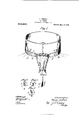
In the drawings wherein I have illustrated my invention, Figure 1 is a conventional illustration of a collar and tie showing, in dotted lines, the tie holder in connection therewith. Fig. 2 is a front or outside view of the device. Fig. 3 is an edge view. Fig. 4 is a sectional view on the line 4-4 of Fig. 2, looking leftward. Fig. 5 is a sectional view of the tie and collar showing the holder engaging both.
The device, as illustrated, consists of a.
piece of wire bent to form an inverted. U-shaped portion 1, the two legs of which carry the points to engage with the tie. One of said legs, indicated at 2, is bent upward substantially parallel to the plane 0 the portion 1 and forms an open space 3 to receive the lower edge of the collar. The leg 2, at a suitable point below the edge of the tie band, bends outward a slight distance from the collar, and then turns obliquely downward and backward (or forward), as indicated at 4, against the collar, and is pointed at its extremity, the point being raised slightly, or curving outward from the collar, so that the tie may be engaged thereon. The other leg of the portion 1 bends outward a slight distance from the collar and then turns upward against the outer side of the collar, as shownat 5, and is pointed at its extremity,
! the point being a slight distance from the altitude than the that the tie band collar and at a lower portion 1 is preferably flattened, as shown, and provided with a convex or raised surface 6 which binds with su'liicient force against the collar to prevent the collar from slipping.
In using the devices, one or more thereof are engaged on the lower edge of the collar at convenient )ositions by pushing the lower edge of the collar into the space 3, as shown. in Fig. 5. The tie may then be adjusted to )roper position without engaging with tlie points of the holder since the arched portions of the pointed legs hold the tie from catching on the points without manual assistance. After being adjusted to proper position the band of the tie is manually drawn downward and engaged on the pointed leg -l and then pushed upward. The operation is reversed in order to engage the tie on the leg 5, and, after adjustment, the tie will be held from raising by the legs 4, and from lowering by the legs 5, and from slipping by both of said legs. The method of detaching the tie is obvious.
It is probable that various other constructions of the device within the scope of the appended claims will suggest themselves to those familiar with this kind. of article. For this, and other obvious reasons, I do not restrict myself to specific details, but
What I claim and desire to secure by Letters Patent is- 1. A tie holding device comprising a back portion, a projection on said back portion adapted to bind against the collar, and a front portion composed of a leg extending upwardly against the outer side of the collar and cooperating with said back portion and said projection to bind the device on the collar and having a downwardly extending point, and a second leg extending upwardly from the lower edge of the collar and having a point at its extremity below the upper part of the first-named log, substantially as speciiied.
2. A tie holding device comprising a back portion adapted to bind against the inside of the collar, and a front portion composed of a pointed log extending upwardly am outwardly from the lower edge of the collar, and a second leg extending upwardly against thc The arch of the outer side of the eollar and eoo'Jerating with the bark portion. to bind the deviee on the l collar and having a downwardly extending point. substantially as speeified.
3. A tie holding device COHlPllSlIlg a back portion, and a. front portion forming a space to rereive the lower edge of the eollar, and J eoniposed, as to the 'l'ront portion, of an upwardly extending leg having a downwardly extending portion arranged to press against 1 the collar and a point projeeting obliquely l downward and outward from the point of I pressure, and a serond leg extending from the lower edge of the roller, substantially as specified. l
4. A tie holding device comprising a baek l portion and a front portion forming an intervening space to receive the lower edge of the 1 collar, and composed, as to the front portion, 1 of an upwardly extending leg having a down- 1 wardly extending portion arranged to press against the collar and a point projecting l obliquely downward and outward from the point of pressure, and a second leg curving l outwardly from the lower edge of the collar and then inwardly to press against the collar l and having a point projecting obliquely upward and outward from the point of pressure, substantially as specified.
5. A tie holding device comprising a wire bent to form an inverted U-shaped back por tion adapted to bind against the inside of the eollar, and a front portion eomposed of one of the ends of said wire extending upwardly Itl'Olll the lower edge of the eollar and provided with a point at its extremity and the other of said ends extending upwardly against the outer side of the collar to a greater altitude than the point of said firstnanied end and having a downwardly extending portion arranged to press against the collar and a point projecting obliquely downward and outward from the point of pressure, substantially as specified.
In testimony whereof, I hereto aflix my signature this 27th day of May, 1907, in the presence of two subscribing witnesses.
GEORGE BULLOCK.
Witnesses:
F. J. MCGASLIN, J. I). RIPPEY.
Priority Applications (1)
| Application Number | Priority Date | Filing Date | Title |
|---|---|---|---|
| US37925707A US915550A (en) | 1907-06-15 | 1907-06-15 | Tie-holder. |
Applications Claiming Priority (1)
| Application Number | Priority Date | Filing Date | Title |
|---|---|---|---|
| US37925707A US915550A (en) | 1907-06-15 | 1907-06-15 | Tie-holder. |
Publications (1)
| Publication Number | Publication Date |
|---|---|
| US915550A true US915550A (en) | 1909-03-16 |
Family
ID=2983986
Family Applications (1)
| Application Number | Title | Priority Date | Filing Date |
|---|---|---|---|
| US37925707A Expired - Lifetime US915550A (en) | 1907-06-15 | 1907-06-15 | Tie-holder. |
Country Status (1)
| Country | Link |
|---|---|
| US (1) | US915550A (en) |
-
1907
- 1907-06-15 US US37925707A patent/US915550A/en not_active Expired - Lifetime
Similar Documents
| Publication | Publication Date | Title |
|---|---|---|
| US915550A (en) | Tie-holder. | |
| US822984A (en) | Bottle-holder. | |
| US704139A (en) | Food-guard. | |
| US748367A (en) | Griddle-greaser. | |
| US758449A (en) | Clamp or stop-cock for flexible tubes. | |
| US303297A (en) | Chaeles f | |
| US1333515A (en) | Shelf-clamp | |
| US1098638A (en) | Shirt-front attachment. | |
| US254933A (en) | Stove-lifter | |
| US963747A (en) | Collar-fastener. | |
| US728427A (en) | Extinguisher for candles. | |
| US414857A (en) | Arthur w | |
| US1050948A (en) | Suspender-clasp. | |
| US1230519A (en) | Combined back collar-button and necktie-holder. | |
| US472343A (en) | Cuff-holder | |
| US1598087A (en) | Belt-retaining hook | |
| US303652A (en) | Marston and-fisher m | |
| US1255273A (en) | Package tie and handle. | |
| US295310A (en) | Clasp | |
| US1384812A (en) | Clasp | |
| US174082A (en) | Improvement in bale-ties | |
| US484962A (en) | Attaching window-shades to rollers | |
| US1106886A (en) | Garment-supporter. | |
| US483783A (en) | Scarf-clasp | |
| US363098A (en) | Edward tea |