US9109891B2 - Stereo camera - Google Patents
Stereo camera Download PDFInfo
- Publication number
- US9109891B2 US9109891B2 US13/574,952 US201113574952A US9109891B2 US 9109891 B2 US9109891 B2 US 9109891B2 US 201113574952 A US201113574952 A US 201113574952A US 9109891 B2 US9109891 B2 US 9109891B2
- Authority
- US
- United States
- Prior art keywords
- image
- images
- camera
- area
- distance information
- Prior art date
- Legal status (The legal status is an assumption and is not a legal conclusion. Google has not performed a legal analysis and makes no representation as to the accuracy of the status listed.)
- Expired - Fee Related, expires
Links
Images


Classifications
-
- G—PHYSICS
- G01—MEASURING; TESTING
- G01C—MEASURING DISTANCES, LEVELS OR BEARINGS; SURVEYING; NAVIGATION; GYROSCOPIC INSTRUMENTS; PHOTOGRAMMETRY OR VIDEOGRAMMETRY
- G01C11/00—Photogrammetry or videogrammetry, e.g. stereogrammetry; Photographic surveying
- G01C11/04—Interpretation of pictures
- G01C11/06—Interpretation of pictures by comparison of two or more pictures of the same area
-
- G—PHYSICS
- G03—PHOTOGRAPHY; CINEMATOGRAPHY; ANALOGOUS TECHNIQUES USING WAVES OTHER THAN OPTICAL WAVES; ELECTROGRAPHY; HOLOGRAPHY
- G03B—APPARATUS OR ARRANGEMENTS FOR TAKING PHOTOGRAPHS OR FOR PROJECTING OR VIEWING THEM; APPARATUS OR ARRANGEMENTS EMPLOYING ANALOGOUS TECHNIQUES USING WAVES OTHER THAN OPTICAL WAVES; ACCESSORIES THEREFOR
- G03B35/00—Stereoscopic photography
- G03B35/08—Stereoscopic photography by simultaneous recording
- G03B35/10—Stereoscopic photography by simultaneous recording having single camera with stereoscopic-base-defining system
-
- G06K9/00208—
-
- G06K9/209—
-
- G06T7/0075—
-
- G—PHYSICS
- G06—COMPUTING; CALCULATING OR COUNTING
- G06T—IMAGE DATA PROCESSING OR GENERATION, IN GENERAL
- G06T7/00—Image analysis
- G06T7/50—Depth or shape recovery
- G06T7/55—Depth or shape recovery from multiple images
- G06T7/593—Depth or shape recovery from multiple images from stereo images
-
- G—PHYSICS
- G06—COMPUTING; CALCULATING OR COUNTING
- G06V—IMAGE OR VIDEO RECOGNITION OR UNDERSTANDING
- G06V10/00—Arrangements for image or video recognition or understanding
- G06V10/10—Image acquisition
- G06V10/12—Details of acquisition arrangements; Constructional details thereof
- G06V10/14—Optical characteristics of the device performing the acquisition or on the illumination arrangements
- G06V10/147—Details of sensors, e.g. sensor lenses
-
- G—PHYSICS
- G06—COMPUTING; CALCULATING OR COUNTING
- G06V—IMAGE OR VIDEO RECOGNITION OR UNDERSTANDING
- G06V20/00—Scenes; Scene-specific elements
- G06V20/60—Type of objects
- G06V20/64—Three-dimensional objects
- G06V20/647—Three-dimensional objects by matching two-dimensional images to three-dimensional objects
-
- H04N13/0022—
-
- H04N13/0239—
-
- H04N13/025—
-
- H—ELECTRICITY
- H04—ELECTRIC COMMUNICATION TECHNIQUE
- H04N—PICTORIAL COMMUNICATION, e.g. TELEVISION
- H04N13/00—Stereoscopic video systems; Multi-view video systems; Details thereof
- H04N13/10—Processing, recording or transmission of stereoscopic or multi-view image signals
- H04N13/106—Processing image signals
- H04N13/128—Adjusting depth or disparity
-
- H—ELECTRICITY
- H04—ELECTRIC COMMUNICATION TECHNIQUE
- H04N—PICTORIAL COMMUNICATION, e.g. TELEVISION
- H04N13/00—Stereoscopic video systems; Multi-view video systems; Details thereof
- H04N13/20—Image signal generators
- H04N13/204—Image signal generators using stereoscopic image cameras
- H04N13/239—Image signal generators using stereoscopic image cameras using two 2D image sensors having a relative position equal to or related to the interocular distance
-
- H—ELECTRICITY
- H04—ELECTRIC COMMUNICATION TECHNIQUE
- H04N—PICTORIAL COMMUNICATION, e.g. TELEVISION
- H04N13/00—Stereoscopic video systems; Multi-view video systems; Details thereof
- H04N13/20—Image signal generators
- H04N13/204—Image signal generators using stereoscopic image cameras
- H04N13/25—Image signal generators using stereoscopic image cameras using two or more image sensors with different characteristics other than in their location or field of view, e.g. having different resolutions or colour pickup characteristics; using image signals from one sensor to control the characteristics of another sensor
-
- H—ELECTRICITY
- H04—ELECTRIC COMMUNICATION TECHNIQUE
- H04N—PICTORIAL COMMUNICATION, e.g. TELEVISION
- H04N13/00—Stereoscopic video systems; Multi-view video systems; Details thereof
- H04N2013/0074—Stereoscopic image analysis
- H04N2013/0081—Depth or disparity estimation from stereoscopic image signals
-
- H—ELECTRICITY
- H04—ELECTRIC COMMUNICATION TECHNIQUE
- H04N—PICTORIAL COMMUNICATION, e.g. TELEVISION
- H04N2213/00—Details of stereoscopic systems
- H04N2213/005—Aspects relating to the "3D+depth" image format
Definitions
- the present invention relates to a stereo camera, and particularly relates to a stereo camera provided with a pair of cameras having different camera parameters.
- a stereo camera provided with a pair of cameras is capable of generating a distance image including information of a distance to a photographic subject based on a parallax of images obtained by the both cameras, but in the stereo camera, the paired cameras are typically made up of cameras having the same camera parameters.
- Patent Document 1 discloses a configuration where a three-dimensional picture including distance information is picked up by horizontally arranged two lenses and a two-dimensional image is picked up by another lens different from the above, and discloses a configuration where a three-dimensional video picture is acquired within a certain range of a focal distance and a two-dimensional image is acquired in the case beyond that range, but the two lenses for a three-dimensional picture are constituted of lenses having the same characteristics.
- Patent Document 2 discloses a system to create an image for stereo viewing which is seen from an arbitrary view point based on images and distance information obtained by a stereo camera, and image processing for creating images for stereo viewing is performed on the assumption that two cameras constituting the stereo camera have the same camera parameters.
- the present invention was made for solving the problem as described above, and an object thereof is to provide a stereo camera capable of generating stereo view images from an arbitrary view point, while suppressing manufacturing cost.
- a first aspect of a stereo camera includes: a first imaging part which photographs a first image; a second imaging part which has camera parameters different from those of the first imaging part and photographs a second image; a distance information acquiring part which associates each pixel in the first and second images and acquires distance information including parallax information; and a right/left image generating part which generates a stereo view image based on one of the first and second images and the distance information.
- the distance information acquiring part decides a correspondence detection area where correspondence detection is performed, based on photographing information at the time of photographing the first and second images.
- the distance information acquiring part regards one of the first and second images as a template and performs template matching with the other, to decide an area with the highest degree of agreement as the correspondence detection area.
- the distance information acquiring part when the first and second images have different photographing magnifications, performs transformation of resolution processing on an image to become the template, so as to create the template.
- the distance information acquiring part extracts object candidate areas that become object candidates by object recognition with respect to the first and second images, and performs comparison among the obtained object candidate areas, to decide an area with the highest degree of agreement as the correspondence detection area.
- the distance information acquiring part sets an optical axial center of the other image on one image with respect to the first and second images, aligns the optical axial center of the other image set on the one image with the optical axial center of the other image, converts the one image to an image size fitted with an imaging device having photographed the other image and superimposes the images, to decide the correspondence detection area.
- the distance information acquiring part decides, with respect to the first and second images, the correspondence detection area at a ratio of vertical angles of view centered on the optical axial centers.
- the distance information acquiring part decides one-dimensional area along epipolar lines as the correspondence detection area with respect to the first and second images.
- the distance information acquiring part sets, with respect to the respective correspondence detection areas of the first and second images, a base position inside the area to be on the base side of correspondence detection to a position of a sub-pixel having a finer size than a pixel size, to perform correspondence detection.
- the distance information acquiring part regards an image having the correspondence detection area with a larger number of pixels as a base image, out of the respective correspondence detection areas of the first and second images, to perform correspondence detection.
- the distance information acquiring part when zoom photographing is performed at the time of photographing the first and second images, changes a sampling interval of corresponding points in accordance with a zooming degree.
- the distance information acquiring part decreases a sampling interval of corresponding points with increase in zoom magnification.
- the distance information acquiring part changes a sampling interval of corresponding points in accordance with the number of pixels of one with a smaller number of pixels out of the respective correspondence detection areas of the first and second images.
- the distance information acquiring part sets an aspect ratio of the window such that the aspect ratio on the object surface is isotropic, to perform correspondence detection.
- the first imaging part has a higher resolution than the second imaging part
- the right/left image generating part regards the first image as a main image, displaces an image in the correspondence detection area inside the second image in accordance with the parallax information, and regards the first image and the new second image as the right/left images.
- the right/left image generating part compensates pixel information from the first image.
- the first imaging part has a higher resolution than the second imaging part, and when the second image has a higher photographing magnification than the first image, the right/left image generating part embeds the second image into the first image to generate a new second image, and regards the first image and the new second image as the right/left images.
- the first imaging part has a higher resolution than the second imaging part, and when the first image has a higher photographing magnification than the second image, the right/left image generating part embeds the first image into the second image to generate a new first image, and regards the new first image and the second image as the right/left images.
- the first imaging part has a zoom function, and when the first image is a zoomed image, the right/left image generating part generates an image with a changed baseline length in accordance with a zoom magnification, to generate a new first image.
- the right/left image generating part when generating the new first image, changes an image size so as to hold a photographic subject within an image even with a change in base-line length.
- a lens of the second imaging part is a fovea lens.
- a lens of the second imaging part is an anamorphic lens.
- the first imaging part has a higher resolution than the second imaging part
- the stereo camera further includes a sensor which senses arrangement of the stereo camera with the first and second imaging part arrayed in a horizontally placed manner in parallel with a horizontal plane, and stops an operation of the distance information acquiring part in the case of sensing horizontal placement
- the right/left image generating part provides information of the first image to the second image to create a new second image, and regards the first image and the new second image as the right/left images.
- the stereo camera concerning the present invention, it is possible to obtain stereo view images even when the stereo camera is one having two imaging parts with different camera parameters, and hence it is possible to generate the stereo view images at low cost.
- the stereo camera concerning the present invention, it is possible to decide a correspondence detection area based on photographing information, such as zoom magnifications, at the time of photographing first and second images.
- the stereo camera concerning the present invention, it is possible to decide the correspondence detection by template matching.
- the fourth aspect of the stereo camera concerning the present invention even when the first and second images have different photographing magnifications, it is possible to decide the correspondence detection area by template matching.
- the stereo camera concerning the present invention, it is possible to decide the correspondence detection area by object recognition.
- the sixth aspect of the stereo camera concerning the present invention it is possible to decide with ease the correspondence detection area by use of optical axial centers.
- the seventh aspect of the stereo camera concerning the present invention it is possible to decide the correspondence detection area at the ratio of vertical angles of view centered on the optical axial centers of the first and second images.
- the eighth aspect of the stereo camera concerning the present invention it is possible to decide the correspondence detection area by means of one-dimensional areas along epipolar lines with respect to the first and second images.
- the ninth aspect of the stereo camera concerning the present invention since a base position inside the area to be on the base side of correspondence detection is set to a sub-pixel position to perform correspondence detection, even when a base image and a reference image have different magnifications, it is possible to make the sampling intervals uniform.
- the stereo camera concerning the present invention, it is possible to perform correspondence detection, regarding one with a larger number of pixels as the base image.
- the eleventh and twelfth aspects of the stereo camera concerning the present invention since a sampling interval of corresponding points is changed in accordance with a zooming degree, it is possible to reduce the time spent for correspondence detection in the case of no use of zooming.
- the thirteenth aspect of the stereo camera concerning the present invention since a sampling interval of corresponding points is changed in accordance with the number of pixels of one with a smaller number of pixels out of the correspondence detection areas, it is possible to deal with the case of the first image and the second image having different numbers of pixels due to zooming.
- an aspect ratio of the window is set such that the aspect ratio on the object surface is isotropic, to perform correspondence detection, whereby it is possible to prevent deterioration in accuracy of association in correspondence detection.
- the second image is a high-resolution image of the same level as the first image and both images are used as stereo view images, whereby it is possible to make a three-dimensional display free from incompatibility.
- the stereo camera concerning the present invention, it is possible to enhance accuracy of a stereo-viewable portion.
- a new first image with a base-line length changed in accordance with a zoom magnification is generated, whereby it is possible to make a three-dimensional display free from incompatibility.
- the lens of the second imaging part is made of a fovea lens, whereby it is possible to obtain an image with a large amount of information of the central part.
- the lens of the second imaging part is made of an anamorphic lens, whereby it is possible to obtain an image with a wide angle of view in one direction.
- the twenty-third aspect of the stereo camera concerning the present invention it is possible to obtain the stereo view images by simple processing.
- FIGS. 1 to 3 are views describing a usage pattern of a stereo camera according to the present invention.
- FIG. 4 is a view schematically showing a concept of generation of stereo view images.
- FIG. 5 is a diagram showing photographed images in the case of using the stereo camera in a horizontally placed manner.
- FIG. 6 is a view showing images obtained by the stereo camera.
- FIG. 7 is a block diagram showing a configuration of the stereo camera according to the present invention.
- FIG. 8 is a flowchart showing a process procedure from acquisition of an image to acquisition of distance information.
- FIG. 9 is as conceptual view describing setting processing for a correspondence detection area.
- FIG. 10 is a view describing a first method for deciding a correspondence detection area.
- FIG. 11 is a view describing a transformation of resolution processing.
- FIGS. 12 to 13 are views describing a second method for deciding a correspondence detection area.
- FIGS. 14 to 15 are views describing a fourth method for deciding a correspondence detection area.
- FIGS. 16 to 17 are views describing a fifth method for deciding a correspondence detection area.
- FIG. 18 is a view describing a sixth method for deciding a correspondence detection area.
- FIG. 19 is a conceptual view describing correspondence detection processing.
- FIG. 20 is a view describing a first method for correspondence detection.
- FIG. 21 is a view describing a second method for correspondence detection.
- FIGS. 22 to 23 are views describing a third method for correspondence detection.
- FIG. 24 is a view describing a three-dimensional reconstruction.
- FIG. 25 is a flowchart describing a procedure for generating right/left images.
- FIGS. 26 to 28 are views describing a first method for generating right/left images.
- FIGS. 29 to 30 are views describing a modified example of the first method for generating right/left images.
- FIG. 31 is a view describing a method for solving a problem at the time of generating a new first image.
- FIGS. 32 to 34 are views describing a second method for generating right/left images.
- FIG. 35 is a view describing Modified Example 1 of the second method for generating right/left images.
- FIG. 36 is a view describing Modified Example 2 of the second method for generating right/left images.
- FIG. 37 is a view describing a third method for generating right/left images.
- FIG. 38 is a diagram describing a fourth method for generating right/left images.
- FIGS. 39 to 40 are views describing the fourth method for generating right/left images.
- FIGS. 1 to 6 First, a summary of the present invention will be described using FIGS. 1 to 6 .
- FIGS. 1 to 3 are views describing usage patterns of a stereo camera according to the present invention.
- FIG. 1 shows an example of using a stereo camera VC 1 in a vertically placed manner
- FIG. 2 shows an example of using the stereo camera VC 1 in a horizontally placed manner.
- the stereo camera VC 1 takes a configuration where a main camera MC and a sub-camera SC are arranged apart from each other just by a base-line length L, and the main camera MC and the sub-camera SC are arrayed so as to be in parallel with one side of a camera case. It is to be noted that the main camera MC and the sub-camera SC can be referred to as an imaging part inside the stereo camera VC 1 .
- the main camera MC is a digital camera system having a so-called zoom lens with a high resolution and a variable focus, such as a lens compatible with high-definition TV broadcasting (HDTV lens) or the like.
- the sub-camera SC is a digital camera system with a low resolution and a single focus, such as a small-sized unit camera installed in a mobile phone or the like, or a micro camera unit (MCU). Note that as a lens for the sub-camera SC, the zoom lens may be used, but a high resolution is not required.
- a variable-power lens may be used such as a fovea lens (having a characteristic that an image at the rim is significantly compressed as compared with an image at the center), a fish-eye lens or an anamorphic lens.
- An image with a large amount of information at the central part is obtained by use of the fovea lens or the fish-eye lens, and an image with a wide angle of view in one direction is obtained by use of the anamorphic lens.
- a state where the stereo camera VC 1 is arranged such that the main camera MC and the sub-camera SC are arrayed vertically to a horizontal plane is referred to as vertical placement.
- a state where the stereo camera VC 1 is arranged such that the main camera MC and the sub-camera SC are arrayed parallelly to the horizontal plane is referred to as horizontal placement.
- a stereo camera VC 2 shown in FIG. 3 is the same as the stereo camera VC 1 in that the main camera MC and the sub-camera SC are arranged apart from each other just by a base-line length L, but the main camera MC and the sub-camera SC are arrayed so as to be diagonal to any side of the camera case.
- FIG. 3 shows a state where the arrangement is made such that the main camera MC and the sub-camera SC are arrayed as inclined from the verticality to the horizontal plane, and the state is referred to as vertical placement. A state rotated at 90 degrees with respect to this state is referred to as horizontal placement. It is to be noted that the arrangement may be made such that the cameras vertically or horizontally change places with respect to the arranged states as described above.
- the stereo camera according to the present invention can be vertically placed.
- An advantage of the vertical placement is that the camera has a vertically long structure similar to that of a conventional camcorder, and is configured to be compact and have the ease of operation free from incompatibility.
- FIG. 4 is a view schematically showing a concept of generation of stereo view images by means of the stereo camera VC 1 shown in FIG. 1 .
- Part ( a ) of FIG. 4 shows a high-resolution two-dimensional image obtained by the main camera MC
- part ( b ) of FIG. 4 shows a low-resolution two-dimensional image obtained by the sub-camera SC.
- the two cameras pick up images of the same photographic subject PS and background BG, images with different sizes of the photographic subject PS and different angles of view are obtained due to different magnifications of the lenses.
- Part ( c ) of FIG. 4 shows an image created from the images of part ( a ) and part ( b ) of FIG. 4
- part ( d ) of FIG. 4 shows an image obtained by the main camera MC.
- a three-dimensional display is made using such two images, and hence such two images are referred to as stereo view images. Using such stereo view images, a three-dimensional display is made on a display.
- the stereo camera VC 1 uses such stereo view images to perform a three-dimensional display on the display where the photographic subject PS is stereoscopically viewable, as shown in part ( e ) of FIG. 4 .
- FIG. 5 is a diagram showing photographed images in the case where the stereo camera VC 1 is used in the horizontally placed manner, as well as a schematic diagram of the photographic subject PS and the background BG seen from the above, where a vertical axis indicates distances to the photographic subject PS and the background BG, while a horizontal axis indicates a horizontal length in the case where an optical axis of the main camera MC is regarded as an original point and indicates horizontal angles of view in the case where photographing is performed by means of the main camera MC and the sub-camera SC.
- the main camera MC examples of photographing with three steps of magnification are shown, and an image photographed in the state of the lowest magnification (the widest angle of view) is referred to as a first main camera image, and its angle of view is indicated by a line L 1 .
- An image photographed in the state of the second highest magnification is referred to as a second main camera image, and its angle of view is indicated by a line L 2 .
- an image photographed in the state of the highest magnification (the narrowest angle of view) is referred to as a third main camera image, and its angle of view is indicated by a line L 3 .
- the sub-camera SC has no zoom function, thus having only one kind of angle of view, and that angle of view is indicated by a line L 4 .
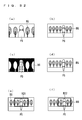
- FIG. 6 shows images obtained by the photographed images shown in FIG. 5 .
- Part ( a ) of FIG. 6 shows a first main camera image photographed by the main camera MC
- part ( b ) of FIG. 6 shows a second main camera image photographed by the main camera MC
- part ( c ) of FIG. 6 shows a third main camera image photographed by the main camera MC.
- part ( d ), part ( e ) and part ( f ) of FIG. 6 respectively show images obtained by the sub-camera SC at the time of acquiring the images of part ( a ) to part ( c ) of FIG. 6 .
- Any of the sub-camera images is an image with the same magnification. It is to be noted that, since an optical axis of the sub-camera SC is apart from the main camera MC just by the base-line length L, there is seen a difference, associated with a parallax, between the image obtained by the sub-camera SC and the image obtained by the main camera MC. Further, the main camera MC and the sub-camera SC are different from each other in magnification, and are also different in sizes of the photographic subject PS and the background BG.
- FIG. 7 is a block diagram showing the configuration of the stereo camera VC 1 .
- the main camera MC and the sub-camera SC arc connected to a photographing information acquiring part 1 , and photographing information is provided to the photographing information acquiring part 1 along with image data obtained by the respective cameras.
- one of image data of the images obtained by the main camera MC and the sub-camera SC is provided as a main image to a main image acquiring part 2 via the photographing information acquiring part 1 .
- image data obtained by the main camera MC and the sub-camera SC are provided to the distance information acquiring part 3 via the photographing information acquiring part 1 , to acquire distance information.
- known camera information is provided from a camera information accumulator 6 to the distance information acquiring part 3 for acquiring distance information.
- a main image outputted from the main image acquiring part 2 and distance information outputted from the distance information acquiring part 3 are provided to a right/left image generating part 4 , to generate stereo view images. Then, the obtained stereo view images (right/left images) are provided to a three-dimensional displaying part 5 , such as a liquid crystal screen, and then three-dimensionally displayed.
- photographing information is acquired at the time of acquiring the image as shown in FIG. 6 .
- the photographing information acquired at this time is a parameter such as a zoom magnification, a focal distance, an angle of view, which may vary at the time of photographing.
- a zoom magnification a parameter such as a zoom magnification, a focal distance, an angle of view, which may vary at the time of photographing.
- all the information of the zoom magnification, the focal distance and the angle of view is not necessary, and as long as any one of the information is obtained, the other information can be worked out by calculation.
- an angle of view ( ⁇ ) in each direction can be calculated by Mathematical Expression (1) below:
- photographing information is held as known camera information in the camera information accumulator 6 .
- FIG. 8 is a flowchart showing a process procedure from acquisition of an image to acquisition of distance information.
- first, a first image and a second image are respectively acquired in Steps S 1 and S 2 .
- the first image is regarded as an image obtained by the main camera MC and the second image is regarded as an image obtained by the sub-camera SC.
- Step S 3 camera information acquired at the time of photographing by each of the main camera MC and the sub-camera SC is acquired.
- This known camera information is acquired from the camera information accumulator 6 (step S 4 ).
- This known camera information includes fixed photographing information in the sub-camera SC, and information of a dimension of the light receiver such as a CCD sensor and pixel disposed intervals (pixel pitches).
- a correspondence detection area is set for performing correspondence detection with respect to the first and second images (Step S 5 ).
- Step S 6 correspondence detection processing for each pixel in the first and second images are performed. Then, distance information is calculated based on the associated pixel, to acquire distance information (Step S 7 ).
- FIG. 9 is a conceptual view describing setting processing for a correspondence detection area.
- Part ( a ) of FIG. 9 shows a first main camera image photographed by the main camera MC
- part ( b ) of FIG. 9 shows the second main camera image
- part ( c ) of FIG. 9 shows the third main camera image.
- part ( d ), part ( e ), and part ( f ) of FIG. 9 respectively show images obtained by the sub-camera SC at the time of acquiring the images of part ( a ) to part ( c ) of FIG. 9 .
- an area R 1 surrounded by a broken line is the correspondence detection area
- the whole of the sub-camera image shown in part ( d ) of FIG. 9 is an area corresponding to the area R 1 .
- an area R 2 surrounded by a broken line is the correspondence detection area
- the whole of the second main camera image shown in part ( b ) of FIG. 9 is an area corresponding to the area R 2 .
- an area R 3 surrounded by a broken line is the correspondence detection area
- the whole of the third main camera image shown in part ( c ) of FIG. 9 is an area corresponding to the area R 3 .
- processing for deciding the correspondence detection area is the setting processing for a correspondence detection area, and first to sixth methods described below can be adopted for decision of the correspondence detection area.
- the first method is to decide the area by template matching where transformation of resolution processing is performed on either the first image obtained by the main camera MC or the second image obtained by the sub-camera SC, to generate a plurality of template images. Then, pattern matching with the other image is performed, to decide an area with the highest degree of agreement as a correspondence detection area.
- FIG. 10 shows a conceptual diagram of the first method.
- Part ( a ), part ( b ) and part ( c ) of FIG. 10 show first, second and third template images G 11 , G 12 and G 13 , created by use of the first image and respectively having different resolutions, and part ( d ) of FIG. 10 shows a sub-camera image as a comparison object.
- FIG. 11 is a diagram showing a concept of the transformation of resolution processing where a first template image G 11 , a second template image G 12 and a third template image G 13 are hierarchically shown.
- the transformation of resolution processing is processing of lowering a resolution to reduce a large image where a template image is created using the first image when the first image is a zoomed image, and a template image is generated using the second image when the first image is a non-zoomed image.
- a magnification of the second image is higher than a magnification of the first non-zoomed image.
- the second template image G 12 shown in part ( b ) of FIG. 10 and the area R 1 of the sub-camera image of part ( d ) of FIG. 10 show examples determined as having the highest degree of agreement, and the area R 1 becomes the correspondence detection area.
- the technique for template matching is a known technique, description thereof will be omitted.
- the second method is to decide the area by performing object recognition on the first image obtained by the main camera MC and the second image obtained by the sub-camera SC.
- Object candidate areas in the first and second images are decided using, for example, pattern recognition, to specify the largest object area out of the object candidate areas, and a correspondence detection area is decided based on a size of the object area. It should be noted that the largest object area can be specified out of the object candidate areas by calculating a total number of pixels with respect to each object area within each image and performing comparison among the object areas.
- FIG. 12 is a view showing an object specified by object recognition where part ( a ) of FIG. 12 shows an image of the photographic subject PS in the first image obtained by the main camera MC, and part ( b ) of FIG. 12 shows an image of the photographic subject PS in the second image obtained by the sub-camera SC. Further, in the first image shown in part ( a ) of FIG. 12 , a width of the largest portion of the photographic subject PS is indicated as “a”, and widths of areas outside both side surfaces of the photographic subject PS are indicated as “c” and “d”. Moreover, in the second image shown in part ( b ) of FIG.
- a width of the largest portion of the photographic subject PS is indicated as “b”, and based on a ratio between this dimension and a dimension of the width a in the first image, the outer edges of the correspondence detection area, that is widths X and Y of the areas outside both side surfaces of the photographic subject PS, are decided.
- FIG. 13 is the correspondence detection area decided in such a manner. That is, part ( a ) of FIG. 13 shows the first image obtained by the main camera MC, part ( b ) of FIG. 13 shows the second image obtained by the sub-camera SC, and the area R 1 surrounded by a broken line in the second image is the correspondence detection area.
- the outer edge of the correspondence detection area can be decided only in a parallax direction in the foregoing method
- the examples shown in FIGS. 12 and 13 are examples in the case of using the stereo camera VC 1 in the horizontally placed manner, and in the case of using it in the horizontally placed manner, the horizontal outer edge of the correspondence detection area can be decided, but its vertical outer edge is defined by the outer edge of the image.
- the vertical outer edge of the correspondence detection area can be decided, but its horizontal outer edge is defined by the outer edge of the image.
- the third method is to decide the area by the template matching of the first method by use of an object area specified by the object recognition described in the second method as a template.
- this is the same as the first method in that the template image is created using the first image when the first image is a zoomed image and the template image is created using the second image when the first image is a non-zoomed image.
- the fourth method is to decide the correspondence detection area by converting the first image obtained by the main camera MC and the second image obtained by the sub-camera SC such that the other image agrees with an optical axial center of one image, thereafter converting one image to such an image size so as to fit with an imaging device of the camera having photographed the other image, and superimposing the images.
- FIG. 14 shows a conceptual diagram of the fourth method.
- Part ( a ) of FIG. 14 shows respective angles of view of the main camera MC and the sub-camera SC by lines LM and LS, and also shows a first image G 1 and a second image G 2 respectively acquired by the main camera MC and the sub-camera SC.
- an optical axial center shown in the second image G 2 represents an optical axial center OL of the first image.
- the optical axial center is indicated by a line in the figure for a descriptive purpose, it is actually a point.
- Part ( b ) of FIG. 14 shows a diagram where the optical axial center OL of the first image shown on the second image G 2 obtained by the sub-camera SC is aligned with the optical axial center of the first image G 1 obtained by the main camera MC.
- the method for obtaining the optical axial center OL of the first image on the second image G 2 is obtained by calibration. That is, where the optical axial center of the first image G 1 is placed on the second image G 2 is unambiguously decided by calibration in shipment of the product. Therefore, when there is information thereof, the optical axis center OL of the first image on the second image G 2 is obtained with ease.
- an epipolar line that will be described later using FIG. 18 can also be unambiguously decided.
- FIG. 15 shows a conceptual view of processing of aligning the optical axis center OL of the first image shown on the second image with the optical axial center of the first image G 1 , and thereafter converting one image to such an image size as to fit with an imaging device of the other image, and superimposing the images.
- Part ( a ) of FIG. 15 shows the first image G 1
- part ( b ) of FIG. 15 shows the image obtained by converting the second image G 2 to the image size fitted with the imaging device of the first image G 1
- the superimposed area obtained by superimposing both images is regarded as the correspondence detection area R 1 .
- the image is normalized after the conversion to the fitted size of the imaging device.
- the size of the imaging device is held as known camera information and the photographing angle of view is acquired as photographing information, an angle of view per pixel can be figured out. That is, it is possible to change the size of the second image obtained by the sub-camera SC to the size of the first image obtained by the main camera MC
- the image size of the second image obtained by the sub-camera SC is 1000 ⁇ 1000 (pixels) and the horizontal angle of view is 100 degrees (the vertical one is also the same)
- a pixel disposed interval (pixel pitch) of the imaging device is 0.1, photographing is performed up to the horizontal angle of view of 100 degrees by use of the imaging device of 100 ⁇ 100 (pixels).
- the image size of the first image obtained by the main camera MC is 1000 ⁇ 1000 (pixels) and the horizontal angle of view is 50 degrees (the vertical one is also the same)
- the pixel pitch of the imaging device is 0.2
- photographing is performed up to the horizontal angle of view of 50 degrees by use of the imaging device of 200 ⁇ 200 (pixels).
- the foregoing fourth method is an effective method in the case of using the stereo camera VC 1 in the horizontally placed manner.
- the fifth method is to decide the correspondence detection areas by limiting areas by ratios of the vertical angles of view with respect to the first image obtained by the main camera MC and the second image obtained by the sub-camera SC.
- FIG. 16 shows the respective vertical angles of view of the main camera MC and the sub-camera SC by the lines LM and LS.
- a ratio of a distance S 1 from the optical axial center OL to the line LM and a distance S 2 between the line LM and the line LS at a position relatively near the stereo camera VS 1 is the same as a ratio of a distance S 11 from the optical axial center OL to the line LM and a distance S 12 between the line LM and the line LS at a position relatively distant from the stereo camera VS 1 .
- the correspondence detection area is limited with respect to the first and second images through use of the fact that the ratio of the angle of view in accordance with the distance from the camera is the same in terms of the vertical angle of view.
- FIG. 17 is a conceptual diagram that limits an area with a ratio of the angle of view and part ( a ) of FIG. 17 shows a vertical position of the optical axial center OL with respect to the first image G 1 .
- a ratio of upper and lower portions is calculated with respect to the vertical position of the optical axial center OL, and a vertical area of the second image G 2 is limited so as to have the same ratio as the above ratio, thereby limiting the area R 1 shown in part ( b ) of FIG. 17 .
- This area R 1 becomes as the correspondence detection area.
- the vertical position of the optical axial center OL is unambiguously decided due to being the center of the vertical angle of view.
- the sixth method is to decide the correspondence detection area through use of an epipolar line. That is, when a feature point in one three-dimensional space is photographed by two cameras, that point, the centers of lenses of the two camera and projections of the feature point on two image planes (image planes) obtained by the respective cameras are present on one plane.
- This plane is referred to as an epipolar plane, and an intersection between the epipolar plane and each image is referred to as an epipolar line.
- a point at which the epipolar line is intersected is referred to as an epipole.
- a corresponding point is limited on an epipolar line on the other image even if an original feature point is not known. Accordingly, a corresponding point may be detected by performing one-dimensional detection along the epipolar line.
- FIG. 18 shows an epipolar plane EP defined by lens centers CL 1 and CL 2 of the two cameras and a feature point P, and two image planes IP 1 and IP 2 obtained by the respective cameras. Diagonal lines shown on the image planes IP 1 and IP 2 are epipolar lines EL, and two points shown on the epipolar line EL are epipoles.
- the one-dimensional area along the epipolar line is regarded as the correspondence detection area, whereby it is possible to limit the correspondence detection area as compared with the case of regarding a two-dimensional plane as the correspondence detection area, so as to promote the efficiency in correspondence detection.
- one with a larger number of pixels in the correspondence detection may be regarded as the main image, or one with a wider angle of view in the acquired image may be regarded as the main image.
- the point is obtained by making a detection for a point (corresponding point) on a reference image which corresponds to an arbitrary attention point on a base image.
- the reference image is an image corresponding to the base image.
- the base image in stereo images, out of a pair of images picked up at the same time, one is the base image and the other is the reference image.
- a temporally earlier image is the base image and a temporally later image is the reference image.
- a template is set with respect to an attention point on this base image, a window on the reference image which corresponds to this template is detected, to obtain the corresponding point from this detected window.
- FIG. 19 is a conceptual view describing correspondence detection processing.
- Part ( a ) of FIG. 19 shows the second image obtained by the sub-camera SC as the base image
- part ( b ) of FIG. 19 shows the first image obtained by the main camera MC as the reference image.
- the attention point is indicated by OP and the corresponding point is indicated by AP.
- the first method is to set a base position on the base image to a sub pixel having a smaller size than the pixel size, to obtain the corresponding point on the reference image which corresponds thereto.
- FIG. 20 is a view schematically showing an example of setting a sub pixel on the base image, and although this figure shows an example of horizontally dividing one pixel into three parts to set three sub-pixels, division of the pixel is not limited to this, and it can further be divided. It is thereby possible to make the sampling intervals uniform even in the case of the base image and the reference image having different magnifications.
- a template for detection is set which is almost the same as the window having hitherto been used for detecting the corresponding point.
- the corresponding point is detected by cutting out respective certain ranges of areas in the mutually corresponding images and taking a correlation value between the areas, and this area is referred to as a window.
- the window as this area is generated by units of pixels, and it is not that part of pixels are included in the window and the others are not included therein.
- a position of the gravity center is the attention point as a position on the sub-pixel level, and hence the area is not necessarily an area by units of pixels.
- FIG. 20 shows an example of setting a template for detection TP with the sub-pixel SP as the attention point placed at the center when the attention point is on the position of the sub-pixel level.
- Japanese Patent Application Laid-Open No. 2001-195597 discloses a method where, after calculation of a correlation value between images, correlation values among pixels are applied to a linear expression or a curved expression for interpolation from a positional relation of a position of the highest correlation value and correlation values of its vicinity, to estimate a peak position and a peak value of the correlation values.
- the second method is to compare the numbers of pixels inside the correspondence detection areas with respect to the first image obtained by the main camera MC and the second image obtained by the sub-camera SC, to regard the one with a larger number of pixels as the base image.
- FIG. 21 shows an example of regarding one with a larger number of pixels as the base image, as well as showing an example of being able to increase attention points OP due to the large number of pixels.
- the third method is to roughly set an interval for correspondence detection at the time of default, and change a sampling interval of the corresponding points so as to change the interval for correspondence detection in accordance with a zooming degree in the case of acquiring information that zoom photographing has been performed. This is because correspondence detection needs to be performed with smaller intervals when the magnification of the lens is increased by zooming and the correspondence detection area becomes smaller.
- Adopting such a method allows reduction in the time spent for correspondence detection in the case of not using zooming.
- the fourth method is to compare the numbers of pixels inside the correspondence detection areas with respect to the first image obtained by the main camera MC and the second image obtained by the sub-camera SC, to set the sampling interval in accordance with the one with a smaller number of pixels.
- Part ( a ) of FIG. 22 shows the second image obtained by the sub-camera SC, and part ( b ) of FIG. 22 shows the first image obtained by the main camera MC.
- the area R 1 surrounded by a broken line is the correspondence detection area, and it is the whole of the first image that corresponds to this.
- the zoomed first image has a larger number of pixels inside the correspondence detection area, while the second image has a smaller number of pixels inside the correspondence detection area. Thereat, as shown in FIG. 23 , the sampling interval is adjusted.
- Part ( a ) of FIG. 23 shows the correspondence detection area R 1 in an enlarged manner for comparison, and also shows each single pixel PX in a large scale.
- Part ( b ) of FIG. 23 shows the first image obtained by the main camera MC where a sampling point PP is not provided in each pixel, but is provided in every third pixel. It is to be noted that setting of the sampling point PP may be set based on information of a zoom magnification as camera information.
- variable-power lens such as a fovea lens, a fish-eye lens or an anamorphic lens
- an aspect ratio of the window may be set such that the aspect ratio of the object surface is isotropic, to perform correspondence detection. This can prevent deterioration in accuracy of association in correspondence detection.
- correlations value degrees of similarity of a plurality of windows set in the reference image corresponding to the base image is calculated, and it is determined whether or not the template and the window corresponds to each other based on the correlation value.
- an SAD Sum of Absolute Difference
- SSD Sum of Squared Difference
- NCC Normalize cross Correlation
- the SAD method is a method using a function for obtaining a total sum of absolute values of brightness values of the template and the window, and a correlation value of the template and each window is obtained using this function. Further, there is also a correlation value calculating method having robustness as compared with the above SAD method. Specifically, this method is a method for calculating a similarity from a frequency decomposition signal of an image pattern by means of a signal of only a phase component with an amplitude component suppressed. The use of this method can realize calculation of the correlation value having robustness which is resistant to influences of a difference in photographing condition between the right/left cameras in the stereo image, noise, and the like.
- FFT fast Fourier transform
- DFT discrete Fourier transform
- DCT discrete cosine transform
- wavelet transform wavelet transform
- Hadamard transform and the like.
- POC Phase-Only Correlation
- a template is set on the base image, and a window having the same size is set on the reference image. Then, a correlation value (POC value) between the template and each window is calculated, to obtain a window corresponding to the template from the correlation value.
- the template of the base image and the window of the reference image are respectively subjected to two-dimensional discrete Fourier transform, to be standardized, and then synthesized to be subjected to a two-dimensional inverse discrete Fourier transform. In this manner, the POC value as the correlation value is obtained. Further, since the POC value is discretely obtained with respect to each pixel inside the window, the correlation value with respect to each pixel can be obtained.
- the method is different from the foregoing SAD method and the like for obtaining the correlation value with respect to each window.
- the correlation value can be obtained with respect to each pixel inside the window, and hence it is possible to perform correspondence detection less vulnerable to a brightness change by use of phase information inside a set range of the window.
- the method is suitable for such a case as the base image and the reference image having different image sizes as in the present application.
- parallax information When parallax information is about a horizontal parallax, distance information can be calculated with ease, but when it is about a vertical parallax, it is necessary to change it to a horizontal parallax by a three-dimensional reconstruction. Hereinafter, this processing will be described using FIG. 24 .
- a three-dimensional position (X, Y, Z) is calculated by Mathematical Expressions (3) and (4) below: It is noted that this is a position where the object is projected on the imaging device CD of the camera C 1 on the basis of (x, y).
- Mathematical Expression (2) may be transformed to one like Mathematical Expression (5):
- the three-dimensional reconstruction and the parallelization processing are general techniques and, for example, described in “Study on extraction of movement trajectory of people in indoor mixed circumstance by means of stereo camera”, written by Kosuke Kondoh, Department of Information and Communication, Faculty of Science and Engineering at Waseda University, Graduation Thesis for 2005.
- FIG. 25 is a flowchart describing a procedure for generating right/left images in the right/left image generating part 4 .
- Step S 23 when the main image and the distance information are respectively inputted in Steps S 21 and S 22 , first, an object for image generation is decided in Step S 23 .
- Step S 24 right/left images are generated in Step S 24 .
- first to fourth methods described below can be adopted.
- the first method is to generate, from the second image obtained by the sub-camera SC, a new second image as high a definition as the first image based on distance information.
- FIG. 26 is a view conceptually showing the first method. Part ( a ) and part ( b ) of FIG. 26 respectively show the first image obtained by the main camera MC and the second image obtained by the sub-camera SC.
- the first image is regarded as the main image and distance information is acquired from the second image
- part ( c ) and part ( d ) of FIG. 26 respectively schematically show the main image and an area where the distance information has been obtained.
- the second image is displaced in accordance with a parallax value, to generate the new second image.
- attention is focused only on a stereoscopically viewable area (area where a corresponding point has been obtained and parallax information has been obtained), and the right/left images are configured only in that area. That is, as shown in part ( d ) of FIG. 26 , out of the second image, attention is focused only on the area where distance information (parallax information) has been obtained, and an image in that area is displaced in accordance with a parallax value.
- pixels are compensated from the corresponding first image, thereby to obtain the new second image having a resolution of the same level as that of the first image.
- Part ( e ) of FIG. 26 shows the first image and part ( f ) of FIG. 26 shows the new second image.
- a position of the photographic subject PS is displaced in accordance with the parallax value, and it is possible to obtain stereo view images from the first image and the new second image. It is to be noted that in this method, since the new second image with a high resolution is generated, it is possible to obtain a high-definition image.
- FIG. 27 is a view showing the first and second images in the case of not performing processing for obtaining stereo view images
- part ( a ) of FIG. 27 shows a first main camera image
- part ( b ) of FIG. 27 shows a second main camera image
- part ( c ) of FIG. 27 shows a third main camera image which were photographed by the main camera MC.
- These main camera images are images with different magnifications.
- part ( d ), part ( e ) and part ( f ) of FIG. 27 respectively show images obtained by the sub-camera SC at the time of acquiring the images of part ( a ) to part ( c ) of FIG. 27 .
- the first image and the second image are completely different images, and stereo view images cannot be obtained from both images.
- FIG. 28 shows the first and second images in the case of applying the first method in order to obtain stereo view images.
- Part ( a ) of FIG. 28 shows a first main camera image
- part ( b ) of FIG. 28 shows a second main camera image
- part ( c ) of FIG. 28 shows a third main camera image which were photographed by the main camera MC, and while these main camera images are images with different magnifications, the second images respectively corresponding to these are also images with different magnifications.
- part ( d ) to part ( f ) of FIG. 28 show new second images obtained by means of the foregoing first method, and the respective new second images are images including displacements corresponding to parallaxes with respect to the first images.
- the second image obtained by the sub-camera SC having a resolution and the like which are inherently inferior to those of the main camera MC becomes a high-resolution image of the same level as the first image and both images are used as stereo view images, whereby it is possible to make a three-dimensional display free from incompatibility.
- the above-described first method has been a method to configure stereo view images only in the stereoscopically viewable area
- a method to regard the second image as the main image and generate stereo view images only in an area covered by the first image may be adopted.
- FIG. 29 is a view showing the first and second images in the case of not performing the processing for obtaining stereo view images and part ( a ) of FIG. 29 shows a first main camera image, part ( b ) of FIG. 29 shows a second main camera image and part ( c ) of FIG. 29 shows a third main camera image which were photographed by the main camera MC.
- These main camera images are images with different magnifications.
- part ( d ), part ( e ) and part ( f ) of FIG. 29 respectively show images obtained by the sub-camera SC at the time of acquiring the images of part ( a ) to part ( c ) of FIG. 29 .
- the first image and the second image are completely different images, and stereo view images cannot be obtained from both images.
- FIG. 30 shows the first and second images in the case of applying the modified example of the first method in order to obtain stereo view images.
- Part ( a ) of FIG. 30 shows an image photographed by the main camera MC as the first image, and this is an image with the same angle of view as that of the second image photographed by the sub-camera SC as shown in part ( d ) of FIG. 29 . Therefore in this case, the subject PS is displaced in the second image shown in part ( d ) of FIG. 29 just by a parallax value, thereby to generate a new first image shown in part ( a ) of FIG. 30 .
- a portion shown as an area R 10 uses data of the second image shown in part ( d ) FIG. 29 .
- data of the first image shown in part ( b ) of FIG. 29 is used in a portion shown as an area R 11 , and data of the second image is used in an area other than that. Then, the photographic subject PS is displaced in the image shown in part ( e ) of FIG. 30 just by a parallax value, thereby to generate a new first image shown in part ( b ) of FIG. 30 .
- the second image is used as the main image, and when the first image has a wider angle of view (part ( a ) of FIG. 29 ), the stereo view image is an area the whole of which can be three dimensionally displayed as in part ( d ) of FIG. 30 , or an image where only a portion covered by the first image can be three-dimensionally displayed. For this reason, it is possible to enhance the accuracy of the three-dimensionally displayable area.
- image information placed on the opposite side to the direction in which the area R 11 is displaced may be copied like a mirror, to obtain a perfect photographic subject PS as shown in part ( b ) of FIG. 31 .
- image information of a peripheral image PH placed further next thereto may be copied like a mirror. It is to be noted that, although image information may be moved in place of being copied, in that case, after movement of the peripheral image PH, a blank space is filled by performing such processing as to blur the image.
- the whole of the photographic subject PS is recognized as the object and processed so as to be included in the area R 11 as shown in part ( c ) of FIG. 31 , thereby allowing prevention of a part of the photographic subject PS from being separated off.
- the image PSX when the image PSX of the photographic subject PS not included in the area R 11 is separated off, the image PSX may be deleted.
- image information placed on the opposite side to the direction in which the area R 11 is displaced may be copied like a mirror, or the image information may be moved.
- the second method is to regard one image with a wider angle of view as the main image out of the first image obtained by the main camera MC and the second image obtained by the sub-camera SC, and embed only a stereoscopically viewable area into the main image.
- FIG. 32 is a view conceptually showing the second method. Part ( a ) and part ( b ) of FIG. 32 respectively show the first image obtained by the main camera MC and the second image obtained by the sub-camera SC.
- the second image with a wider angle of view is regarded as the main image and distance information is acquired from the first image
- part ( d ) of FIG. 32 schematically shows the main image
- part ( c ) of FIG. 32 schematically shows an area where distance information has been obtained.
- Embedding the first image into the second image generates a new first image.
- Part ( e ) of FIG. 32 shows the new first image as thus obtained.
- An area shown by an area R 21 in part ( e ) of FIG. 32 is an area embedded with the first image shown in part ( c ) of FIG. 32 which corresponds to the image where the distance information has been obtained.
- FIG. 33 is a view showing the first and second images in the case of not performing the processing for obtaining stereo view images
- part ( a ) of FIG. 33 shows a first main camera image
- part ( b ) of FIG. 33 shows a second main camera image
- part ( c ) of FIG. 33 shows a third main camera image which were photographed by the main camera MC.
- These main camera images are images with different magnifications.
- part ( d ), part ( e ) and part ( f ) of FIG. 33 respectively show images obtained by the sub-camera SC at the time of acquiring the images of part ( a ) to part ( c ) of FIG. 33 .
- the first image and the second image are completely different images, and stereo view images cannot be obtained from both images.
- FIG. 34 shows the first and second images in the case of applying the second method in order to obtain stereo view images.
- Part ( a ) of FIG. 34 shows an image photographed by the main camera MC as the first image, and this is an image with a wider angle of view than that of the second image photographed by the sub-camera SC as shown in part ( d ) of FIG. 33 . Therefore, in this case, the first image is regarded as the main image and the second image is embedded into the first image, to generate a new second image shown in part ( d ) of FIG. 34 .
- an area R 23 is the area embedded with the second image photographed by the sub-camera SC as shown in part ( d ) of FIG. 33 , and a portion other than the area R 23 is the area of the first image as the main image. In this case, the area R 23 corresponds to the area where distance information has been obtained.
- the second image photographed by the sub-camera SC as shown in part ( e ) of FIG. 33 has a wider angle of view than the first image photographed by the main camera MC as shown in part ( b ) of FIG. 33 , in this case, the second image is regarded as the main image and the first image is embedded into the second image, to generate a new first image shown in part ( b ) of FIG. 34 .
- an area R 24 is the area embedded with the first image photographed by the main camera MC as shown in part ( b ) of FIG. 33
- a portion other than the area R 24 is the area of the second image as the main image.
- the area R 24 corresponds to the area where distance information has been obtained.
- the second image photographed by the sub-camera SC shown in part ( f ) of FIG. 33 has a wider angle of view than the first image photographed by the main camera MC as shown in part ( c ) of FIG. 33 , in this case, the second image is regarded as the main image and the first image is embedded into the second image, to generate a new first image shown in part ( c ) of FIG. 34 .
- an area R 25 is the area embedded with the first image photographed by the main camera MC as shown in part ( c ) of FIG. 33
- a portion other than the area R 25 is the area of the second image as the main image.
- the area R 25 corresponds to the area where distance information has been obtained.
- the above-described second method has been a method to regard one with a wider angle of view as the main image out of the first image obtained by the main camera MC and the second image obtained by the sub-camera SC and embed only the stereoscopically viewable area into the main image
- a method for generating an image such that only the stereoscopically viewable area is configured as a three-dimensional image, and an area other than that displays pseudo three-dimensional data.
- FIG. 35 is a view conceptually showing Modified Example 1 of the second method. Part ( a ) and ( b ) of FIG. 35 respectively show the first image obtained by the main camera MC and the second image obtained by the sub-camera SC.
- the second image with a wider angle of view is regarded as the main image and distance information is acquired from the first image
- part ( d ) of FIG. 35 schematically shows the main image
- part ( c ) of FIG. 35 schematically shows an area where distance information has been obtained.
- Embedding the first image into the second image generates a new first image.
- Part ( e ) of FIG. 35 shows the new first image as thus obtained.
- An area shown by an area R 31 in part ( e ) of FIG. 35 is the area embedded with the first image.
- part ( f ) of FIG. 35 an area where distance information has not been obtained is filled in and schematically shown. As thus described, in part ( e ) of FIG. 35 , since distance information has not been obtained in an area other than the area indicated by the area R 31 , that portion may be displayed as the pseudo three-dimensional area.
- the area shown in R 32 like the second image shown in part ( f ) of FIG. 35 becomes a stereo-viewable area. It is to be noted that, since the area other than the area where distance information has actually been calculated has parallax information, in the case of generating stereo view images, it is necessary to displace the area other than the area where distance information has actually been calculated.
- the image inside the area R 31 is displaced just by a parallax and an area other than the area R 31 is also displaced just by the parallax.
- the area is displaced in a left direction in the figure. This results in the presence of an area NR without effective data on the right end of the figure.
- an image is generated such that only the stereoscopically viewable area is configured as the three-dimensional image and an area other than that displays the pseudo three-dimensional image, thereby allowing expansion of the stereoscopically viewable area.
- creation of pseudo three-dimensional data is disclosed, for example, in Japanese Patent Application Laid-Open No. 2005-151534.
- the document discloses a method for creating depth presumption data from a two-dimensional image not provided with distance information, to generate a pseudo three-dimensional image by use of this depth presumption data, and discloses creation of depth presumption data by use of a plurality of fundamental depth models showing depth values with respect to a plurality of scenes as fundamentals.
- the obtained distance information may be used for deciding an appropriate one out of the plurality of fundamental depth models (curved surface models) for generating the pseudo three-dimensional image.
- the above-described second method has been a method to regard one with a wider angle of view as the main image out of the first image obtained by the main camera MC and the second image obtained by the sub-camera SC and embed the area where distance information has actually been acquired into the main image as the stereoscopically viewable area, there may be formed a configuration to provide pseudo parallax information to an area other than the area where distance information has actually been acquired.
- FIG. 36 is a view conceptually showing Modified Example 2 of the second method.
- FIG. 36 shows the first and second images in the case of applying Modified Example 2 of the second method in order to obtain stereo view images.
- Part ( a ) of FIG. 36 shows an image photographed by the main camera MC as the first image, and this is an image with a wider angle of view than that of the second image photographed by the sub-camera SC as shown in part ( d ) of FIG. 33 . Therefore, in this case, the first image is regarded as the main image and the second image is embedded into the first image, to generate a new second image shown in part ( d ) of FIG. 36 .
- the area R 23 is the area embedded with the second image photographed by the sub-camera SC as shown in part ( d ) of FIG.
- a portion other than the area R 23 is the area of the first image which is provided with pseudo parallax information.
- the area R 23 is the area where distance information has actually been obtained, and the area other than this also has pseudo parallax information, resulting in that a portion shown by an area R 231 is the stereo viewable area.
- the second image photographed by the sub-camera SC as shown in part ( e ) of FIG. 33 has a wider angle of view than the first image photographed by the main camera MC as shown in part ( b ) of FIG. 33
- the second image is regarded as the main image and the first image is embedded into the second image, to generate a new first image shown in part ( b ) of FIG. 36 .
- the area R 24 is the area embedded with the first image photographed by the main camera MC as shown in part ( b ) of FIG. 33
- a portion other than the area R 24 is the area of the first image which is provided with pseudo parallax information.
- the area R 24 is the area where distance information has actually been obtained, and the area other than this also has pseudo parallax information, resulting in that a portion shown by an area R 241 is the stereo viewable area.
- the second image photographed by the sub-camera SC as shown in part ( f ) of FIG. 33 has a wider angle of view than the first image photographed by the main camera MC as shown in part ( c ) of FIG. 33
- the second image is regarded as the main image and the first image is embedded into the second image, to generate a new first image shown in part ( c ) of FIG. 36 .
- the area R 25 is the area embedded with the first image photographed by the main camera MC as shown in part ( c ) of FIG. 33
- a portion other than the area R 25 is the area of the first image which is provided with pseudo parallax information.
- the area R 25 is the area where distance information has actually been obtained, and the area other than this also has pseudo parallax information, resulting in that a portion shown by an area R 251 is the stereo viewable area.
- the pseudo parallax information may be provided as a fluctuation value that varies depending on the distance (the longer the distance, the smaller the provided parallax), or may be provided as a uniform fixed value regardless of the distance.
- the fixed value providing a parallax value of such an object as to be placed ahead of a photographic subject generates an image with incompatibility when it is three-dimensionally displayed, and hence it is desirable to make the parallax value as small as possible.
- the image inside the area R 23 is displaced just by the parallax and the area other than the area R 23 is also displaced just by the parallax.
- the area is displaced in a right direction in the figure. This results in the presence of an area NR without effective data on the left end of the figure.
- part ( c ) of FIG. 36 the area is displaced in the left direction in the figure. This results in the presence of an area NR without effective data on the right end of the figure.
- the third method is to create pseudo three-dimensional data by use of acquired distance information as auxiliary data.
- FIG. 37 is a view conceptually showing the third method. Part ( a ) and part ( b ) of FIG. 37 respectively show the first image obtained by the main camera MC and the second image obtained by the sub-camera SC.
- the second image with a wider angle of view is regarded as the main image and distance information is acquired from the first image, and part ( c ) of FIG. 37 schematically shows the area where distance information has been obtained.
- Part ( d ) of FIG. 37 schematically shows a new second image obtained by use of pseudo three-dimensional data created using this distance information as auxiliary data.
- the use of the first image and the new second image made up of this pseudo three-dimensional data can generate a stereo-viewable image.
- Japanese Patent Application Laid-Open No. 2005-151534 described above discloses a technique of previously preparing a depth model showing a depth value and creating depth presumption data by use of the model, adopting a method for creating pseudo three-dimensional data by use of acquired distance information as auxiliary data eliminates the need for previously preparing the depth model.
- the fourth method is to regard images as the right/left images for stereo viewing, the images being obtained by changing the base-line lengths in accordance with a zoom magnifications.
- FIG. 38 is a diagram showing photographed images in the case of using the stereo camera VC 1 in the horizontally placed manner, as well as a schematic diagram of the photographic subject PS and the background BG seen from the above, and a vertical axis indicates distances to the photographic subject PS and the background BG and a horizontal axis indicates horizontal lengths in the case where an optical axis of the main camera MC is regarded as an original point, and a horizontal angle of view in the case of photographing by means of the main camera MC and the sub-camera SC.
- zoom photographing is considered as being equivalent to changing a position of the stereo camera VC 1 and performing photographing, and there are schematically shown examples of variously changing the position of the stereo camera VC 1 with respect to the photographic subject PS.
- the photographic subject when the base-line length is changed, the photographic subject may be placed out of the angle of view depending on the zoom magnification. In that case, a generated image size may be made larger.
- FIG. 39 shows images obtained by the photographed images shown in FIG. 38 .
- Part ( a ) of FIG. 39 shows a main camera image photographed by the main camera MC
- part ( b ) of FIG. 39 shows an image obtained by the sub-camera SC at the time of acquiring the main camera image of part ( a ) of FIG. 39 .
- images part ( c ) and part ( d ) of FIG. 39 show images obtained by changing the base-line length.
- Part ( c ) of FIG. 39 shows an image obtained by the main camera MC in the case of not changing the base-line length
- part ( d ) of FIG. 39 shows the first image obtained by the main camera MC in the case of lengthening the base-line length.
- the photographic subject PS may be placed out of the angle of view by lengthening the base-line length, but in that case, as shown in part ( e ) of FIG. 39 , there is performed processing of creating an image of a portion lying off the angle of view in part ( d ) of FIG. 39 and also enlarging an image size so as to hold the photographic subject PS within the angle of view as shown in part ( e ) of FIG. 39 .
- the image of the portion lying off the angle of view may be created based on the image obtained by the main camera MC when the base-line length remains unchanged.
- the image shown in part ( c ) of FIG. 39 and the image shown in part ( e ) of FIG. 39 are used as stereo view images, since the image size of the image of part ( e ) of FIG. 39 is wide, the right/left images have different image sizes. Thereat, when the image as shown in part ( e ) of FIG. 39 is created, a certain image is also added to the image shown in part ( c ) of FIG. 39 so as to increase the image size.
- a method for adding the image there can be adopted a method for adding an area NR without effective data or a method for copying an image at the end like a mirror.
- first to fourth methods may be singly used or may be used in combination.
- combining the first method with the fourth method allows a three-dimensional display free from incompatibility.
- stereo view images may be generated without using distance information.
- the stereo camera VC 1 may be used in the horizontally placed manner as shown in FIG. 40( a ), and stereo view images may be generated using obtained first and second images.
- Part ( b ) and part ( c ) of FIG. 40 respectively show the first image obtained by the main camera MC and the second image obtained by the sub-camera SC, and part ( d ) of FIG. 40 shows a new second image with a high resolution obtained from both images.
- information of the high-resolution first image is provided to the low-resolution second image, to enhance the resolution of the second image, thereby creating a new second image, and the use of the first image and the new second image as stereo view images enables a three-dimensional display.
- the stereo camera VC 1 may have a sensor for sensing a vertically placed state and a horizontally placed state, and it may be configured such that in the case of the horizontally placed state, a circuit connection is changed so as to form a system to generate stereo view images without using distance information. It is to be noted that the above sensor and circuit connection change are controlled by a controller, such as a microcomputer, not shown in FIG. 7 .
- the camera may have such a function as to compare a picture obtained by the main camera MC and a picture obtained by the sub-camera SC, to detect a similarity of both images and issue an alarm when there is no similarity.
- detection may be performed simply by a difference in brightness of the image. This is because the picture obtained by the sub-camera SC is dark when the sub-camera SC is hidden by the hand.
- estimation may be performed using the pseudo three-dimensional image technique or interpolation may be performed from previous and subsequent images in a time series.
Landscapes
- Engineering & Computer Science (AREA)
- General Physics & Mathematics (AREA)
- Physics & Mathematics (AREA)
- Multimedia (AREA)
- Signal Processing (AREA)
- Theoretical Computer Science (AREA)
- Radar, Positioning & Navigation (AREA)
- Remote Sensing (AREA)
- Vascular Medicine (AREA)
- General Health & Medical Sciences (AREA)
- Health & Medical Sciences (AREA)
- Computer Vision & Pattern Recognition (AREA)
- Testing, Inspecting, Measuring Of Stereoscopic Televisions And Televisions (AREA)
- Studio Devices (AREA)
- Stereoscopic And Panoramic Photography (AREA)
- Cameras In General (AREA)
- Image Processing (AREA)
Applications Claiming Priority (3)
| Application Number | Priority Date | Filing Date | Title |
|---|---|---|---|
| JP2010021152 | 2010-02-02 | ||
| JP2010-021152 | 2010-02-02 | ||
| PCT/JP2011/050319 WO2011096251A1 (ja) | 2010-02-02 | 2011-01-12 | ステレオカメラ |
Publications (2)
| Publication Number | Publication Date |
|---|---|
| US20120293633A1 US20120293633A1 (en) | 2012-11-22 |
| US9109891B2 true US9109891B2 (en) | 2015-08-18 |
Family
ID=44355261
Family Applications (1)
| Application Number | Title | Priority Date | Filing Date |
|---|---|---|---|
| US13/574,952 Expired - Fee Related US9109891B2 (en) | 2010-02-02 | 2011-01-12 | Stereo camera |
Country Status (4)
| Country | Link |
|---|---|
| US (1) | US9109891B2 (ja) |
| EP (1) | EP2533541A4 (ja) |
| JP (1) | JP5472328B2 (ja) |
| WO (1) | WO2011096251A1 (ja) |
Cited By (4)
| Publication number | Priority date | Publication date | Assignee | Title |
|---|---|---|---|---|
| US20150256737A1 (en) * | 2014-03-05 | 2015-09-10 | Canon Kabushiki Kaisha | Image pickup apparatus capable of performing autofocus control in response to output of image pickup device, control method therefor, and storage medium storing control program therefor |
| US20180241923A1 (en) * | 2015-08-26 | 2018-08-23 | Zhejiang Dahua Technology Co., Ltd. | Methods and systems for traffic monitoring |
| US20180268531A1 (en) * | 2015-10-02 | 2018-09-20 | Sony Semiconductor Solutions Corporation | Image processing device, image processing method, and program |
| US20190325599A1 (en) * | 2018-04-22 | 2019-10-24 | Yosef Segman | Bmi, body and other object measurements from camera view display |
Families Citing this family (41)
| Publication number | Priority date | Publication date | Assignee | Title |
|---|---|---|---|---|
| US9736368B2 (en) | 2013-03-15 | 2017-08-15 | Spatial Cam Llc | Camera in a headframe for object tracking |
| US11119396B1 (en) | 2008-05-19 | 2021-09-14 | Spatial Cam Llc | Camera system with a plurality of image sensors |
| US10896327B1 (en) | 2013-03-15 | 2021-01-19 | Spatial Cam Llc | Device with a camera for locating hidden object |
| US10585344B1 (en) | 2008-05-19 | 2020-03-10 | Spatial Cam Llc | Camera system with a plurality of image sensors |
| US10354407B2 (en) | 2013-03-15 | 2019-07-16 | Spatial Cam Llc | Camera for locating hidden objects |
| US9171221B2 (en) | 2010-07-18 | 2015-10-27 | Spatial Cam Llc | Camera to track an object |
| JP5398750B2 (ja) * | 2011-01-26 | 2014-01-29 | 株式会社東芝 | カメラモジュール |
| JPWO2013038833A1 (ja) * | 2011-09-16 | 2015-03-26 | コニカミノルタ株式会社 | 画像処理システム、画像処理方法および画像処理プログラム |
| WO2013099169A1 (ja) | 2011-12-27 | 2013-07-04 | パナソニック株式会社 | ステレオ撮影装置 |
| US9142010B2 (en) * | 2012-01-04 | 2015-09-22 | Audience, Inc. | Image enhancement based on combining images from multiple cameras |
| US8619148B1 (en) | 2012-01-04 | 2013-12-31 | Audience, Inc. | Image correction after combining images from multiple cameras |
| CN104054109A (zh) * | 2012-01-17 | 2014-09-17 | 柯尼卡美能达株式会社 | 图像处理装置、图像处理方法以及图像处理程序 |
| JP5773944B2 (ja) * | 2012-05-22 | 2015-09-02 | 株式会社ソニー・コンピュータエンタテインメント | 情報処理装置および情報処理方法 |
| DE102012014994B4 (de) * | 2012-07-28 | 2024-02-22 | Volkswagen Aktiengesellschaft | Bildverarbeitungsverfahren für eine digitale Stereokameraanordnung |
| US9142019B2 (en) * | 2013-02-28 | 2015-09-22 | Google Technology Holdings LLC | System for 2D/3D spatial feature processing |
| WO2014141654A1 (ja) * | 2013-03-13 | 2014-09-18 | パナソニック株式会社 | 測距装置、撮像装置および測距方法 |
| US20150145950A1 (en) * | 2013-03-27 | 2015-05-28 | Bae Systems Information And Electronic Systems Integration Inc. | Multi field-of-view multi sensor electro-optical fusion-zoom camera |
| US9646384B2 (en) | 2013-09-11 | 2017-05-09 | Google Technology Holdings LLC | 3D feature descriptors with camera pose information |
| TWI508526B (zh) * | 2013-10-01 | 2015-11-11 | Wistron Corp | 產生視角平移影像之方法及其可攜式電子設備 |
| JP6668594B2 (ja) | 2014-02-25 | 2020-03-18 | 株式会社リコー | 視差演算システム、情報処理装置、情報処理方法及びプログラム |
| KR102221036B1 (ko) * | 2014-09-15 | 2021-02-26 | 엘지전자 주식회사 | 이동단말기 및 그 제어방법 |
| JP6424362B2 (ja) * | 2014-09-26 | 2018-11-21 | 株式会社明電舎 | 線条計測装置及びその方法 |
| JP6346868B2 (ja) * | 2015-03-31 | 2018-06-20 | 公益財団法人鉄道総合技術研究所 | ステレオ画像処理方法およびその装置 |
| GB2541101A (en) * | 2015-06-23 | 2017-02-08 | Bosch Gmbh Robert | Method and camera system for determining the distance of objects in relation to a vehicle |
| JP6552315B2 (ja) * | 2015-07-27 | 2019-07-31 | キヤノン株式会社 | 撮像装置 |
| JP6648916B2 (ja) * | 2015-07-27 | 2020-02-14 | キヤノン株式会社 | 撮像装置 |
| KR102482067B1 (ko) * | 2015-11-27 | 2022-12-28 | 삼성전자주식회사 | 전자 장치 및 그의 동작 방법 |
| JP6702796B2 (ja) * | 2016-05-16 | 2020-06-03 | キヤノン株式会社 | 画像処理装置、撮像装置、画像処理方法および画像処理プログラム |
| JP7159057B2 (ja) * | 2017-02-10 | 2022-10-24 | パナソニック インテレクチュアル プロパティ コーポレーション オブ アメリカ | 自由視点映像生成方法及び自由視点映像生成システム |
| KR20190013224A (ko) * | 2017-08-01 | 2019-02-11 | 엘지전자 주식회사 | 이동 단말기 |
| EP3486606A1 (de) * | 2017-11-20 | 2019-05-22 | Leica Geosystems AG | Stereokamera und stereophotogrammetrisches verfahren |
| US10721419B2 (en) * | 2017-11-30 | 2020-07-21 | International Business Machines Corporation | Ortho-selfie distortion correction using multiple image sensors to synthesize a virtual image |
| WO2020017377A1 (ja) | 2018-07-18 | 2020-01-23 | ミツミ電機株式会社 | 測距カメラ |
| US10452959B1 (en) * | 2018-07-20 | 2019-10-22 | Synapse Tehnology Corporation | Multi-perspective detection of objects |
| JP7150508B2 (ja) * | 2018-07-24 | 2022-10-11 | 株式会社東芝 | 鉄道車両用撮像システム |
| JP7132501B2 (ja) * | 2018-11-01 | 2022-09-07 | ミツミ電機株式会社 | 測距カメラ |
| JP2020136958A (ja) * | 2019-02-21 | 2020-08-31 | ソニーセミコンダクタソリューションズ株式会社 | イベント信号検出センサ及び制御方法 |
| US11010605B2 (en) | 2019-07-30 | 2021-05-18 | Rapiscan Laboratories, Inc. | Multi-model detection of objects |
| JP2022088142A (ja) | 2020-12-02 | 2022-06-14 | ヤマハ発動機株式会社 | 距離認識システムおよびその制御方法、船舶 |
| JP2023006232A (ja) * | 2021-06-30 | 2023-01-18 | 日立Astemo株式会社 | 距離測定装置 |
| WO2024004190A1 (ja) * | 2022-06-30 | 2024-01-04 | 富士通株式会社 | 3次元位置算出方法、装置、及びプログラム |
Citations (13)
| Publication number | Priority date | Publication date | Assignee | Title |
|---|---|---|---|---|
| JPH10134187A (ja) | 1996-10-31 | 1998-05-22 | Nec Corp | 三次元構造推定装置 |
| JP2000102040A (ja) | 1998-09-28 | 2000-04-07 | Olympus Optical Co Ltd | 電子ステレオカメラ |
| JP2001346226A (ja) | 2000-06-02 | 2001-12-14 | Canon Inc | 画像処理装置、立体写真プリントシステム、画像処理方法、立体写真プリント方法、及び処理プログラムを記録した媒体 |
| US20020041704A1 (en) * | 2000-08-24 | 2002-04-11 | Asahi Kogaku Kogyo Kabushiki Kaisha | Three-dimensional image capturing device |
| EP1418766A2 (en) | 1998-08-28 | 2004-05-12 | Imax Corporation | Method and apparatus for processing images |
| JP2004297540A (ja) | 2003-03-27 | 2004-10-21 | Sharp Corp | 立体映像記録再生装置 |
| US6915008B2 (en) * | 2001-03-08 | 2005-07-05 | Point Grey Research Inc. | Method and apparatus for multi-nodal, three-dimensional imaging |
| JP2005210217A (ja) | 2004-01-20 | 2005-08-04 | Olympus Corp | ステレオカメラ |
| JP2006093859A (ja) | 2004-09-21 | 2006-04-06 | Olympus Corp | 2眼撮像系を搭載したカメラ及びステレオ撮影可能なカメラ |
| WO2008002271A1 (en) | 2006-06-28 | 2008-01-03 | Hewlett-Packard Development Company, L.P. | Method for fast stereo matching of images |
| JP2008042227A (ja) | 2006-08-01 | 2008-02-21 | Hitachi Ltd | 撮像装置 |
| JP2008092007A (ja) | 2006-09-29 | 2008-04-17 | Fujifilm Corp | 撮影装置 |
| JP2009124308A (ja) | 2007-11-13 | 2009-06-04 | Tokyo Denki Univ | 多眼視画像作成システム及び多眼視画像作成方法 |
-
2011
- 2011-01-12 WO PCT/JP2011/050319 patent/WO2011096251A1/ja active Application Filing
- 2011-01-12 EP EP11739600.2A patent/EP2533541A4/en not_active Ceased
- 2011-01-12 US US13/574,952 patent/US9109891B2/en not_active Expired - Fee Related
- 2011-01-12 JP JP2011552721A patent/JP5472328B2/ja not_active Expired - Fee Related
Patent Citations (15)
| Publication number | Priority date | Publication date | Assignee | Title |
|---|---|---|---|---|
| JPH10134187A (ja) | 1996-10-31 | 1998-05-22 | Nec Corp | 三次元構造推定装置 |
| US6847392B1 (en) * | 1996-10-31 | 2005-01-25 | Nec Corporation | Three-dimensional structure estimation apparatus |
| EP1418766A2 (en) | 1998-08-28 | 2004-05-12 | Imax Corporation | Method and apparatus for processing images |
| JP2000102040A (ja) | 1998-09-28 | 2000-04-07 | Olympus Optical Co Ltd | 電子ステレオカメラ |
| JP2001346226A (ja) | 2000-06-02 | 2001-12-14 | Canon Inc | 画像処理装置、立体写真プリントシステム、画像処理方法、立体写真プリント方法、及び処理プログラムを記録した媒体 |
| US20010052935A1 (en) | 2000-06-02 | 2001-12-20 | Kotaro Yano | Image processing apparatus |
| US20020041704A1 (en) * | 2000-08-24 | 2002-04-11 | Asahi Kogaku Kogyo Kabushiki Kaisha | Three-dimensional image capturing device |
| US6915008B2 (en) * | 2001-03-08 | 2005-07-05 | Point Grey Research Inc. | Method and apparatus for multi-nodal, three-dimensional imaging |
| JP2004297540A (ja) | 2003-03-27 | 2004-10-21 | Sharp Corp | 立体映像記録再生装置 |
| JP2005210217A (ja) | 2004-01-20 | 2005-08-04 | Olympus Corp | ステレオカメラ |
| JP2006093859A (ja) | 2004-09-21 | 2006-04-06 | Olympus Corp | 2眼撮像系を搭載したカメラ及びステレオ撮影可能なカメラ |
| WO2008002271A1 (en) | 2006-06-28 | 2008-01-03 | Hewlett-Packard Development Company, L.P. | Method for fast stereo matching of images |
| JP2008042227A (ja) | 2006-08-01 | 2008-02-21 | Hitachi Ltd | 撮像装置 |
| JP2008092007A (ja) | 2006-09-29 | 2008-04-17 | Fujifilm Corp | 撮影装置 |
| JP2009124308A (ja) | 2007-11-13 | 2009-06-04 | Tokyo Denki Univ | 多眼視画像作成システム及び多眼視画像作成方法 |
Non-Patent Citations (3)
| Title |
|---|
| Communication and Extended European Search Report in International Application No. PCT/JP2011/050319, dated Sep. 13, 2013, 18 pages. |
| International Search Report in International Application No. PCT/JP2011/050319, mailed Apr. 19, 2011, 1 page. |
| Office Action/Notification of Reasons for Refusal in International Application No. PCT/JP2011/552721, dated Jul. 9, 2013, and English language translation, 7 pages. |
Cited By (9)
| Publication number | Priority date | Publication date | Assignee | Title |
|---|---|---|---|---|
| US20150256737A1 (en) * | 2014-03-05 | 2015-09-10 | Canon Kabushiki Kaisha | Image pickup apparatus capable of performing autofocus control in response to output of image pickup device, control method therefor, and storage medium storing control program therefor |
| US9407812B2 (en) * | 2014-03-05 | 2016-08-02 | Canon Kabushiki Kaisha | Image pickup apparatus capable of performing autofocus control in response to output of image pickup device, control method therefor, and storage medium storing control program therefor |
| US20180241923A1 (en) * | 2015-08-26 | 2018-08-23 | Zhejiang Dahua Technology Co., Ltd. | Methods and systems for traffic monitoring |
| US10681257B2 (en) * | 2015-08-26 | 2020-06-09 | Zhejiang Dahua Technology Co., Ltd. | Methods and systems for traffic monitoring |
| US11514680B2 (en) | 2015-08-26 | 2022-11-29 | Zhejiang Dahua Technology Co., Ltd. | Methods and systems for traffic monitoring |
| US20180268531A1 (en) * | 2015-10-02 | 2018-09-20 | Sony Semiconductor Solutions Corporation | Image processing device, image processing method, and program |
| US10621711B2 (en) * | 2015-10-02 | 2020-04-14 | Sony Semiconductor Solutions Corporation | Image processing device and image processing method for synthesizing plurality of images |
| US20190325599A1 (en) * | 2018-04-22 | 2019-10-24 | Yosef Segman | Bmi, body and other object measurements from camera view display |
| US10789725B2 (en) * | 2018-04-22 | 2020-09-29 | Cnoga Medical Ltd. | BMI, body and other object measurements from camera view display |
Also Published As
| Publication number | Publication date |
|---|---|
| JP5472328B2 (ja) | 2014-04-16 |
| JPWO2011096251A1 (ja) | 2013-06-10 |
| EP2533541A1 (en) | 2012-12-12 |
| US20120293633A1 (en) | 2012-11-22 |
| WO2011096251A1 (ja) | 2011-08-11 |
| EP2533541A4 (en) | 2013-10-16 |
Similar Documents
| Publication | Publication Date | Title |
|---|---|---|
| US9109891B2 (en) | Stereo camera | |
| US10116867B2 (en) | Method and apparatus for displaying a light field based image on a user's device, and corresponding computer program product | |
| US8581961B2 (en) | Stereoscopic panoramic video capture system using surface identification and distance registration technique | |
| CN110809786B (zh) | 校准装置、校准图表、图表图案生成装置和校准方法 | |
| KR101899877B1 (ko) | 확대된 영상의 화질을 개선하기 위한 장치 및 방법 | |
| US10846885B2 (en) | Methods and computer program products for calibrating stereo imaging systems by using a planar mirror | |
| US9497437B2 (en) | Digital refocusing method | |
| US20190320154A1 (en) | Electronic system including image processing unit for reconstructing 3d surfaces and iterative triangulation method | |
| CN105574847B (zh) | 相机系统及其图像配准方法 | |
| US9210407B2 (en) | Image processing apparatus and method, and program | |
| US7409152B2 (en) | Three-dimensional image processing apparatus, optical axis adjusting method, and optical axis adjustment supporting method | |
| JP4941565B2 (ja) | 対応点探索装置および対応点探索方法 | |
| JP5852093B2 (ja) | 映像処理装置、映像処理方法、プログラム | |
| CN103379267A (zh) | 三维空间图像的获取系统及方法 | |
| JP5381768B2 (ja) | 対応点探索装置 | |
| JP4985542B2 (ja) | 対応点探索装置 | |
| US9380285B2 (en) | Stereo image processing method, stereo image processing device and display device | |
| US20130076868A1 (en) | Stereoscopic imaging apparatus, face detection apparatus and methods of controlling operation of same | |
| JP2013200840A (ja) | 映像処理装置、映像処理方法、映像処理プログラム、及び映像表示装置 | |
| JP2009187138A (ja) | 対応点探索装置 | |
| Park et al. | Novel depth extraction algorithm incorporating a lens array and a camera by reassembling pixel columns of elemental images | |
| JP4843640B2 (ja) | 立体情報生成装置および立体情報生成プログラム | |
| WO2011070674A1 (ja) | 立体画像の奥行き頻度解析装置および方法 | |
| JP2012060512A (ja) | 多眼撮像装置およびプログラム |
Legal Events
| Date | Code | Title | Description |
|---|---|---|---|
| AS | Assignment |
Owner name: KONICA MINOLTA HOLDINGS, INC., JAPAN Free format text: ASSIGNMENT OF ASSIGNORS INTEREST;ASSIGNOR:YAMATO, HIROSHI;REEL/FRAME:028626/0284 Effective date: 20120627 |
|
| STCF | Information on status: patent grant |
Free format text: PATENTED CASE |
|
| FEPP | Fee payment procedure |
Free format text: MAINTENANCE FEE REMINDER MAILED (ORIGINAL EVENT CODE: REM.); ENTITY STATUS OF PATENT OWNER: LARGE ENTITY |
|
| LAPS | Lapse for failure to pay maintenance fees |
Free format text: PATENT EXPIRED FOR FAILURE TO PAY MAINTENANCE FEES (ORIGINAL EVENT CODE: EXP.); ENTITY STATUS OF PATENT OWNER: LARGE ENTITY |
|
| STCH | Information on status: patent discontinuation |
Free format text: PATENT EXPIRED DUE TO NONPAYMENT OF MAINTENANCE FEES UNDER 37 CFR 1.362 |
|
| FP | Lapsed due to failure to pay maintenance fee |
Effective date: 20190818 |