US9079253B2 - Rotating shaft tool - Google Patents
Rotating shaft tool Download PDFInfo
- Publication number
- US9079253B2 US9079253B2 US12/737,978 US73797809A US9079253B2 US 9079253 B2 US9079253 B2 US 9079253B2 US 73797809 A US73797809 A US 73797809A US 9079253 B2 US9079253 B2 US 9079253B2
- Authority
- US
- United States
- Prior art keywords
- shank
- spreading
- circumferential groove
- groove
- type tool
- Prior art date
- Legal status (The legal status is an assumption and is not a legal conclusion. Google has not performed a legal analysis and makes no representation as to the accuracy of the status listed.)
- Active, expires
Links
Images


Classifications
-
- B—PERFORMING OPERATIONS; TRANSPORTING
- B23—MACHINE TOOLS; METAL-WORKING NOT OTHERWISE PROVIDED FOR
- B23B—TURNING; BORING
- B23B31/00—Chucks; Expansion mandrels; Adaptations thereof for remote control
- B23B31/02—Chucks
- B23B31/026—Chucks the radial or angular position of the tool being adjustable
-
- B—PERFORMING OPERATIONS; TRANSPORTING
- B23—MACHINE TOOLS; METAL-WORKING NOT OTHERWISE PROVIDED FOR
- B23C—MILLING
- B23C5/00—Milling-cutters
- B23C5/02—Milling-cutters characterised by the shape of the cutter
- B23C5/10—Shank-type cutters, i.e. with an integral shaft
- B23C5/1081—Shank-type cutters, i.e. with an integral shaft with permanently fixed cutting inserts
-
- B—PERFORMING OPERATIONS; TRANSPORTING
- B23—MACHINE TOOLS; METAL-WORKING NOT OTHERWISE PROVIDED FOR
- B23B—TURNING; BORING
- B23B31/00—Chucks; Expansion mandrels; Adaptations thereof for remote control
- B23B31/02—Chucks
- B23B31/026—Chucks the radial or angular position of the tool being adjustable
- B23B31/0261—Chucks the radial or angular position of the tool being adjustable for centering the tool
-
- B—PERFORMING OPERATIONS; TRANSPORTING
- B23—MACHINE TOOLS; METAL-WORKING NOT OTHERWISE PROVIDED FOR
- B23D—PLANING; SLOTTING; SHEARING; BROACHING; SAWING; FILING; SCRAPING; LIKE OPERATIONS FOR WORKING METAL BY REMOVING MATERIAL, NOT OTHERWISE PROVIDED FOR
- B23D77/00—Reaming tools
- B23D77/003—Reaming tools with means for preventing chatter
-
- B—PERFORMING OPERATIONS; TRANSPORTING
- B23—MACHINE TOOLS; METAL-WORKING NOT OTHERWISE PROVIDED FOR
- B23D—PLANING; SLOTTING; SHEARING; BROACHING; SAWING; FILING; SCRAPING; LIKE OPERATIONS FOR WORKING METAL BY REMOVING MATERIAL, NOT OTHERWISE PROVIDED FOR
- B23D77/00—Reaming tools
- B23D77/02—Reamers with inserted cutting edges
- B23D77/04—Reamers with inserted cutting edges with cutting edges adjustable to different diameters along the whole cutting length
-
- B—PERFORMING OPERATIONS; TRANSPORTING
- B23—MACHINE TOOLS; METAL-WORKING NOT OTHERWISE PROVIDED FOR
- B23B—TURNING; BORING
- B23B2250/00—Compensating adverse effects during turning, boring or drilling
- B23B2250/16—Damping of vibrations
-
- B—PERFORMING OPERATIONS; TRANSPORTING
- B23—MACHINE TOOLS; METAL-WORKING NOT OTHERWISE PROVIDED FOR
- B23C—MILLING
- B23C2240/00—Details of connections of tools or workpieces
- B23C2240/24—Connections using screws
-
- B—PERFORMING OPERATIONS; TRANSPORTING
- B23—MACHINE TOOLS; METAL-WORKING NOT OTHERWISE PROVIDED FOR
- B23C—MILLING
- B23C2260/00—Details of constructional elements
- B23C2260/04—Adjustable elements
-
- B—PERFORMING OPERATIONS; TRANSPORTING
- B23—MACHINE TOOLS; METAL-WORKING NOT OTHERWISE PROVIDED FOR
- B23D—PLANING; SLOTTING; SHEARING; BROACHING; SAWING; FILING; SCRAPING; LIKE OPERATIONS FOR WORKING METAL BY REMOVING MATERIAL, NOT OTHERWISE PROVIDED FOR
- B23D2277/00—Reaming tools
- B23D2277/08—Adjustment mechanisms
- B23D2277/088—Adjustment mechanisms with an adjustment screw of special form
-
- B—PERFORMING OPERATIONS; TRANSPORTING
- B23—MACHINE TOOLS; METAL-WORKING NOT OTHERWISE PROVIDED FOR
- B23D—PLANING; SLOTTING; SHEARING; BROACHING; SAWING; FILING; SCRAPING; LIKE OPERATIONS FOR WORKING METAL BY REMOVING MATERIAL, NOT OTHERWISE PROVIDED FOR
- B23D2277/00—Reaming tools
- B23D2277/10—Reaming tools comprising means for damping of vibration, i.e. for reduction of chatter
-
- B—PERFORMING OPERATIONS; TRANSPORTING
- B23—MACHINE TOOLS; METAL-WORKING NOT OTHERWISE PROVIDED FOR
- B23D—PLANING; SLOTTING; SHEARING; BROACHING; SAWING; FILING; SCRAPING; LIKE OPERATIONS FOR WORKING METAL BY REMOVING MATERIAL, NOT OTHERWISE PROVIDED FOR
- B23D2277/00—Reaming tools
- B23D2277/60—Reaming tools comprising means for lubrication or cooling
-
- Y—GENERAL TAGGING OF NEW TECHNOLOGICAL DEVELOPMENTS; GENERAL TAGGING OF CROSS-SECTIONAL TECHNOLOGIES SPANNING OVER SEVERAL SECTIONS OF THE IPC; TECHNICAL SUBJECTS COVERED BY FORMER USPC CROSS-REFERENCE ART COLLECTIONS [XRACs] AND DIGESTS
- Y10—TECHNICAL SUBJECTS COVERED BY FORMER USPC
- Y10T—TECHNICAL SUBJECTS COVERED BY FORMER US CLASSIFICATION
- Y10T407/00—Cutters, for shaping
- Y10T407/19—Rotary cutting tool
- Y10T407/1946—Face or end mill
-
- Y—GENERAL TAGGING OF NEW TECHNOLOGICAL DEVELOPMENTS; GENERAL TAGGING OF CROSS-SECTIONAL TECHNOLOGIES SPANNING OVER SEVERAL SECTIONS OF THE IPC; TECHNICAL SUBJECTS COVERED BY FORMER USPC CROSS-REFERENCE ART COLLECTIONS [XRACs] AND DIGESTS
- Y10—TECHNICAL SUBJECTS COVERED BY FORMER USPC
- Y10T—TECHNICAL SUBJECTS COVERED BY FORMER US CLASSIFICATION
- Y10T408/00—Cutting by use of rotating axially moving tool
- Y10T408/76—Tool-carrier with vibration-damping means
-
- Y—GENERAL TAGGING OF NEW TECHNOLOGICAL DEVELOPMENTS; GENERAL TAGGING OF CROSS-SECTIONAL TECHNOLOGIES SPANNING OVER SEVERAL SECTIONS OF THE IPC; TECHNICAL SUBJECTS COVERED BY FORMER USPC CROSS-REFERENCE ART COLLECTIONS [XRACs] AND DIGESTS
- Y10—TECHNICAL SUBJECTS COVERED BY FORMER USPC
- Y10T—TECHNICAL SUBJECTS COVERED BY FORMER US CLASSIFICATION
- Y10T408/00—Cutting by use of rotating axially moving tool
- Y10T408/83—Tool-support with means to move Tool relative to tool-support
- Y10T408/85—Tool-support with means to move Tool relative to tool-support to move radially
- Y10T408/858—Moving means including wedge, screw or cam
Definitions
- the invention relates to a shank-type tool for machine tools, having a shank, a tool head which is arranged on one shank end and which is equipped with at least one cutting element, and a coupling element, which is arranged on the other shank end, for directly or indirectly attaching to a machine spindle.
- Rotating tools of this type are designed for example for fine cutting machining of internal surfaces. It has been found that inaccuracies in the machine spindle and the tool receptacle thereof and on the tool itself can, in the case of shank-type tools, add up to inadmissible run-out errors. To eliminate errors of this type, use is made in practice of balancing holders which have an actuating mechanism which effects a radial displacement of the coupling axis and of the tool axis. Said actuating mechanism is conventionally a component which is separate from the shank-type tool and which has relatively large dimensions and is of complex design.
- the object on which the invention is based is that of developing a shank-type tool of the type specified in the introduction which, with relatively little expenditure, permits a radial compensation for the elimination of run-out errors.
- the solution according to the invention is based on the concept that the adjusting mechanism for the radial adjustment can be integrated in the shank-type tool itself.
- the shank has a radially open circumferential groove extending over the shank circumference and has at least one spreading element which engages into the circumferential groove and which is radially adjustable therein so as to exert spreading and bending forces on the groove flanks.
- the circumferential groove has the function of providing that the coupling side and the tool head side can be bent relative to one another, but that at the same time the rigid connection in the central core region of the shank-type tool is maintained.
- the at least one spreading element has a threaded section which engages into an internal thread which is formed into the groove flanks and which is interrupted by the circumferential groove.
- the threaded section of the at least one spreading element and of the internal thread are of complementary conical design.
- the at least one spreading element may have a cone tip which is supported in the interior of the circumferential groove on the groove flanks, wherein the groove flanks themselves may form wedge surfaces complementary to the cone tip.
- the encircling groove has a groove base which is concavely curved transversely with respect to the circumferential direction.
- a radial adjustment of the tool head relative to the coupling end in any desired direction is made possible by virtue of a plurality of separately adjustable spreading elements being arranged along the circumferential groove with a spacing to one another. At least four spreading elements are advantageously provided which are expediently arranged with equal angular spacings to one another. It is basically possible for the number of spreading elements to be adapted to the required run-out accuracy, wherein it must be taken into consideration that the adjustment expenditure becomes greater the more spreading elements are provided distributed over the circumference.
- the tool shank is elastically preloaded, in the region of the circumferential groove, in the bending direction counter to the spreading action of the spreading elements.
- the preload may be generated either by means of mechanical and thermal material treatment in the groove region of the tool shank or by means of the formation of a circumferential groove which, at its groove base, is eccentric with respect to the shank axis.
- the circumferential groove is filled with a filler material at least in the region of the spreading elements.
- the filler material may be inserted into the circumferential groove in the form of a ring or in the form of ring segments.
- the filler material may be introduced into the circumferential groove in the form of a casting compound.
- Use is expediently made of a filler material composed of a ductile, abrasion-resistant and adherent material.
- the filler material is preferably composed of an elastic material, preferably of an elastomeric plastic.
- the filler material firstly has a sealing function, by means of which the infiltration of contaminants into the encircling groove is prevented.
- a further function of the filler material consists in providing rotational locking for the adjusting screws screwed into the threaded sections.
- the filler material has a vibration-damping effect, in particular if it is composed of an elastomeric material.
- the shank of the shank-type tool is of substantially cylindrical design, it being possible for the shank to have a radially thickened portion in the region of the circumferential groove.
- the opening width of the circumferential groove is also not of significance for the adjustment function itself. It is basically also possible for the circumferential groove to be designed to be so narrow that filling it with filler material is made superfluous.
- the narrow circumferential groove may for example be formed by wire erosion. In this way it is possible to produce even a groove width of less than 0.3 mm.
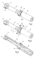
- FIG. 1 shows a diagrammatic illustration of a shank-type tool which is designed as a reamer and which has an integrated alignment mechanism
- FIG. 2 shows the shank-type tool as per FIG. 1 with unscrewed cylindrical adjusting screws with conical tips;
- FIG. 3 shows a longitudinal section through the shank-type tool as per FIG. 1 in a diagrammatic illustration
- FIG. 4 a shows a longitudinal section through the shank-type tool as per FIG. 1 with the adjusting screws screwed in;
- FIG. 4 b shows a longitudinal section corresponding to FIG. 4 a with the adjusting screws unscrewed
- FIG. 4 c shows a longitudinal section through the shank-type tool in a section plane without adjusting screws and with open encircling groove
- FIG. 4 d shows an illustration corresponding to FIG. 4 c with filler material in the groove
- FIG. 5 shows a section through a shank-type tool corresponding to FIG. 3 , with conical adjusting screws.
- the rotating shank-type tools illustrated in the drawing are reamers designed for use in machine tools.
- the shank-type tools have a shank 10 , a tool head 14 which is arranged on one shank end and which is equipped with a plurality of cutting elements 12 , and a coupling element 16 , which is arranged on the other shank end, for directly or indirectly attaching to a machine spindle (not illustrated).
- the shank 10 has, in its central region, a radially open circumferential groove 18 which extends over the circumference of the shank and which has a concavely curved groove base 35 , into which are inserted a plurality of radially adjustable spreading elements 20 which have a spacing to one another in the circumferential direction.
- the spreading elements 20 have a threaded section 22 which engages in each case into an internal thread 26 which is formed into the groove flanks 24 ′, 24 ′′ and which is interrupted by the circumferential groove 18 .
- the tool shank 10 is of substantially cylindrical design. Said tool shank 10 has a radially thickened portion 34 in the region of the encircling groove.
- the threaded section 22 of the spreading elements is of cylindrical design, while the internal threads 26 in the groove flanks complement one another so as to form a complementary internal cylinder.
- the spreading elements 20 have a conical tip 28 which bears against a complementary internal cone 30 , which is divided by the encircling groove, in the region of the groove flanks.
- a spreading force is in this case exerted by means of the respective cone tips 28 on the groove flanks 24 ′, 24 ′′ in the region of the internal cone 30 , which results in a radial adjustment of the tool head 14 relative to the coupling element 16 .
- the exemplary embodiment shown in FIG. 5 differs from the exemplary embodiment according to FIGS. 1 to 4 in that the spreading elements 20 have a conical threaded section 23 , while the internal thread 27 , which is divided by the circumferential groove 18 , in the groove flanks 24 ′, 24 ′′ is likewise of conical design.
- the conical threaded section 23 ensures that, when the spreading elements 20 are screwed in, spreading and bending forces are exerted on the groove flanks 24 ′, 24 ′′, which spreading and bending forces permit an alignment of the tool head 14 relative to the coupling element 16 .
- the circumferential groove 18 is filled with a filler material 32 at least in the region of the spreading elements.
- the filler material 32 may be inserted into the circumferential groove 18 in the form of a ring or in the form of ring segments, or may be introduced into the circumferential groove 18 in the form of a casting compound.
- the filler material 32 is expediently composed of a ductile, abrasion-resistant and adherent material, preferably of an elastomeric plastic.
- the filler material 32 firstly performs a sealing function with respect to contaminants from the outside.
- Said filler material 32 also serves to provide rotational locking of the spreading elements 20 such that these cannot become loosened from their internal threads on their own.
- the filler material has a vibration-damping effect on the rotating tool.
- spreading elements 20 have been provided which are arranged so as to be distributed over the circumference at intervals. It is basically possible for the number of spreading elements 20 to be adapted to the required run-out accuracy, wherein it must be taken into consideration that the adjusting expenditure is greater the more spreading elements 20 are provided distributed over the circumference.
- two-dimensional adjustment is attained by means of only two spreading elements with an angular spacing of 90° to one another if there is an elastic preload between the groove flanks in the opposite direction to the spreading action of the spreading elements.
- the preload may be generated either by means of mechanical and thermal material treatment in the groove region of the tool shank or by means of the formation of an eccentric circumferential groove.
- An improvement in this regard may be attained if filler material which influences the restoring action during the adjustment process is arranged in the circumferential groove.
- the invention relates to a shank-type tool for machine tools, having a shank 10 , a tool head which is arranged on one shank end and which is equipped with at least one cutting element 12 , and a coupling element 16 , which is arranged on the other shank end, for directly or indirectly attaching to a machine spindle.
- the shank 10 has a radially open circumferential groove 18 extending over the shank circumference and has at least one spreading element 20 which engages into the circumferential groove and which is radially adjustable therein so as to exert spreading and bending forces on the groove flanks 24 ′, 24 ′′.
- the circumferential groove 18 is filled, at least in the region of the spreading elements 20 , with a filler material 32 which performs both a sealing function with respect to contaminants and also a damping function. Furthermore, the filler material 32 serves to provide rotational locking of the spreading elements 20 .
Applications Claiming Priority (4)
| Application Number | Priority Date | Filing Date | Title |
|---|---|---|---|
| DE102008045675.6 | 2008-09-04 | ||
| DE102008045675A DE102008045675A1 (de) | 2008-09-04 | 2008-09-04 | Rundlaufendes Schaftwerkzeug |
| DE102008045675 | 2008-09-04 | ||
| PCT/EP2009/060782 WO2010026055A1 (de) | 2008-09-04 | 2009-08-20 | Rundlaufendes schaftwerkzeug |
Publications (2)
| Publication Number | Publication Date |
|---|---|
| US20110182679A1 US20110182679A1 (en) | 2011-07-28 |
| US9079253B2 true US9079253B2 (en) | 2015-07-14 |
Family
ID=41228428
Family Applications (1)
| Application Number | Title | Priority Date | Filing Date |
|---|---|---|---|
| US12/737,978 Active 2032-08-29 US9079253B2 (en) | 2008-09-04 | 2009-08-20 | Rotating shaft tool |
Country Status (7)
| Country | Link |
|---|---|
| US (1) | US9079253B2 (de) |
| EP (1) | EP2318167B1 (de) |
| JP (1) | JP2012501860A (de) |
| CN (1) | CN102143817B (de) |
| DE (1) | DE102008045675A1 (de) |
| IL (1) | IL211463A0 (de) |
| WO (1) | WO2010026055A1 (de) |
Cited By (2)
| Publication number | Priority date | Publication date | Assignee | Title |
|---|---|---|---|---|
| US20140260781A1 (en) * | 2013-03-15 | 2014-09-18 | General Electric Company | Torsional mode shifting |
| US9366313B2 (en) | 2013-03-15 | 2016-06-14 | General Electric Company | Torsional resonance frequency adjustor |
Families Citing this family (10)
| Publication number | Priority date | Publication date | Assignee | Title |
|---|---|---|---|---|
| US8529173B2 (en) | 2008-01-22 | 2013-09-10 | Valenite, Llc | Method to align characteristic frequency of material removal tool and rotation speed of spindle of machine tool and material removal tool so aligned |
| SE533786C2 (sv) * | 2009-05-25 | 2011-01-11 | Sandvik Intellectual Property | Anordning och förfarande för fräsning av material |
| SE535054C2 (sv) * | 2010-03-17 | 2012-03-27 | Sandvik Intellectual Property | Fräsverktyg för skärande bearbetning med dämpningsorgan anordnande i verktygskroppen |
| EP3050654B1 (de) * | 2015-01-30 | 2022-03-23 | Sandvik Intellectual Property AB | Werkzeug mit dummy-chip |
| KR101909923B1 (ko) * | 2015-02-10 | 2018-10-19 | 두산공작기계 주식회사 | 공작기계 |
| EP3222376B1 (de) * | 2016-03-24 | 2019-01-23 | Seco Tools AB | Nutenklinge, nutenwerkzeug und verfahren zum rillen eines metallischen werkstücks |
| DE102018108167A1 (de) * | 2018-04-06 | 2019-10-10 | Alfing Kessler Sondermaschinen Gmbh | Werkzeughalter |
| EP3868504A4 (de) * | 2018-10-18 | 2022-07-27 | Sumitomo Electric Tool Net, Inc. | Räumwerkzeug mit ölbohrung |
| WO2020108770A1 (en) * | 2018-11-30 | 2020-06-04 | Kyocera Unimerco Tooling A/S | Tool supporter with adjustment system and method for aligning a tool using the same |
| DE102019133734A1 (de) * | 2019-12-10 | 2021-06-10 | Blickle Werkzeuge GmbH & Co. KG | Reibahlen-Vorrichtung mit neuartigem Ahlenkopf |
Citations (21)
| Publication number | Priority date | Publication date | Assignee | Title |
|---|---|---|---|---|
| US3261236A (en) | 1965-03-08 | 1966-07-19 | Frank A Flannery | Cutting tool and method of cutting |
| SU986622A1 (ru) * | 1980-12-24 | 1983-01-07 | Дальневосточный Ордена Трудового Красного Знамени Политехнический Институт Им.В.В.Куйбышева | Расточна оправка |
| GB2164276A (en) | 1984-09-14 | 1986-03-19 | Beck August Gmbh Co | Axial clamping connection |
| EP0187647A2 (de) | 1985-01-10 | 1986-07-16 | J. Kühn GmbH & Co. Präzisionswerkzeug KG | Bohrwerkzeug |
| DE3715659A1 (de) | 1987-03-11 | 1988-09-22 | Guehring Gottlieb Fa | Kupplungssystem fuer spanabhebende schaftwerkzeuge |
| US5116171A (en) | 1989-09-05 | 1992-05-26 | Samson Ag | Pressure controlled cutter bit retainer with precision adjustable cutter bit |
| US5286042A (en) * | 1993-03-24 | 1994-02-15 | Hydra-Lock Corporation | Tool holder with centering adjustment |
| EP0656240A1 (de) | 1993-12-04 | 1995-06-07 | fischerwerke Artur Fischer GmbH & Co. KG | Bohrvorrichtung mit radial auslenkbarer Bohrspindel |
| DE4400425A1 (de) | 1994-01-08 | 1995-07-13 | Komet Stahlhalter Werkzeug | Vorrichtung zur Kupplung zweier Werkzeugteile |
| JPH10138011A (ja) * | 1996-11-08 | 1998-05-26 | Hiroyoshi Sakae | 切削工作機械のバイトおよび刃部用具、ならびにそれらを使用した刃先位置の調整方法 |
| EP1080832A2 (de) | 1999-08-30 | 2001-03-07 | Nt Tool Kabushikikaisha | Werkeughalter und Vorrichtung zum Ausrichten von Rundlauffehlern eines Werkzeughalters |
| GB2356828A (en) | 1999-12-03 | 2001-06-06 | Cogsdill Tool Prod | Cutting tool, such as a reamer. |
| US6345942B1 (en) * | 1997-07-09 | 2002-02-12 | Harold D. Cook | Method and apparatus for mitigating vibration associated with rotary cutting machine |
| US20020067961A1 (en) * | 2000-12-06 | 2002-06-06 | Cogsdill Tool Products, Inc. | Cutting tool |
| JP2003145378A (ja) * | 2001-11-15 | 2003-05-20 | Alps Tool Co Ltd | 工具ホルダ及び芯振れ修正具 |
| US20030138303A1 (en) | 2000-02-04 | 2003-07-24 | Konstantin Baxivanelis | Device for connecting two tool parts |
| DE202006000914U1 (de) | 2006-01-19 | 2006-03-16 | Giro, Armin | Spannzange |
| EP1757391A1 (de) | 2005-08-23 | 2007-02-28 | Schunk GmbH & Co. KG Spann- und Greiftechnik | Dehnspanneinrichtung |
| US7393164B2 (en) * | 2006-10-02 | 2008-07-01 | Primetool Mfg, Inc. | Dynamic balancing ring for cutter holder |
| US7455487B2 (en) * | 2006-01-17 | 2008-11-25 | Hsin-Tien Chang | Gyration balancing calibration free high-speed boring tool |
| US7938408B2 (en) * | 2004-06-14 | 2011-05-10 | Franz Haimer Maschinenbau Kg | Tool holder for a rotary tool |
Family Cites Families (5)
| Publication number | Priority date | Publication date | Assignee | Title |
|---|---|---|---|---|
| JPH0624710B2 (ja) * | 1985-09-18 | 1994-04-06 | オリンパス光学工業株式会社 | 微小物体操作装置 |
| JPH11349917A (ja) * | 1998-06-05 | 1999-12-21 | Nissei Technica:Kk | 緩み止め用のエアゾル型スプレー接着剤組成物 |
| JP2000055028A (ja) * | 1998-08-10 | 2000-02-22 | Japan Steel & Tube Constr Co Ltd | ボルト、ナットによる締結構造 |
| JP4598927B2 (ja) * | 1999-08-30 | 2010-12-15 | エヌティーツール株式会社 | 工具保持具 |
| CN100519016C (zh) * | 2007-05-30 | 2009-07-29 | 东风本田发动机有限公司 | 镗刀支承夹具及镗刀安装调整方法 |
-
2008
- 2008-09-04 DE DE102008045675A patent/DE102008045675A1/de not_active Withdrawn
-
2009
- 2009-08-20 JP JP2011525501A patent/JP2012501860A/ja active Pending
- 2009-08-20 WO PCT/EP2009/060782 patent/WO2010026055A1/de active Application Filing
- 2009-08-20 CN CN200980134459.8A patent/CN102143817B/zh active Active
- 2009-08-20 US US12/737,978 patent/US9079253B2/en active Active
- 2009-08-20 EP EP09782040.1A patent/EP2318167B1/de active Active
-
2011
- 2011-02-28 IL IL211463A patent/IL211463A0/en active IP Right Grant
Patent Citations (25)
| Publication number | Priority date | Publication date | Assignee | Title |
|---|---|---|---|---|
| US3261236A (en) | 1965-03-08 | 1966-07-19 | Frank A Flannery | Cutting tool and method of cutting |
| SU986622A1 (ru) * | 1980-12-24 | 1983-01-07 | Дальневосточный Ордена Трудового Красного Знамени Политехнический Институт Им.В.В.Куйбышева | Расточна оправка |
| GB2164276A (en) | 1984-09-14 | 1986-03-19 | Beck August Gmbh Co | Axial clamping connection |
| DE3433878A1 (de) | 1984-09-14 | 1986-03-27 | August Beck GmbH & Co, 7472 Winterlingen | Axial-spannverbindung |
| EP0187647A2 (de) | 1985-01-10 | 1986-07-16 | J. Kühn GmbH & Co. Präzisionswerkzeug KG | Bohrwerkzeug |
| DE3715659A1 (de) | 1987-03-11 | 1988-09-22 | Guehring Gottlieb Fa | Kupplungssystem fuer spanabhebende schaftwerkzeuge |
| US4813831A (en) | 1987-03-11 | 1989-03-21 | Gottlieb Guhring Kg | Coupling system for cutting shank tools |
| US5116171A (en) | 1989-09-05 | 1992-05-26 | Samson Ag | Pressure controlled cutter bit retainer with precision adjustable cutter bit |
| US5286042A (en) * | 1993-03-24 | 1994-02-15 | Hydra-Lock Corporation | Tool holder with centering adjustment |
| EP0656240A1 (de) | 1993-12-04 | 1995-06-07 | fischerwerke Artur Fischer GmbH & Co. KG | Bohrvorrichtung mit radial auslenkbarer Bohrspindel |
| US5540527A (en) | 1993-12-04 | 1996-07-30 | Fischerwerke Artur Fischer Gmbh & Co. Kg | Drilling device having a radially displacable drill shank |
| DE4400425A1 (de) | 1994-01-08 | 1995-07-13 | Komet Stahlhalter Werkzeug | Vorrichtung zur Kupplung zweier Werkzeugteile |
| JPH10138011A (ja) * | 1996-11-08 | 1998-05-26 | Hiroyoshi Sakae | 切削工作機械のバイトおよび刃部用具、ならびにそれらを使用した刃先位置の調整方法 |
| US6345942B1 (en) * | 1997-07-09 | 2002-02-12 | Harold D. Cook | Method and apparatus for mitigating vibration associated with rotary cutting machine |
| EP1080832A2 (de) | 1999-08-30 | 2001-03-07 | Nt Tool Kabushikikaisha | Werkeughalter und Vorrichtung zum Ausrichten von Rundlauffehlern eines Werkzeughalters |
| US6557445B1 (en) * | 1999-08-30 | 2003-05-06 | Nt Tool Kabushiki Kaisha | Tool holder and a runout correcting tool for a tool holder |
| GB2356828A (en) | 1999-12-03 | 2001-06-06 | Cogsdill Tool Prod | Cutting tool, such as a reamer. |
| US20030138303A1 (en) | 2000-02-04 | 2003-07-24 | Konstantin Baxivanelis | Device for connecting two tool parts |
| US20020067961A1 (en) * | 2000-12-06 | 2002-06-06 | Cogsdill Tool Products, Inc. | Cutting tool |
| JP2003145378A (ja) * | 2001-11-15 | 2003-05-20 | Alps Tool Co Ltd | 工具ホルダ及び芯振れ修正具 |
| US7938408B2 (en) * | 2004-06-14 | 2011-05-10 | Franz Haimer Maschinenbau Kg | Tool holder for a rotary tool |
| EP1757391A1 (de) | 2005-08-23 | 2007-02-28 | Schunk GmbH & Co. KG Spann- und Greiftechnik | Dehnspanneinrichtung |
| US7455487B2 (en) * | 2006-01-17 | 2008-11-25 | Hsin-Tien Chang | Gyration balancing calibration free high-speed boring tool |
| DE202006000914U1 (de) | 2006-01-19 | 2006-03-16 | Giro, Armin | Spannzange |
| US7393164B2 (en) * | 2006-10-02 | 2008-07-01 | Primetool Mfg, Inc. | Dynamic balancing ring for cutter holder |
Non-Patent Citations (4)
| Title |
|---|
| Form PCT/IPEA/409 International Preliminary Examination Report dated Feb. 22, 2011 (10 pages). |
| Form PCT/IPEA/416 Notification of Transmittal of International Preliminary Examination Report dated Feb. 22, 2011 (1 page). |
| Form PCT/ISA/210 International Search Report dated Nov. 17, 2009 (4 pages) with English translation of Categories of Documents Cited. |
| Germany Patent Office Search Report dated Feb. 27, 2009 (4 pages) with English translation of p. 2. |
Cited By (3)
| Publication number | Priority date | Publication date | Assignee | Title |
|---|---|---|---|---|
| US20140260781A1 (en) * | 2013-03-15 | 2014-09-18 | General Electric Company | Torsional mode shifting |
| US9366313B2 (en) | 2013-03-15 | 2016-06-14 | General Electric Company | Torsional resonance frequency adjustor |
| US9551398B2 (en) * | 2013-03-15 | 2017-01-24 | General Electric Company | Torsional mode shifting |
Also Published As
| Publication number | Publication date |
|---|---|
| EP2318167A1 (de) | 2011-05-11 |
| US20110182679A1 (en) | 2011-07-28 |
| WO2010026055A1 (de) | 2010-03-11 |
| IL211463A0 (en) | 2011-05-31 |
| DE102008045675A1 (de) | 2010-03-11 |
| EP2318167B1 (de) | 2015-07-15 |
| CN102143817B (zh) | 2014-03-12 |
| CN102143817A (zh) | 2011-08-03 |
| JP2012501860A (ja) | 2012-01-26 |
Similar Documents
| Publication | Publication Date | Title |
|---|---|---|
| US9079253B2 (en) | Rotating shaft tool | |
| US10259049B2 (en) | Tool holder having a collet holder and a tool insert for use in a tool holder | |
| RU2265501C2 (ru) | Расточная шпоночная фреза | |
| JP5808810B2 (ja) | 独立した調心部およびトルク伝達部を有するt溝フライス | |
| CN103506866B (zh) | 具有整合的阻尼装置的刀具适配器 | |
| US9901988B2 (en) | Tool receptacle for a screw-in tool | |
| JP2010532274A (ja) | マルチピース工具組立体及び切削工具 | |
| KR102227667B1 (ko) | 스틱 블레이드를 이용한 외주 절삭 공구 | |
| SE534679C2 (sv) | Verktyg för skärande bearbetning med elastisk flexibel montering av två verktygsdelar | |
| US7322777B2 (en) | Reamer with clamping arrangement for adjusting cutting insert and other cutting tools with clamping arrangements for adjusting cutting inserts | |
| CN107921552B (zh) | 可更换切削刀头、刀具保持器和旋转切削刀具 | |
| US8899597B2 (en) | Clamping system | |
| KR101637048B1 (ko) | 체결 유닛을 포함하는 공구 | |
| US7396196B2 (en) | Cutting machining tool | |
| US9901994B2 (en) | Rotating tool and tool head | |
| RU2572945C2 (ru) | Режущий инструмент с установленным на хвостовике регулировочным кольцом | |
| US9713850B2 (en) | Reaming tool and adjusting screw for a fine adjustment mechanism, in particular for a reaming tool | |
| JP5646615B2 (ja) | 双方向調節機構を有する切削工具 | |
| JP6533289B2 (ja) | 工作機械用工具 | |
| CN105813787A (zh) | 刀片安装机构、旋转切削工具、工具躯体、楔子部件及调整部件 | |
| US10376974B2 (en) | Sectional hob | |
| WO2020108770A1 (en) | Tool supporter with adjustment system and method for aligning a tool using the same | |
| US10189090B2 (en) | Drilling tool | |
| JP5167686B2 (ja) | 切削工具 | |
| DE19629610A1 (de) | Einfaches Feinverstellsystem für einschneidige Bohrstangen |
Legal Events
| Date | Code | Title | Description |
|---|---|---|---|
| AS | Assignment |
Owner name: KOMET GROUP GMBH, GERMANY Free format text: ASSIGNMENT OF ASSIGNORS INTEREST;ASSIGNORS:BIERL, WOLFGANG;HILTY, BASTIAN;SIGNING DATES FROM 20110224 TO 20110318;REEL/FRAME:026212/0888 |
|
| STCF | Information on status: patent grant |
Free format text: PATENTED CASE |
|
| MAFP | Maintenance fee payment |
Free format text: PAYMENT OF MAINTENANCE FEE, 4TH YEAR, LARGE ENTITY (ORIGINAL EVENT CODE: M1551); ENTITY STATUS OF PATENT OWNER: LARGE ENTITY Year of fee payment: 4 |
|
| MAFP | Maintenance fee payment |
Free format text: PAYMENT OF MAINTENANCE FEE, 8TH YEAR, LARGE ENTITY (ORIGINAL EVENT CODE: M1552); ENTITY STATUS OF PATENT OWNER: LARGE ENTITY Year of fee payment: 8 |