US9050078B2 - Implanted medical device useful for cosmetic surgery - Google Patents
Implanted medical device useful for cosmetic surgery Download PDFInfo
- Publication number
- US9050078B2 US9050078B2 US13/379,360 US201013379360A US9050078B2 US 9050078 B2 US9050078 B2 US 9050078B2 US 201013379360 A US201013379360 A US 201013379360A US 9050078 B2 US9050078 B2 US 9050078B2
- Authority
- US
- United States
- Prior art keywords
- distal
- anchor
- proximal
- connecting element
- elongated connecting
- Prior art date
- Legal status (The legal status is an assumption and is not a legal conclusion. Google has not performed a legal analysis and makes no representation as to the accuracy of the status listed.)
- Expired - Fee Related, expires
Links
Images


Classifications
-
- A—HUMAN NECESSITIES
- A61—MEDICAL OR VETERINARY SCIENCE; HYGIENE
- A61B—DIAGNOSIS; SURGERY; IDENTIFICATION
- A61B17/00—Surgical instruments, devices or methods, e.g. tourniquets
- A61B17/04—Surgical instruments, devices or methods, e.g. tourniquets for suturing wounds; Holders or packages for needles or suture materials
- A61B17/0401—Suture anchors, buttons or pledgets, i.e. means for attaching sutures to bone, cartilage or soft tissue; Instruments for applying or removing suture anchors
- A61B2017/0409—Instruments for applying suture anchors
-
- A—HUMAN NECESSITIES
- A61—MEDICAL OR VETERINARY SCIENCE; HYGIENE
- A61B—DIAGNOSIS; SURGERY; IDENTIFICATION
- A61B17/00—Surgical instruments, devices or methods, e.g. tourniquets
- A61B17/04—Surgical instruments, devices or methods, e.g. tourniquets for suturing wounds; Holders or packages for needles or suture materials
- A61B17/0401—Suture anchors, buttons or pledgets, i.e. means for attaching sutures to bone, cartilage or soft tissue; Instruments for applying or removing suture anchors
- A61B2017/0412—Suture anchors, buttons or pledgets, i.e. means for attaching sutures to bone, cartilage or soft tissue; Instruments for applying or removing suture anchors having anchoring barbs or pins extending outwardly from suture anchor body
-
- A—HUMAN NECESSITIES
- A61—MEDICAL OR VETERINARY SCIENCE; HYGIENE
- A61B—DIAGNOSIS; SURGERY; IDENTIFICATION
- A61B17/00—Surgical instruments, devices or methods, e.g. tourniquets
- A61B17/04—Surgical instruments, devices or methods, e.g. tourniquets for suturing wounds; Holders or packages for needles or suture materials
- A61B17/0401—Suture anchors, buttons or pledgets, i.e. means for attaching sutures to bone, cartilage or soft tissue; Instruments for applying or removing suture anchors
- A61B2017/0414—Suture anchors, buttons or pledgets, i.e. means for attaching sutures to bone, cartilage or soft tissue; Instruments for applying or removing suture anchors having a suture-receiving opening, e.g. lateral opening
-
- A—HUMAN NECESSITIES
- A61—MEDICAL OR VETERINARY SCIENCE; HYGIENE
- A61B—DIAGNOSIS; SURGERY; IDENTIFICATION
- A61B17/00—Surgical instruments, devices or methods, e.g. tourniquets
- A61B17/04—Surgical instruments, devices or methods, e.g. tourniquets for suturing wounds; Holders or packages for needles or suture materials
- A61B17/0401—Suture anchors, buttons or pledgets, i.e. means for attaching sutures to bone, cartilage or soft tissue; Instruments for applying or removing suture anchors
- A61B2017/0417—T-fasteners
-
- A—HUMAN NECESSITIES
- A61—MEDICAL OR VETERINARY SCIENCE; HYGIENE
- A61B—DIAGNOSIS; SURGERY; IDENTIFICATION
- A61B17/00—Surgical instruments, devices or methods, e.g. tourniquets
- A61B17/04—Surgical instruments, devices or methods, e.g. tourniquets for suturing wounds; Holders or packages for needles or suture materials
- A61B17/0401—Suture anchors, buttons or pledgets, i.e. means for attaching sutures to bone, cartilage or soft tissue; Instruments for applying or removing suture anchors
- A61B2017/042—Suture anchors, buttons or pledgets, i.e. means for attaching sutures to bone, cartilage or soft tissue; Instruments for applying or removing suture anchors plastically deformed during insertion
-
- A—HUMAN NECESSITIES
- A61—MEDICAL OR VETERINARY SCIENCE; HYGIENE
- A61B—DIAGNOSIS; SURGERY; IDENTIFICATION
- A61B17/00—Surgical instruments, devices or methods, e.g. tourniquets
- A61B17/04—Surgical instruments, devices or methods, e.g. tourniquets for suturing wounds; Holders or packages for needles or suture materials
- A61B17/0401—Suture anchors, buttons or pledgets, i.e. means for attaching sutures to bone, cartilage or soft tissue; Instruments for applying or removing suture anchors
- A61B2017/0464—Suture anchors, buttons or pledgets, i.e. means for attaching sutures to bone, cartilage or soft tissue; Instruments for applying or removing suture anchors for soft tissue
Definitions
- the present invention relates to innovations for minimally invasive plastic and/or cosmetic surgery. More specifically the present invention relates to methods for manipulating tissue placement using anchors and sutures. Conducting tools are also described, for delivering these elements through the tissue and fixing them as desired.
- the system and method arc useful for smoothing wrinkles, reconstructive purposes, and the like.
- US patent application US20070293892 discloses a surgical thread for plastic surgery which effectively removes sagging and wrinkling of skin.
- the device comprises a thread shaped member comprised of a thread body, to be implanted in the inside layers of the skin, partially formed in its longitudinal direction with projections for anchoring in the inside skin layers, wherein at least the thread body is comprised of an absorbable thread, and the thread body or the projections are formed with residual film parts which will not be absorbed by the inside skin layers, and a method of imparting tension to the skin using the same.
- this device is depicted.
- the system is somewhat primitive in its capabilities. For example, it cannot provide independent control over tension between successive anchoring projections. Nor does it allow for both tension and compression to be provided by the same device. Finally the device does not allow for certain operations such as gathering tissue together.
- US patent application 2007/067045 discloses an implant that reduces wrinkles, in the shape of a cylinder with a constant or varying cross-section and length.
- the implant contains a gel of limited flow capability.
- the implant can also be a balloon that may or may not have multiple compartments optionally filled with fluid.
- the system cannot provide independent control over tension between given points. Nor does it allow for both tension and compression to be provided by the same device. Finally the device does not allow for certain operations such as gathering tissue together.
- PCT application WO06065837 provides a cosmetic implant comprising a filament made from a biocompatible elastomer.
- the elastomeric filament can be injected or pulled under one or more wrinkles. Once implanted under the wrinkle(s), the filament lifts and supports the tissue above it. Such lifting lessens (and possibly removes altogether) the appearance of the wrinkle(s).
- the system cannot provide independent control over tension between given anchoring points. Nor does it allow for both tension and compression to be provided by the same device. Finally the system does not allow for certain operations such as gathering tissue together at a point.
- the cosmetic implants are sutures are made from polypropylene and contain cones located along the suture. The suture is inserted via an incision, deployed, anchored via the cones and then the suture is fixated to the fascia thereby a tension is produced which lifts the sagging tissue.
- the device comprises:
- the distal and proximal anchors are characterized by at least two configurations: (i) a FOLDED CONFIGURATION, in which the distal and proximal anchors are substantially parallel to the main longitudinal axis; and, (ii) a DEPLOYED CONFIGURATION, in which the distal anchor is positioned at an angle A with respect to the main longitudinal axis, and the proximal anchor is positioned at an angle B with respect to the main longitudinal axis.
- the fixation device further comprises deployment means adapted to deploy the distal and proximal anchors by reconfiguring the same from the FOLDED CONFIGURATION to the DEPLOYED CONFIGURATION.
- fixation device as defined above, wherein the fixation device further comprises tension varying means connectable to the distal and proximal anchors, adapted to alter parameters selected from a group consisting of: the length of the elongated connecting element; and, the tension applied on the elongated connecting element, such that the first and the second tissue locations are repositioned with respect to each other according to the parameters.
- each of the distal and the proximal anchors comprises at least two hinged wings; each of the hinged wing being characterized by at least two configurations: (i) a FOLDED CONFIGURATION, in which the wings are substantially parallel to the main longitudinal axis, such that the anchor is folded and, (ii) a DEPLOYED CONFIGURATION, in which the wings are positioned at angles selected from a group consisting of the angles A or B, such that the anchor is deployed.
- the deployment mechanism comprises at least one deployment tool, reversible coupled to at least one of the wings, such that application of a mechanical force by the at least one deployment tool to the wings is adapted to reconfigure at least one of the wings from the FOLDED CONFIGURATION into the DEPLOYED CONFIGURATION so as to deploy the anchors.
- the at least one deployment tool is selected from a group consisting of: a rod, a stick, a shaft, a needle, a pin, a wire, a thread, a suture, a string, a cord, a fiber, a rope, or any combination thereof.
- fixation device as defined above, wherein the fixation device further comprises a conducting tool adapted to keep the distal and proximal anchors in the FOLDED CONFIGURATION, and to facilitate the conduction of the distal and proximal anchors to the first and second tissue locations.
- the distal and proximal anchors are comprised of materials selected from the group consisting of: polyethylene, polypropylene, polyurethanes, poly (methyl methacrylate), polycarbonates, silicone rubber, biodegradable polymers, synthetic and natural occurring materials including polyalkylene esters, polylactic acid and its co-polymers, polyvinyl esters, polyvinyl alcohol, polyanhydrides, and polycarbonates, Polydioxanone (PDO), Polycaprolactone (PCL), Polylactic acid (PLA), Polyglycolic acid (PGA), Adipic acid, PEG, glutamic acid, polymers, metals, metal alloys, ceramics, shape memory alloys, hydroxyapaptite, and glass.
- fixation device as defined above, wherein the fixation device is adapted to create a network of anchors.
- the method comprises steps of:
- step (a) is performed by providing a fixation device with distal and proximal anchors which are characterized by at least two configurations: (i) a FOLDED CONFIGURATION, in which the distal and proximal anchors arc substantially parallel to the main longitudinal axis; and, (ii) a DEPLOYED CONFIGURATION, in which the distal anchor is positioned at an angle A with respect to the main longitudinal axis, and the proximal anchor is positioned at an angle B with respect to the main longitudinal axis.
- Steps (c)-(d) comprise additional steps of reconfiguring the distal and proximal anchors from the FOLDED CONFIGURATION to the DEPLOYED CONFIGURATION via a deployment means.
- fixation method as defined above, which further comprises steps of: (e) providing the fixation device with tension varying means connectable to the distal and proximal anchors; (f) altering the parameters selected from a group consisting of: the length of the elongated connecting element; and, the tension applied on the elongated connecting element; (g) repositioning the first and the second tissue locations with respect to each other according to the parameters; (h) securing the proximal anchor to the elongated connecting element.
- fixation method as defined above, which further comprises steps of: (e) providing the fixation device with distal and the proximal anchors comprises at least two hinged wings; each of the hinged wing being characterized by at least two configurations: (i) a FOLDED CONFIGURATION, in which the wings are substantially parallel to the main longitudinal axis, such that the anchor is folded and, (ii) a DEPLOYED CONFIGURATION, in which the wings are positioned at angles selected from a group consisting of the angles A or B, such that the anchor is deployed.
- fixation method as defined above, which further comprises steps of: providing the fixation device with a deployment mechanism which comprises at least one deployment tool reversible coupled to at least one of the wings; and, applying a mechanical force by the at least one deployment tool to the wings, and thereby reconfiguring the at least one of the wings from the FOLDED CONFIGURATION into the DEPLOYED CONFIGURATION.
- fixation method as defined above, which further comprises steps of: providing the fixation device with a conducting tool for keeping the distal and proximal anchors in the FOLDED CONFIGURATION; and, facilitating the insertion of the distal and proximal anchors to the first and second tissue locations via the conducting tool while performing the steps (c)-(d).
- PDO Polydioxanone
- PCL Polycaprolactone
- PDA Polylactic acid
- PGA Polyglycolic acid
- Adipic acid PEG, glutamic acid
- fixation method as defined above, which further comprises step of coating the distal and proximal anchors, the elongated connecting element, and the conducting tool with a material selected from the group consisting of: proteins, growth factors, antigens, carbon-like diamond, carbon, hyaluronic acid, collagen, silver, gold, or any combination thereof.
- fixation method as defined above, which further comprises steps of: removing at least part of the deployment mechanism from the fixation device; and, leaving the distal and proximal anchors in the DEPLOYED CONFIGURATION with a predetermined tension in the elongated connecting element therebetween.
- FIGS. 1A-1B shows prior art concerning contour ThreadsTM
- FIG. 2 schematically illustrates specific embodiment of the distal anchor according to the present invention
- FIGS. 3 a - b schematically illustrates the anchors of the present invention with two hinges wings
- FIGS. 4 a - c schematically illustrate a possible method for the reconfiguration of a distal anchor from the FOLDED CONFIGURATION into the DEPLOYED CONFIGURATION;
- FIGS. 5 a - c schematically illustrate a possible method for the reconfiguration of a proximal anchor from the FOLDED CONFIGURATION into the DEPLOYED CONFIGURATION;
- FIG. 6 schematically illustrates distal anchor 10 and proximal anchor 20 in their DEPLOYED CONFIGURATION
- FIG. 7 schematically illustrates a specific embodiment of all the elements of the fixation device with a conducting tool
- FIGS. 8 a - g schematically illustrate the steps for the operation of the fixation device in the process of anchoring distal and proximal anchors
- FIGS. 9 a - 9 j schematically illustrate a specific embodiment of the fixation device of the present invention.
- FIGS. 10 a - 10 o schematically illustrate another embodiment of the present invention, and another method for performing the implantation according to the present invention
- FIGS. 11 a - c schematically illustrate the way an anchor is anchored at a predetermined tissue location
- FIG. 12 is a finite element analysis of an anchor
- FIGS. 13 a - b illustrate another embodiment of an anchor according to the present invention
- FIGS. 14 a - b illustrate distal and proximal anchors which are rotatable
- FIGS. 15 a - g illustrate method steps for the operation of a fixation device with rotatable anchors
- FIG. 16 illustrates a photo of an example prototype of the device
- FIG. 17 illustrates the device of the present invention in the experiments of Example 1.
- FIGS. 18 a - d illustrates graphs according to the result of the experiments of Example 1.
- FIGS. 19 a - o illustrate photographs of pigs according to the experiments of Example 1.
- FIGS. 20 a - d illustrate histological images according to the experiments of Example 1.
- FIGS. 21 a - c illustrate trials which were undertaken by using the device of the present invention in a chicken breast.
- FIG. 22 illustrates Stress Vs. time results graph.
- FIG. 23 illustrates Stress Vs. Strain results graph.
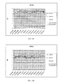
- FIG. 24 shows the implant measurements raw data.
- FIG. 25 shows the implant measurements raw data.
- the present invention discloses a minimally invasive multipoint fixation device adapted to laparoscopically locally reposition body tissues.
- the device comprises:
- the distal and proximal anchors are characterized by at least two configurations: (i) a FOLDED CONFIGURATION, in which the distal and proximal anchors are substantially parallel to the main longitudinal axis; and, (ii) a DEPLOYED CONFIGURATION, in which the distal anchor is positioned at an angle A with respect to the main longitudinal axis, and the proximal anchor is positioned at an angle B with respect to the main longitudinal axis.
- the fixation device further comprises deployment means adapted to deploy the distal and proximal anchors by reconfiguring the same from the FOLDED CONFIGURATION to the DEPLOYED CONFIGURATION.
- conducting tool refers hereinafter to a generally long thin hollow cylindrical or oval device adapted to be inserted within a small incision, in a fashion similar to a catheter/canula or laparoscopic/endoscopic tool.
- anchor refers hereinafter to a barbed structure adapted to be embedded irreversibly within bodily tissues, being rigidly held in place due to its barbs which are penetrating the surrounding tissue.
- biocompatible materials refers hereinafter to materials that have the ability to perform with an appropriate host response in a specific application. Biocompatible materials have the quality of not having toxic or injurious effects on biological systems.
- biodegradable materials refers hereinafter to materials that are degraded by the body's enzymatic pathways through a reaction against “foreign” material; or simply by hydrolysis.
- biodegradable materials are polymers such as Polydioxanone (PDO), Polycaprolactone (PCL), Polylactic acid (PLA), Polyglycolic acid (PGA), Adipic acid, PEG and glutamic acid.
- implantable refers to the property of an object which can be introduced into the human body at a distance from the location wherein the implanting device enters the body.
- repositioning refers hereinafter to any surgical operations possible including cosmetic surgeries selected from remolding and/or reconstructing both soft and/or hard tissues; repairing tears, holes, or apertures in soft biological tissue; organ repositioning and/or reconstruction; wrinkle removal; face lifting; intensive and/or immediate care for repairing ruptures of blood vessels, skin, or other tissue; repair of lacerations; orthopedic surgeries; dental surgeries; soft and hard tissue reattachment; and others that will be obvious to one skilled in the art.
- remolding refers to a process of reshaping, in particular reshaping skin, organ, and/or muscle.
- cosmetic surgery for instance often involves a process of remolding the face tissue and/or muscle.
- single point fixation refers to a fixation made by anchors for repositioning of tissues in a single point (an example of a single point fixation can be seen in FIGS. 1A and 1B ). It should be pointed out that there might be multiple anchors along the suture; however, if the fixation is made along the path/curve of the suture, it will be regarded as single point fixation.
- multi-point fixation refers to a fixation made by anchors for repositioning of tissues in multiple number of points.
- the fixation to the tissue is provided at an angle A relatively to the suture.
- Angle A can be in the range of above 0 and below 180 degrees, preferably 90 degrees.
- FIG. 2 An example of multi point fixation device can be seen in FIG. 2 , in which the fixation to the tissue is provided at an angle A relatively to the suture.
- the term “locally” refers herein after to a procedure that is carried out locally without having a need to be attached to the fascia layer and/or to the bone.
- minimally invasive procedure refers hereinafter to any procedure (surgical or otherwise) that is less invasive than open surgery used for the same purpose.
- the physician enters body of a patient through an incision made to the skin or through a body cavity or anatomical opening, but with the smallest damage possible.
- the incision made is big enough to enable a working port to perform the procedure but small enough to provide a short healing time and a short downtime.
- pressing is a mechanical operation in which a mechanical force is actuated in a direction which is distal to the operator.
- the term ‘pulling’ is a mechanical operation in which a mechanical force is actuated in a direction which is proximal to the operator.
- a device and method for tissues and skin manipulation is provided.
- the device is provided with ability to smooth skin by stretching or compressing the same. This procedure may also be used reduce wrinkles and achieve other aesthetic results.
- the device may also be used to lift tissue and reposition it.
- any esthetic procedure in which a skin is reposition from on point to another point is performed, can be achieved via the device of the present invention.
- One of the main advantages of the device provided by the present invention is the fact that the achieved esthetic outcome is provided via a minimally invasive method (e.g., a laparoscopic procedure).
- the present invention is intended in one embodiment for facial rejuvenation by lifting and repositioning sagging face tissues using a laparoscopic technique.
- the device is intended for breast lifting, posterior (buttocks) lifting, etc.
- the main target audiences of the present invention are women and men aged 35-70.
- the present invention may be utilized for facial nerve paralysis.
- Facial nerve paralysis is a common problem that involves the paralysis of any structures innervated by the facial nerve.
- the pathway of the facial nerve is long and relatively convoluted, so there are a number of causes that may result in facial nerve paralysis.
- the most common is Bell's palsy, an idiopathic disease that may only be diagnosed by exclusion.
- the device of the current invention may be beneficially employed for stretching a wrinkle or reposition tissues in the following manner: an anchor as described above is affixed to the facial muscle tissue and to the skin at one side of the wrinkle. According to another embodiment, the anchor can be affixed underneath the muscles above the bones.
- FIG. 2 schematically illustrates a specific embodiment of a distal anchor 10 ; and, a proximal anchor 20 interconnected therebetween.
- This figure illustrates the final result of the anchoring process of distal and proximal anchors 10 and 20 by using the fixation device of the present invention which is discloses below.
- Each of the anchors comprises attachment elements which may be example: barbs, cogs, spikes, etc.
- the attachment elements are adapted to connect distal anchor 10 to a first tissue location 12 , and to connect proximal anchor 20 to second tissue location 22 .
- the connection of the attachment elements may be performed by hooking into the surrounding tissue and becoming entrenched (as in FIGS. 11 a - c ).
- distal and proximal anchors 10 and 20 are anchored and entrenched at first and second tissue locations 12 and 22 , they serve as anchors. This means that they can be used for pulling and repositioning first and the second tissue location 12 and 22 with respect to each other by means of an elongated connecting element 30 (e.g., a thread, a suture, a string, a cord, a fiber, a rope, a wire, a rod, a stick, a shaft, etc.).
- an elongated connecting element 30 e.g., a thread, a suture, a string, a cord, a fiber, a rope, a wire, a rod, a stick, a shaft, etc.
- the elongated connecting element may be selected from a group consisting of: a rigid element or a non-rigid element.
- the distal and the proximal anchors may comprise attachment elements on both sides of the anchors.
- the anchors may comprise the attachment elements on only one side of the anchors.
- the distal and the proximal anchors 10 and 20 are useful for being anchored in tissue layers under muscle layers (e.g., between the dermis and the muscle).
- FIGS. 3 a - b schematically illustrate a specific embodiment of a minimally invasive multipoint fixation device 100 according to the present invention.
- Fixation device 100 of FIGS. 3 a - b is adapted to laparoscopically locally reposition body tissues.
- Fixation device 100 comprises the following main components:
- a main novel feature of the present invention is the ability of distal and proximal anchors 10 and 20 to be deployed.
- distal and proximal anchors 10 and 20 are characterized by two configurations: (i) a FOLDED CONFIGURATION (as illustrated in FIG. 3 a ), in which distal and proximal anchors 10 and 20 are substantially parallel to axis X; and, (ii) a DEPLOYED CONFIGURATION (shown in FIG. 4 c and in FIG. 5 c ), in which distal anchor 10 is positioned at an angle A with respect to axis X, and proximal anchor 20 is positioned at an angle B with respect to axis X.
- angles A and B may be in a range of about 0.1 degrees and about 180 degrees. Preferably, said angles A and B are about 90 degrees.
- fixation device 100 of the present invention is a deployment means 40 which is adapted to deploy distal and proximal anchors 10 and 20 by reconfiguring the same from the FOLDED CONFIGURATION to the DEPLOYED CONFIGURATION.
- elongated connecting element 30 is selected from a group consisting of: a thread, a suture, a string, a cord, a fiber, a rope, a wire, a rod, a stick, a shaft, or any combination thereof.
- elongated connecting element 30 is a suture.
- FIG. 3 b schematically illustrates distal anchor 10 which comprises two hinged wings 11 and 12 each of which is characterized by two configurations: (i) a FOLDED CONFIGURATION, in which said wings are substantially parallel to axis X, such that distal anchor 10 is folded; and, (ii) a DEPLOYED CONFIGURATION, in which hinged wings 11 and 12 are positioned at an angle A relatively to axis X, such that distal anchor 10 is deployed.
- proximal anchor 20 also comprises two hinged wings each of which is characterized by two configurations: (i) a FOLDED CONFIGURATION, in which said wings are substantially parallel to axis X, such that proximal anchor 20 is folded; and, (ii) a DEPLOYED CONFIGURATION, in which the hinged wings are positioned at an angle B (not shown) relatively to axis X, such that proximal anchor 20 is deployed.
- deployment mechanism 40 comprises a deployment tool 41 , reversible coupled to wings 10 and 11 via rigid rods 13 and 14 .
- Deployment tool 41 is adapted to reconfigure wings 11 and 12 from the FOLDED CONFIGURATION into the DEPLOYED CONFIGURATION by applying a mechanical pulling force F on the same, and thereby to deploy distal anchor 10 .
- the mechanical pulling force F which deploys distal anchor 10 is applied on deployment tool 41 via a pushing rod (not shown) which is an additional element of deployment mechanism 40 .
- This deployment is performed while the left end 9 of distal anchor 10 is held by the operator and/or via other means (e.g., an elongated connecting element).
- the deployment of distal anchor 10 may be performed by pulling left end 9 towards the proximal direction.
- the mechanical forces which may activate the deployment of distal and proximal anchors 10 and 20 may be for example: pushing forces, pulling forces, shearing forces, bending forces, torque, or any combination thereof.
- FIGS. 4 a - c illustrate a possible method for the reconfiguration of distal anchor 10 from the FOLDED CONFIGURATION into the DEPLOYED CONFIGURATION.
- distal anchor 10 is illustrated in the FOLDED CONFIGURATION.
- a pushing rod 42 which is adapted to actuate a pushing mechanical force F on deployment tool 41 to deploy distal anchor 10 .
- deployment tool 41 slides on rigid rod 15 when pushed by pushing rod 42 .
- FIG. 4 b illustrated distal anchor 10 in the process of its deployment between the FOLDED CONFIGURATION and the DEPLOYED CONFIGURATION.
- pushing rod 42 has begun to push deployment tool 41 , and as a result of that, wings 11 and 12 are deployed.
- FIG. 4 c illustrated distal anchor 10 in the DEPLOYED CONFIGURATION.
- deployment tool 41 is coupled to wings 11 and 12 , so as to increase the mechanical strength of the distal anchor in the DEPLOYED CONFIGURATION.
- the increase of the mechanical strength is performed by fixation of rigid rods 13 and 14 in grooves 17 and 18 located within wings 11 and 12 .
- FIGS. 5 a - c illustrate a possible method for the reconfiguration of proximal anchor 20 from the FOLDED CONFIGURATION into the DEPLOYED CONFIGURATION.
- proximal anchor 20 is illustrated in the FOLDED CONFIGURATION.
- a pulling suture 43 which is adapted to actuate a pushing force F on deployment tool 51 (which is part of deployment mechanism 40 ) to deploy proximal anchor 20 .
- deployment tool 51 which is part of deployment mechanism 40
- rigid rods 18 and 19 deliver said force F to wings 21 and 22 of proximal anchor 20 , and a result of that, proximal anchor is deployed.
- deployment tool 40 slides on rigid rod 15 when pulled by pulling suture 43 .
- FIG. 5 b illustrated proximal anchor 20 in the process of its deployment, between the FOLDED CONFIGURATION and the DEPLOYED CONFIGURATION. In this process, pulling suture 43 has begun to pull deployment tool 51 , and as a result of that, wings 18 and 19 are deployed.
- FIG. 5 c illustrated proximal anchor 20 in the DEPLOYED CONFIGURATION.
- deployment tool 51 is coupled to wings 18 and 19 , so as to increase the mechanical strength of proximal anchor 20 in the DEPLOYED CONFIGURATION.
- the increase of the mechanical strength is performed by fixation of rigid rods (not shown) in grooves (not shown) located within wings 18 and 19 .
- the deployment tool may be for example: a rod, a stick, a shaft, a needle, a pin, a wire, a thread, a suture, a string, a cord, a fiber, a rope, or any combination thereof.
- the deployment tool may be connected to an element (as the pushing rod and the pulling suture) which is adapted to actuate the deployment tool for the deployment of an anchor.
- This element can be for example: a rod, a stick, a shaft, a needle, a pin, a wire, a thread, a suture, a string, a cord, a fiber, a rope, or any combination thereof.
- angle B which is the angle the deployed proximal anchor 20 with respect to axis X.
- FIG. 6 schematically illustrates distal anchor 10 and proximal anchor 20 in their DEPLOYED CONFIGURATION.
- the pushing rod which deployed distal anchor 10 has been removed, and pulling suture 43 which deployed proximal anchor 20 is illustrated.
- FIG. 7 schematically illustrates a specific embodiment of all the elements of the fixation device 100 with a conducting tool 70 (e.g., a delivery catheter).
- Conducting tool 70 is adapted to keep distal and proximal anchors 10 and 20 in the FOLDED CONFIGURATION, and to facilitate the conduction of distal and proximal anchors 10 and 20 to the first and the second tissue locations (not shown) through an incision within the patient's skin.
- fixation device 100 illustrated all the elements of fixation device 100 : distal and proximal anchors 10 and 20 , deployment tools 41 and 51 , pushing rod 42 , pulling suture 43 , and elongated connecting element 30 .
- the repositioning of first and second tissue locations with respect to each other is performed in the following method steps:
- a suture lock (which may be part of tention varying means); thereby creating tension between a pairs of anchors and repositioning bodily tissues. By altering the tension—one can determine the esthetic outcome.
- the suture is pulled through the conducting tool until a desired tension in the suture between the two anchors is reached.
- This tension is preferably detected by means of a force or pressure meter attached to the proximal end of the suture, as will be clear by one skilled in the art.
- the desired tension will be visually noticed by the physician according to the esthetic result.
- the tension created on the tissues and in between the two anchors is highly important since it determines the esthetic outcome that will be obtained.
- the suture is affixed to the proximal anchor using locking means (or other tension varying means) that will be detailed in the following.
- This locking of the suture establishes a fixed tension between the anchor and its distal locked neighbor (the ‘previous’ anchor) that will not be affected by the possibly different tension imparted to other anchor pairs.
- the subsequent pair of anchors has its own tension. In this way the tension between any two successive anchors can be independently set.
- the invention comprises a conducting tool and a set of linked anchoring elements.
- the conducting tool doubles as a magazine holding the anchoring elements.
- the anchoring elements are barbed devices adapted to be implanted in tissues of a patient and to be embedded therein. These elements are linked, for example by sutures or threads, along which the anchoring elements can slide until they are positioned in the patient's desired tissue location and then they are locked onto said tissue. By means of this locking action onto the tissues, a tension between each anchor element and its neighbors is created and can be independently fixed. A tension is also created on the tissues onto which the anchors are affixed.
- the tubular part of the conduction tool of the invention is introduced under the skin surface.
- the introduction is preferably but not necessarily made just before the hairline, to conceal the point of entry.
- the distal end of the conducting tool is advanced under the skin surface to the targeted site.
- FIGS. 8 a - g schematically illustrate a specific embodiment of steps for the operation of fixation device 100 for anchoring distal and proximal anchors 10 and 20 .
- FIG. 8 a illustrates the initial position of fixation device 100 .
- all the elements are located within conducting tool 70 and on a rigid rod (not shown) which is adapted to provide an ability of the elements to slide over the same in a predetermined direction parallel to axis X.
- the rigid rod is also adapted to prevent distal and proximal anchors 10 and 20 to move to undesired locations before and during the process of anchoring.
- Elongated connecting element (e.g., suture) 30 passes through pushing rod 42 , and proximal anchor 20 , and is connected to distal anchor 10 .
- Pulling suture 43 is connected to proximal anchor 20 and will be used for the deployed of the same.
- conducting tool 70 is moved through incision 90 into the patient's skin.
- distal anchor 10 is pushed by proximal anchor 20 which is pushed by pushing rod 42 .
- conducting tool 70 is held by the operator, and elongated connecting element (e.g., suture) 30 which is connected to distal anchor 10 , is moved together with proximal anchor 20 and pushing rod 42 .
- elongated connecting element (e.g., suture) 30 does not move with respect to proximal anchor 20 and pushing rod 42 .
- FIG. 8 c illustrated the deployment of distal anchor 10 .
- the deployment of distal anchor 10 may be performed in the two following ways (depends whether distal anchor should be moved from its initial location or not):
- distal anchor 10 Following the deployment of distal anchor 10 , said anchor is anchored at a first tissue location (not shown).
- conducting tool 70 , pushing rod 42 , and proximal anchor 20 with pulling suture 43 connected to it, are pulled back to the proximal direction, while distal anchor 10 is anchored, and elongated connecting element (e.g., suture) 30 is connected to it.
- An additional step which is performed is that conducting tool 70 is pulled with respect to proximal anchor 20 , so that proximal anchor 20 is exposed out of conduction tool 70 .
- proximal anchor 20 is deployed by a pulling force actuated on pulling suture 43 , while holding all other elements, and preventing them to move. Following this step, proximal anchor 20 is anchored at the second tissue location (not shown).
- the final and the most important step of the anchoring method is generation of a predetermined tension between distal and proximal anchors 10 and 20 .
- This final step is performed via tension varying means 80 connectable to distal and proximal anchors 10 and 20 through elongated connecting element 30 and pulling suture 43 .
- Tension varying means 80 is adapted to alter parameters such as: the length of said elongated connecting element 30 ; and, the tension applied on elongated connecting element 30 , such that first and second tissue locations (in which distal and proximal anchors are anchored) are repositioned with respect to each other according to these parameters.
- tension varying means 80 performs its operation by pushing proximal anchor 20 and at the same time allowing elongated connecting element 30 and pulling suture 43 to pass through it.
- tension varying means 80 performs its operation by pushing proximal anchor 20 and at the same time allowing elongated connecting element 30 and pulling suture 43 to pass through it.
- elongated connecting element 30 and pulling suture 43 are secured to each other (e.g., via a securing knot), and the unneeded parts of them are removed (e.g. cut).
- tension varying means 80 is adapted to alter the parameters by any other known in the art locking means adapted to affix (or secure) proximal anchor 20 to elongated connecting element 30 .
- fixation device 100 may comprise marks on it and on its elements, which are adapted to inform the operator how much the move the elements with respect to each other.
- the tension which is created between said pair of anchors and the tissues causes the skin to be in a stretched or compressed state, thus for example smoothing wrinkles, modifying the skin's surface appearance, repositioning tissues, fixing internal organs into particular locations, restricting internal lumen diameters, or the like.
- This may be accomplished by attaching the anchors to tissues surrounding internal organs, fascia, bones, etc. instead of attaching the anchors to skin tissue.
- complex webs of anchors in which each pair of such anchors is characterized by tension which is independently set can be effected.
- the anchors can provide compression in some embodiments.
- the elongated connecting member connecting each anchor and its neighboring anchor can be pulled by the positioning of tension varying means or associated means to reach a desired level of tension between the two anchors.
- the tension created has high importance in determining the esthetic outcome.
- FIGS. 9 a - 9 j schematically illustrate a specific embodiment of a fixation device 200 of the present invention.
- the specific embodiment of the present invention illustrated in FIGS. 9 a - j is a combination of fixation device 100 (from FIGS. 8 a - 8 f ) with a controlling mechanism 105 , which is part of the deployment means disclosed above.
- the method step disclosed above, according to FIGS. 8 a - f are relevant for fixation device 200 .
- controlling mechanism 105 is adapted to control the movement of the elements comprised in fixation device 100 .
- controlling mechanism 105 is adapted to move the following components: the elongated connecting member, the pushing rod, the pulling suture, etc.
- sliding block 185 has at least two states: a first state in which distal anchor 10 is inside a conduction tool 170 (as illustrated in FIG. 9 a ); and, a second state in which distal anchor is ready for deployment (as illustrated in FIG. 9 b ).
- FIG. 9 c schematically illustrates the deployment of distal anchor 10 via a first deploy lever 177 .
- First deploy lever 177 is configured to pull elongated connecting element (e.g., suture) 130 , such that distal anchor 110 is deployed (similar FIG. 8 c ).
- the pulling of elongated connecting element (e.g., suture) 130 is performed by pushing forward first deploy lever 177 via a knot 135 .
- first deploy lever 177 is pulled backwards to its initial state, while leaving distal anchor 110 in the DEPLOYED CONFIGURATION.
- sliding block 185 is pulled backwards in order to elongate the elongated connecting element (e.g., suture) 130 between distal anchor 110 and the proximal anchor (not shown).
- Proximal anchor 120 is exposed when sliding block 185 is moved backwards to its third position step in order to expose proximal anchor 120 .
- a second deploy lever 177 is pushed forward in order to deploy proximal anchor 120 by actuating a pulling force of pulling suture 143 .
- pulling suture 143 is cut by the operator, and controlling mechanism 105 is removed.
- the elements which are left are distal and proximal anchors 110 and 120 , and elongated connecting element 130 .
- FIGS. 9 h - j illustrate method steps for generating a predetermined tension between the distal and the proximal anchors, via tension varying means 180 (e.g. a tube with openings, etc.).
- tension varying means 180 e.g. a tube with openings, etc.
- FIGS. 9 h - j illustrated how tension varying means 180 approaches proximal anchor 120 while elongated connecting element 130 passes within the same.
- elongated connecting element 130 is secured to proximal anchor 120 (e.g., via a locking mechanism, via a knot, etc.), and tension varying means 180 is removed.
- FIGS. 10 a - 10 o illustrate another embodiment of the present invention, and another method for performing the implantation according to the present invention.
- fixation device 300 is illustrated.
- the elongated connecting element and the pulling suture are the same element.
- This change in the mechanical structure of fixation device 300 (relatively to fixation device 200 ), also changes the method steps for the operation of the device.
- FIG. 10 a illustrates the main elements of the fixation device 300 .
- the difference between fixation device 100 and fixation device 300 is the structure of elongated connecting element 230 , and the pulling suture 243 , which are now unified.
- a new element which is added to this embodiment of the present invention is a holding suture 231 which is adapted to connect distal and anchor 210 to elongated connecting element 230 .
- Elongated connecting element 230 has two ends: a first end 233 ; and a second end 234 .
- FIG. 10B The entire system is shown in FIG. 10B .
- Pushing rod 241 is also used to control the angular position of distal and proximal anchors 210 and 220 (marked in FIG. 10 c as A).
- FIGS. 10 d and 10 e illustrate the next step. Both first end 233 and second end 234 of elongated connecting element 230 are pulled in order to deploy distal anchor 210 . In this step, pushing rod 241 and conducting tool 270 are held fixed.
- FIG. 10 f illustrates the next step.
- the end of conducting tool 270 is retracted to the position where proximal anchor 220 will be deployed whilst the conducting tool 270 , pushing rod 241 , and second suture end 244 are held in fixed position relative to one another. While these elements are being pulled back, first suture end 233 is allowed to move forward, and thereby lengthen the distance between distal and the proximal anchors 210 and 220 .
- FIG. 10 g illustrates the next step.
- both the pushing rod 241 and first and second suture ends 233 and 234 are held fixed.
- the conducting tool 270 is pulled back to second guide mark on the pushing rod.
- proximal anchor 220 is exposed.
- FIG. 10 h illustrates the next step.
- the pushing rod 241 is held fixed while second suture end 234 is pulled to open the wings of the proximal anchor 220 .
- FIG. 10 i illustrates the next step.
- First suture end 233 is pulled and relaxed to test aesthetic effect of the anchors. This is performed while the pushing rod and second suture end 234 are held fix.
- tension varying means e.g., a knot pusher
- first suture end 233 behind a knot 283 the conducting tool is remained and only the push rod is removed.
- tension varying means e.g., a knot pusher
- knot 283 is pushed down while first suture end 233 is pulled.
- Knot 283 is pushed until the aesthetic outcome is obtained by proper tension between the two anchors is achieved.
- tension varying means e.g., a knot pusher
- tension varying means e.g., a knot pusher
- FIGS. 11 a - c schematically illustrate the way an anchor is anchored at a predetermined tissue location.
- an anchor since an anchor is characterized by prongs/spikes, by gently (if any) pressing on the tissue, it is anchored.
- the anchoring of an anchor may be between the dermis and the muscle.
- each of the above described embodiments and systems/devices can be incorporated with an elastic suture to provide elasticity to the device such that when said device is used on a facial tissues, facial expression could be obtained.
- FIG. 12 a finite element analysis of an anchor element (while being anchored) is shown.
- the rigid rod of the anchor is visible as is the stress field due to a 50 g load upon the device.
- FIGS. 13 a - b illustrated another embodiment of an anchor of the present invention.
- the distal and the proximal anchors are convertible from the FOLDED CONFIGURATION to the DEPLOYED CONFIGURATION by rotation of the same relatively to axis X (defined above).
- FIGS. 14 a - b rotatable distal and proximal anchors 310 and 320 are illustrated.
- FIGS. 15 a - g illustrated method steps for the operation of a fixation device 400 with rotatable anchors.
- a proximal anchor 2004 , conducting tool 2000 , incision 2008 , pushing rod 2006 , elongated connecting element 2003 , distal anchor 2001 , tension varying means 2009 , and distal suture lock 2010 are visible.
- steps for using fixation device 400 are depicted.
- the objects to the left of the incision 2008 lie under one or more layers of skin and are seen as through the skin were transparent, while the objects to the right of the incision 2008 lie outside the body.
- FIG. 15 a the device is shown with conducting tool 2000 inserted into the incision 2008 .
- the distal anchor 2001 is contained within the conducting tool 2000 .
- the pushing rod 2006 is at the ready to deploy the distal anchor 2001 .
- FIG. 15 b the distal anchor 2001 has been partially pushed out of the conducting tool 2000 by means of the pushing rod 2006 .
- FIG. 15 c the distal anchor 2001 has been entirely pushed out of the conducting tool 2000 by means of the push rod 2006 . It should be emphasized that the conducting tool 2000 is centralized with respect to the distal anchor 2001 and by that causes the distal anchor 2001 90 degrees rotation.
- FIG. 15 d the distal anchor (which is pre-affixed to suture lock 2010 ) has been deployed and locked into a first tissue location on the elongated connecting element (e.g., suture) 2003 by means of suture lock 2010 . Meanwhile the proximal anchor 2004 has been loaded into the conducting tool.
- FIG. 15 e the proximal anchor 2004 has been deployed by means of the pushing rod which has subsequently been withdrawn.
- the conducting tool 2000 is centralized with respect to the proximal anchor 2004 and by that causes the proximal anchor 2004 to cause 90 degrees rotation.
- proximal anchor is not yet locked onto the suture. This will be accomplished in the next step.
- the tension varying means 2009 is pushed through the conducting tool by means of the push rod 2006 or any other especially dedicated tool.
- the elongated connecting element (e.g., suture) 2003 is pulled to the desired tension level between proximal and distal anchors, and the proximal anchor 2004 is now locked to the elongated connecting element (e.g., suture) 2003 by means of the tension varying means 2009 .
- FIG. 15 g the incision is shown after being stitched closed.
- FIG. 16 illustrated a photo of an example prototype of the device.
- a toothed anchor is illustrated.
- the anchor is a stereolithography apparatus.
- a stereolithography apparatus is a common rapid manufacturing and rapid prototyping technology for producing parts with high accuracy and good surface finish.
- FIGS. 17 a - c illustrate trials which were undertaken by using the device of the present invention in a chicken breast.
- the conducting tool 2300 is inserted into incision 2308 .
- the distal anchor 2301 is implanted under the tissue and over the muscle, and is therefore visible only as a bump in the surface of the skin. As in actual surgery, the operator is shown pressing down upon the anchor to affix it into place.
- FIG. 17 b the tension on the suture 2303 is being tested with a 200 gram load, which is measured using a load tester 2311 .
- FIG. 17C the loaded anchor 2301 is shown in closeup, causing the skin to be pulled proximally towards the load tester.
- the implantable medical devices be made of any ductile materials, such as stainless steel, plastic resins et cetera that are biocompatible and/or are coated with biocompatible materials, or materials typically used for producing stents or cogs typically providing for anchoring sutures. Materials capable of changing their elasticity or ductile properties by an internal molecular restructuring such as by externally heating them are applicable as well (e.g. shape memory materials).
- the implantable medical devices are attachable to the tissues of a patient due to their geometrical shape, their elasticity/ductile, and/or optional spikes or cogs extending from their surfaces.
- the implantable medical devices are coated with suitable chemicals or drugs, such as botulinum toxin, antibiotic agents and/or growth factors, prior to their disposal within a patient tissue.
- the implantable medical devices can be prepared form a variety of biocompatible materials which can serve as either a constructive material or as a coating layer, or as components of a composite.
- biocompatible materials may include the following types: polymers (which may be bioabsorbable, durable, synthetic, or naturally derived), metals (and different metals alloys), and ceramics.
- the polymer can be selected from a group consisting durable polymers, both synthetic and natural occurring materials including polyethylene, polypropylene, polyurethanes, poly (methyl methacrylate), polycarbonates, silicone rubber, biodegradable polymers, synthetic and natural occurring materials including polyalkylene esters, polylactic acid and its co-polymers, polyvinyl esters, polyvinyl alcohol, polyanhydrides, and polycarbonates, shape memory polymers, Polyglycolic acid and its co-polymers.
- durable polymers both synthetic and natural occurring materials including polyethylene, polypropylene, polyurethanes, poly (methyl methacrylate), polycarbonates, silicone rubber, biodegradable polymers, synthetic and natural occurring materials including polyalkylene esters, polylactic acid and its co-polymers, polyvinyl esters, polyvinyl alcohol, polyanhydrides, and polycarbonates, shape memory polymers, Polyglycolic acid and its co-polymers.
- the implantable medical devices can be prepared from metals such as stainless steel, CoCr, titanium, shape memory alloys, hydroxyapaptite, bioactive glass, alumina, zirconia, and others that will be apparent to those skilled in the art. Materials capable of changing their elasticity/ductile properties by an internal molecular restructuring such as by externally heating them are applicable as well.
- the implantable medical devices can be prepared with bioactive coatings such as proteins, growth factors, antigens, carbon-like diamond, carbon, hyaluronic acid, collagen, silver, gold, and others known to those skilled in the art.
- the implantable medical devices can be coated with suitable chemicals or drugs, such as botulinum toxin, antibiotic agents and/or growth factors, prior to their disposal within a patient tissue.
- the anchors can be anchored into place in the body simply by applying pressure from outside the skin upon the anchoring means.
- the pressure can be applied for example by the surgeon pressing down upon the anchor.
- the anchors, once spread out are affixed to the tissue without any external pressure.
- the surgical operations possible using the devices described above include cosmetic surgeries; remolding and/or reconstructing both soft and/or hard tissues; repairing tears, holes, or apertures in soft biological tissue; organ repositioning and/or reconstruction; wrinkle removal; face lifting; intensive and/or immediate care for repairing ruptures of blood vessels, skin, or other tissue; repair of lacerations; orthopedic surgeries; dental surgeries; soft and hard tissue reattachment; and others that will be obvious to one skilled in the art.
- the conducting tool used in the present invention is preferably diagonal (oval-like) or made rounded.
- the conducting tool's tip can be formulated in 90 degrees, or made at an angle of less than 90 degrees.
- the conducting tool additionally comprises an additional element which is used to create the path for the anchors. The main advantage of this element is the reduction in the chances of damaging nerves or blood vassals.
- the elongated connecting element which according to some embodiments is a suture, preferably provided with some degree of elasticity and bioabsorbability.
- the elasticity is such that 10% elongation is provided at a load of 120 grams.
- the suture may be composed of suitable material such as those known in the art, including Ethibond (Ethicon, Somerville, N.J.), No. 2 Fiberwire (Arthrex, Naples, Fla.), SMC 7 (Glycoprene II), surgical gut, dexon (polyglycolic acid), chromic suture material, and possibly non-absorbable sutures such as nylon or prolene.
- the suture has no elasticity at all.
- the anchor elements are implanted from 3 cm to 12 cm apart.
- the implants may be removed after implantation.
- the device is inserted through a micro-incision in the temporal region above the hairline.
- the anchors of the device are preferably inserted under the bottom layer of skin, just above the topmost muscle layer.
- the anchors of the device are inserted under the muscle layers.
- the method of surgery and operation of the device are relatively easy to learn.
- the procedure is physically easy to perform, and is in fact possible with use of one hand, if desired, leaving the surgeon's other hand free.
- the introducer of the device can be prepared as a sterilized, one-use disposable device.
- the implant will generally be about 9 mm at its widest point, although variations from about 0.1 mm to about 10 cm are technically possible and in some cases may prove beneficial.
- the anchors and/or sutures may be comprised of biodegradable material, with the expectation that fibrosis buildup around these components will eventually replace the degrading materials.
- the thread, tension element, or suture connecting anchoring elements of the device is smooth and not barbed, to prevent damage to tissue insofar as possible.
- the tension between neighboring anchoring elements of the device is individually adjustable.
- the tension element is transparent such that it will not be visible through translucent areas of skin.
- the tension elements are removable.
- the anchoring elements have multiple points of contact with the surrounding tissue, to better distribute the mechanical load caused by the tension of the neighboring tension elements pulling on the anchor.
- the anchors are not fixed to bone or fascia, but in certain embodiments such attachment may prove beneficial.
- the duration of results can be controlled to be about 2-3 years, while the degradation of the device materials themselves will occur over a period of about 9 to about 12 months or less.
- the conducting tool creates its own path between the bottom-most layer of skin and topmost layer of muscle.
- the outside diameter of the conducting tool is about 2.3 mm, although it is possible that devices with smaller and larger diameters may be found beneficial.
- a sliding knot as utilized in endoscopic surgery may be employed to lock the elongated connecting element to the proximal anchor.
- Such sliding and locking knots are well known in the art. Knots such as the Roeder knot, Tayside knot, Weston knot, preformed loop, Nicky's knot, SMC knot, Tennessee slider, Duncan loop, surgeon's knot may be found appropriate for use with the invention.
- two “tails” of suture from the proximal anchor are used, a first that creates the tension between anchors and a second that is used to open the wings of the anchor.
- a sliding knot such as the “Roeder's knot” may be used to maintain tension between the two anchors. Then the knot can be slid down towards the proximal anchor to secure and maintain the tension in between the two anchors. The tension is maintained in order to provide the desired esthetic outcome. This proves to be a highly reliable method for securing the suture tension.
- Surgical correction of facial asymmetry or deformity is a commonly performed reconstructive procedure. Nevertheless, following facial trauma and repair with open reduction and internal fixation techniques, the soft tissue may be weakened and often falls as a result of gravity, resulting in facial asymmetries. This loss of support by soft tissues or ptosis, is also observed in patients with cranial nerve VII dysfunction, as in Bell's palsy, neoplasm or trauma patients, and in patients undergoing extirpative procedures for cancer. Therefore, facial ptosis appears in various clinical scenarios where loss of facial mimetic tone, either through facial nerve dysfunction or facial nerve sacrifice, prevents the skin and soft tissues from remaining in their correct anatomical position. In the setting of facial nerve dysfunction, this is most commonly demonstrated by inadequate eye closure and oral commissure incompetence. Loss of tissue support and ptosis is also observed in the aging population and interventions to ameliorate quality of life have become an increasing need.
- the present invention is a device for soft tissue lifting that can overcome many of the drawbacks of existing techniques. As such, the device can be quickly introduced in the desired area through a minimally invasive procedure, in an outpatient setting and with a minimal recovery period.
- the device is made of FDA-approved biocompatible, biodegradable material and has strong anchoring points to prevent release and movement. Furthermore, at the time of introduction the position and degree of lift can be readjusted to ensure symmetric results.
- Porcine skin is very similar to human skin, and this study seeks to evaluate a subdermal device. Porcine skin is widely used in wound healing studies and should serve as a close approximation to human skin. In addition, the Yucatan swine growth rate is much slower than Buffalo-cross swine, therefore not altering the implant sites throughout the 12-week survival period.
- each study animal Upon receipt each study animal had a unique alphanumeric identification assigned by the Integra Group per Integra Group SOP. This unique study designation is traceable to a unique vendor ear tattoo/ear tag on each animal. All records and specimens pertaining to each animal refer to this unique designation.
- Test article handling was per the Integra Group SOP (30-036). Briefly, test articles arrived with documentation of size and type of article.
- Test materials and samples were provided by the study sponsor before the procedure and were stored in a secure area at the test facility according to Integra SOP's.
- the right and left axillary regions were shaved, as well as the dorsal surfaces of the ears and neck. These areas were then draped with a sterile surgical drape or towels.
- IM injection Animals were sedated by IM injection (Telazol, 2-8 mg/kg or to effect and/or Buprenorphine, 0.01 mg/kg or to effect). If further anesthetized by IV injection (Propofol, 2-6 mg/kg or to effect), doses were recorded. Atropine (0.04 mg/kg) IM was given to control mucosal secretions.
- An endotracheal tube was placed to ensure proper ventilation.
- Eye lubricant was applied to maintain moisture throughout the procedure.
- the animals were secured to the table in the dorsally recumbent position for primary access to the right and left axillary regions.
- IV fluids were administered as needed to correct pressures and volumes of the animal.
- a pulse oximeter, temperature probe and ECG leads were placed for periprocedural animal monitoring.
- Anesthesia effects were monitored throughout the procedure via ECG, pulse oximeter, blood pressure, respiration, palpebral response, jaw tone, and/or response to other stimuli.
- Physiologic monitoring equipment including an ECG monitor, temperature monitor, and a pulse oximeter were placed for periprocedural monitoring.
- a heating pad was placed under each animal to assist in maintaining body temperature during the procedure.
- the animals were kept under general anesthesia (inhalation isoflorane) through an endotracheal tube.
- the device insertion procedure is described in FIG. 17 .
- Juvence device implantation was performed or supervised by an experienced veterinary surgeon in the same manner as planned for clinical use. Control devices were inserted according to their established current clinical procedure. The origins and insertion of all implants were marked by tattoo at implant and weekly by Sharpie indelible markers.
- the animals received analgesia medication (buprenorphine, 0.01 mg/kg SQ/IM) in the immediate post procedural period. Additional analgesic medication could be administered at the discretion of a testing facility veterinarian.
- Clinical observations including measurement of the implant origin and insertion of the implant was performed for the first three (3) days after implantation and then at least once a week until study termination. Particular attention will be directed to behavior, skin, respiratory and recumbence. Any abnormal findings were recorded and reported to the study director. There were no abnormalities.
- each animal was anesthetized with 4-6 mg/kg Telazol and the implants careful measured, palpated and photographed.
- the implant sites were then grossly examined.
- a limited necropsy was performed by a testing facility veterinarian. This involved a description of the implants, photographs and an en block removal of the devices and surrounding tissues. After fixation in 10% Buffered Neutral formalin, a section of the implant and surrounding tissue was removed and fixed for histological evaluation.
- Hematoxolin and Eosin (H and E) histology slides Collected tissues were processed at a minimum as Hematoxolin and Eosin (H and E) histology slides. Processing was performed by:
- FIGS. 24 and 25 show implant measurements raw data.
- Measurements of the distance between the palpatable device ends were performed at least once a week. Initially, tattoos were placed at each end to mark the general implant sites. These tattoos were completely invisible within 3 weeks. Indelible Sharpee markers were utilized at least weekly to mark the edges and this worked quite well. The markings needed to be refreshed at least weekly because the skin completely sloughed these markings within 1 week. As the study progressed, the compressions (i.e. the wave-like ruffle pattern in the skin caused by the implantations) reduced and became impossible to visualize. Stretching was maintained.
- the animals were anesthetized to make the measurements of the implant ends. This was required because the implants needed to be palpated to find the ends. Implants in the neck or ears that extended beyond the base were difficult to interpret because positioning of the head or ears could influence the distance measurements by up to 1 cm difference.
- the anesthetized animals were positioned in the same way each time to allow palpation and minimize measurement variation. In addition, ear palpation was much easier and so may provide for a preferred implant site.
- FIGS. 18 a - d illustrate the measurements for all animals in which the device was implanted during the implantation procedure.
- FIGS. 19 a - o All implants were photographed at intervals throughout the study, and are illustrated in FIGS. 19 a - o . These photographs document the rapid healing and benign reaction to all the implants.
- Histology sections were obtained by incising formalin fixed tissue blocks obtained during necropsy in a “bread loafing” serial manner. The implants were found by resistance to the incisions and a sample was submitted for H and E slide preparation. The slides are cross sections of the implants. Generally, a single anchor (half of the device) at each implantation site was sectioned for histology. All samples which were not cross sectioned for histology were dissected out en bloc and submitted to the sponsor for degradation analysis.
- FIG. 20 a An example of the significant biocompatibility of the Juvence device is seen in the photomicrograph of 10P28 right ear base implant, in FIG. 20 a . It shows the thin capsule, biointegration and benign foreign body response that would be hoped for.
- a section of polypropylene implant showed some inflammation with a lymphocytic response to the implantation, and is illustrated in FIG. 20 b . Such a response is generally less desirable even though in this instance it appears very mild.
- FIGS. 20 c - d illustrate sections from the Silhouette implanted devices. They show a capsule formation, normal multinucleate giant cell foreign body reaction and a focal area of lymphoid cells showing a mild response.
- Very biocompatible ear Thin capsule with multinucleate giant cells of a foreign Juvence Left ear 10P29 body reaction Very biocompatible Sample inadequate to read Juvence Left 10P29 Base Thin capsule with multinucleate giant cells of a foreign Juvence Right 10P30 body reaction. Very biocompatible ear Thin capsule with multinucleate giant cells of a foreign Polypropylene Right 10P30 body reaction. A focal area of lymphocytic response of Base mild irritation Thin capsule with multinucleate giant cells of a foreign Juvence Left ear 10P30 body reaction. Very biocompatible Thin capsule with multinucleate giant cells of a foreign Silhouette Left 10P30 body reaction. Very biocompatible Base 9.9 Degradation Analysis
- the base portions of the devices were found and any filaments traced from there. Often, the device had been damaged and disassembled, likely caused by the in vivo degradation, in growth of tissue or weight damage from the pig subjects. In no case was an entire Juvence device found. In several cases no implant material was retrieved. All implant sections harvested were placed in a formalin solution and shipped to Medical Murray for further degradation analysis. Upon receipt, Medical Murray removed the samples from solution and allowed them to dry for 24 hours before weighing.
- Histology supported the safe biocompatibility of these implants with the formation of thin microscopic fibrous capsules maintained by fibroblasts and a typical multinucleate giant cell foreign body reaction.
- One polypropylene implant demonstrated a mild lymphocytic response to implantation suggesting mild irritation.
- ear implants above the auricular musculature associated with ear movements may be the preferred implant site.
- a domestic Yorkshire cross may be a cost effective alternative to the Sinclair mini pig.
- the Juvence device performed at least as good as the control devices in implantation ease and skin retraction distance measurements. All these devices appeared quite safe with rapid healing, lack of gross lesions and very benign histologic responses.
- the materials of the device were as according to the following table.
- Bioabsorbable polymer to maintain at least 50% of Multi point starting flexural strength for 6 months after implanting. anchors Complete mass loss in 12 months. and clamp No colorant or filler, transparent preferred. Bioabsorbable polymer to maintain at least 50% of Tensioning starting flexural strength for 6 months after implanting. suture Complete mass loss in 12 months. No colorant or filler, transparent preferred. Requires elasticity of 10% of its length at nominal load during installation. 304 stainless steel, passivated Introducer tube Packaging
- N 1 -N 6 have been varied to optimize the performance of the device.
- Tolerance Requirement Feature Minimum Embed in skin tissue of a pig belly such that the skin Multipoint between two anchors can be compressed 20%. Load without anchor pulling free N 1 grams. Must hold load without moving more than N 2 mm for N 3 hours. Must be able to be sterilized and still meet strength requirements. Minimum Must have ultimate breaking strength of N 4 . Tensioning Modulus of elasticity to be N 5 suture Maximum Stiffness and tip to allow insertion between the skin Introducer layers at a maximum load N 6 Maximum Installation of both anchors, tensioning, clamping suture Procedure and cutting suture must be accomplished in 10 minutes Must pass packaging distribution testing per ISO 11607 Packaging
- a required curve of strength loss vs. time was determined based on the desired degradation of the elements of the device during and after the body has formed permanent structures (i.e., fibrotic tissue and/or internal scar) around them (see FIG. 23 a ).
- FIG. 23 a illustrates the variation of the strength vs. time.
- Point 1 represents the time in which the device starts to lose its strength.
- the device can lose from its strength but it has to have enough strength to maintain the desired esthetic outcome.
- the mechanical strength of the device plus the biological strength must equal the desired esthetic outcome strength.
- the tolerance should be in the range of 0/ ⁇ 14 days.
- Point 2 represents the time in which the device loses 50% of its strength.
- the tolerance should be in the range of 0/+60 days.
- the material osteoprene was selected to provide this curve of strength loss versus time.
- Mixtures were determined for use in injection molding to form the anchor parts. These create a crystalline structure after molding to give significant increases in tensile strength and slower reduction of strength over time. For example a 40% strength retention after 4 months for this material can be achieved.
- SMC 7 (Glycoprene II) can for example be used, which would have a similar strength retention versus time.
- the stress strain curve for this material is shown in FIG. 23 b , which includes a comparison of stress vs. strain data between injection molded and monafilment SMC 7.
- suture material can be for example Co-Polylactide Yarn, Co-Polylactide Braid I, Lactide copolymer, Lactocarbonate Braid, Lactocarbonate polymer, Trimethylenecarbonate or any combination thereof.
Landscapes
- Health & Medical Sciences (AREA)
- Surgery (AREA)
- Life Sciences & Earth Sciences (AREA)
- Medical Informatics (AREA)
- Nuclear Medicine, Radiotherapy & Molecular Imaging (AREA)
- Engineering & Computer Science (AREA)
- Biomedical Technology (AREA)
- Heart & Thoracic Surgery (AREA)
- Rheumatology (AREA)
- Molecular Biology (AREA)
- Animal Behavior & Ethology (AREA)
- General Health & Medical Sciences (AREA)
- Public Health (AREA)
- Veterinary Medicine (AREA)
- Surgical Instruments (AREA)
- Prostheses (AREA)
Priority Applications (1)
| Application Number | Priority Date | Filing Date | Title |
|---|---|---|---|
| US13/379,360 US9050078B2 (en) | 2009-06-21 | 2010-06-21 | Implanted medical device useful for cosmetic surgery |
Applications Claiming Priority (3)
| Application Number | Priority Date | Filing Date | Title |
|---|---|---|---|
| US21895809P | 2009-06-21 | 2009-06-21 | |
| US13/379,360 US9050078B2 (en) | 2009-06-21 | 2010-06-21 | Implanted medical device useful for cosmetic surgery |
| PCT/IL2010/000485 WO2010150244A1 (en) | 2009-06-21 | 2010-06-21 | An implanted medical device useful for cosmetic surgery |
Publications (2)
| Publication Number | Publication Date |
|---|---|
| US20120172931A1 US20120172931A1 (en) | 2012-07-05 |
| US9050078B2 true US9050078B2 (en) | 2015-06-09 |
Family
ID=43386084
Family Applications (1)
| Application Number | Title | Priority Date | Filing Date |
|---|---|---|---|
| US13/379,360 Expired - Fee Related US9050078B2 (en) | 2009-06-21 | 2010-06-21 | Implanted medical device useful for cosmetic surgery |
Country Status (8)
| Country | Link |
|---|---|
| US (1) | US9050078B2 (pt) |
| EP (1) | EP2445416A1 (pt) |
| JP (1) | JP3176248U (pt) |
| CN (1) | CN202821472U (pt) |
| AU (1) | AU2010264057A1 (pt) |
| BR (1) | BRPI1015420A2 (pt) |
| IN (1) | IN2012DN00557A (pt) |
| WO (1) | WO2010150244A1 (pt) |
Families Citing this family (11)
| Publication number | Priority date | Publication date | Assignee | Title |
|---|---|---|---|---|
| WO2008136549A1 (en) * | 2007-05-08 | 2008-11-13 | Hyunjin Yang | Tools for fiber reinforced anti-compressive adherent suture method |
| WO2010150244A1 (en) * | 2009-06-21 | 2010-12-29 | Aesthetics Point Ltd. | An implanted medical device useful for cosmetic surgery |
| US9198657B2 (en) * | 2012-09-13 | 2015-12-01 | Basil Anthony Kocur | Anchor unit implant |
| GB201405414D0 (en) * | 2014-03-26 | 2014-05-07 | Northwood Medical Innovations Ltd | Surgical introducer |
| WO2016191416A1 (en) * | 2015-05-27 | 2016-12-01 | Marino James F | Anchor devces and methods of use |
| US20180192952A1 (en) * | 2015-07-02 | 2018-07-12 | The Board Of Trustees Of The University Of Illinois | Fully implantable soft medical devices for interfacing with biological tissue |
| KR101682419B1 (ko) * | 2016-10-06 | 2016-12-05 | 이준성 | 분기점이 마련된 리프팅용 수술도구 |
| GB2554928A (en) * | 2016-10-14 | 2018-04-18 | Univ College Dublin Nat Univ Ireland Dublin | A tissue anchor and wound closure system |
| CN113459393A (zh) * | 2020-03-30 | 2021-10-01 | 金诺机械医疗有限公司 | 提拉线的制造方法 |
| CN112386371B (zh) * | 2020-11-24 | 2024-06-25 | 四川大学华西医院 | 一种瓣膜置换线及其使用方法 |
| CN114603873B (zh) * | 2022-03-29 | 2023-01-24 | 吉林大学 | 一种变刚度软体驱动器的制备方法 |
Citations (73)
| Publication number | Priority date | Publication date | Assignee | Title |
|---|---|---|---|---|
| US5147373A (en) | 1991-04-29 | 1992-09-15 | Ferzli George S | Laparoscopic instrument |
| US5269809A (en) * | 1990-07-02 | 1993-12-14 | American Cyanamid Company | Locking mechanism for use with a slotted suture anchor |
| US5511564A (en) | 1992-07-29 | 1996-04-30 | Valleylab Inc. | Laparoscopic stretching instrument and associated method |
| US5520691A (en) * | 1990-11-06 | 1996-05-28 | Branch; Thomas P. | Method and apparatus for re-approximating tissue |
| US5928267A (en) * | 1990-06-28 | 1999-07-27 | Peter M. Bonutti | Interconnecting bone across a fracture |
| US5984933A (en) * | 1994-12-29 | 1999-11-16 | Yoon; Inbae | Apparatus for suturing tissue |
| US20010002439A1 (en) * | 1990-06-28 | 2001-05-31 | Bonutti Peter M. | Surgical devices assembled using heat bondable materials |
| US20010039435A1 (en) * | 1999-09-20 | 2001-11-08 | Roue Chad C. | Method of closing an opening in a wall of the heart |
| US20010044639A1 (en) * | 1999-07-13 | 2001-11-22 | Levinson Melvin E. | Suture with toggle and delivery system |
| US6368326B1 (en) * | 1998-09-28 | 2002-04-09 | Daos Limited | Internal cord fixation device |
| US20020156499A1 (en) * | 1999-03-05 | 2002-10-24 | Andras Konya | Occlusion method and apparatus |
| US20020161381A1 (en) * | 1999-11-12 | 2002-10-31 | Pugsley Charles H. | Method and apparatus for endoscopic repair of the lower esophageal sphincter |
| US20020183787A1 (en) * | 2001-06-01 | 2002-12-05 | Velocimed, L.L.C. | Closure devices, related delivery methods and tools, and related methods of use |
| US20030050665A1 (en) * | 2001-09-07 | 2003-03-13 | Integrated Vascular Systems, Inc. | Needle apparatus for closing septal defects and methods for using such apparatus |
| US6582453B1 (en) * | 2000-07-14 | 2003-06-24 | Opus Medical, Inc. | Method and apparatus for attaching connective tissues to bone using a suture anchoring device |
| US20030139819A1 (en) * | 2002-01-18 | 2003-07-24 | Beer Nicholas De | Method and apparatus for closing septal defects |
| US20030181928A1 (en) * | 2000-10-06 | 2003-09-25 | Myocor, Inc. | Endovascular splinting devices and methods |
| US20030191497A1 (en) * | 2002-04-05 | 2003-10-09 | Cook Incorporated | Sliding suture anchor |
| US20030191495A1 (en) * | 2001-12-19 | 2003-10-09 | Nmt Medical, Inc. | Septal occluder and associated methods |
| US20030199923A1 (en) * | 1998-11-06 | 2003-10-23 | Ev3 Sunnyvale, Inc., A California Corporation | Adjustable left atrial appendage implant deployment system |
| US20040073242A1 (en) * | 2002-06-05 | 2004-04-15 | Nmt Medical, Inc. | Patent foramen ovale (PFO) closure device with radial and circumferential support |
| US20040078054A1 (en) * | 1998-06-05 | 2004-04-22 | Broncus Technologies, Inc. | Method for lung volume reduction |
| US20040097986A1 (en) * | 1998-05-26 | 2004-05-20 | Scimed Life Systems Inc. | Implantable tissue fastener and system for treating gastroesophageal reflux disease |
| US20040122456A1 (en) * | 2002-12-11 | 2004-06-24 | Saadat Vahid C. | Methods and apparatus for gastric reduction |
| US20040127907A1 (en) * | 1998-09-28 | 2004-07-01 | Dakin Edward B. | Internal cord fixation device |
| US20040260317A1 (en) * | 2003-06-20 | 2004-12-23 | Elliot Bloom | Tensioning device, system, and method for treating mitral valve regurgitation |
| US20050137450A1 (en) | 2003-12-19 | 2005-06-23 | Cardiac Dimensions, Inc., A Washington Corporation | Tapered connector for tissue shaping device |
| US20050177180A1 (en) * | 2001-11-28 | 2005-08-11 | Aptus Endosystems, Inc. | Devices, systems, and methods for supporting tissue and/or structures within a hollow body organ |
| US20050251209A1 (en) * | 2004-05-07 | 2005-11-10 | Usgi Medical Inc. | Apparatus and methods for positioning and securing anchors |
| US20050267531A1 (en) * | 2004-05-14 | 2005-12-01 | Ruff Gregory L | Suture methods and devices |
| US20050273135A1 (en) * | 2004-05-07 | 2005-12-08 | Nmt Medical, Inc. | Catching mechanisms for tubular septal occluder |
| US20050273124A1 (en) | 2004-05-06 | 2005-12-08 | Nmt Medical, Inc. | Delivery systems and methods for PFO closure device with two anchors |
| US20050277981A1 (en) * | 2004-06-09 | 2005-12-15 | Usgi Medical Inc. | Apparatus and methods for optimizing anchoring force |
| US20060009800A1 (en) * | 2003-04-11 | 2006-01-12 | Velocimed Pfo, Inc. | Closure devices, related delivery methods, and related methods of use |
| WO2006065837A2 (en) | 2004-12-17 | 2006-06-22 | Innfocus, Llc | Elastomeric polymer filament cosmetic implant |
| US20060190042A1 (en) | 2004-11-05 | 2006-08-24 | Arthrotek, Inc. | Tissue repair assembly |
| US20060217762A1 (en) * | 2004-06-09 | 2006-09-28 | Usgi Medical, Inc. | Compressible tissue anchor assemblies |
| US20060241648A1 (en) | 2005-02-04 | 2006-10-26 | Bleich Jeffery L | Methods and apparatus for tissue modification |
| US20060259074A1 (en) * | 2005-02-22 | 2006-11-16 | Brian Kelleher | Methods and devices for anchoring to soft tissue |
| US7160314B2 (en) * | 2000-11-24 | 2007-01-09 | Sofradim Production | Fastener for fixing a prosthesis, and device for delivering this fastener |
| US20070010852A1 (en) * | 2003-04-11 | 2007-01-11 | St. Jude Medical, Cardiology Division, Inc. | Closure devices, related delivery methods, and related methods of use |
| US20070010851A1 (en) * | 2003-07-14 | 2007-01-11 | Chanduszko Andrzej J | Tubular patent foramen ovale (PFO) closure device with catch system |
| US20070067045A1 (en) | 2005-09-19 | 2007-03-22 | Ar2 Partners, Inc. | Systems and methods for skin wrinkle removal |
| US20070073316A1 (en) * | 2001-11-20 | 2007-03-29 | Jean-Claude Sgro | Fastener for fixing a prosthesis, and device for delivering this fastener |
| US20070073337A1 (en) * | 2001-09-06 | 2007-03-29 | Ryan Abbott | Clip-Based Systems And Methods For Treating Septal Defects |
| US20070167950A1 (en) | 2005-12-22 | 2007-07-19 | Tauro Joseph C | System and method for attaching soft tissue to bone |
| US20070198038A1 (en) * | 2001-12-03 | 2007-08-23 | Cohen Adam L | Microdevices for Tissue Approximation and Retention, Methods for Using, and Methods for Making |
| US20070203391A1 (en) * | 2006-02-24 | 2007-08-30 | Medtronic Vascular, Inc. | System for Treating Mitral Valve Regurgitation |
| US20070225755A1 (en) * | 2006-03-22 | 2007-09-27 | Radi Medical Systems Ab | Closure device |
| US20070293892A1 (en) | 2006-06-16 | 2007-12-20 | Katsuya Takasu | Surgical thread for plastic surgery and method of imparting tension to skin |
| US20080082113A1 (en) * | 2006-10-03 | 2008-04-03 | Alure Medical, Inc. | Minimally invasive tissue support |
| US20080086155A1 (en) * | 2004-05-07 | 2008-04-10 | Usgi Medical, Inc. | Apparatus and methods for manipulating and securing tissue |
| US20080097489A1 (en) * | 1999-04-09 | 2008-04-24 | Evalve, Inc. | Fixation devices, systems and methods for engaging tissue |
| US20080132942A1 (en) * | 2006-12-04 | 2008-06-05 | Gregory Paul Mueller | Suture and method for using same |
| US20080132916A1 (en) * | 2006-12-04 | 2008-06-05 | Gregory Paul Mueller | Surgical threading device and method for using same |
| US20080147115A1 (en) * | 2000-05-10 | 2008-06-19 | Canica Design, Inc. | Clinical and Surgical System and Method for Moving and Stretching Plastic Tissue |
| US20090030450A1 (en) * | 2006-03-22 | 2009-01-29 | Radi Medical Systems Ab | Closure device |
| US20090248066A1 (en) * | 2008-03-28 | 2009-10-01 | David Hjalmar Wilkie | Elastic barbed suture and tissue support system |
| US20090318966A1 (en) * | 2004-06-02 | 2009-12-24 | Kfx Medical Corporation | System and method for attaching soft tissue to bone |
| US20090326578A1 (en) * | 2004-09-30 | 2009-12-31 | Usgi Medical, Inc. | Interlocking tissue anchor apparatus and methods |
| US20100016894A1 (en) * | 2006-10-04 | 2010-01-21 | William Houard | Anchoring and fixing implant and surgical assembly for its implantation |
| US7651509B2 (en) * | 1999-12-02 | 2010-01-26 | Smith & Nephew, Inc. | Methods and devices for tissue repair |
| US7736378B2 (en) * | 2004-05-07 | 2010-06-15 | Usgi Medical, Inc. | Apparatus and methods for positioning and securing anchors |
| US7736379B2 (en) * | 2004-06-09 | 2010-06-15 | Usgi Medical, Inc. | Compressible tissue anchor assemblies |
| US20100234947A1 (en) * | 2007-07-26 | 2010-09-16 | Yaniv Ben Rubi | Implanted medical device especially used in cosmetic surgery |
| US7871425B2 (en) * | 2006-07-28 | 2011-01-18 | Angiotech Pharmaceuticals, Inc. | Minimally-invasive nipple-lift procedure and apparatus |
| US7967843B2 (en) * | 2004-06-09 | 2011-06-28 | Biomet Sports Medicine, Llc | Method for soft tissue attachment |
| US8062363B2 (en) * | 2008-02-27 | 2011-11-22 | Xircon Limited | Tendon repair apparatus and method |
| US8162974B2 (en) * | 2006-02-02 | 2012-04-24 | Boston Scientific Scimed, Inc. | Occlusion apparatus, system, and method |
| US20120172931A1 (en) * | 2009-06-21 | 2012-07-05 | Aesthetics Point Ltd. | implanted medical device useful for cosmetic surgery |
| US8236027B2 (en) * | 2004-04-07 | 2012-08-07 | Tze Liang Woffles Wu | Surgical thread |
| US8246652B2 (en) * | 1993-05-03 | 2012-08-21 | Ethicon, Inc. | Suture with a pointed end and an anchor end and with equally spaced yieldable tissue grasping barbs located at successive axial locations |
| US8333777B2 (en) * | 2005-04-22 | 2012-12-18 | Benvenue Medical, Inc. | Catheter-based tissue remodeling devices and methods |
-
2010
- 2010-06-21 WO PCT/IL2010/000485 patent/WO2010150244A1/en active Application Filing
- 2010-06-21 CN CN201090001096.9U patent/CN202821472U/zh not_active Expired - Fee Related
- 2010-06-21 BR BRPI1015420A patent/BRPI1015420A2/pt not_active IP Right Cessation
- 2010-06-21 US US13/379,360 patent/US9050078B2/en not_active Expired - Fee Related
- 2010-06-21 EP EP10791731A patent/EP2445416A1/en not_active Withdrawn
- 2010-06-21 AU AU2010264057A patent/AU2010264057A1/en not_active Abandoned
-
2012
- 2012-01-19 IN IN557DEN2012 patent/IN2012DN00557A/en unknown
- 2012-03-01 JP JP2012001141U patent/JP3176248U/ja not_active Expired - Lifetime
Patent Citations (116)
| Publication number | Priority date | Publication date | Assignee | Title |
|---|---|---|---|---|
| US20010002439A1 (en) * | 1990-06-28 | 2001-05-31 | Bonutti Peter M. | Surgical devices assembled using heat bondable materials |
| US6464713B2 (en) * | 1990-06-28 | 2002-10-15 | Peter M. Bonutti | Body tissue fastening |
| US6503267B2 (en) * | 1990-06-28 | 2003-01-07 | Peter M. Bonutti | Surgical devices assembled using heat bondable materials |
| US5928267A (en) * | 1990-06-28 | 1999-07-27 | Peter M. Bonutti | Interconnecting bone across a fracture |
| US20010014814A1 (en) * | 1990-06-28 | 2001-08-16 | Peter Bonutti | Surgical devices assembled using heat bondable materials |
| US5269809A (en) * | 1990-07-02 | 1993-12-14 | American Cyanamid Company | Locking mechanism for use with a slotted suture anchor |
| US5520691A (en) * | 1990-11-06 | 1996-05-28 | Branch; Thomas P. | Method and apparatus for re-approximating tissue |
| US5147373A (en) | 1991-04-29 | 1992-09-15 | Ferzli George S | Laparoscopic instrument |
| US5511564A (en) | 1992-07-29 | 1996-04-30 | Valleylab Inc. | Laparoscopic stretching instrument and associated method |
| US8246652B2 (en) * | 1993-05-03 | 2012-08-21 | Ethicon, Inc. | Suture with a pointed end and an anchor end and with equally spaced yieldable tissue grasping barbs located at successive axial locations |
| US5984933A (en) * | 1994-12-29 | 1999-11-16 | Yoon; Inbae | Apparatus for suturing tissue |
| US8157836B2 (en) * | 1998-05-26 | 2012-04-17 | Boston Scientific Scimed, Inc. | Implantable tissue fastener and system for treating gastroesophageal reflux disease |
| US20040097986A1 (en) * | 1998-05-26 | 2004-05-20 | Scimed Life Systems Inc. | Implantable tissue fastener and system for treating gastroesophageal reflux disease |
| US6997189B2 (en) * | 1998-06-05 | 2006-02-14 | Broncus Technologies, Inc. | Method for lung volume reduction |
| US20040078054A1 (en) * | 1998-06-05 | 2004-04-22 | Broncus Technologies, Inc. | Method for lung volume reduction |
| US7410489B2 (en) * | 1998-09-28 | 2008-08-12 | Daos Limited | Internal cord fixation device |
| US20040127907A1 (en) * | 1998-09-28 | 2004-07-01 | Dakin Edward B. | Internal cord fixation device |
| US6368326B1 (en) * | 1998-09-28 | 2002-04-09 | Daos Limited | Internal cord fixation device |
| US7152605B2 (en) * | 1998-11-06 | 2006-12-26 | Ev3 Endovascular, Inc. | Adjustable left atrial appendage implant deployment system |
| US20030199923A1 (en) * | 1998-11-06 | 2003-10-23 | Ev3 Sunnyvale, Inc., A California Corporation | Adjustable left atrial appendage implant deployment system |
| US20020156499A1 (en) * | 1999-03-05 | 2002-10-24 | Andras Konya | Occlusion method and apparatus |
| US6994717B2 (en) * | 1999-03-05 | 2006-02-07 | Board Of Regents, The University Of Texas Systems | Occlusion method and apparatus |
| US7563267B2 (en) * | 1999-04-09 | 2009-07-21 | Evalve, Inc. | Fixation device and methods for engaging tissue |
| US7655015B2 (en) * | 1999-04-09 | 2010-02-02 | Evalve, Inc. | Fixation devices, systems and methods for engaging tissue |
| US20080097489A1 (en) * | 1999-04-09 | 2008-04-24 | Evalve, Inc. | Fixation devices, systems and methods for engaging tissue |
| US20100094317A1 (en) * | 1999-04-09 | 2010-04-15 | Evalve, Inc. | Fixation devices, systems and methods for engaging tissue |
| US8500761B2 (en) * | 1999-04-09 | 2013-08-06 | Abbott Vascular | Fixation devices, systems and methods for engaging tissue |
| US6730112B2 (en) * | 1999-07-13 | 2004-05-04 | Scion Cardio-Vascular, Inc. | Suture with toggle and delivery system |
| US20010044639A1 (en) * | 1999-07-13 | 2001-11-22 | Levinson Melvin E. | Suture with toggle and delivery system |
| US20010039435A1 (en) * | 1999-09-20 | 2001-11-08 | Roue Chad C. | Method of closing an opening in a wall of the heart |
| US20010039434A1 (en) * | 1999-09-20 | 2001-11-08 | Frazier Andrew G.C. | Method and apparatus for closing a subcutaneous tissue opening |
| US6436088B2 (en) * | 1999-09-20 | 2002-08-20 | Appriva Medical, Inc. | Method and apparatus for closing a subcutaneous tissue opening |
| US6746472B2 (en) * | 1999-09-20 | 2004-06-08 | Ev3 Sunnyvale, Inc. | Endoluminal anchor |
| US6712804B2 (en) * | 1999-09-20 | 2004-03-30 | Ev3 Sunnyvale, Inc. | Method of closing an opening in a wall of the heart |
| US20020161381A1 (en) * | 1999-11-12 | 2002-10-31 | Pugsley Charles H. | Method and apparatus for endoscopic repair of the lower esophageal sphincter |
| US6837894B2 (en) * | 1999-11-12 | 2005-01-04 | Scimed Life Systems, Inc. | Method and apparatus for endoscopic repair of the lower esophageal sphincter |
| US7651509B2 (en) * | 1999-12-02 | 2010-01-26 | Smith & Nephew, Inc. | Methods and devices for tissue repair |
| US20080147115A1 (en) * | 2000-05-10 | 2008-06-19 | Canica Design, Inc. | Clinical and Surgical System and Method for Moving and Stretching Plastic Tissue |
| US6582453B1 (en) * | 2000-07-14 | 2003-06-24 | Opus Medical, Inc. | Method and apparatus for attaching connective tissues to bone using a suture anchoring device |
| US20030181928A1 (en) * | 2000-10-06 | 2003-09-25 | Myocor, Inc. | Endovascular splinting devices and methods |
| US20040225304A1 (en) * | 2000-10-06 | 2004-11-11 | Myocor | Endovascular splinting devices and methods |
| US7160314B2 (en) * | 2000-11-24 | 2007-01-09 | Sofradim Production | Fastener for fixing a prosthesis, and device for delivering this fastener |
| US20020183787A1 (en) * | 2001-06-01 | 2002-12-05 | Velocimed, L.L.C. | Closure devices, related delivery methods and tools, and related methods of use |
| US7338514B2 (en) * | 2001-06-01 | 2008-03-04 | St. Jude Medical, Cardiology Division, Inc. | Closure devices, related delivery methods and tools, and related methods of use |
| US20070073337A1 (en) * | 2001-09-06 | 2007-03-29 | Ryan Abbott | Clip-Based Systems And Methods For Treating Septal Defects |
| US6702835B2 (en) * | 2001-09-07 | 2004-03-09 | Core Medical, Inc. | Needle apparatus for closing septal defects and methods for using such apparatus |
| US20030050665A1 (en) * | 2001-09-07 | 2003-03-13 | Integrated Vascular Systems, Inc. | Needle apparatus for closing septal defects and methods for using such apparatus |
| US20040127917A1 (en) * | 2001-09-07 | 2004-07-01 | Ginn Richard S. | Needle apparatus for closing septal defects and methods for using such apparatus |
| US8070826B2 (en) * | 2001-09-07 | 2011-12-06 | Ovalis, Inc. | Needle apparatus for closing septal defects and methods for using such apparatus |
| US20070073316A1 (en) * | 2001-11-20 | 2007-03-29 | Jean-Claude Sgro | Fastener for fixing a prosthesis, and device for delivering this fastener |
| US7819897B2 (en) * | 2001-11-20 | 2010-10-26 | Sofradim Production | Fastener for fixing a prosthesis, and device for delivering this fastener |
| US20050177180A1 (en) * | 2001-11-28 | 2005-08-11 | Aptus Endosystems, Inc. | Devices, systems, and methods for supporting tissue and/or structures within a hollow body organ |
| US20070198038A1 (en) * | 2001-12-03 | 2007-08-23 | Cohen Adam L | Microdevices for Tissue Approximation and Retention, Methods for Using, and Methods for Making |
| US20030191495A1 (en) * | 2001-12-19 | 2003-10-09 | Nmt Medical, Inc. | Septal occluder and associated methods |
| US7867250B2 (en) * | 2001-12-19 | 2011-01-11 | Nmt Medical, Inc. | Septal occluder and associated methods |
| US20030139819A1 (en) * | 2002-01-18 | 2003-07-24 | Beer Nicholas De | Method and apparatus for closing septal defects |
| US20030191497A1 (en) * | 2002-04-05 | 2003-10-09 | Cook Incorporated | Sliding suture anchor |
| US6699263B2 (en) * | 2002-04-05 | 2004-03-02 | Cook Incorporated | Sliding suture anchor |
| US20040073242A1 (en) * | 2002-06-05 | 2004-04-15 | Nmt Medical, Inc. | Patent foramen ovale (PFO) closure device with radial and circumferential support |
| US7431729B2 (en) * | 2002-06-05 | 2008-10-07 | Nmt Medical, Inc. | Patent foramen ovale (PFO) closure device with radial and circumferential support |
| US20040122456A1 (en) * | 2002-12-11 | 2004-06-24 | Saadat Vahid C. | Methods and apparatus for gastric reduction |
| US20070010852A1 (en) * | 2003-04-11 | 2007-01-11 | St. Jude Medical, Cardiology Division, Inc. | Closure devices, related delivery methods, and related methods of use |
| US20060009800A1 (en) * | 2003-04-11 | 2006-01-12 | Velocimed Pfo, Inc. | Closure devices, related delivery methods, and related methods of use |
| US8372112B2 (en) * | 2003-04-11 | 2013-02-12 | St. Jude Medical, Cardiology Division, Inc. | Closure devices, related delivery methods, and related methods of use |
| US7316706B2 (en) * | 2003-06-20 | 2008-01-08 | Medtronic Vascular, Inc. | Tensioning device, system, and method for treating mitral valve regurgitation |
| US20040260317A1 (en) * | 2003-06-20 | 2004-12-23 | Elliot Bloom | Tensioning device, system, and method for treating mitral valve regurgitation |
| US20070010851A1 (en) * | 2003-07-14 | 2007-01-11 | Chanduszko Andrzej J | Tubular patent foramen ovale (PFO) closure device with catch system |
| US8480706B2 (en) * | 2003-07-14 | 2013-07-09 | W.L. Gore & Associates, Inc. | Tubular patent foramen ovale (PFO) closure device with catch system |
| US20050137450A1 (en) | 2003-12-19 | 2005-06-23 | Cardiac Dimensions, Inc., A Washington Corporation | Tapered connector for tissue shaping device |
| US8236027B2 (en) * | 2004-04-07 | 2012-08-07 | Tze Liang Woffles Wu | Surgical thread |
| US20050273124A1 (en) | 2004-05-06 | 2005-12-08 | Nmt Medical, Inc. | Delivery systems and methods for PFO closure device with two anchors |
| US20050251209A1 (en) * | 2004-05-07 | 2005-11-10 | Usgi Medical Inc. | Apparatus and methods for positioning and securing anchors |
| US8257394B2 (en) * | 2004-05-07 | 2012-09-04 | Usgi Medical, Inc. | Apparatus and methods for positioning and securing anchors |
| US8257389B2 (en) * | 2004-05-07 | 2012-09-04 | W.L. Gore & Associates, Inc. | Catching mechanisms for tubular septal occluder |
| US20080086155A1 (en) * | 2004-05-07 | 2008-04-10 | Usgi Medical, Inc. | Apparatus and methods for manipulating and securing tissue |
| US8308765B2 (en) * | 2004-05-07 | 2012-11-13 | Usgi Medical, Inc. | Apparatus and methods for positioning and securing anchors |
| US7736378B2 (en) * | 2004-05-07 | 2010-06-15 | Usgi Medical, Inc. | Apparatus and methods for positioning and securing anchors |
| US20050273135A1 (en) * | 2004-05-07 | 2005-12-08 | Nmt Medical, Inc. | Catching mechanisms for tubular septal occluder |
| US20050267531A1 (en) * | 2004-05-14 | 2005-12-01 | Ruff Gregory L | Suture methods and devices |
| US20090318966A1 (en) * | 2004-06-02 | 2009-12-24 | Kfx Medical Corporation | System and method for attaching soft tissue to bone |
| US8529601B2 (en) * | 2004-06-02 | 2013-09-10 | Kfx Medical Corporation | System and method for attaching soft tissue to bone |
| US20050277981A1 (en) * | 2004-06-09 | 2005-12-15 | Usgi Medical Inc. | Apparatus and methods for optimizing anchoring force |
| US8206417B2 (en) * | 2004-06-09 | 2012-06-26 | Usgi Medical Inc. | Apparatus and methods for optimizing anchoring force |
| US7678135B2 (en) * | 2004-06-09 | 2010-03-16 | Usgi Medical, Inc. | Compressible tissue anchor assemblies |
| US7967843B2 (en) * | 2004-06-09 | 2011-06-28 | Biomet Sports Medicine, Llc | Method for soft tissue attachment |
| US20060217762A1 (en) * | 2004-06-09 | 2006-09-28 | Usgi Medical, Inc. | Compressible tissue anchor assemblies |
| US7736379B2 (en) * | 2004-06-09 | 2010-06-15 | Usgi Medical, Inc. | Compressible tissue anchor assemblies |
| US20090326578A1 (en) * | 2004-09-30 | 2009-12-31 | Usgi Medical, Inc. | Interlocking tissue anchor apparatus and methods |
| US20060190042A1 (en) | 2004-11-05 | 2006-08-24 | Arthrotek, Inc. | Tissue repair assembly |
| WO2006065837A2 (en) | 2004-12-17 | 2006-06-22 | Innfocus, Llc | Elastomeric polymer filament cosmetic implant |
| US20060241648A1 (en) | 2005-02-04 | 2006-10-26 | Bleich Jeffery L | Methods and apparatus for tissue modification |
| US20060259074A1 (en) * | 2005-02-22 | 2006-11-16 | Brian Kelleher | Methods and devices for anchoring to soft tissue |
| US8333777B2 (en) * | 2005-04-22 | 2012-12-18 | Benvenue Medical, Inc. | Catheter-based tissue remodeling devices and methods |
| US20070067045A1 (en) | 2005-09-19 | 2007-03-22 | Ar2 Partners, Inc. | Systems and methods for skin wrinkle removal |
| US20070129755A1 (en) * | 2005-12-05 | 2007-06-07 | Ovalis, Inc. | Clip-based systems and methods for treating septal defects |
| US20070167950A1 (en) | 2005-12-22 | 2007-07-19 | Tauro Joseph C | System and method for attaching soft tissue to bone |
| US8162974B2 (en) * | 2006-02-02 | 2012-04-24 | Boston Scientific Scimed, Inc. | Occlusion apparatus, system, and method |
| US20070203391A1 (en) * | 2006-02-24 | 2007-08-30 | Medtronic Vascular, Inc. | System for Treating Mitral Valve Regurgitation |
| US20090030450A1 (en) * | 2006-03-22 | 2009-01-29 | Radi Medical Systems Ab | Closure device |
| US20070225755A1 (en) * | 2006-03-22 | 2007-09-27 | Radi Medical Systems Ab | Closure device |
| US20070293892A1 (en) | 2006-06-16 | 2007-12-20 | Katsuya Takasu | Surgical thread for plastic surgery and method of imparting tension to skin |
| US7871425B2 (en) * | 2006-07-28 | 2011-01-18 | Angiotech Pharmaceuticals, Inc. | Minimally-invasive nipple-lift procedure and apparatus |
| US20080082113A1 (en) * | 2006-10-03 | 2008-04-03 | Alure Medical, Inc. | Minimally invasive tissue support |
| US8506595B2 (en) * | 2006-10-04 | 2013-08-13 | Textile Hi-Tec (T.H.T.) | Anchoring and fixing implant and surgical assembly for its implantation |
| US20100016894A1 (en) * | 2006-10-04 | 2010-01-21 | William Houard | Anchoring and fixing implant and surgical assembly for its implantation |
| US20080132942A1 (en) * | 2006-12-04 | 2008-06-05 | Gregory Paul Mueller | Suture and method for using same |
| US7842052B2 (en) * | 2006-12-04 | 2010-11-30 | Implicitcare, Llc | Necklift procedure and instruments for performing same |
| US7833233B2 (en) * | 2006-12-04 | 2010-11-16 | Implicitcare, Llc | Surgical threading device and method for using same |
| US7740647B2 (en) * | 2006-12-04 | 2010-06-22 | Implicitcare, Llc | Necklift procedure and instruments for performing same |
| US20080132921A1 (en) * | 2006-12-04 | 2008-06-05 | Gregory Paul Mueller | Necklift procedure and instruments for performing same |
| US20080132916A1 (en) * | 2006-12-04 | 2008-06-05 | Gregory Paul Mueller | Surgical threading device and method for using same |
| US20080132945A1 (en) * | 2006-12-04 | 2008-06-05 | Gregory Paul Mueller | Necklift procedure and instruments for performing same |
| US20100234947A1 (en) * | 2007-07-26 | 2010-09-16 | Yaniv Ben Rubi | Implanted medical device especially used in cosmetic surgery |
| US8062363B2 (en) * | 2008-02-27 | 2011-11-22 | Xircon Limited | Tendon repair apparatus and method |
| US20090248066A1 (en) * | 2008-03-28 | 2009-10-01 | David Hjalmar Wilkie | Elastic barbed suture and tissue support system |
| US20120172931A1 (en) * | 2009-06-21 | 2012-07-05 | Aesthetics Point Ltd. | implanted medical device useful for cosmetic surgery |
Non-Patent Citations (1)
| Title |
|---|
| International Search Report in Corresponding International Application No. PCT/IL2010/000485 dated Oct. 25, 2010. |
Also Published As
| Publication number | Publication date |
|---|---|
| IN2012DN00557A (pt) | 2015-06-12 |
| WO2010150244A1 (en) | 2010-12-29 |
| CN202821472U (zh) | 2013-03-27 |
| EP2445416A1 (en) | 2012-05-02 |
| US20120172931A1 (en) | 2012-07-05 |
| JP3176248U (ja) | 2012-06-14 |
| BRPI1015420A2 (pt) | 2019-07-02 |
| AU2010264057A1 (en) | 2012-02-02 |
Similar Documents
| Publication | Publication Date | Title |
|---|---|---|
| US9050078B2 (en) | Implanted medical device useful for cosmetic surgery | |
| US11890186B2 (en) | Nasal implants and systems and methods of use | |
| US10595985B2 (en) | Minimally invasive breast lift method with a superior tissue support and an inferior anchor | |
| JP6615799B2 (ja) | 軟口蓋組織持ち上げ手術のための用具 | |
| JP6130627B2 (ja) | 組織又は解剖学的構造の牽引、持ち上げ、圧縮、支持、又は復位を行うためのデバイス、システム、及び方法 | |
| JP5562829B2 (ja) | 外科的手技用自己保持システム | |
| US10448963B2 (en) | Devices, systems and methods for tissue repair | |
| ES2621405T3 (es) | Suturas de bucle variable de auto-retención | |
| US20180303477A1 (en) | Method of improving elasticity of tissue of living body | |
| BRPI0921810B1 (pt) | Montagem para inserir um comprimento de sutura no interior do corpo de um mamífero | |
| US8409296B2 (en) | Brow lift implant and method | |
| KR20160137102A (ko) | 리프팅용 생체 삽입용 실 | |
| KR101201688B1 (ko) | 봉합 방법 및 장치 | |
| BR112014020337B1 (pt) | elemento de inserção para eluição de medicamentos para estrutura implantável |
Legal Events
| Date | Code | Title | Description |
|---|---|---|---|
| AS | Assignment |
Owner name: AESTHETICS POINT LTD., ISRAEL Free format text: ASSIGNMENT OF ASSIGNORS INTEREST;ASSIGNOR:BEN RUBI, YANIV;REEL/FRAME:027657/0780 Effective date: 20120202 |
|
| STCF | Information on status: patent grant |
Free format text: PATENTED CASE |
|
| FEPP | Fee payment procedure |
Free format text: MAINTENANCE FEE REMINDER MAILED (ORIGINAL EVENT CODE: REM.); ENTITY STATUS OF PATENT OWNER: SMALL ENTITY |
|
| LAPS | Lapse for failure to pay maintenance fees |
Free format text: PATENT EXPIRED FOR FAILURE TO PAY MAINTENANCE FEES (ORIGINAL EVENT CODE: EXP.); ENTITY STATUS OF PATENT OWNER: SMALL ENTITY |
|
| STCH | Information on status: patent discontinuation |
Free format text: PATENT EXPIRED DUE TO NONPAYMENT OF MAINTENANCE FEES UNDER 37 CFR 1.362 |
|
| FP | Expired due to failure to pay maintenance fee |
Effective date: 20190609 |