US8917983B2 - Image-pickup apparatus, lens unit, control method of the image-pickup apparatus, control method of the lens unit, and image-pickup system - Google Patents
Image-pickup apparatus, lens unit, control method of the image-pickup apparatus, control method of the lens unit, and image-pickup system Download PDFInfo
- Publication number
- US8917983B2 US8917983B2 US13/905,705 US201313905705A US8917983B2 US 8917983 B2 US8917983 B2 US 8917983B2 US 201313905705 A US201313905705 A US 201313905705A US 8917983 B2 US8917983 B2 US 8917983B2
- Authority
- US
- United States
- Prior art keywords
- lens
- image
- mode
- focus lens
- focus
- Prior art date
- Legal status (The legal status is an assumption and is not a legal conclusion. Google has not performed a legal analysis and makes no representation as to the accuracy of the status listed.)
- Expired - Fee Related, expires
Links
Images




Classifications
-
- G—PHYSICS
- G02—OPTICS
- G02B—OPTICAL ELEMENTS, SYSTEMS OR APPARATUS
- G02B7/00—Mountings, adjusting means, or light-tight connections, for optical elements
- G02B7/02—Mountings, adjusting means, or light-tight connections, for optical elements for lenses
- G02B7/04—Mountings, adjusting means, or light-tight connections, for optical elements for lenses with mechanism for focusing or varying magnification
-
- H—ELECTRICITY
- H04—ELECTRIC COMMUNICATION TECHNIQUE
- H04N—PICTORIAL COMMUNICATION, e.g. TELEVISION
- H04N23/00—Cameras or camera modules comprising electronic image sensors; Control thereof
- H04N23/60—Control of cameras or camera modules
- H04N23/67—Focus control based on electronic image sensor signals
- H04N23/673—Focus control based on electronic image sensor signals based on contrast or high frequency components of image signals, e.g. hill climbing method
-
- G—PHYSICS
- G02—OPTICS
- G02B—OPTICAL ELEMENTS, SYSTEMS OR APPARATUS
- G02B7/00—Mountings, adjusting means, or light-tight connections, for optical elements
- G02B7/02—Mountings, adjusting means, or light-tight connections, for optical elements for lenses
- G02B7/04—Mountings, adjusting means, or light-tight connections, for optical elements for lenses with mechanism for focusing or varying magnification
- G02B7/10—Mountings, adjusting means, or light-tight connections, for optical elements for lenses with mechanism for focusing or varying magnification by relative axial movement of several lenses, e.g. of varifocal objective lens
- G02B7/102—Mountings, adjusting means, or light-tight connections, for optical elements for lenses with mechanism for focusing or varying magnification by relative axial movement of several lenses, e.g. of varifocal objective lens controlled by a microcomputer
-
- G—PHYSICS
- G03—PHOTOGRAPHY; CINEMATOGRAPHY; ANALOGOUS TECHNIQUES USING WAVES OTHER THAN OPTICAL WAVES; ELECTROGRAPHY; HOLOGRAPHY
- G03B—APPARATUS OR ARRANGEMENTS FOR TAKING PHOTOGRAPHS OR FOR PROJECTING OR VIEWING THEM; APPARATUS OR ARRANGEMENTS EMPLOYING ANALOGOUS TECHNIQUES USING WAVES OTHER THAN OPTICAL WAVES; ACCESSORIES THEREFOR
- G03B17/00—Details of cameras or camera bodies; Accessories therefor
- G03B17/02—Bodies
- G03B17/12—Bodies with means for supporting objectives, supplementary lenses, filters, masks, or turrets
- G03B17/14—Bodies with means for supporting objectives, supplementary lenses, filters, masks, or turrets interchangeably
-
- H—ELECTRICITY
- H04—ELECTRIC COMMUNICATION TECHNIQUE
- H04N—PICTORIAL COMMUNICATION, e.g. TELEVISION
- H04N23/00—Cameras or camera modules comprising electronic image sensors; Control thereof
- H04N23/60—Control of cameras or camera modules
- H04N23/66—Remote control of cameras or camera parts, e.g. by remote control devices
- H04N23/663—Remote control of cameras or camera parts, e.g. by remote control devices for controlling interchangeable camera parts based on electronic image sensor signals
-
- H—ELECTRICITY
- H04—ELECTRIC COMMUNICATION TECHNIQUE
- H04N—PICTORIAL COMMUNICATION, e.g. TELEVISION
- H04N5/00—Details of television systems
- H04N5/04—Synchronising
- H04N5/08—Separation of synchronising signals from picture signals
-
- H04N5/23212—
-
- G—PHYSICS
- G03—PHOTOGRAPHY; CINEMATOGRAPHY; ANALOGOUS TECHNIQUES USING WAVES OTHER THAN OPTICAL WAVES; ELECTROGRAPHY; HOLOGRAPHY
- G03B—APPARATUS OR ARRANGEMENTS FOR TAKING PHOTOGRAPHS OR FOR PROJECTING OR VIEWING THEM; APPARATUS OR ARRANGEMENTS EMPLOYING ANALOGOUS TECHNIQUES USING WAVES OTHER THAN OPTICAL WAVES; ACCESSORIES THEREFOR
- G03B13/00—Viewfinders; Focusing aids for cameras; Means for focusing for cameras; Autofocus systems for cameras
- G03B13/32—Means for focusing
- G03B13/34—Power focusing
- G03B13/36—Autofocus systems
Definitions
- the present invention relates to a lens interchangeable image-pickup apparatus, such as a video camera.
- JP 2009-258718 discloses a method for wobbling in the contrast AF (“TVAF”) control in the lens interchangeable type camera system in which a camera controller sets the driving timing of the focus lens and transmits the set driving timing to a lens controller.
- TVAF contrast AF
- a camera microcomputer provides the AF control and transmits a driving command of a focus lens to a lens microcomputer.
- the lens microcomputer needs to correctly recognize the current AF operation mode in the camera.
- the lens microcomputer also needs to correctly control driving of the focus lens in accordance with the AF operation mode of the camera so as to prevent the malfunction.
- the present invention provides an image-pickup apparatus, a lens unit, and an image-pickup system, configured to provide proper focus control in accordance with an AF operation mode for each of a variety of interchangeable lenses attached to the image-pickup apparatus.
- FIG. 1 is a block diagram of a configuration of a lens interchangeable type camera system according to a first embodiment of the present invention.
- FIG. 2 is a flowchart of a TVAF control according to the first embodiment.
- FIGS. 3A and 3B are flowcharts of wobbling (drive) according to the first embodiment.
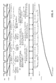
- FIG. 4 is a timing chart of the wobbling according to the first embodiment.
- FIG. 5 is a flowchart of mountain-climbing according to the first embodiment.
- FIG. 6 is a timing chart of the mountain-climbing according to the first embodiment.
- FIGS. 7A and 7B are flowcharts of wobbling according to a second embodiment.
- FIG. 8 is a timing chart of the wobbling according to the second embodiment.
- FIGS. 9A and 9B are flowcharts of wobbling according to a third embodiment.
- FIG. 10 is a timing chart of the wobbling according to the third embodiment.
- FIG. 11 is a flowchart of a focus lens driving control.
- FIG. 1 illustrates a configuration of the lens interchangeable type camera system (image-pickup system) according to the first embodiment.
- a lens unit (interchangeable lens) L 100 is attached to and detached from a camera body (or video camera body, image-pickup apparatus) C 100 , and a camera body C 100 can be mounted with the lens unit L 100 .
- a first fixed lens L 101 and a second fixed lens L 104 are lenses fixed in the lens unit L 100 .
- a magnification-varying lens L 102 is a lens configured to move in an optical axis direction of the lens unit L 100 for a magnification variation.
- a diaphragm L 103 adjusts the light intensity incident upon the image sensor C 101 .
- a focus lens L 105 is a lens that serves to correct an image plane variation according to the magnification variation and to provide focusing. As illustrated in FIG.
- the image-pickup optical system of this embodiment includes, in order from the object side, the first fixed lens L 101 , the magnification-varying lens L 102 , the diaphragm (stop) L 103 , the second fixed lens L 104 , and the focus lens L 105 .
- the configuration of the image-pickup optical system illustrated in FIG. 1 according to this embodiment is merely illustrative, and the present invention is not limited to this embodiment.
- each lens unit include one lens but may actually include one or more lenses.
- the image sensor C 101 is a photoelectric conversion element, such as a CCD sensor and a CMOS sensor, configured to photoelectrically convert an object image and to output an analogue signal.
- the image sensor C 101 may be provided one each for each of three primary colors of red (R), green (G), and blue (B).
- the CDS/AGC/AD converter C 102 samples the output of the image sensor C 101 , gain-controls and digitally converts the sampled output.
- a camera signal processor C 103 performs various image processing for an output signal from the CDS/AGC/AD converter C 102 , and generates the image.
- the camera signal processor C 103 includes an AF signal processor C 1031 .
- the AF signal processor C 1031 generates a focus signal by extracting a high-frequency component or a brightness difference component based upon the output signal from pixels of a focus detecting area in the output signal (image signal) from all pixels derived from the image sensor C 101 and the CDS/AGC/AD converter C 102 .
- the focus signal is referred to as a contrast evaluation value signal, and represents the sharpness (contrast state) of an image generated based upon the output signal from the image sensor C 101 .
- the sharpness changes according to a focus state of the image-pickup optical system and consequently, the focus signal represents the focus state of the image-pickup optical system.
- a display unit C 104 displays an image from the camera signal processor C 103 , and a recorder C 105 records an image from the camera signal processor C 103 in a recording medium, such as a magnetic tape, an optical disk, and a semiconductor memory.
- a camera microcomputer (image-pickup apparatus controller) C 106 controls the entire operation of the camera body C 100 .
- the camera microcomputer C 106 controls a focus actuator L 108 in the lens unit L 100 , which will be described later, based upon the output from the camera signal processor C 103 , and moves the focus lens L 105 in the optical axis direction.
- the camera microcomputer C 106 of the camera body provides the AF control.
- the camera AF controller C 1061 generates information on driving of the focus lens based upon the focus signal output from the camera signal processor C 103 . A detailed operation of the camera AF controller C 1061 will be described later.
- the camera microcomputer C 106 serves as a communication unit configured to communicate with the lens microcomputer L 106 , which will be described later.
- a lens microcomputer L 106 serves as a communication unit configured to transmit information to and receive information from (or communicate information with) the camera microcomputer C 106 .
- the lens microcomputer L 106 includes a lens AF controller L 1061 .
- the lens AF controller L 1061 controls focusing in accordance with a target position of the focus lens L 105 determined by the camera AF controller C 1061 .
- the lens AF controller L 1061 provides a zoom tracking control configured to move the focus lens L 105 based upon zoom tracking data (a zoom tracking cam) stored in the lens microcomputer L 106 in the magnification variation.
- the zoom tracking data is stored data on a relationship between the position of the focus lens L 105 and the magnification-varying lens L 102 for each of a plurality of focal lengths, and represents a locus of the focus lens L 105 so as to maintain the in-focus state. This configuration prevents an image plane fluctuation (blur) associated with the magnification variation.
- the zoom actuator L 107 is a zoom driving source configured to move a magnification-varying lens L 102 .
- the focus actuator L 108 is a focus driving source configured to move the focus lens L 105 .
- Each of the zoom actuator L 107 and the focus actuator L 108 includes an actuator, such as a stepping motor, a DC motor, a vibration type motor, and a voice coil motor.
- TVAF control focus control
- FIG. 2 is a flowchart of an overview of the TVAF control in the live-view display mode or a motion image-pickup mode. This procedure is mainly executed by the camera AF controller C 1061 in the camera microcomputer C 106 in accordance with a computer program. This is true of other embodiments.
- the camera microcomputer C 106 controls driving and a position of the focus lens L 105 through communications with the lens microcomputer L 106 (lens AF controller L 1061 ).
- Step 201 the camera microcomputer C 106 determines whether the current TVAF mode is a wobbling mode. If so the flow moves to the Step 202 , and if not the flow moves to Step 208 .
- Step 202 the camera microcomputer C 106 performs a wobbling operation so as to wobble the focus lens L 105 with the predetermined amplitude, and determines whether it is in-focused and if not determines which direction an in-focus point exists. A detailed operation will be described with reference to FIGS. 3 and 4 .
- Step 203 the camera microcomputer C 106 determines whether the focus lens L 105 reciprocates in the same area a predetermined number of times based upon the positional history of the focus lens L 105 as a result of the wobbling operation in the Step 202 . If so the in-focus is determined and the flow moves to Step 206 , and if not the in-focus has not yet been determined and the flow moves to Step 204 .
- the camera microcomputer C 106 determines whether it has determined that the in-focus point exists in the same direction a predetermined number of times based upon the positional history of the focus lens L 105 as a result of the wobbling operation in the Step 202 . If so, the flow moves to Step 205 for the climbing (drive) mode because the in-focus direction has been determined. If not, the flow returns to the Step 201 because the in-focus direction has not yet been determined.
- Step 206 the camera microcomputer C 106 stores a focus signal level at the in-focus position in a memory (not illustrated), and the flow moves to Step 207 for a restart determining mode.
- the restart determining mode is a mode configured to determine whether wobbling is again necessary to determine the in-focus direction. This will be described in Steps 216 and 217 , which will be described later.
- Step 208 the camera microcomputer C 106 determines whether the current TVAF mode is a mountain-climbing mode. If so the flow moves to Step 209 , and if not the flow moves to Step 213 .
- the camera microcomputer C 106 provides the mountain-climbing configured to drive the focus lens L 105 at a predetermined speed in which a value of the focus signal increases. A detailed description will be described with reference to FIGS. 5 and 6 .
- Step 210 the camera microcomputer C 106 determines whether the position of the focus lens L 105 (referred to as a “peak position” hereinafter) which provides a maximum value (a value representing the in-focus state of the image-pickup optical system) is detected by the mountain-climbing in the Step 209 .
- the peak position is detected, the flow moves to Step 211 , and if not the flow returns to the Step 201 so as to continue the mountain-climbing mode.
- the focus lens L 105 is moved to the peak position (Step 214 ) and the in-focus determining mode follows (Step 215 ) as described later.
- Step 211 the camera microcomputer C 106 sets the peak position to the target position of the focus lens L 105 . Then, the flow moves to Step 212 for the stopping mode.
- Step 213 the camera microcomputer C 106 determines whether the current TVAF mode is the stopping mode, and if so the flow moves to Step 214 , and if not the flow moves to Step 216 .
- the camera microcomputer C 106 determines whether the focus lens L 105 has returned to the peak position. If so, the flow moves to the Step 215 for the wobbling mode (in-focus determination), and if not the flow returns to the Step 201 so as to continue the stopping mode.
- the camera microcomputer C 106 compares the level of the current focus signal with the level of the focus signal held in the Step 206 , and determines whether the variation amount is larger than the predetermined amount. When the variation amount is larger than the predetermined amount, the flow moves to Step 217 for the wobbling (direction determining) mode so as to determine the in-focus direction, if not the flow returns to the Step 201 so as to continue the restart determining mode.
- the camera microcomputer C 106 sends the drive starting timing of focus lens L 105 (also referred to as “driving timing” hereafter) and reaching prediction timing to the lens microcomputer L 106 .
- the reaching prediction timing is timing at which the lens microcomputer L 106 predicts whether the focus lens L 105 can reach the target position within a predetermined time period.
- the lens microcomputer L 106 sends back to the camera microcomputer C 106 a prediction result made at the reaching prediction timing of whether the focus lens L 105 can reach the target position within the predetermined time period.
- the focus control can be made by managing both control timings.
- Step C 301 the camera microcomputer C 106 determines whether the current timing for the vertical synchronizing signal of the image accords with the predetermined timing of the lens communication with the lens microcomputer L 106 . If so, the flow moves to Step C 302 , and if not the flow returns to the Step C 301 for standing by.
- the timing of the lens communication for the vertical synchronizing signal can be arbitrarily set based upon the image signal accumulation timing of the image sensor C 101 but a delay time period to the vertical synchronizing signal needs to be constant.
- the camera microcomputer C 106 and the lens microcomputer L 106 perform a fixed-length packet communication twice in one vertical synchronizing period.
- a communication performed in Steps C 303 and L 303 will be referred to as a first communication
- a communication performed at Step C 327 and L 305 will be referred to as a second communication, as described later.
- the camera microcomputer C 106 transmits a communication request to the lens microcomputer L 106 so as to start the lens communication.
- Step L 301 the lens microcomputer L 106 determines whether it has received the communication request, which has been transmitted from the camera microcomputer C 106 in the Step C 302 . If so the flow moves to Step L 302 , and if not the flow returns to the Step L 301 for standing by.
- the lens microcomputer L 106 resets the internal timer using the start of the first lens communication as a trigger, and measures a delay time period from the start of the lens communication.
- Step L 303 the lens microcomputer L 106 transmits as a first communication a result of a reaching prediction determination and predicted lens position calculated in the last processing to the camera microcomputer C 106 .
- the content of the reaching prediction determination and predicted lens position will be described in detail later in Step L 1104 .
- the camera microcomputer C 106 receives the result of the reaching prediction determination and the predicted lens position, which have been transmitted from the lens microcomputer L 106 in the Step L 303 . If the current VD is ( 4 ) in the example illustrated in FIG. 4 , then this processing corresponds to the timing ( 4 ) of receiving the reaching prediction determination. etc.
- Step C 304 the camera microcomputer C 106 determines which of infinity driving, infinity stopping, short distance driving, and short distance stopping the current control state is. If the current control is the infinity driving, then the flow moves to Step C 305 . If the current control is the infinity stopping, then the flow moves to Step C 311 . If the current control is the short distance driving, then the flow moves to Step C 315 . If the current control is the short distance stopping, then the flow moves to Step C 321 .
- the camera microcomputer C 106 compares the level of the focus signal on the infinity side stored in the previous step C 321 with the level of the focus signal on the short distance side stored in the previous Step C 311 . If the former is larger, then the flow moves to the Step C 306 , and if not, then the flow moves to the Step C 307 . If the current VD is ( 7 ) in the example of FIG. 4 , then the focus signal ( 4 ) is compared with the focus signal ( 2 ).
- the camera microcomputer C 106 calculates, as a defocus amount on the image-pickup plane, an (image plane center) moving amount in the infinity direction of the center position that is the driving center of the focus lens L 105 .
- This defocus amount is set to a value within the depth of focus.
- the camera microcomputer C 106 calculates, as a defocus amount on the image-pickup plane, a driving amount (image plane amplitude amount, vibration amplitude amount) in the infinity direction of the center position of the focus lens L 105 . Similar to the moving amount of the center position, this defocus amount is set to a value within the depth of focus.
- the camera microcomputer C 106 calculates the drive starting timing used to actually start driving the focus lens L 105 by a defocus amount (target defocus amount) calculated in the Steps C 306 and C 307 .
- the drive staring timing is set based upon the accumulation completing timing of the image signal of the image sensor C 101 . If the current VD is ( 3 ) in the example of FIG. 4 , the timing at which the accumulation ( 2 ) of the image sensor C 101 is completed is the lens drive starting timing ( 4 ). This embodiment sets the timing at which the accumulation ( 2 ) of the image sensor C 101 is completed to the lens drive starting timing ( 4 ).
- the lens drive starting timing ( 4 ) may be determined based upon the accumulation completion timing of the focus detecting area among the output signal from all the pixels of the image sensor C 101 .
- This embodiment defines this drive starting timing as a delay time period from the start of the first communication.
- the present invention is not limited to this embodiment, and a delay time period for the vertical synchronizing signal, a delay time period may be used.
- Step C 309 the camera microcomputer C 106 calculates the reaching prediction timing used to obtain the next target defocus amount if the focus lens L 105 is driven at the drive starting timing calculated in the Step C 308 .
- a proper target defocus amount can be obtained if the focus lens L 105 reaches the target position a predetermined permissible time period after the reaching prediction timing, and the reaching prediction timing is set based upon the charge accumulation start timing of the image signal of the image sensor C 101 . If the current VD is ( 3 ) in the example of FIG. 4 , the timing the predetermined time period after the accumulation ( 4 ) of the image sensor C 101 starts is the reaching prediction timing ( 4 ).
- This embodiment sets the reaching prediction timing ( 4 ) to the timing the predetermined time period after the accumulation ( 4 ) of the image sensor C 101 starts.
- the reaching prediction timing ( 4 ) may be determined based upon the accumulation starting timing of the focus detecting area among the output signal from all the pixels of the image sensor C 101 .
- This embodiment defines this reaching prediction timing as a delay time period from the start of the first communication.
- the present invention is not limited to this embodiment, and the reaching prediction timing may be defined as a delay time period from a vertical synchronizing signal.
- Step C 310 the camera microcomputer C 106 sets the next control state to the infinite stopping state.
- the camera microcomputer C 106 obtains a focus signal and stores the signal as information obtained when the focus lens L 105 stops at the short distance side in Step C 311 .
- the obtained signal is correlated with a focus signal generated from the image signal stored when the focus lens L 105 is located at the position stored in the Step C 323 at previous time.
- the current VD is ( 4 ) in the example of FIG. 4
- the obtainable focus signal is a signal generated from the image signal stored with VD( 2 ) when the focus lens L 105 stops on the short distance side.
- Step C 312 the flow of the camera microcomputer C 106 moves to the Step C 313 when the just previous result of the reaching prediction determination received in the Step C 303 denotes reachable. If not, the flow moves to Step C 325 . If it is predicted as being unreachable the last time, the focus lens L 105 is currently driving and the next obtainable focus signal is unlikely to obtain the proper defocus amount. It is thus necessary to delay a cycle of the TVAF control so as to avoid the malfunction.
- the camera microcomputer C 106 recognizes that the focus lens L 105 has reached the target position and stores the current position.
- the stored focus position is correlated with the focus signal obtained in the step C 321 , which will be described later.
- the camera microcomputer C 106 sets the next control state to the short distance driving state.
- the camera microcomputer C 106 in the Step C 315 compares the level of the focus signal on the short distance side stored in the last step C 311 with the level of the focus signal on the infinity side stored in the last Step C 321 . If the former is larger, then the flow moves to the Step C 316 , and if not, then the flow moves to the Step C 317 . If the current VD is ( 5 ) in the example of FIG. 4 , then the focus signal ( 2 ) is compared with a focus signal ( 0 ) (not illustrated).
- the camera microcomputer C 106 calculates, as a defocus amount on the image-pickup plane, an (image plane center) moving amount in the short distance direction of the center position that is the driving center of the focus lens L 105 .
- This defocus amount is set to a value within the depth of focus.
- the camera microcomputer C 106 calculates, as a defocus amount on the image-pickup plane, a driving amount (image plane amplitude amount) in the short distance direction of the center position of the focus lens L 105 . Similar to the moving amount of the center position, this defocus amount is set to a value within the depth of focus.
- the camera microcomputer C 106 calculates the drive starting timing used to actually start driving the focus lens L 105 .
- the drive starting timing is set based upon the accumulation completing timing of the image signal of the image sensor C 101 . If the current VD is ( 5 ) in the example of FIG. 4 , the lens drive starting timing ( 6 ) is timing at which the accumulation ( 4 ) of the image sensor C 101 is completed. This embodiment sets the lens drive starting timing ( 6 ) to timing at which the accumulation ( 4 ) of the image sensor C 101 is completed. However, the lens drive starting timing ( 6 ) may be determined based upon the accumulation completing timing of the focus detecting area among the output signal of all pixels in the image sensor C 101 . This embodiment defines this drive starting timing as a delay time period from the start of the first communication. However, the present invention is not limited to this embodiment, and the drive starting timing may be defined as a delay time period from the vertical synchronizing signal, etc.
- Step C 319 the camera microcomputer C 106 calculates the reaching predicted timing used to obtain the next target defocus amount, when the focus lens L 105 is driven at the drive starting timing calculated in the Step C 318 .
- the reaching prediction timing is set based upon the charge accumulation start timing of the image signal of the image sensor C 101 . If the current VD is ( 5 ) in the example of FIG. 4 , the reaching prediction timing ( 6 ) is the predetermined time period after the accumulation ( 6 ) of the image sensor C 101 starts. This embodiment sets the reaching prediction timing ( 6 ) to the predetermined time period after the accumulation ( 6 ) of the image sensor C 101 starts.
- the reaching prediction timing ( 6 ) may be determined based upon the accumulation start timing of the focus detection area among the output signal in all pixels of the image sensor C 101 . According to this embodiment, this reaching prediction timing is defined by the delay time period from the start of the first communication. However, the present invention is not limited to this embodiment, and the reaching prediction timing may be defined as a delay time period from a vertical synchronizing signal.
- Step C 320 the camera microcomputer C 106 sets the next control state to the short distance stopping state.
- the camera microcomputer C 106 obtains a focus signal and stores the signal as information when the focus lens L 105 stops at the infinity side in Step C 321 .
- the obtained signal is correlated with a focus signal generated from the image signal stored when the focus lens L 105 is located at the position stored in the Step C 313 last time. If the current VD is ( 6 ) in the example of FIG. 4 , the obtainable focus signal is a signal generated from the image signal stored with VD( 4 ) when the focus lens L 105 stops on the infinity side.
- Step C 322 the camera microcomputer C 106 moves to the Step C 323 when the last result of the reaching prediction determination received in the Step C 303 denotes reachable. If not, the flow moves to Step C 325 . If it is predicted as being unreachable last time, the focus lens L 105 is currently driving and the next obtainable focus signal is unlikely to obtain the proper defocus amount. It is thus necessary to delay a cycle of the TVAF control so as to avoid the malfunction.
- the camera microcomputer C 106 recognizes that the focus lens L 105 has reached the target position and stores the current position.
- the stored focus position is correlated with the focus signal obtained in the next step C 311 .
- the camera microcomputer C 106 sets the next control state to the infinity driving state.
- the current driving command is a command of directly or indirectly designating the target position, and thus command mode is set to a position designating command.
- this command mode includes two types, i.e., a position designating command and a direction designating command, which will be described later, but may include a stopping command, an invalid command, etc.
- the camera microcomputer C 106 can set one command mode among the position designating command, the direction designating command, the stopping command, and the invalid command.
- the position designating command is a first control that provides control by designating a driving target position of the focus lens
- the direction designating command is a second control that provides control by designating the driving direction of the focus lens.
- Step C 326 the camera microcomputer C 106 again transmits the communication request to the lens microcomputer L 106 and starts the lens communication.
- the lens microcomputer L 106 determines whether the lens microcomputer L 106 has received the communication request, which has been transmitted from the camera microcomputer C 106 in the step C 326 . If so the flow moves to the Step L 305 , and if not the flow returns to the Step L 304 for standing by.
- the camera microcomputer C 106 transmits information on driving of the focus lens L 105 as the second communication to the lens microcomputer L 106 .
- the information on driving of the focus lens L 105 contains a command mode set in the Step C 325 . It also contains the target defocus amount, such as the image plane amplitude amount and the image plane center moving amount calculated in the Steps C 306 , C 307 , C 316 , and C 317 . It also contains drive starting timing calculated in the Step C 308 or C 318 , and the reaching prediction timing calculated in the Step C 309 or C 319 (information on driving time of the focus lens). If the current VD is ( 5 ) in the example of FIG.
- this processing corresponds to transmission timing of the command mode ( 6 ), the target defocus amount ( 6 ), etc.
- the driving speed which will be described later, is set by the lens microcomputer L 106 , and an arbitrary numerical value is set to a data area used to set driving speed data (second data area).
- driving speed data (the driving speed ( 6 )) is not used for the lens unit.
- the arbitrary numerical value is set to the data area of the driving speed, although it is not used by the lens unit, because the camera microcomputer C 106 and the lens microcomputer L 106 provide a fixed-length packet communication.
- the lens microcomputer L 106 receives information on the driving of the focus lens L 105 , such as the command mode and the target defocus amount, which has been transmitted from the camera microcomputer C 106 in the Step C 327 . Thereafter, the lens microcomputer L 106 provides driving control over the focus lens based upon the received information, as described later.
- the camera microcomputer C 106 determines whether the focus lens L 105 has reciprocated in the same area a predetermined number of times (NB). When determining that the focus lens L 105 has reciprocated in the same area the predetermined number of times (NB), the camera microcomputer C 106 calculates an in-focus position based upon the past lens position information and determines the in-focus. Then, the flow moves to the restart determining mode because the in-focus has been determined in the Step 203 in FIG. 2 .
- NB predetermined number of times
- the camera microcomputer C 106 determines whether the same in-focus direction has been detected a predetermined number of times (NB). If the same in-focus direction is detected the predetermined number of times (NB), the camera microcomputer C 106 determines the in-focus direction. In this case, the Step 204 moves to the Step 205 in FIG. 2 , the in-focus direction is determined, and the flow moves to the mountain-climbing mode.
- Step C 501 in FIG. 5 the camera microcomputer C 106 determines whether the current timing to the vertical synchronizing signal of the image accords with the predetermined timing for the lens communication. If so the flow moves to Step C 502 and if not the flow returns to Step C 501 so as to wait the accordance.
- the timing of the lens communication can be arbitrarily set based upon the accumulation timing of the image signal of the image sensor C 101 but a delay time period to the vertical synchronizing signal needs to be constant.
- the camera microcomputer C 106 and the lens microcomputer L 106 perform a fixed-length packet communication twice in one vertical synchronizing period.
- a communication performed in Steps C 503 and L 503 will be referred to as a first communication
- a communication performed at Step C 514 and L 505 will be referred to as a second communication, as described later.
- the camera microcomputer C 106 transmits a communication request to the lens microcomputer L 106 and starts the lens communication.
- Step L 501 the lens microcomputer L 106 determines whether it has received the communication request, which has been transmitted from the camera microcomputer C 106 in the Step C 502 . If so the flow moves to Step L 502 , and if not the flow returns to the Step L 501 for standing by.
- the lens microcomputer L 106 resets the internal timer using the start of the first lens communication as a trigger, and measures a delay time period from the start of the lens communication.
- Step L 503 the lens microcomputer L 106 transmits as a first communication a result of a reaching prediction determination and a predicted lens position calculated in the last processing to the camera microcomputer C 106 .
- this embodiment conveniently transmits the result of the reaching prediction determination due to the fixed-length packet communication, the result of the reaching prediction result is not actually used for the camera microcomputer C 106 because the camera microcomputer C 106 does not specifically designate a target position in the mountain-climbing, as described later.
- the content of the predicted lens position will be described in detail later in Step L 1108 .
- the camera microcomputer C 106 receives the result of the reaching prediction determination and the predicted lens position, which have been transmitted from the lens microcomputer L 106 in the Step L 503 .
- the received prediction lens portion is correlated with the focus signal obtained in the next Step C 504 , which will be described later. If the current VD is ( 4 ) in the example illustrated in FIG. 6 , then the processing corresponds to the timing ( 3 ) of receiving the reaching prediction determination, etc.
- Step C 504 the camera microcomputer C 106 obtains a focus signal, and stores it as the driving history of the focus lens L 105 .
- the obtained focus signal is correlated with the focus signal generated from the image signal accumulated when the focus lens L 105 is located at the position in the Step C 503 last time. If the current VD is ( 5 ) in the example of FIG. 6 , then the available focus signal is generated from the image signal accumulated in the VD ( 3 ) when the focus lens L 105 is driven.
- Step C 505 the camera microcomputer C 106 compares the level of the focus signal currently obtained in Step C 504 with the level of the focus signal previously obtained in Step C 504 . If the former is larger, then the flow moves to the Step C 506 , and if not, then the flow moves to the Step C 507 .
- Step C 506 the camera microcomputer C 106 sets the next driving direction to the same direction as the current direction because the focus signal is increasing.
- This embodiment designates a driving direction utilizing data area (first data area) used to set data of the image plane amplitude amount in the wobbling. More specifically, the driving direction is designated based upon code information of a numerical value set to the data area. In this embodiment, the image plane amplitude amount set in the wobbling and the driving direction set in the mountain-climbing are set to the corresponding data area (first data area). Other than this method, the driving direction may be designated by separately preparing the communication data.
- Step C 507 the camera microcomputer C 106 determines whether the peak of the focus signal has already found. If so the flow moves to Step C 509 , and if not the flow moves to Step C 508 .
- Step C 508 the camera microcomputer C 106 sets the next driving direction to a direction reverse to the current direction because the focus signal is decreasing although the peak of the focus signal has not yet been found.
- this embodiment designates the driving direction utilizing data area (first data area) used to set data of the image plane amplitude amount in the wobbling and code information of the numerical value used to set the data area.
- Step C 509 the camera microcomputer C 106 determines the peak of the focus signal. In this case, the flow moves to the step 210 in FIG. 2 then to Step 211 because the peak position has been found, and ends the mountain-climbing.
- Step C 510 the camera microcomputer C 106 calculates the driving speed of the focus lens L 105 as the focus moving speed on the image plane. This driving speed is set so that the focus moving amount can fall within the depth of focus per a time period necessary to obtain one focus signal.
- Step C 511 the camera microcomputer C 106 calculates the timing for the reaching prediction of the focus lens L 105 obtained in the step C 503 .
- the camera microcomputer C 106 sets the timing at which the lens position is predicted. This timing is based upon the charge accumulation start timing of the image signal of the image sensor C 101 in the Steps C 309 and C 319 in the wobbling.
- the reaching prediction timing is set based upon the charge accumulation center timing of the image signal of the image sensor C 101 in the Step C 511 . If the current VD is ( 3 ) in the example of FIG. 6 , the center timing in the necessary accumulation ( 3 ) period for the image sensor C 101 becomes the lens reaching prediction timing ( 3 ).
- This embodiment defines the reaching prediction timing as a delay time period from the start of the first lens communication.
- the present invention is not limited to this embodiment, and the reaching prediction timing may be defined as a delay time period to the vertical synchronizing signal, etc.
- Step C 512 the command mode is set to the direction designating command so as to inform the lens microcomputer L 106 of the command of designating the driving direction.
- the camera microcomputer C 106 again transmits a communication request to the lens microcomputer L 106 , and starts the lens communication.
- Step L 504 the lens microcomputer L 106 determines whether the lens microcomputer L 106 has received the communication request, which has been transmitted from the camera microcomputer C 106 in the Step C 513 . If so the flow moves to the Step L 505 , and if not the flow returns to the Step L 504 for standing by.
- the camera microcomputer C 106 transmits information on driving of the focus lens L 105 as the second communication to the lens microcomputer L 106 .
- the information on driving of the focus lens L 105 contains the command mode set in the step C 512 . It also contains the driving direction etc. set in the Step C 506 or C 508 . It also contains the driving speed calculated in the Step C 510 , the reaching prediction timing calculated in the Step C 511 , etc. If the current VD is ( 3 ) in the example of FIG. 6 , this processing corresponds to the transmission timing of the command mode ( 3 ), the driving direction ( 3 ), etc.
- the focus lens L 105 is always driven, and it is unnecessary for the camera microcomputer C 106 to designate the drive starting timing.
- the camera microcomputer C 106 sets an arbitrary numerical value to the data area, but the lens microcomputer L 106 invalidates the set numerical value as described later and does not use it to control driving of the focus lens L 105 .
- Step L 505 the lens microcomputer L 106 receives information on driving of the focus lens L 105 , such as a command mode and a driving direction, sent from the camera microcomputer C 106 in the Step C 514 . Thereafter, the lens microcomputer L 106 controls driving of the focus lens as described later on the basis of the received information.
- Step 1101 the lens microcomputer L 106 determines whether the command mode received in Steps L 305 or L 505 is the position designating command. If so the flow moves to the Step 1102 , and if not the flow moves to the Step 1106 .
- the lens microcomputer L 106 calculates an actual drive amount (actual moving amount) of the focus lens L 105 , and sets the target position.
- the actual drive amount is calculated by considering the current focus position sensitivity so as to obtain a target focus amount received in the step L 305 .
- the lens microcomputer L 106 calculates a driving speed of the focus lens L 105 in accordance with the actual drive amount found in the Step 1102 .
- the driving speed is calculated based upon the characteristic of the focus actuator L 108 by considering the influence of noises and overshooting in the operation of the focus lens L 105 .
- the lens microcomputer L 106 can vary the driving speed of the focus lens L 105 at arbitrary timing.
- Step 1104 the lens microcomputer L 106 predicts a position which the focus lens L 105 reaches when it is driven by the driving speed calculated in the Step 1103 from the drive starting timing to the reaching prediction timing received in the Step L 305 .
- the lens microcomputer L 106 predicts the position of the focus lens L 105 at the reaching prediction timing received in the Step L 305 when the focus lens is driven at the driving speed calculated in the Step 1103 at the drive starting timing received in the step L 305 .
- the lens microcomputer L 106 determines whether the focus lens can reach the target position within a predetermined permissible time period after the reaching prediction timing received in the Step L 305 . It is determined whether the target defocus amount requested by the camera microcomputer C 106 can be obtained.
- the result of the reaching prediction determination is sent from the lens microcomputer L 106 to the camera microcomputer C 106 in the next Step L 303 .
- Step 1105 the lens microcomputer L 106 determines whether the delay time from the starting time of the first lens communication accords with the drive starting timing received in the Step L 305 based upon a value of the internal timer reset in the Step L 302 . If the delay time accords, the flow moves to the Step 1109 and if not, the flow returns to the Step 1105 for standing by.
- lens microcomputer L 106 sets the target position set in the Step 1102 and the driving speed calculated in the Step 1103 to the focus actuator L 108 , and actually drives the focus lens L 105 . If the current VD is ( 5 ) in the example of FIG. 4 , this processing corresponds to the timing of focus ( 6 ) driving.
- Step 1106 the lens microcomputer L 106 sets the target position of the focus lens L 105 .
- the camera microcomputer C 106 does not designate a specific target position in the direction designating command. Therefore, the lens microcomputer L 106 can freely set an actual target position as long as the driving direction received in the Step L 505 can be guaranteed.
- the lens microcomputer L 106 calculates the driving speed of the focus lens L 105 .
- the driving speed is calculated by converting the driving speed on the image-pickup plane received in the Step L 505 into an actual lens driving speed by considering the current focus position sensitivity.
- Step 1108 the lens microcomputer L 106 predicts the position of the focus lens L 105 at the reaching prediction timing received in the Step L 505 when the focus lens L 105 is driven by the driving speed calculated in the Step 1107 .
- the reaching prediction result is transmitted from the lens microcomputer L 106 to the camera microcomputer C 106 in the next Step L 503 .
- Step 1109 the lens microcomputer L 106 sets the target position set in the Step 1106 and the driving speed calculated in the Step 1107 to the focus actuator L 108 , and actually drives the focus lens L 105 .
- the current VD is ( 3 ) in the example of FIG. 6
- this processing corresponds to the timing of focus ( 3 ) driving timing. Since it is necessary to strictly manage the timing of driving and halting the focus lens L 105 in wobbling of the position designating command, the camera microcomputer C 106 needs to designate the drive starting timing. On the other hand, the focus lens L 105 is always driven in the mountain-climbing of the direction designating command, and it is unnecessary to newly designate the drive starting timing.
- the lens microcomputer L 106 switches validity/invalidity of the information set to a specific data area in accordance with the received command mode. More specifically, the lens microcomputer L 106 controls driving of the focus lens L 105 by using information set to the data area (third data area) of the drive starting timing for the position designating command, and does not utilize information set to the data area to control driving of the focus lens L 105 in the direction designating command.
- This configuration enables the TVAF control command corresponding to each of wobbling and mountain-climbing to be communicated without changing a communication format in accordance with the command mode.
- This embodiment moves the focus lens L 105 by repeating the restart determination, wobbling, mountain-climbing, stopping, wobbling and restart determination in the TVAF control in this order. Thereby, an in-focus state can be maintained so that the focus signal can always have a maximum level.
- the camera body sends information on driving of the focus lens L 105 to the lens unit, and the lens unit sends information on the position of the focus lens L 105 to the camera body.
- the camera body can always recognize a cycle of the TVAF control in advance as in the lens integrated type camera even when lens units to be attached to the camera body have different optical characteristics.
- the camera body can provide excellent TVAF control.
- the camera body sends the reaching prediction timing to the lens unit.
- the lens unit predicts whether the focus lens can reach the target position at the reaching prediction timing and sends the reaching prediction result back to the camera body.
- the lens unit predicts the actual driving amount of the focus lens at the reaching prediction timing received from the camera body, converts it into the defocus amount on the image-pickup plane, and sends the defocus amount predicted result back to the camera body.
- the structure of the lens exchangeable type camera system according to this embodiment is similar to that of the first embodiment ( FIG. 1 ).
- An overall flow of the TVAF control is similar to that of the first embodiment ( FIG. 2 ).
- Step C 701 the camera microcomputer C 106 determines whether the current timing for the vertical synchronizing signal of the image accords with the predetermined timing of the lens communication with the lens microcomputer L 106 . If so the flow moves to Step C 702 , and if not the flow returns to the Step C 701 for standing by.
- the timing of the lens communication for the vertical synchronizing signal can be arbitrarily set based upon the image signal accumulation timing of the image sensor C 101 but a delay time period to the vertical synchronizing signal needs to be constant.
- the camera microcomputer C 106 and the lens microcomputer L 106 perform a fixed-length packet communication twice in one vertical synchronizing period.
- a communication performed at Steps C 703 and L 703 will be referred to as a first communication
- a communication performed at Step C 727 and L 705 will be referred to as a second communication, as described later.
- the camera microcomputer C 106 transmits a communication request to the lens microcomputer L 106 and starts the lens communication.
- Step L 701 the lens microcomputer L 106 determines whether it has received the communication request, which has been transmitted from the camera microcomputer C 106 in the Step C 702 . If so the flow moves to Step L 702 , and if not the flow returns to the Step L 701 for standing by.
- the lens microcomputer L 106 resets the internal timer using the start of the first lens communication as a trigger, and measures a delay time period from the start of the lens communication.
- Step L 703 the lens microcomputer L 106 transmits as a first communication a result of a reaching defocus amount and a prediction lens position calculated in the last processing to the camera microcomputer C 106 .
- the content of the reaching defocus amount and predicted lens position will be described in detail later in Step L 1104 .
- the camera microcomputer C 106 receives the result of the reaching prediction determination and the predicted lens position, which have been transmitted from the lens microcomputer L 106 in the Step L 703 . If the current VD is ( 4 ) in the example illustrated in FIG. 8 , then the processing corresponds to the timing ( 4 ) of receiving the reaching prediction, etc.
- Step C 704 the camera microcomputer C 106 determines which of infinity driving, infinity stopping, short distance driving, and short distance stopping the current control state is. If the current control is the infinity driving, then the flow moves to Step C 705 . If the current control is the infinity stopping, then the flow moves to Step C 711 . If the current control is the short distance driving, then the flow moves to Step C 715 . If the current control is the short distance stopping, then the flow moves to Step C 721 .
- the camera microcomputer C 106 compares the level of the focus signal on the infinity side stored in the last step C 721 with the level of the focus signal on the short distance side stored in the last Step C 711 . If the former is larger, then the flow moves to the Step C 706 , and if not, then the flow moves to the Step C 707 . If the current VD is ( 7 ) in the example of FIG. 8 , then the focus signal ( 4 ) is compared with the focus signal ( 2 ).
- the camera microcomputer C 106 calculates, as a defocus amount on the image-pickup plane, an (image plane center) moving amount in the infinity direction of the center position that is the driving center of the focus lens L 105 .
- This defocus amount is set to a value within the depth of focus.
- the camera microcomputer C 106 calculates, as a defocus amount on the image-pickup plane, a driving amount (image plane amplitude amount) in the infinity direction of the center position of the focus lens L 105 . Similar to the moving amount of the center position, this defocus amount is set to a value within the depth of focus.
- the camera microcomputer C 106 calculates the drive starting timing used to actually drive the focus lens L 105 by a (target) defocus amount calculated in the Steps C 706 and C 707 .
- the drive staring timing is set based upon the accumulation completing timing of the image signal of the image sensor C 101 . If the current VD is ( 3 ) in the example of FIG. 8 , the timing at which the accumulation ( 2 ) of the image sensor C 101 is completed is the lens drive starting timing ( 4 ). This embodiment sets the timing at which the accumulation ( 2 ) of the image sensor C 101 is completed to the lens drive starting timing ( 4 ).
- the lens drive starting timing ( 4 ) may be determined in accordance with the accumulation completion timing of the focus detecting area among the output signal in all pixels of the image sensor C 101 .
- This embodiment defines this drive starting timing as a delay time period from the start of the first communication.
- the present invention is not limited to this embodiment, and the drive starting timing may be defined as a delay time period to the vertical synchronizing signal, etc.
- Step C 709 the camera microcomputer C 106 calculates the reaching prediction timing used to obtain the next target defocus amount when the focus lens L 105 is driven at the drive starting timing calculated in the Step C 708 .
- a proper target defocus amount can be obtained if the focus lens L 105 reaches the target position a predetermined permissible time period after the reaching prediction timing, and the reaching prediction timing is set based upon the charge accumulation start timing of the image signal of the image sensor C 101 . If the current VD is ( 3 ) in the example of FIG. 8 , the reaching prediction timing ( 4 ) is the predetermined time period after the accumulation ( 4 ) of the image sensor C 101 starts.
- This embodiment sets the reaching prediction timing ( 4 ) to the predetermined time period after the accumulation ( 4 ) of the image sensor C 101 starts.
- the reaching prediction timing ( 4 ) may be determined based upon the accumulation start timing of the focus detecting area among the output signal in all pixels of the image sensor C 101 .
- this reaching prediction timing is defined as the delay time period from the start of the first communication.
- the present invention is not limited to this embodiment, and the reaching prediction timing may be defined as a delay time period from a vertical synchronizing signal, etc.
- Step C 710 the camera microcomputer C 106 sets the next control state to the infinite stopping state.
- the camera microcomputer C 106 obtains a focus signal and stores the signal as information obtained when the focus lens L 105 stops on the short distance side in Step C 711 .
- the obtained signal is correlated with a focus signal generated from the image signal accumulated when the focus lens L 105 is previously located at the position stored in the Step C 723 , which will be described later.
- the available focus signal is a signal generated from the image signal accumulated with VD( 2 ), when the focus lens L 105 stops on the short distance side.
- the camera microcomputer C 106 determines whether the last result of the predicted defocus amount received in the Step C 703 accords with the target defocus amount designated in the Steps C 706 and C 707 (reaching prediction determination). In other words, the camera microcomputer C 106 determines whether the desired defocus amount has been available. If so the flow moves to the Step C 713 , and if not the flow moves to the Step C 725 . If the last prediction is non-accordance, the focus lens L 105 is currently driving and the next available focus signal is unlikely to obtain the proper defocus amount. It is therefore necessary to delay a cycle of the TVAF control so as to avoid the malfunction.
- Step C 713 the camera microcomputer C 106 recognizes that the focus lens L 105 has reached the target position and stores the current position.
- the stored focus position is correlated with the focus signal obtained in Step C 721 , which will be described later.
- Step C 714 the camera microcomputer C 106 sets the next control state to the short distance driving state.
- the camera microcomputer C 106 in the Step C 715 compares the level of the focus signal on the short distance side stored in the last step C 711 with the level of the focus signal on the infinity side stored in the last Step C 721 . If the former is larger, then the flow moves to the Step C 716 , and if not, then the flow moves to the Step C 717 . If the current VD is ( 5 ) in the example of FIG. 8 , then the focus signal ( 2 ) is compared with the focus signal ( 0 ) (not illustrated).
- the camera microcomputer C 106 calculates, as a defocus amount on the image-pickup plane, an (image plane center) moving amount in the short distance direction of the center position that is the driving center of the focus lens L 105 .
- This defocus amount is set to a value within the depth of focus.
- the camera microcomputer C 106 calculates, as a defocus amount on the image-pickup plane, a driving amount (image plane amplitude amount) in the short distance direction of the center position of the focus lens L 105 . Similar to the moving amount of the center position, this defocus amount is set to a value within the depth of focus.
- the camera microcomputer C 106 calculates the drive starting timing used to actually drive the focus lens L 105 .
- the drive staring timing is set based upon the accumulation completing timing of an image signal of the image sensor C 101 . If the current VD is ( 5 ) in the example of FIG. 8 , the lens drive starting timing ( 6 ) is timing at which the accumulation ( 4 ) of the image sensor C 101 is completed. In this embodiment, the lens drive starting timing ( 6 ) is timing at which the accumulation ( 4 ) of the image sensor C 101 is completed. However, the lens drive starting timing ( 6 ) may be determined based upon the accumulation completion timing of the focus detecting area among the output signal from all pixels in the image sensor C 101 . This embodiment defines this lens drive starting timing as a delay time period from the start of the first communication. However, the present invention is not limited to this embodiment, and the lens drive starting timing may be defined as a delay time period to the vertical synchronizing signal, etc.
- Step C 719 the camera microcomputer C 106 calculates the reaching prediction timing used to obtain the next target defocus amount when the focus lens L 105 is driven at the drive starting timing calculated in the Step C 718 .
- the reaching prediction timing is set based upon the charge accumulation start timing of the image signal of the image sensor C 101 .
- the reaching prediction timing ( 6 ) is the predetermined time period after the accumulation ( 6 ) of the image sensor C 101 starts.
- the reaching prediction timing ( 6 ) is the predetermined time period after the accumulation ( 6 ) of the image sensor C 101 starts.
- the reaching prediction timing ( 6 ) may be determined based upon the accumulation start timing of the focus detecting area among the output signal from all pixels of the image sensor C 101 . According to this embodiment, this reaching prediction timing is defined as a delay time period from the start of the first communication. However, the present invention is not limited to this embodiment, and the reaching prediction timing may be defined as a delay time period to a vertical synchronizing signal, etc.
- Step C 720 the camera microcomputer C 106 sets the next control state to the short distance stopping state.
- the camera microcomputer C 106 obtains a focus signal and stores the signal as information obtained when the focus lens L 105 stops at the infinity side in Step C 721 .
- the obtained signal is correlated with a focus signal generated from the image signal accumulated when the focus lens L 105 is located at the position stored in the last Step C 713 . If the current VD is ( 6 ) in the example of FIG. 8 , the available focus signal is a signal generated from the image signal stored with VD( 4 ), when the focus lens L 105 stops on the infinity side.
- the camera microcomputer C 106 determines whether the last result of the predicted defocus amount received in the Step C 703 accords with the target defocus amount designated by the Steps C 716 and C 717 (reaching prediction determination). In other words, the camera microcomputer C 106 determines whether the desired defocus amount is available. If so the flow moves to the Step C 723 , and if not the flow moves to Step C 725 . If the last prediction is non-accordance, the focus lens L 105 is currently driving and the next available focus signal is unlikely to obtain the proper defocus amount. It is therefore necessary to delay a cycle of the TVAF control so as to avoid the malfunction.
- the camera microcomputer C 106 recognizes that the focus lens L 105 has reached the target position and stores the current position.
- the stored focus position is correlated with the focus signal obtained in the step C 711 .
- the camera microcomputer C 106 sets the next control state to the infinity driving state.
- the current driving command is a command of directly or indirectly designating the target position, and thus command mode is set to a position designating command.
- this command mode includes two types, i.e., the position designating command and the direction designating command, which will be described later, but may include a stopping command, an invalid command, etc.
- the camera microcomputer C 106 can set one command mode among the position designating command, the direction designating command, the stopping command, and the valid command.
- the position designating command is a first control that provides control by designating a driving target position of the focus lens
- the direction designating command is a second control that provides control by designating a driving direction of the focus lens.
- Step C 726 the camera microcomputer C 106 again transmits the communication request to the lens microcomputer L 106 and starts the lens communication.
- the lens microcomputer L 106 determines whether the lens microcomputer L 106 has received the communication request, which has been transmitted from the camera microcomputer C 106 in the Step C 726 . If so the flow moves to the Step L 705 , and if not the flow returns to the Step L 704 for standing by.
- the camera microcomputer C 106 transmits information on driving of the focus lens L 105 as the second communication to the lens microcomputer L 106 .
- the information on driving of the focus lens L 105 contains a command mode set in the Step C 725 . It also contains a target defocus amount calculated in the Steps C 706 , C 707 , C 716 , and C 717 , such as the image plane amplitude amount and the image plane center moving amount. It also contains the drive starting timing calculated in the Step C 708 or C 718 and the reaching prediction timing calculated in the Step C 709 or C 719 . If the current VD is ( 5 ) in the example of FIG.
- this processing corresponds to the transmission timing of the command mode ( 6 ) and the target defocus amount ( 6 ).
- the lens microcomputer L 106 sets the driving speed, and thus sets an arbitrary numerical value to the data area (second data area) used to set the driving speed data.
- data set to the data area of the driving speed (the driving speed ( 6 )) is not used for the lens unit.
- the arbitrary numerical value is set to the data area of the driving speed, although it is not used by the lens unit, because the camera microcomputer C 106 and the lens microcomputer L 106 provide a fixed-length packet communication.
- the lens microcomputer L 106 receives information on the driving of the focus lens, such as the command mode and the target defocus amount, transmitted from the camera microcomputer C 106 in the Step C 727 . Thereafter, the lens microcomputer L 106 provides driving control of the focus lens based upon the received information, as described later.
- the camera microcomputer C 106 determines whether the focus lens L 105 has reciprocated in the same area a predetermined number of times (NB). When determining that the focus lens L 105 has reciprocated in the same area the predetermined number of times (NB), the camera microcomputer C 106 calculates an in-focus position based upon the past lens position information and determines the in-focus. Then, the flow moves to the restart determining mode because the in-focus has been determined in the Step 203 in FIG. 2 .
- NB predetermined number of times
- the camera microcomputer C 106 determines whether the same in-focus has been detected a predetermined number of times (NB). If the in-focus direction is detected the predetermined number of times (NB), the camera microcomputer C 106 determines that the in-focus direction. In this case, the Step 204 moves to the Step 205 in FIG. 2 , the in-focus direction is determined, and the flow moves to the mountain-climbing mode.
- the control flow of the camera microcomputer C 106 and the lens microcomputer L 106 in the mountain-climbing in the Step 209 in FIG. 2 is the same as that in the first embodiment ( FIGS. 5 and 6 ).
- the control flow of driving the focus lens by the lens microcomputer L 106 after the Step L 705 in FIG. 7B and the Step L 505 in FIG. 5 is the same as that of the first embodiment ( FIG. 11 ).
- the content of the Step 1104 of the above FIG. 11 will be read as follows: “by comparing the predicted position of the focus lens L 105 with the target position set in the Step 1102 , the lens microcomputer L 106 determines whether the focus lens can reach the target position a predetermined permissible time period after the reaching prediction timing received in the Step L 305 .
- the result of the reaching prediction determination is sent from the lens microcomputer L 106 to the camera microcomputer C 106 in the next Step L 303 .” is replaced with “it is determined how large the defocus amount is on the image plane corresponding to the predicted position of the focus lens L 105 .
- the result of the predicted defocus amount is sent from the lens microcomputer L 106 to the camera microcomputer C 106 in the next Step L 703 .”
- the lens microcomputer L 106 switches validity/invalidity of the information set to a specific data area in accordance with the received command mode. More specifically, the lens microcomputer L 106 controls driving of the focus lens L 105 by using information set to the data area (third data area) of the drive starting timing for the position designating command, and does not use information set to the data area to control driving of the focus lens L 105 in the direction designating command.
- This configuration enables the TVAF control command corresponding to each of wobbling and mountain-climbing to be communicated without changing a communication format in accordance with the command mode.
- This embodiment moves the focus lens L 105 by repeating the restart determination, wobbling, mountain-climbing, stopping, wobbling and restart determination in the TVAF control in this order. Thereby, an in-focus state can be maintained so that the focus signal can always have a maximum level.
- the camera body sends information on driving the focus lens L 105 to the lens unit, and the lens unit sends information on the position of the focus lens L 105 from the lens unit to the camera body.
- the camera body can always recognize a cycle of the TVAF control in advance as in the lens integrated type camera even when lens units to be attached to the camera body have different optical characteristics.
- the camera body can provide excellent TVAF control.
- the camera body sends the reaching prediction timing to the lens unit.
- the lens unit predicts whether the focus lens can reach the target position at the reaching prediction timing and sends the reaching prediction result back to the camera body.
- the lens unit predicts the actual driving amount of the focus lens at the reaching prediction timing received from the camera body, converts it into the defocus amount on the image-pickup plane, and sends the defocus amount predicted result back to the camera body.
- the lens unit sends a time period necessary for the focus lens to reach the target position back to the camera body.
- the structure of the lens exchangeable type camera system according to this embodiment is similar to that of the first embodiment ( FIG. 1 ).
- An overall flow of the TVAF control is similar to that of the first embodiment ( FIG. 2 ).
- Step C 901 the camera microcomputer C 106 determines whether the current timing for the vertical synchronizing signal of the image accords with the predetermined timing of the lens communication with the lens microcomputer L 106 . If so the flow moves to Step C 902 , and if not the flow returns to the Step C 901 for standing by.
- the timing of the lens communication for the vertical synchronizing signal can be arbitrarily set based upon the image signal accumulation timing of the image sensor C 101 but a delay time period to the vertical synchronizing signal needs to be constant.
- the camera microcomputer C 106 and the lens microcomputer L 106 perform a fixed-length packet communication twice in one vertical synchronizing period.
- a communication performed in Steps C 903 and L 903 is referred to as a first communication
- a communication performed at Step C 927 and L 905 is referred to as a second communication, as described later.
- the camera microcomputer C 106 transmits a communication request to the lens microcomputer L 106 and starts the lens communication.
- Step L 901 the lens microcomputer L 106 determines whether it has received the communication request, which has been transmitted from the camera microcomputer C 106 in the Step C 902 . If so the flow moves to Step L 902 , and if not the flow returns to the Step L 901 for standing by.
- the lens microcomputer L 106 resets the internal timer using the start of the first lens communication as a trigger, and measures a delay time period from the start of the lens communication.
- Step L 903 the lens microcomputer L 106 transmits as a first communication a result of a predicted reaching time and predicted lens position calculated in the last processing to the camera microcomputer C 106 .
- the content of the reaching defocus amount and prediction lens position will be described in detail later in Step L 1104 .
- the camera microcomputer C 106 receives the result of the predicted reaching time and the predicted lens position, which have been transmitted from the lens microcomputer L 106 in the Step L 903 .
- the processing corresponds to the timing ( 4 ) of receiving the reaching prediction, etc.
- Step C 904 the camera microcomputer C 106 determines which of infinity driving, infinity stopping, short distance driving, and short distance stopping the current control state is. If the current control is the infinity driving, then the flow moves to Step C 905 . If the current control is the infinity stopping, then the flow moves to Step C 911 . If the current control is the short distance driving, then the flow moves to Step C 915 . If the current control is the short distance stopping, then the flow moves to Step C 921 .
- the camera microcomputer C 106 compares the level of the focus signal on the infinity side stored in the last step C 921 with the level of the focus signal on the short distance side stored in the last Step C 911 . If the former is larger, then the flow moves to the Step C 906 , and if not, then the flow moves to the Step C 907 . If the current VD is ( 7 ) in the example of FIG. 10 , then the focus signal ( 4 ) is compared with the focus signal ( 2 ).
- the camera microcomputer C 106 calculates, as a defocus amount on the image-pickup plane, an (image plane center) moving amount in the infinity direction of the center position that is the driving center of the focus lens L 105 .
- This defocus amount is set to a value within the depth of focus.
- the camera microcomputer C 106 calculates, as a defocus amount on the image-pickup plane, a driving amount (image plane amplitude amount) in the infinity direction of the center position of the focus lens L 105 . Similar to the moving amount of the center position, this defocus amount is set to a value within the depth of focus.
- the camera microcomputer C 106 calculates the drive starting timing used to actually drive the focus lens L 105 by a (target) defocus amount calculated in the Steps C 906 and C 907 .
- the drive staring timing is set based upon the accumulation completing timing of the image signal of the image sensor C 101 . If the current VD is ( 3 ) in the example of FIG. 10 , the timing at which the accumulation ( 2 ) of the image sensor C 101 is completed is the lens drive starting timing ( 4 ). This embodiment sets the timing at which the accumulation ( 2 ) of the image sensor C 101 is completed to the lens drive starting timing ( 4 ).
- the lens drive starting timing ( 4 ) may be determined in accordance with the accumulation completion timing of the focus detecting area among the output signal in all pixels of the image sensor C 101 .
- This embodiment defines this drive starting timing as a delay time period from the start of the first communication.
- the present invention is not limited to this embodiment, and the drive starting timing may be defined as a delay time period to the vertical synchronizing signal, etc.
- Step C 909 the camera microcomputer C 106 calculates the reaching prediction timing used to obtain the next target defocus amount when the focus lens L 105 is driven at the drive starting timing calculated in the Step C 908 .
- a proper target defocus amount can be obtained if the focus lens L 105 reaches the target position a predetermined permissible time period after the reaching prediction timing, and the reaching prediction timing is set based upon the accumulation start timing of the image signal of the image sensor C 101 . If the current VD is ( 3 ) in the example of FIG. 10 , the reaching prediction timing ( 4 ) is the predetermined time period after the accumulation ( 4 ) of the image sensor C 101 starts.
- This embodiment sets the reaching prediction timing ( 4 ) to the predetermined time period after the accumulation ( 4 ) of the image sensor C 101 starts.
- the reaching prediction timing ( 4 ) may be determined based upon the accumulation start timing of the focus detecting area among the output signal in all pixels of the image sensor C 101 .
- this reaching prediction timing is defined as the delay time period from the start of the first communication.
- the present invention is not limited to this embodiment, and the reaching prediction timing may be defined as a delay time period from a vertical synchronizing signal, etc.
- Step C 910 the camera microcomputer C 106 sets the next control state to the infinite stopping state.
- the camera microcomputer C 106 obtains a focus signal and stores the signal as information obtained when the focus lens L 105 stops on the short distance side in Step C 911 .
- the obtained signal is correlated with a focus signal generated from the image signal accumulated when the focus lens L 105 is previously located at the position stored in the Step C 923 , which will be described later.
- the available focus signal is a signal generated from the image signal accumulated with VD( 2 ) when the focus lens L 105 stops on the short distance side.
- the camera microcomputer C 106 determines whether the last result of the predicted reaching time received in the Step C 903 is prior to the reaching predicted timing designated in the Step C 909 or whether the desired defocus amount has been available. If so, then the flow moves to the Step C 913 ; if not, then the flow moves to the Step C 925 . If the last prediction is non-accordance, the focus lens L 105 is currently driving and the next available focus signal is unlikely to obtain the proper defocus amount. It is therefore necessary to delay a cycle of the TVAF control so as to avoid the malfunction.
- the camera microcomputer C 106 recognizes that the focus lens L 105 has reached the target position and stores the current position.
- the stored focus position is correlated with the focus signal obtained in the step C 921 , which will be described later.
- the camera microcomputer C 106 sets the next control state to the short distance driving state.
- the camera microcomputer C 106 in the Step C 915 compares the level of the focus signal on the short distance side stored in the previous step C 911 with the level of the focus signal on the infinity side stored in the previous Step C 921 . If the former is larger, then the flow moves to the Step C 916 , and if not, then the flow moves to the Step C 917 . If the current VD is ( 5 ) in the example of FIG. 10 , then the focus signal ( 2 ) is compared with the focus signal ( 0 ) (not illustrated).
- the camera microcomputer C 106 calculates, as a defocus amount on the image-pickup plane, an (image plane center) driving amount in the short distance direction of the center position that is the driving center of the focus lens L 105 .
- This defocus amount is set to a value within the depth of focus.
- the camera microcomputer C 106 calculates, as a defocus amount on the image-pickup plane, a driving amount (image plane amplitude amount) in the short distance direction of the center position of the focus lens L 105 . Similar to the moving amount of the center position, this defocus amount is set to a value within the depth of focus.
- the camera microcomputer C 106 calculates the drive starting timing used to actually drive the focus lens L 105 .
- the drive staring timing is set based upon the accumulation completing timing of an image signal of the image sensor C 101 . If the current VD is ( 5 ) in the example of FIG. 10 , the lens drive starting timing ( 6 ) is timing at which the accumulation ( 4 ) of the image sensor C 101 is completed. In this embodiment, the lens drive starting timing ( 6 ) is timing at which the accumulation ( 4 ) of the image sensor C 101 is completed. However, the lens drive starting timing ( 6 ) may be determined based upon the accumulation completion timing of the focus detecting area among the output signal from all pixels in the image sensor C 101 . This embodiment defines this lens drive starting timing as a delay time period from the start of the first communication. However, the present invention is not limited to this embodiment, and the lens drive starting timing may be defined as a delay time period to the vertical synchronizing signal, etc.
- Step C 919 the camera microcomputer C 106 calculates the reaching prediction timing used to obtain the next target defocus amount when the focus lens L 105 is driven at the drive starting timing calculated in the Step C 918 .
- the reaching prediction timing is set based upon the charge accumulation start timing of the image signal of the image sensor C 101 .
- the reaching prediction timing ( 6 ) is the predetermined time period after the accumulation ( 6 ) of the image sensor C 101 starts.
- the reaching prediction timing ( 6 ) is the predetermined time period after the accumulation ( 6 ) of the image sensor C 101 starts.
- the reaching prediction timing ( 6 ) may be determined based upon the accumulation start timing of the focus detecting area among the output signal from all pixels of the image sensor C 101 . According to this embodiment, this reaching prediction timing is defined as a delay time period from the start of the first communication. However, the present invention is not limited to this embodiment, and the reaching prediction timing may be defined as a delay time period to a vertical synchronizing signal, etc.
- Step C 920 the camera microcomputer C 106 sets the next control state to the short distance stopping state.
- the camera microcomputer C 106 obtains a focus signal and stores the signal as information obtained when the focus lens L 105 stops at the infinity side in Step C 921 .
- the obtained signal is correlated with a focus signal generated from the image signal accumulated when the focus lens L 105 is located at the position stored in the Step C 913 at previous time. If the current VD is ( 6 ) in the example of FIG. 10 , the available focus signal is a signal generated from the image signal stored with VD( 4 ), when the focus lens L 105 stops on the infinity side.
- the camera microcomputer C 106 determines whether the last result of the predicted reaching time received in the Step C 903 is prior to the reaching predicted timing designated in the Step C 919 or whether the requested defocus amount has been available. If so, then the flow moves to the Step C 923 ; if not, then the flow moves to Step C 925 . If the last prediction is not being prior, the focus lens L 105 is currently driving and the next available focus signal is unlikely to obtain the proper defocus amount. Therefore, it is necessary to delay a cycle of the TVAF control so as to avoid the malfunction.
- the camera microcomputer C 106 recognizes that the focus lens L 105 has reached the target position and stores the current position.
- the stored focus position is correlated with the focus signal obtained in the step C 911 .
- the camera microcomputer C 106 sets the next control state to the infinity driving state.
- the current driving command is a command of directly or indirectly designating the target position, and thus command mode is set to a position designating command.
- this command mode includes two types, i.e., the position designating command and the direction designating command, which will be described later, but may include a stopping command, an invalid command, etc.
- the camera microcomputer C 106 can set one command mode among the position designating command, the direction designating command, the stopping command, and the valid command.
- the position designating command is a first control that provides control by designating a driving target position of the focus lens
- the direction designating command is a second control that provides control by designating a driving direction of the focus lens.
- Step C 926 the camera microcomputer C 106 again transmits the communication request to the lens microcomputer L 106 and starts the lens communication.
- the lens microcomputer L 106 determines whether the lens microcomputer L 106 has received the communication request, which has been transmitted from the camera microcomputer C 106 in the step C 926 , and if so the flow moves to the Step L 905 , and if not the flow returns to the Step L 904 for standing by.
- the camera microcomputer C 106 transmits information on driving of the focus lens L 105 as the second communication to the lens microcomputer L 106 .
- the information on driving of the focus lens L 105 contains a command mode set in the Step C 925 . It also contains a target defocus amount calculated in the Steps C 906 , C 907 , C 916 , and C 917 , such as the image plane amplitude amount and the image plane center moving amount. It also contains the drive starting timing calculated in the Step C 908 or C 918 and the reaching prediction timing calculated in the Step C 909 or C 919 . If the current VD is ( 5 ) in the example of FIG.
- this processing corresponds to the transmission timing of the command mode ( 6 ) and the target defocus amount ( 6 ).
- the lens microcomputer L 106 sets the driving speed, and thus sets an arbitrary numerical value to the data area (second data area) used to set the driving speed data.
- data set to the data area of the driving speed (the driving speed ( 6 )) is not used for the lens unit.
- the arbitrary numerical value is set to the data area of the driving speed, although it is not used by the lens unit, because the camera microcomputer C 106 and the lens microcomputer L 106 provide a fixed-length packet communication.
- the lens microcomputer L 106 receives information on the driving of the focus lens, such as the command mode and the target defocus amount, transmitted from the camera microcomputer C 106 in the Step C 927 . Thereafter, the lens microcomputer L 106 provides driving control of the focus lens based upon the received information, as described later.
- the camera microcomputer C 106 determines whether the focus lens L 105 has reciprocated in the same area a predetermined number of times (NB). When determining that the focus lens L 105 has reciprocated in the same area the predetermined number of times (NB), the camera microcomputer C 106 calculates an in-focus position based upon the past lens position information and determines the in-focus. Then, the flow moves to the restart determining mode because the in-focus has been determined in the Step 203 in FIG. 2 .
- NB predetermined number of times
- the camera microcomputer C 106 determines whether the same in-focus has been detected a predetermined number of times (NB). If the in-focus direction is detected the predetermined number of times (NB), the camera microcomputer C 106 determines that the in-focus direction. In this case, the Step 204 moves to the Step 205 in FIG. 2 , the in-focus direction is determined, and the flow moves to the mountain-climbing mode.
- the control flow of the camera microcomputer C 106 and the lens microcomputer L 106 in the mountain-climbing in the Step 209 in FIG. 2 is the same as that in the first embodiment ( FIGS. 5 and 6 ).
- the control flow of driving the focus lens by the lens microcomputer L 106 after the Step L 905 in FIG. 9B and the Step L 505 in FIG. 5 is the same as that of the first embodiment ( FIG. 11 ).
- the content of the Step 1104 of the above FIG. 11 will be read as follows: “by comparing the predicted position of the focus lens L 105 with the target position set in the Step 1102 , the lens microcomputer L 106 determines whether the focus lens can reach the target position a predetermined permissible time period after the reaching prediction timing received in the Step L 305 .
- the result of the reaching prediction determination is sent from the lens microcomputer L 106 to the camera microcomputer C 106 in the next Step L 303 .” is replaced with “the lens microcomputer L 106 predicts a time period that enables the focus lens to actually reach the target position set in the Step 1102 . The result of the predicted reaching time is sent from the lens microcomputer L 106 to the camera microcomputer C 106 in the next Step L 903 .”
- the lens microcomputer L 106 switches validity/invalidity of the information set to a specific data area in accordance with the received command mode. More specifically, the lens microcomputer L 106 controls driving of the focus lens L 105 by using information set to the data area (third data area) of the drive starting timing for the position designating command, and does not use information set to the data area to control driving of the focus lens L 105 in the direction designating command.
- This configuration enables the TVAF control command corresponding to each of wobbling and mountain-climbing to be communicated without changing a communication format in accordance with the command mode.
- This embodiment moves the focus lens L 105 by repeating the restart determination, wobbling, mountain-climbing, stopping, wobbling and restart determination in the TVAF control in this order. Thereby, an in-focus state can be maintained so that the focus signal can always have a maximum level.
- the camera body sends information on driving the focus lens L 105 to the lens unit, and the lens unit sends information on the position of the focus lens L 105 from the lens unit to the camera body.
- the camera body can always recognize a cycle of the TVAF control in advance as in the lens integrated type camera even when lens units to be attached to the camera body have different optical characteristics.
- the camera body can provide excellent TVAF control.
- each of the above embodiments can provide proper focus control in accordance with an AF operation mode for each of a variety of interchangeable lenses attached to the image-pickup apparatus.
Landscapes
- Physics & Mathematics (AREA)
- Engineering & Computer Science (AREA)
- Multimedia (AREA)
- Signal Processing (AREA)
- General Physics & Mathematics (AREA)
- Optics & Photonics (AREA)
- General Engineering & Computer Science (AREA)
- Studio Devices (AREA)
- Automatic Focus Adjustment (AREA)
Priority Applications (1)
| Application Number | Priority Date | Filing Date | Title |
|---|---|---|---|
| US14/546,204 US9402021B2 (en) | 2012-06-05 | 2014-11-18 | Image-pickup apparatus, lens unit, control method of the image-pickup apparatus, control method of the lens unit, and image-pickup system |
Applications Claiming Priority (4)
| Application Number | Priority Date | Filing Date | Title |
|---|---|---|---|
| JP2012127886A JP5995536B2 (ja) | 2012-06-05 | 2012-06-05 | 撮像装置、レンズユニット、撮像装置の制御方法、レンズユニットの制御方法及び撮像システム |
| JP2012-127875 | 2012-06-05 | ||
| JP2012127875A JP5984517B2 (ja) | 2012-06-05 | 2012-06-05 | 撮像装置、レンズユニット、撮像装置の制御方法、レンズユニットの制御方法及び撮像システム |
| JP2012-127886 | 2012-06-05 |
Related Child Applications (1)
| Application Number | Title | Priority Date | Filing Date |
|---|---|---|---|
| US14/546,204 Division US9402021B2 (en) | 2012-06-05 | 2014-11-18 | Image-pickup apparatus, lens unit, control method of the image-pickup apparatus, control method of the lens unit, and image-pickup system |
Publications (2)
| Publication Number | Publication Date |
|---|---|
| US20130321692A1 US20130321692A1 (en) | 2013-12-05 |
| US8917983B2 true US8917983B2 (en) | 2014-12-23 |
Family
ID=48655952
Family Applications (2)
| Application Number | Title | Priority Date | Filing Date |
|---|---|---|---|
| US13/905,705 Expired - Fee Related US8917983B2 (en) | 2012-06-05 | 2013-05-30 | Image-pickup apparatus, lens unit, control method of the image-pickup apparatus, control method of the lens unit, and image-pickup system |
| US14/546,204 Active US9402021B2 (en) | 2012-06-05 | 2014-11-18 | Image-pickup apparatus, lens unit, control method of the image-pickup apparatus, control method of the lens unit, and image-pickup system |
Family Applications After (1)
| Application Number | Title | Priority Date | Filing Date |
|---|---|---|---|
| US14/546,204 Active US9402021B2 (en) | 2012-06-05 | 2014-11-18 | Image-pickup apparatus, lens unit, control method of the image-pickup apparatus, control method of the lens unit, and image-pickup system |
Country Status (3)
| Country | Link |
|---|---|
| US (2) | US8917983B2 (fr) |
| EP (1) | EP2672304B1 (fr) |
| CN (1) | CN103475810B (fr) |
Cited By (1)
| Publication number | Priority date | Publication date | Assignee | Title |
|---|---|---|---|---|
| US20170237893A1 (en) * | 2016-02-15 | 2017-08-17 | Panasonic Intellectual Property Management Co., Ltd. | Imaging apparatus including zoom mechanism, and interchangeable lens |
Families Citing this family (9)
| Publication number | Priority date | Publication date | Assignee | Title |
|---|---|---|---|---|
| JP6598484B2 (ja) * | 2015-03-31 | 2019-10-30 | キヤノン株式会社 | 電気通信ユニット、及びレンズアダプタ |
| JP6765875B2 (ja) * | 2016-07-01 | 2020-10-07 | オリンパス株式会社 | 焦点調節装置及び焦点調節方法 |
| US11012609B2 (en) * | 2019-06-28 | 2021-05-18 | Canon Kabushiki Kaisha | Image pickup apparatus and its control method, and storage medium |
| CN110798620B (zh) * | 2019-11-19 | 2021-06-04 | 上海艾为电子技术股份有限公司 | 一种vcm马达的驱动方法和驱动芯片 |
| US11202013B2 (en) * | 2020-01-30 | 2021-12-14 | Canon Kabushiki Kaisha | Control apparatus, lens apparatus, imaging apparatus, control method, and non-transitory computer-readable storage medium |
| US12025852B2 (en) | 2020-01-30 | 2024-07-02 | Canon Kabushiki Kaisha | Image pickup apparatus, lens apparatus, control method, and non-transitory computer-readable storage medium |
| KR102909822B1 (ko) * | 2021-12-24 | 2026-01-07 | 엘지디스플레이 주식회사 | 커브드 디스플레이 장치 |
| JP2024025067A (ja) * | 2022-08-10 | 2024-02-26 | キヤノン株式会社 | 光学機器の制御装置および制御方法 |
| JP2025035541A (ja) * | 2023-09-04 | 2025-03-14 | キヤノン株式会社 | 制御装置、レンズ装置、撮像装置、制御方法、およびプログラム |
Citations (10)
| Publication number | Priority date | Publication date | Assignee | Title |
|---|---|---|---|---|
| JP2002350716A (ja) | 2001-05-30 | 2002-12-04 | Matsushita Electric Ind Co Ltd | 自動焦点調節装置、並びにこの装置を搭載したビデオカメラ及びデジタルスチルカメラ |
| US20040057712A1 (en) * | 2002-09-19 | 2004-03-25 | Shigeki Sato | Camera system and camera |
| EP1583354A2 (fr) | 2004-03-30 | 2005-10-05 | Canon Kabushiki Kaisha | Dispositif de lentilles et appareil photographique incorporant ledit dispositif |
| EP1975696A2 (fr) | 2007-03-12 | 2008-10-01 | Canon Kabushiki Kaisha | Appareil de lentille et appareil de capture d'image l'utilisant |
| US20090244325A1 (en) * | 2008-03-27 | 2009-10-01 | Panasonic Corporation | Camera system, Camera body, Interchangeable lens unit, Focus control method, and Program |
| JP2009258718A (ja) | 2008-03-28 | 2009-11-05 | Panasonic Corp | カメラシステム並びにカメラボディ及び交換レンズ |
| WO2011090181A1 (fr) | 2010-01-22 | 2011-07-28 | Canon Kabushiki Kaisha | Appareil de mise au point automatique |
| US20120237194A1 (en) * | 2008-03-27 | 2012-09-20 | Panasonic Corporation | Imaging system, camera body and interchangeable lens |
| US20130057752A1 (en) * | 2007-02-15 | 2013-03-07 | Panasonic Corporation | Camera system |
| EP2615493A2 (fr) | 2012-01-13 | 2013-07-17 | Canon Kabushiki Kaisha | Appareil de capture d'images, unité d'objectif et son procédé de commande |
Family Cites Families (4)
| Publication number | Priority date | Publication date | Assignee | Title |
|---|---|---|---|---|
| JP2008275890A (ja) * | 2007-04-27 | 2008-11-13 | Olympus Imaging Corp | レンズ交換式デジタルカメラ |
| JP2012133185A (ja) * | 2010-12-22 | 2012-07-12 | Olympus Corp | 撮像装置 |
| JP5995969B2 (ja) * | 2012-01-13 | 2016-09-21 | キヤノン株式会社 | レンズユニット、撮像装置、および、これらの制御方法 |
| KR101539247B1 (ko) * | 2012-01-13 | 2015-07-24 | 캐논 가부시끼가이샤 | 촬상장치, 렌즈 유닛 및 그 제어 방법 |
-
2013
- 2013-05-30 US US13/905,705 patent/US8917983B2/en not_active Expired - Fee Related
- 2013-06-04 EP EP13170359.7A patent/EP2672304B1/fr active Active
- 2013-06-05 CN CN201310221592.5A patent/CN103475810B/zh active Active
-
2014
- 2014-11-18 US US14/546,204 patent/US9402021B2/en active Active
Patent Citations (11)
| Publication number | Priority date | Publication date | Assignee | Title |
|---|---|---|---|---|
| JP2002350716A (ja) | 2001-05-30 | 2002-12-04 | Matsushita Electric Ind Co Ltd | 自動焦点調節装置、並びにこの装置を搭載したビデオカメラ及びデジタルスチルカメラ |
| US20040057712A1 (en) * | 2002-09-19 | 2004-03-25 | Shigeki Sato | Camera system and camera |
| EP1583354A2 (fr) | 2004-03-30 | 2005-10-05 | Canon Kabushiki Kaisha | Dispositif de lentilles et appareil photographique incorporant ledit dispositif |
| US20130057752A1 (en) * | 2007-02-15 | 2013-03-07 | Panasonic Corporation | Camera system |
| EP1975696A2 (fr) | 2007-03-12 | 2008-10-01 | Canon Kabushiki Kaisha | Appareil de lentille et appareil de capture d'image l'utilisant |
| US20090244325A1 (en) * | 2008-03-27 | 2009-10-01 | Panasonic Corporation | Camera system, Camera body, Interchangeable lens unit, Focus control method, and Program |
| US20120237194A1 (en) * | 2008-03-27 | 2012-09-20 | Panasonic Corporation | Imaging system, camera body and interchangeable lens |
| JP2009258718A (ja) | 2008-03-28 | 2009-11-05 | Panasonic Corp | カメラシステム並びにカメラボディ及び交換レンズ |
| US20120183285A1 (en) * | 2008-03-28 | 2012-07-19 | Panasonic Corporation | Camera system, camera body, and interchangeable lens |
| WO2011090181A1 (fr) | 2010-01-22 | 2011-07-28 | Canon Kabushiki Kaisha | Appareil de mise au point automatique |
| EP2615493A2 (fr) | 2012-01-13 | 2013-07-17 | Canon Kabushiki Kaisha | Appareil de capture d'images, unité d'objectif et son procédé de commande |
Non-Patent Citations (2)
| Title |
|---|
| European Search Report issued on Feb. 10, 2014, that issued in the corresponding European Patent Application No. 13170359.7. |
| Oct. 4, 2013 Partial European Search Report of the counterpart European Patent Application No. 13170359.7. |
Cited By (2)
| Publication number | Priority date | Publication date | Assignee | Title |
|---|---|---|---|---|
| US20170237893A1 (en) * | 2016-02-15 | 2017-08-17 | Panasonic Intellectual Property Management Co., Ltd. | Imaging apparatus including zoom mechanism, and interchangeable lens |
| US9838589B2 (en) * | 2016-02-15 | 2017-12-05 | Panasonic Intellectual Property Management Co., Ltd. | Imaging apparatus including zoom mechanism, and interchangeable lens |
Also Published As
| Publication number | Publication date |
|---|---|
| EP2672304A3 (fr) | 2014-03-12 |
| EP2672304A2 (fr) | 2013-12-11 |
| US9402021B2 (en) | 2016-07-26 |
| US20130321692A1 (en) | 2013-12-05 |
| CN103475810A (zh) | 2013-12-25 |
| CN103475810B (zh) | 2016-12-07 |
| US20150070567A1 (en) | 2015-03-12 |
| EP2672304B1 (fr) | 2015-09-23 |
Similar Documents
| Publication | Publication Date | Title |
|---|---|---|
| US8917983B2 (en) | Image-pickup apparatus, lens unit, control method of the image-pickup apparatus, control method of the lens unit, and image-pickup system | |
| US9310665B2 (en) | Image pickup apparatus, lens unit and control method therefor wherein focus driving prediction is calculated and sent from lens unit to camera controller | |
| US10122908B2 (en) | Image pickup apparatus, lens apparatus, and image pickup system | |
| US10447914B2 (en) | Imaging apparatus and control method, lens apparatus and control method, using selective communication methods for improved focus adjustment | |
| US8447178B2 (en) | Image pickup apparatus and method for controlling image pickup apparatus | |
| US9544483B2 (en) | Controlling communications in a camera system including a camera body and an interchangeable lens | |
| US8564713B2 (en) | Image pickup apparatus that makes movement of focus lens inconspicuous, and control method for the image pickup apparatus | |
| JP5559242B2 (ja) | 交換レンズ、カメラ及びカメラシステム | |
| US9030592B2 (en) | Interchangeable lens attachable to image pickup apparatus that provide contrast AF, control method therefor, image pickup apparatus and control method therefor | |
| JP2010139666A (ja) | 撮像装置 | |
| US8902350B2 (en) | Interchangeable lens, control method thereof, image pickup apparatus and control method thereof | |
| JP5984883B2 (ja) | レンズユニット、撮像装置、及びそれらの制御方法 | |
| JP5858694B2 (ja) | レンズユニット、撮像装置、制御方法およびコンピュータプログラム | |
| JP5602774B2 (ja) | 撮像装置およびその制御方法、レンズユニットおよびその制御方法 | |
| JP2016071150A (ja) | 交換レンズ装置、撮像装置および制御プログラム | |
| JP5995536B2 (ja) | 撮像装置、レンズユニット、撮像装置の制御方法、レンズユニットの制御方法及び撮像システム | |
| JP5984517B2 (ja) | 撮像装置、レンズユニット、撮像装置の制御方法、レンズユニットの制御方法及び撮像システム | |
| JP2013254017A (ja) | 撮像装置、レンズユニット、撮像装置の制御方法、レンズユニットの制御方法及び撮像システム |
Legal Events
| Date | Code | Title | Description |
|---|---|---|---|
| AS | Assignment |
Owner name: CANON KABUSHIKI KAISHA, JAPAN Free format text: ASSIGNMENT OF ASSIGNORS INTEREST;ASSIGNORS:KAWANISHI, ATSUYA;HONGU, HIDEYASU;REEL/FRAME:031285/0576 Effective date: 20130527 |
|
| STCF | Information on status: patent grant |
Free format text: PATENTED CASE |
|
| MAFP | Maintenance fee payment |
Free format text: PAYMENT OF MAINTENANCE FEE, 4TH YEAR, LARGE ENTITY (ORIGINAL EVENT CODE: M1551) Year of fee payment: 4 |
|
| FEPP | Fee payment procedure |
Free format text: MAINTENANCE FEE REMINDER MAILED (ORIGINAL EVENT CODE: REM.); ENTITY STATUS OF PATENT OWNER: LARGE ENTITY |
|
| LAPS | Lapse for failure to pay maintenance fees |
Free format text: PATENT EXPIRED FOR FAILURE TO PAY MAINTENANCE FEES (ORIGINAL EVENT CODE: EXP.); ENTITY STATUS OF PATENT OWNER: LARGE ENTITY |
|
| STCH | Information on status: patent discontinuation |
Free format text: PATENT EXPIRED DUE TO NONPAYMENT OF MAINTENANCE FEES UNDER 37 CFR 1.362 |
|
| FP | Lapsed due to failure to pay maintenance fee |
Effective date: 20221223 |