US8893942B2 - Apparatus for correcting belt-meandering for secondary battery - Google Patents
Apparatus for correcting belt-meandering for secondary battery Download PDFInfo
- Publication number
- US8893942B2 US8893942B2 US13/181,415 US201113181415A US8893942B2 US 8893942 B2 US8893942 B2 US 8893942B2 US 201113181415 A US201113181415 A US 201113181415A US 8893942 B2 US8893942 B2 US 8893942B2
- Authority
- US
- United States
- Prior art keywords
- meandering
- base material
- wrinkle
- rollers
- sensor
- Prior art date
- Legal status (The legal status is an assumption and is not a legal conclusion. Google has not performed a legal analysis and makes no representation as to the accuracy of the status listed.)
- Active, expires
Links
Images


Classifications
-
- H—ELECTRICITY
- H01—ELECTRIC ELEMENTS
- H01M—PROCESSES OR MEANS, e.g. BATTERIES, FOR THE DIRECT CONVERSION OF CHEMICAL ENERGY INTO ELECTRICAL ENERGY
- H01M10/00—Secondary cells; Manufacture thereof
- H01M10/04—Construction or manufacture in general
- H01M10/0404—Machines for assembling batteries
- H01M10/0409—Machines for assembling batteries for cells with wound electrodes
-
- H—ELECTRICITY
- H01—ELECTRIC ELEMENTS
- H01M—PROCESSES OR MEANS, e.g. BATTERIES, FOR THE DIRECT CONVERSION OF CHEMICAL ENERGY INTO ELECTRICAL ENERGY
- H01M10/00—Secondary cells; Manufacture thereof
- H01M10/04—Construction or manufacture in general
- H01M10/0431—Cells with wound or folded electrodes
-
- Y—GENERAL TAGGING OF NEW TECHNOLOGICAL DEVELOPMENTS; GENERAL TAGGING OF CROSS-SECTIONAL TECHNOLOGIES SPANNING OVER SEVERAL SECTIONS OF THE IPC; TECHNICAL SUBJECTS COVERED BY FORMER USPC CROSS-REFERENCE ART COLLECTIONS [XRACs] AND DIGESTS
- Y02—TECHNOLOGIES OR APPLICATIONS FOR MITIGATION OR ADAPTATION AGAINST CLIMATE CHANGE
- Y02E—REDUCTION OF GREENHOUSE GAS [GHG] EMISSIONS, RELATED TO ENERGY GENERATION, TRANSMISSION OR DISTRIBUTION
- Y02E60/00—Enabling technologies; Technologies with a potential or indirect contribution to GHG emissions mitigation
- Y02E60/10—Energy storage using batteries
-
- Y02E60/12—
-
- Y—GENERAL TAGGING OF NEW TECHNOLOGICAL DEVELOPMENTS; GENERAL TAGGING OF CROSS-SECTIONAL TECHNOLOGIES SPANNING OVER SEVERAL SECTIONS OF THE IPC; TECHNICAL SUBJECTS COVERED BY FORMER USPC CROSS-REFERENCE ART COLLECTIONS [XRACs] AND DIGESTS
- Y02—TECHNOLOGIES OR APPLICATIONS FOR MITIGATION OR ADAPTATION AGAINST CLIMATE CHANGE
- Y02P—CLIMATE CHANGE MITIGATION TECHNOLOGIES IN THE PRODUCTION OR PROCESSING OF GOODS
- Y02P70/00—Climate change mitigation technologies in the production process for final industrial or consumer products
- Y02P70/50—Manufacturing or production processes characterised by the final manufactured product
Definitions
- the described technology generally relates to an apparatus for correcting a belt-meandering for a secondary battery, and more particularly, to an apparatus that precisely corrects the meandering of a jelly roll wound at a high speed in a winding operation for a secondary battery.
- a secondary battery is manufactured by winding, at a high speed, a positive electrode collector coated with a positive electrode active material, a negative electrode collector coated with a negative electrode active material, and an insulation film for insulating the two collectors from each other.
- the winding of a base material including positive/negative electrode materials and two insulation films is performed by repeatedly performing stopping/winding with respect to a roller at a high speed.
- a meandering in a direction vertical to a transfer direction may be generated during the transfer of the base material according to a possible unequal coating of the positive/negative electrode materials, the vibration in winding or the degree of equipment.
- Such a meandering phenomenon causes a winding failure, and therefore, the quality of a final battery product generally degrades.
- One inventive aspect is an apparatus for correcting belt-meandering, which can minimize stresses applied to a base material transferred at a high speed through a simple configuration.
- Another aspect is an apparatus for correcting belt-meandering, which can precisely control meandering.
- Another aspect is an apparatus for correcting belt-meandering, the apparatus including a driver portion, upper and lower rollers, a support portion and a transverse moving mechanism.
- the upper and lower rollers transfers a base material while being rotated by receiving a rotation force provided from the driving portion.
- the support portion supports rotation shafts of the driving portion and the upper and lower rollers.
- the transverse moving mechanism moves the support portion in a direction perpendicular to a transfer direction of the base material.
- the apparatus may further include a meandering sensor and a control portion.
- the meandering sensor senses a meandering of the base material.
- the control portion controls the transverse moving mechanism to move the support portion in a direction in which the meandering of the base material is corrected.
- control portion may stop the transverse moving mechanism.
- the transverse moving mechanism may be provided with an electric motor controlled by the control portion and a ball-screw type moving mechanism that converts the rotation of the electric motor into a linear motion.
- the meandering sensor may be provided at an entry side of the upper and lower rollers.
- the upper and lower rollers may be subjected to surface treatment for increasing a frictional coefficient.
- a material with a high frictional coefficient may be coated on outer circumferential surfaces of the upper and lower rollers.
- the apparatus may further include an air pressure cylinder that controls pressure applied to the base material by the upper and lower rollers.
- the apparatus may further include a wrinkle sensing portion.
- the wrinkle sensing portion senses a wrinkle on the base material transferred by the upper and lower rollers.
- the control portion controls the pressure control cylinder for a certain period of time so that the pressure applied to the base material by the upper and lower rollers is decreased.
- the wrinkle sensing portion may be provided at an entry side of the upper and lower rollers.
- the wrinkle sensing portion may include a pulse laser transmitter that irradiates laser and a receiving sensor that receives the laser irradiated from the pulse laser transmitter.
- the base material transferred by the upper and lower rollers may be an electrode plate.
- Another aspect is an apparatus for correcting a belt-meandering of a jelly roll wound at a high speed in a winding operation for a secondary battery, the apparatus comprising: upper and lower rollers configured to receive a base material therebetween, wherein the base material comprises positive and negative electrode materials and an insulating material interposed between the electrode materials; a driver portion configured to rotate the upper and lower rollers such that the base material is transferred in a first direction during the rotation; a support portion configured to support shafts of the driver portion and the upper and lower rollers; and a transverse moving mechanism configured to move the support portion in a second direction substantially perpendicular to the first direction.
- the above apparatus further comprises: a meandering sensor configured to detect a meandering of the base material; and a control portion configured to control the transverse moving mechanism based on the detected meandering to move the support portion in a direction in which the meandering of the base material is at least partially corrected.
- the control portion is configured to stop the transverse moving mechanism when no meandering of the base material is detected.
- the transverse moving mechanism comprises an electric motor controlled by the control portion and a ball-screw type moving mechanism configured to convert the rotation of the electric motor into a substantially linear motion.
- the meandering sensor is located adjacent to an entry side of the upper and lower rollers where the base material is received.
- the meandering sensor is configured to detect i) an occurrence of the meandering, ii) the direction of the meandering and iii) the degree of the meandering, and wherein the control portion is configured to control the transverse moving mechanism so as to move the support portion by the meandering degree in the opposite direction to the detected meandering direction.
- the meandering sensor is configured to detect i) an occurrence of the meandering and ii) the direction of the meandering, and wherein the control portion is configured to control the transverse moving mechanism based on the detected meandering direction so as to move the support portion in a direction in which the meandering is at least partially corrected.
- at least one of the upper and lower rollers has an outer surface treated so as to increase its frictional coefficient.
- a material having a high frictional coefficient is coated on outer circumferential surfaces of the upper and lower rollers.
- the above apparatus further comprises an air pressure cylinder configured to control pressure applied to the base material by the upper and lower rollers.
- the above apparatus further comprises at least one wrinkle sensor configured to detect a wrinkle on the base material during the rotation, wherein the control portion is configured to control the pressure cylinder based on the detected winkle for a certain period of time so as to decrease the pressure applied to the base material by the upper and lower rollers.
- the wrinkle sensor is located adjacent to an entry side of the upper and lower rollers where the base material is received.
- the wrinkle sensor comprises a pulse laser transmitter configured to irradiate laser and a receiving sensor configured to receive the laser irradiated from the pulse laser transmitter.
- Another aspect is an apparatus for correcting meandering of a base material while being transferred, the apparatus comprising: first and second rollers adjacent to each other and configured to receive the base material therebetween; a driver configured to rotate the rollers such that the base material is transferred in a first direction during the rotation; and a transverse moving mechanism configured to move the rollers in a second direction substantially perpendicular to the first direction.
- the above apparatus is configured to correct a meandering of a jelly roll wound at a high speed in a winding operation for a secondary battery, and wherein the base material comprises positive and negative electrode materials and an insulating material interposed between the electrode materials.
- the above apparatus further comprises a support structure accommodating shafts of the driver portion and the rollers, wherein the transverse moving mechanism is further configured to move the support structure in the second direction.
- the above apparatus further comprises: a meandering sensor configured to detect a meandering of the base material; and a controller configured to control the transverse moving mechanism based on the detected meandering to move the support portion in a direction in which the meandering of the base material is at least partially corrected.
- the meandering sensor is configured to detect i) an occurrence of the meandering, ii) the direction of the meandering and iii) the degree of the meandering, and wherein the control portion is configured to control the transverse moving mechanism so as to move the support portion by the meandering degree in the opposite direction to the detected meandering direction.
- Another aspect is an apparatus for correcting meandering of a base material while being transferred, the apparatus comprising: first and second rollers adjacent to each other and configured to receive the base material therebetween; a driver configured to rotate the rollers such that the base material is transferred in a first direction during the rotation; a transverse moving mechanism configured to move the rollers in a second direction substantially perpendicular to the first direction; means for detecting at least one of 1) a meandering of the base material and 2) a wrinkle on the base material; and a controller configured to control the transverse moving mechanism based on the detection so as to move the rollers in a direction in which at least one of the meandering and wrinkle of the base material is at least partially corrected.
- the detecting means comprise: a meandering sensor configured to detect a meandering of the base material during the rotation; and a wrinkle sensor configured to detect a wrinkle on the base material during the rotation, wherein the meandering sensor and wrinkle sensor are located on opposite sides of the rollers.
- FIG. 1 is a perspective view of an apparatus of correcting belt-meandering according to an embodiment.
- FIG. 2 is a schematic view illustrating a transverse moving mechanism according to an embodiment.
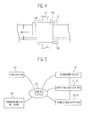
- FIG. 3 is a schematic view illustrating positions at which a meandering sensor and a wrinkle sensing portion are provided, respectively.
- FIG. 4 is a schematic view illustrating a state that meandering of a base material is generated.
- FIG. 5 is a block diagram of an apparatus of correcting belt-meandering according to an embodiment.
- a belt-meandering of a jelly roll of a secondary battery is controlled in a manner that a base material is correctly transferred by applying a constant pressure to the base material using a transverse moving motor based on a correction value read by a sensor for sensing a meandering.
- a meandering control method when the transfer speed of a base material is slow, the stress applied to the base material is low, and therefore, it is unlikely that a wrinkle or the like is generated on the base material.
- a constant pressure is applied to the base material in a direction substantially vertical to the transfer speed of the base material, and therefore, wrinkles are frequently generated.
- tension is rapidly increased by upper/lower rollers as applied to the base material, which likely adversely affects a subsequent process.
- Electrode assemblies used in secondary batteries may be classified into, for example, a winding-type electrode assembly and a stacking-type electrode assembly.
- the winding-type electrode assembly is formed by winding long sheet-shaped positive and negative electrode plates insulated by a separator.
- the positive electrode plate, the negative electrode plate and the separator, which are wound as described above, are called as an electrode plate.
- the electrode plate includes a positive electrode collector coated with a positive electrode active material, a negative electrode collector coated with a negative electrode active material, and an insulation film for insulating the two collectors from each other.
- the electrode plate is referred to as a base material for the convenience of description.
- the apparatus 100 of correcting belt-meandering includes a driver portion 110 , upper and lower rollers 120 and 130 , a support portion (or a support structure) 150 and a transverse moving mechanism 200 .
- the base material is an electrode plate for a secondary battery.
- the base material may be used for a device other than a secondary battery and include a sheet or a plate being transferred by rollers.
- the driver portion 110 drives the apparatus 100 by converting electric energy into rotational kinetic energy.
- the driver portion 110 provides a driving force to a gear portion 115 through a rotation shaft.
- the gear portion 115 provides a rotation force to a first rotation shaft 121 to which the upper roller 120 is fixed and a second rotation shaft 131 to which the lower roller 130 is fixed, which will be described later, using gears and various types of belt pulleys.
- the driver portion 110 rotates the first and second rotation shafts 121 and 131 reversely with respect to each other using a spur gear or the like.
- the gear portion 115 may be configured using various gears, belt pulleys, timing belts and the like, but they are all referred to as a gear portion for convenience of description.
- the upper and lower rollers 120 and 130 align and transfer a base material 10 that enters between the two rollers while being rotated in reverse directions to each other.
- the upper roller 120 is connected to the first rotation shaft 121 rotated by the driver portion 110
- the lower roller 130 is connected to the second rotation shaft 131 rotated by the driver portion 110 .
- the frictional force of the upper and lower rollers 120 and 130 may be increased so that the base material 10 is effectively transferred.
- the surfaces of the upper and lower rollers 120 and 130 may be properly treated so as to increase the frictional force.
- the frictional force generated between the upper roller 120 and/or lower roller 130 and base material 10 may be increased by coating a material with a high frictional coefficient on the outer circumferential surfaces of the upper and lower rollers 120 and 130 .
- the support portion 150 constitutes a body of the apparatus 100 .
- the support portion 150 supports the driver portion 110 , the gear portion including a driving shaft, the first rotation shaft 121 to which the upper roller 120 is fixed, and the second rotation shaft 131 to which the lower roller 130 is fixed.
- the transverse moving mechanism 200 moves the support portion 150 in a direction substantially perpendicular to the transfer direction D 1 ( FIG. 1 ) of the base material 10 .
- the transverse moving mechanism 200 may be implemented by installing separate guide rails or by using an air or oil pressure cylinder.
- a ball-screw type moving mechanism for converting a rotation motion into a rectilinear motion may be used to perform a precise movement.
- a meandering sensor 135 senses a meandering while the base material 10 is transferred.
- the meandering sensor 135 may be provided at an entry side of the upper and lower rollers 120 and 130 .
- a meandering M in a direction substantially vertical to a transfer direction may occur during the transfer of the base material 10 due to a possible unequal coating of the positive/negative electrode materials, vibration in winding process or the quality of equipment.
- the meandering sensor 135 senses the meandering M and provides the meandering M as an electrical signal to a control portion (or a controller) 300 ( FIG. 5 ) which will be described later.
- a pressure control cylinder 140 controls the pressure applied to the base material 10 by the upper and lower rollers 120 and 130 .
- the pressure control cylinder 140 controls the high and low of the first rotation shaft 121 to which the upper roller 120 is fixed by using an air or oil pressure cylinder.
- the air or oil pressure cylinder is used to simplify the configuration of the apparatus 100 , it is not limited thereto. That is, the air or oil pressure cylinder may be replaced by a high and low controlling mechanism using various methods.
- control portion 300 controls the transverse moving mechanism 200 based on a sensing signal, including the generation of a meandering, detected by the meandering sensor 135 .
- the control portion 300 continuously receives the sensing signal from the meandering sensor 135 , while the base material 10 is transferred.
- the sensing signal may include information about generation of the meandering, the generation direction of the meandering and the generation degree of the meandering.
- the control portion 300 may control, based on the sensing signal, the transverse moving mechanism 200 to be moved in the direction in which the meandering provided from the meandering sensor 135 is corrected. For example, the control portion 300 controls the transverse moving mechanism 200 to move the support portion 150 by the generation degree of the meandering in the opposite direction to the generation direction of the meandering.
- This embodiment relates to a case where the meandering sensor 135 does not provide the generation degree of a meandering to the control portion 300 . That is, the meandering sensor 135 provides only information about generation of the meandering and the generation direction of the meandering to the control portion 300 . In this case, if the control portion 300 controls the transverse moving mechanism 200 to be moved in the direction R in which the meandering is corrected, the entire support portion 150 including the upper and lower rollers 120 and 130 are moved in the corrected direction R ( FIG. 4 ).
- the meandering sensor 130 no longer provides information about the presence of the meandering to the control portion 300 . Then, the control portion 300 stops the position control of the transverse moving mechanism 200 .
- Each of wrinkle sensing portions (or at least one wrinkle sensor) 136 and 137 senses a wrinkle generated on the transferred base material 10 .
- each of the wrinkle sensing portions 136 and 137 includes a pulse laser transmitter (e.g., 136 ) that irradiates with a laser and has a receiving sensor (e.g., 137 ) that receives the laser irradiated from the pulse laser transmitter 136 .
- a plurality of transmitters 136 are provided according to the height of the base material 10
- a plurality of receiving sensors 137 are provided as many as the number of the transmitters 136 .
- the laser beam normally reaches the plurality of receiving sensors 137 .
- the laser does not reach the plurality of receiving sensors 137 .
- each of the wrinkle sensing portions 136 and 137 may be provided at the entry side of the upper and lower rollers 120 and 130 , at which wrinkles are frequently generated during the transfer of the base material 10 .
- the control portion 300 controls the pressure control cylinder 140 for a certain period of time so that the pressure applied to the base material 10 by the upper and lower rollers 120 and 130 is decreased. In a case where the upper and lower rollers 120 and 130 transfer the base material 10 at a weak pressure while being continuously rotated, the wrinkle generated on the base material 10 is smoothed out.
- meandering can be more precisely corrected.
- rollers for controlling meandering are driven at a line speed identical to the transfer speed of a base material, so that stress applied to the base material can be reduced in a transverse movement for controlling the meandering, thereby enhancing the quality of a secondary battery so manufactured.
Applications Claiming Priority (2)
| Application Number | Priority Date | Filing Date | Title |
|---|---|---|---|
| KR1020100080293A KR101113424B1 (ko) | 2010-08-19 | 2010-08-19 | 이차전지 권취기용 사행보정장치 |
| KR10-2010-0080293 | 2010-08-19 |
Publications (2)
| Publication Number | Publication Date |
|---|---|
| US20120043408A1 US20120043408A1 (en) | 2012-02-23 |
| US8893942B2 true US8893942B2 (en) | 2014-11-25 |
Family
ID=45593286
Family Applications (1)
| Application Number | Title | Priority Date | Filing Date |
|---|---|---|---|
| US13/181,415 Active 2033-07-03 US8893942B2 (en) | 2010-08-19 | 2011-07-12 | Apparatus for correcting belt-meandering for secondary battery |
Country Status (3)
| Country | Link |
|---|---|
| US (1) | US8893942B2 (ko) |
| KR (1) | KR101113424B1 (ko) |
| CN (1) | CN102437362B (ko) |
Families Citing this family (22)
| Publication number | Priority date | Publication date | Assignee | Title |
|---|---|---|---|---|
| KR101965707B1 (ko) * | 2012-11-01 | 2019-04-05 | 삼성에스디아이 주식회사 | 이차 전지의 전극 조립체용 권취기 |
| US9300003B2 (en) | 2013-08-05 | 2016-03-29 | Lg Chem, Ltd. | Meandering correction apparatus for electrode assembly |
| KR101587322B1 (ko) * | 2013-08-05 | 2016-01-20 | 주식회사 엘지화학 | 전극조립체용 사행보정장치 |
| KR101888211B1 (ko) * | 2013-12-09 | 2018-08-13 | 주식회사 엘지화학 | 스텝드 배터리 사행 방지 장치 및 방법 |
| KR101633168B1 (ko) * | 2014-01-06 | 2016-06-23 | 주식회사 엘지화학 | 스텝드 배터리의 정렬 장치 및 정렬 방법 |
| CN104525774B (zh) * | 2014-12-08 | 2016-10-12 | 深圳市吉阳自动化科技有限公司 | 一种极片输送及纠偏装置 |
| CN104668383A (zh) * | 2015-02-25 | 2015-06-03 | 昆山宝锦激光拼焊有限公司 | 一种送料辊导向中心纠偏装置 |
| CN105921635A (zh) * | 2016-04-28 | 2016-09-07 | 藤县顺舟造船有限公司 | 一种卷板机 |
| CN105834318A (zh) * | 2016-04-28 | 2016-08-10 | 藤县顺舟造船有限公司 | 一种卷板机的物料输送机构 |
| CN105947758A (zh) * | 2016-07-01 | 2016-09-21 | 无锡先导智能装备股份有限公司 | 一种自动纠偏装置 |
| KR200493852Y1 (ko) * | 2017-04-03 | 2021-06-16 | 주식회사 엘지에너지솔루션 | 공급 컨베이어를 포함하는 전극 접합 장치 |
| KR101888052B1 (ko) * | 2017-09-26 | 2018-08-13 | 장명희 | 이차전지 제조용 라미네이션 장치 |
| CN108217250A (zh) * | 2017-12-29 | 2018-06-29 | 徐雪华 | 金属基卷材开料防跑偏自动调整控制系统 |
| CN109693962A (zh) * | 2019-01-04 | 2019-04-30 | 无锡先导智能装备股份有限公司 | 一种校正机构及供料装置 |
| KR20220159640A (ko) | 2021-05-26 | 2022-12-05 | 주식회사 엘지에너지솔루션 | 전극의 사행 보정장치 및 전극의 사행 보정방법 |
| CN115812258A (zh) | 2021-02-26 | 2023-03-17 | 株式会社Lg新能源 | 用于电极的蛇行校正装置和用于电极的蛇行校正方法 |
| KR20220122097A (ko) | 2021-02-26 | 2022-09-02 | 주식회사 엘지에너지솔루션 | 전극의 사행 보정장치 및 전극의 사행 보정방법 |
| KR20220159641A (ko) | 2021-05-26 | 2022-12-05 | 주식회사 엘지에너지솔루션 | 전극의 사행 보정장치 및 전극의 사행 보정방법 |
| EP4152458A1 (en) | 2021-02-26 | 2023-03-22 | LG Energy Solution, Ltd. | Meandering correction device for electrode and meandering correction method for electrode |
| CN113104634B (zh) * | 2021-04-13 | 2023-04-14 | 内蒙古联晟新能源材料有限公司 | 一种用于铸坯板料自动上料的控制系统 |
| CN113389039B (zh) * | 2021-04-23 | 2023-05-12 | 安徽甬安雨具有限公司 | 一种雨衣生产用布料传输裁断集成设备 |
| CN116081370B (zh) * | 2023-03-22 | 2023-09-08 | 宁德时代新能源科技股份有限公司 | 极片送料装置、卷绕设备以及极片纠偏方法 |
Citations (12)
| Publication number | Priority date | Publication date | Assignee | Title |
|---|---|---|---|---|
| JPH09221252A (ja) | 1996-02-16 | 1997-08-26 | Sony Corp | 帯状部材の走行案内装置と帯状部材の走行案内方法 |
| JPH10175752A (ja) | 1996-12-18 | 1998-06-30 | Canon Inc | シート搬送装置並びにこれを備えた画像読取装置及び画像形成装置 |
| US6059285A (en) | 1996-12-18 | 2000-05-09 | Canon Kabushiki Kaisha | Sheet conveying apparatus |
| JP2002093408A (ja) | 2000-09-14 | 2002-03-29 | Toshiba Battery Co Ltd | 電池用電極シートの加工方法、加工装置 |
| JP2005079079A (ja) | 2003-08-28 | 2005-03-24 | Kaido Seisakusho:Kk | 電池素子捲回装置用蛇行補正装置 |
| JP2005116492A (ja) | 2003-10-06 | 2005-04-28 | Kaido Seisakusho:Kk | 電池素子捲回装置用(ローラー外径可変型)蛇行補正装置 |
| JP2007161474A (ja) | 2005-12-09 | 2007-06-28 | Kaido Seisakusho:Kk | 薄帯捲回装置用(ローラー位置可変型)蛇行補正装置 |
| JP2008063150A (ja) | 2007-12-14 | 2008-03-21 | Hirano Tecseed Co Ltd | ウエブの蛇行修正装置 |
| WO2009019781A1 (ja) | 2007-08-09 | 2009-02-12 | Kaido Manufacturing Co., Ltd. | 巻回装置用変位補正装置 |
| JP2009132524A (ja) | 2007-11-30 | 2009-06-18 | Toyota Motor Corp | 搬送膜のしわ検知装置およびその方法 |
| WO2009125298A2 (en) * | 2008-04-10 | 2009-10-15 | Toyota Jidosha Kabushiki Kaisha | Web conveying apparatus and web conveying control method |
| WO2010010705A1 (ja) | 2008-07-25 | 2010-01-28 | 株式会社Ihi | 固体高分子型燃料電池用セパレータ製造方法及び設備 |
-
2010
- 2010-08-19 KR KR1020100080293A patent/KR101113424B1/ko active IP Right Grant
-
2011
- 2011-07-12 US US13/181,415 patent/US8893942B2/en active Active
- 2011-08-10 CN CN201110234338.XA patent/CN102437362B/zh active Active
Patent Citations (13)
| Publication number | Priority date | Publication date | Assignee | Title |
|---|---|---|---|---|
| JPH09221252A (ja) | 1996-02-16 | 1997-08-26 | Sony Corp | 帯状部材の走行案内装置と帯状部材の走行案内方法 |
| JPH10175752A (ja) | 1996-12-18 | 1998-06-30 | Canon Inc | シート搬送装置並びにこれを備えた画像読取装置及び画像形成装置 |
| US6059285A (en) | 1996-12-18 | 2000-05-09 | Canon Kabushiki Kaisha | Sheet conveying apparatus |
| JP2002093408A (ja) | 2000-09-14 | 2002-03-29 | Toshiba Battery Co Ltd | 電池用電極シートの加工方法、加工装置 |
| JP2005079079A (ja) | 2003-08-28 | 2005-03-24 | Kaido Seisakusho:Kk | 電池素子捲回装置用蛇行補正装置 |
| JP2005116492A (ja) | 2003-10-06 | 2005-04-28 | Kaido Seisakusho:Kk | 電池素子捲回装置用(ローラー外径可変型)蛇行補正装置 |
| JP2007161474A (ja) | 2005-12-09 | 2007-06-28 | Kaido Seisakusho:Kk | 薄帯捲回装置用(ローラー位置可変型)蛇行補正装置 |
| WO2009019781A1 (ja) | 2007-08-09 | 2009-02-12 | Kaido Manufacturing Co., Ltd. | 巻回装置用変位補正装置 |
| JP2009132524A (ja) | 2007-11-30 | 2009-06-18 | Toyota Motor Corp | 搬送膜のしわ検知装置およびその方法 |
| JP2008063150A (ja) | 2007-12-14 | 2008-03-21 | Hirano Tecseed Co Ltd | ウエブの蛇行修正装置 |
| WO2009125298A2 (en) * | 2008-04-10 | 2009-10-15 | Toyota Jidosha Kabushiki Kaisha | Web conveying apparatus and web conveying control method |
| WO2010010705A1 (ja) | 2008-07-25 | 2010-01-28 | 株式会社Ihi | 固体高分子型燃料電池用セパレータ製造方法及び設備 |
| US20110111329A1 (en) | 2008-07-25 | 2011-05-12 | Ihi Corporation | Method and facility for producing separator for use in polymer electrolyte fuel cell |
Non-Patent Citations (2)
| Title |
|---|
| Chinese Office Action dated Dec. 16, 2013 for Chinese Patent Application No. CN 201110234338.X which shares priority of Korean Patent Application No. KR 10-2010-0080293 with captioned U.S. Appl. No. 13/181,415, and cites the above-identified references numbered 1-3. |
| Machine Translation of WO 2009/019781 A1, Feb. 12, 2009. * |
Also Published As
| Publication number | Publication date |
|---|---|
| KR20120017597A (ko) | 2012-02-29 |
| US20120043408A1 (en) | 2012-02-23 |
| CN102437362A (zh) | 2012-05-02 |
| CN102437362B (zh) | 2014-09-03 |
| KR101113424B1 (ko) | 2012-03-02 |
Similar Documents
| Publication | Publication Date | Title |
|---|---|---|
| US8893942B2 (en) | Apparatus for correcting belt-meandering for secondary battery | |
| US9415942B2 (en) | Conveyor and conveying method | |
| EP2816653B1 (en) | Conveyance device and conveyance method | |
| JP2012129147A (ja) | 電極材料のロールプレス設備 | |
| US9139373B2 (en) | Conveyor and conveying method | |
| EP2816652B1 (en) | Battery pressing apparatus and battery pressing method | |
| CA2731558C (en) | Method and facility for producing separator for use in polymer electrolyte fuel cell | |
| CN115064755B (zh) | 卷绕方法及卷绕系统 | |
| CN109301147B (zh) | 极耳错位控制方法及卷绕装置 | |
| WO2012099073A1 (ja) | ガラスロール、ガラスロール製造装置、およびガラスロール製造方法 | |
| KR101264517B1 (ko) | 라미네이팅 장치 | |
| CN105921365B (zh) | 一种高精度涂布机 | |
| EP0796732A2 (en) | Method for manufacturing laminates and apparatus performing the method | |
| JP2009160910A (ja) | ラミネート物の厚みの検知機能を具えたラミネーター | |
| KR20230153767A (ko) | 이차전지 셀 제조용 전극 절단장치 및 그 제어 방법 | |
| US10399314B2 (en) | Lamination device | |
| KR20230090144A (ko) | 전극조립체의 외경측정장치와 외경측정방법 | |
| KR102218546B1 (ko) | 그라비어 코팅 장치 | |
| EP4318775A1 (en) | Separator thickness adjusting device and method, and wound electrode assembly production system | |
| CN218809395U (zh) | 铜带收卷机构 | |
| CN215946274U (zh) | 薄膜加工设备及薄膜偏移修正装置 | |
| CN219368597U (zh) | 厚度测量装置 | |
| TW202311145A (zh) | 薄膜加工設備、薄膜偏移修正裝置及薄膜偏移修正方法 | |
| CN114211768B (zh) | 一种复合膜制备用ptfe膜辅助复合装置 | |
| CN218578115U (zh) | 一种弧面滚压贴膜装置 |
Legal Events
| Date | Code | Title | Description |
|---|---|---|---|
| AS | Assignment |
Owner name: SAMSUNG SDI CO., LTD, KOREA, REPUBLIC OF Free format text: ASSIGNMENT OF ASSIGNORS INTEREST;ASSIGNORS:OH, DAE-SIK;BAE, KEON-SOO;CHO, GI-BONG;AND OTHERS;REEL/FRAME:026588/0542 Effective date: 20110707 |
|
| FEPP | Fee payment procedure |
Free format text: PAYOR NUMBER ASSIGNED (ORIGINAL EVENT CODE: ASPN); ENTITY STATUS OF PATENT OWNER: LARGE ENTITY |
|
| STCF | Information on status: patent grant |
Free format text: PATENTED CASE |
|
| MAFP | Maintenance fee payment |
Free format text: PAYMENT OF MAINTENANCE FEE, 4TH YEAR, LARGE ENTITY (ORIGINAL EVENT CODE: M1551) Year of fee payment: 4 |
|
| MAFP | Maintenance fee payment |
Free format text: PAYMENT OF MAINTENANCE FEE, 8TH YEAR, LARGE ENTITY (ORIGINAL EVENT CODE: M1552); ENTITY STATUS OF PATENT OWNER: LARGE ENTITY Year of fee payment: 8 |