US8893719B2 - Intra-oral continuous positive airway pressure (CPAP) interfaces - Google Patents
Intra-oral continuous positive airway pressure (CPAP) interfaces Download PDFInfo
- Publication number
- US8893719B2 US8893719B2 US13/203,982 US201013203982A US8893719B2 US 8893719 B2 US8893719 B2 US 8893719B2 US 201013203982 A US201013203982 A US 201013203982A US 8893719 B2 US8893719 B2 US 8893719B2
- Authority
- US
- United States
- Prior art keywords
- intra
- oral
- interface
- patient
- cpap
- Prior art date
- Legal status (The legal status is an assumption and is not a legal conclusion. Google has not performed a legal analysis and makes no representation as to the accuracy of the status listed.)
- Expired - Fee Related, expires
Links
- 238000000034 method Methods 0.000 claims abstract description 20
- 201000002859 sleep apnea Diseases 0.000 claims abstract description 10
- 238000012545 processing Methods 0.000 claims description 17
- 239000000463 material Substances 0.000 claims description 10
- 238000004891 communication Methods 0.000 claims description 7
- 230000008569 process Effects 0.000 claims description 7
- 238000007789 sealing Methods 0.000 claims description 7
- 206010021079 Hypopnoea Diseases 0.000 claims description 6
- 206010041235 Snoring Diseases 0.000 claims description 6
- 210000002200 mouth mucosa Anatomy 0.000 claims description 6
- 230000002146 bilateral effect Effects 0.000 claims description 5
- 229940037201 oris Drugs 0.000 claims description 5
- 230000000875 corresponding effect Effects 0.000 claims description 4
- 210000001519 tissue Anatomy 0.000 claims description 4
- 230000002596 correlated effect Effects 0.000 claims description 2
- 210000004877 mucosa Anatomy 0.000 claims description 2
- 239000012530 fluid Substances 0.000 claims 2
- 210000000214 mouth Anatomy 0.000 description 39
- 239000007789 gas Substances 0.000 description 8
- 230000009471 action Effects 0.000 description 7
- 230000033001 locomotion Effects 0.000 description 7
- 230000002829 reductive effect Effects 0.000 description 7
- 230000000241 respiratory effect Effects 0.000 description 7
- 230000001225 therapeutic effect Effects 0.000 description 7
- QVGXLLKOCUKJST-UHFFFAOYSA-N atomic oxygen Chemical compound [O] QVGXLLKOCUKJST-UHFFFAOYSA-N 0.000 description 6
- 210000003205 muscle Anatomy 0.000 description 6
- 229910052760 oxygen Inorganic materials 0.000 description 6
- 239000001301 oxygen Substances 0.000 description 6
- 230000029058 respiratory gaseous exchange Effects 0.000 description 6
- CURLTUGMZLYLDI-UHFFFAOYSA-N Carbon dioxide Chemical compound O=C=O CURLTUGMZLYLDI-UHFFFAOYSA-N 0.000 description 5
- 229920000249 biocompatible polymer Polymers 0.000 description 4
- 230000000694 effects Effects 0.000 description 4
- 208000014674 injury Diseases 0.000 description 4
- 230000001720 vestibular Effects 0.000 description 4
- XUIMIQQOPSSXEZ-UHFFFAOYSA-N Silicon Chemical compound [Si] XUIMIQQOPSSXEZ-UHFFFAOYSA-N 0.000 description 3
- 208000027418 Wounds and injury Diseases 0.000 description 3
- 208000008784 apnea Diseases 0.000 description 3
- 229910002092 carbon dioxide Inorganic materials 0.000 description 3
- 230000006378 damage Effects 0.000 description 3
- 238000000465 moulding Methods 0.000 description 3
- 230000002265 prevention Effects 0.000 description 3
- 230000009467 reduction Effects 0.000 description 3
- 206010003497 Asphyxia Diseases 0.000 description 2
- 210000003484 anatomy Anatomy 0.000 description 2
- 230000004888 barrier function Effects 0.000 description 2
- 239000000560 biocompatible material Substances 0.000 description 2
- 230000036772 blood pressure Effects 0.000 description 2
- 239000001569 carbon dioxide Substances 0.000 description 2
- 230000008859 change Effects 0.000 description 2
- 238000011513 continuous positive airway pressure therapy Methods 0.000 description 2
- 230000006870 function Effects 0.000 description 2
- 210000003128 head Anatomy 0.000 description 2
- 210000001847 jaw Anatomy 0.000 description 2
- 238000004519 manufacturing process Methods 0.000 description 2
- 238000005259 measurement Methods 0.000 description 2
- 208000010125 myocardial infarction Diseases 0.000 description 2
- 238000006213 oxygenation reaction Methods 0.000 description 2
- 230000002093 peripheral effect Effects 0.000 description 2
- 230000005855 radiation Effects 0.000 description 2
- 229910052710 silicon Inorganic materials 0.000 description 2
- 239000010703 silicon Substances 0.000 description 2
- 210000001584 soft palate Anatomy 0.000 description 2
- 238000002560 therapeutic procedure Methods 0.000 description 2
- 208000006545 Chronic Obstructive Pulmonary Disease Diseases 0.000 description 1
- 206010010904 Convulsion Diseases 0.000 description 1
- 206010012373 Depressed level of consciousness Diseases 0.000 description 1
- 206010013647 Drowning Diseases 0.000 description 1
- 208000030984 MIRAGE syndrome Diseases 0.000 description 1
- 208000006011 Stroke Diseases 0.000 description 1
- 208000003443 Unconsciousness Diseases 0.000 description 1
- 238000009825 accumulation Methods 0.000 description 1
- 230000008901 benefit Effects 0.000 description 1
- 230000015572 biosynthetic process Effects 0.000 description 1
- 210000004556 brain Anatomy 0.000 description 1
- 230000006931 brain damage Effects 0.000 description 1
- 231100000874 brain damage Toxicity 0.000 description 1
- 208000029028 brain injury Diseases 0.000 description 1
- 206010006514 bruxism Diseases 0.000 description 1
- 230000000747 cardiac effect Effects 0.000 description 1
- 229940066823 comfort gel Drugs 0.000 description 1
- 230000003247 decreasing effect Effects 0.000 description 1
- 238000013461 design Methods 0.000 description 1
- 229940124645 emergency medicine Drugs 0.000 description 1
- 206010015037 epilepsy Diseases 0.000 description 1
- 208000028329 epileptic seizure Diseases 0.000 description 1
- 238000002474 experimental method Methods 0.000 description 1
- 238000001125 extrusion Methods 0.000 description 1
- 239000004744 fabric Substances 0.000 description 1
- 230000001815 facial effect Effects 0.000 description 1
- 239000010408 film Substances 0.000 description 1
- 210000001061 forehead Anatomy 0.000 description 1
- 210000004195 gingiva Anatomy 0.000 description 1
- 230000036541 health Effects 0.000 description 1
- 238000009532 heart rate measurement Methods 0.000 description 1
- 238000003780 insertion Methods 0.000 description 1
- 230000037431 insertion Effects 0.000 description 1
- 230000002427 irreversible effect Effects 0.000 description 1
- 230000000670 limiting effect Effects 0.000 description 1
- 238000012423 maintenance Methods 0.000 description 1
- 230000014759 maintenance of location Effects 0.000 description 1
- 238000012986 modification Methods 0.000 description 1
- 230000004048 modification Effects 0.000 description 1
- 239000002991 molded plastic Substances 0.000 description 1
- 238000012544 monitoring process Methods 0.000 description 1
- 210000002445 nipple Anatomy 0.000 description 1
- 230000037361 pathway Effects 0.000 description 1
- 210000005259 peripheral blood Anatomy 0.000 description 1
- 239000011886 peripheral blood Substances 0.000 description 1
- 230000035479 physiological effects, processes and functions Effects 0.000 description 1
- 239000004033 plastic Substances 0.000 description 1
- 229920000642 polymer Polymers 0.000 description 1
- 229920001296 polysiloxane Polymers 0.000 description 1
- 238000003825 pressing Methods 0.000 description 1
- TVLSRXXIMLFWEO-UHFFFAOYSA-N prochloraz Chemical compound C1=CN=CN1C(=O)N(CCC)CCOC1=C(Cl)C=C(Cl)C=C1Cl TVLSRXXIMLFWEO-UHFFFAOYSA-N 0.000 description 1
- 230000011514 reflex Effects 0.000 description 1
- 230000000717 retained effect Effects 0.000 description 1
- 238000005096 rolling process Methods 0.000 description 1
- 210000003296 saliva Anatomy 0.000 description 1
- 238000000926 separation method Methods 0.000 description 1
- 238000004904 shortening Methods 0.000 description 1
- 239000010409 thin film Substances 0.000 description 1
- 238000012546 transfer Methods 0.000 description 1
- 230000008733 trauma Effects 0.000 description 1
- 238000009423 ventilation Methods 0.000 description 1
- 239000003190 viscoelastic substance Substances 0.000 description 1
Images


Classifications
-
- A—HUMAN NECESSITIES
- A61—MEDICAL OR VETERINARY SCIENCE; HYGIENE
- A61M—DEVICES FOR INTRODUCING MEDIA INTO, OR ONTO, THE BODY; DEVICES FOR TRANSDUCING BODY MEDIA OR FOR TAKING MEDIA FROM THE BODY; DEVICES FOR PRODUCING OR ENDING SLEEP OR STUPOR
- A61M16/00—Devices for influencing the respiratory system of patients by gas treatment, e.g. ventilators; Tracheal tubes
- A61M16/08—Bellows; Connecting tubes ; Water traps; Patient circuits
- A61M16/0816—Joints or connectors
-
- A—HUMAN NECESSITIES
- A61—MEDICAL OR VETERINARY SCIENCE; HYGIENE
- A61M—DEVICES FOR INTRODUCING MEDIA INTO, OR ONTO, THE BODY; DEVICES FOR TRANSDUCING BODY MEDIA OR FOR TAKING MEDIA FROM THE BODY; DEVICES FOR PRODUCING OR ENDING SLEEP OR STUPOR
- A61M16/00—Devices for influencing the respiratory system of patients by gas treatment, e.g. ventilators; Tracheal tubes
- A61M16/04—Tracheal tubes
- A61M16/0434—Cuffs
- A61M16/044—External cuff pressure control or supply, e.g. synchronisation with respiration
-
- A—HUMAN NECESSITIES
- A61—MEDICAL OR VETERINARY SCIENCE; HYGIENE
- A61M—DEVICES FOR INTRODUCING MEDIA INTO, OR ONTO, THE BODY; DEVICES FOR TRANSDUCING BODY MEDIA OR FOR TAKING MEDIA FROM THE BODY; DEVICES FOR PRODUCING OR ENDING SLEEP OR STUPOR
- A61M16/00—Devices for influencing the respiratory system of patients by gas treatment, e.g. ventilators; Tracheal tubes
- A61M16/04—Tracheal tubes
- A61M16/0488—Mouthpieces; Means for guiding, securing or introducing the tubes
- A61M16/049—Mouthpieces
- A61M16/0493—Mouthpieces with means for protecting the tube from damage caused by the patient's teeth, e.g. bite block
-
- A—HUMAN NECESSITIES
- A61—MEDICAL OR VETERINARY SCIENCE; HYGIENE
- A61M—DEVICES FOR INTRODUCING MEDIA INTO, OR ONTO, THE BODY; DEVICES FOR TRANSDUCING BODY MEDIA OR FOR TAKING MEDIA FROM THE BODY; DEVICES FOR PRODUCING OR ENDING SLEEP OR STUPOR
- A61M16/00—Devices for influencing the respiratory system of patients by gas treatment, e.g. ventilators; Tracheal tubes
- A61M16/06—Respiratory or anaesthetic masks
- A61M16/0666—Nasal cannulas or tubing
-
- G—PHYSICS
- G10—MUSICAL INSTRUMENTS; ACOUSTICS
- G10D—STRINGED MUSICAL INSTRUMENTS; WIND MUSICAL INSTRUMENTS; ACCORDIONS OR CONCERTINAS; PERCUSSION MUSICAL INSTRUMENTS; AEOLIAN HARPS; SINGING-FLAME MUSICAL INSTRUMENTS; MUSICAL INSTRUMENTS NOT OTHERWISE PROVIDED FOR
- G10D9/00—Details of, or accessories for, wind musical instruments
- G10D9/02—Mouthpieces; Reeds; Ligatures
-
- A—HUMAN NECESSITIES
- A61—MEDICAL OR VETERINARY SCIENCE; HYGIENE
- A61M—DEVICES FOR INTRODUCING MEDIA INTO, OR ONTO, THE BODY; DEVICES FOR TRANSDUCING BODY MEDIA OR FOR TAKING MEDIA FROM THE BODY; DEVICES FOR PRODUCING OR ENDING SLEEP OR STUPOR
- A61M16/00—Devices for influencing the respiratory system of patients by gas treatment, e.g. ventilators; Tracheal tubes
- A61M16/06—Respiratory or anaesthetic masks
- A61M16/0683—Holding devices therefor
-
- A—HUMAN NECESSITIES
- A61—MEDICAL OR VETERINARY SCIENCE; HYGIENE
- A61M—DEVICES FOR INTRODUCING MEDIA INTO, OR ONTO, THE BODY; DEVICES FOR TRANSDUCING BODY MEDIA OR FOR TAKING MEDIA FROM THE BODY; DEVICES FOR PRODUCING OR ENDING SLEEP OR STUPOR
- A61M2205/00—General characteristics of the apparatus
- A61M2205/02—General characteristics of the apparatus characterised by a particular materials
- A61M2205/0216—Materials providing elastic properties, e.g. for facilitating deformation and avoid breaking
-
- A—HUMAN NECESSITIES
- A61—MEDICAL OR VETERINARY SCIENCE; HYGIENE
- A61M—DEVICES FOR INTRODUCING MEDIA INTO, OR ONTO, THE BODY; DEVICES FOR TRANSDUCING BODY MEDIA OR FOR TAKING MEDIA FROM THE BODY; DEVICES FOR PRODUCING OR ENDING SLEEP OR STUPOR
- A61M2210/00—Anatomical parts of the body
- A61M2210/06—Head
- A61M2210/0625—Mouth
Definitions
- the present invention relates generally to apparatus and methods for providing gases intra-orally, and more specifically to ergonomic apparatus and methods for providing continuous positive air pressure to a mammalian subject.
- Mammalian subjects require a semi-continuous supply of air, such that the oxygen level in the brain is retained above a threshold level. There are many conditions and situations under which the air supply is temporarily stopped or reduced. These may include, but are not limited to, sleep apnea, heart attack, epileptic seizure and drowning. If the subject does not receive oxygen within a number of seconds/minutes, the result can lead to irreversible brain damage, and, in some cases, death.
- U.S. Pat. No. 4,305,387 which describes a mouth closure for providing artificial respiration to patients, which consists of a deformable elliptical plate, whose periphery is surrounded by a tube.
- the tube is formed in the shape of an air hose made of an elastic film with a hose for admission of air.
- a tube passes through the plate in a central region.
- the mouth closure is placed in the dentilabial cavity of the patient's upper and lower jaws.
- the tube in association with the gums and the lips and cheeks, seals the oral cavity from the outside.
- a flow of air through the tube therefore enters the respiratory passages of the patient and also passes back from the respiratory passages, through the tube, to the outside.
- This publication teaches the requirement for a medical professional to fill the airholes, thereby preventing a user from using it just by itself. This device is not self-adaptable.
- US Patent Publication No. US2002005201 describes an improved nasal mask, for delivering CPAP therapy to patients.
- the nasal mask has a sliding engagement to the headgear.
- the sliding engagement allows substantial relative lateral movement eg: when face is distorted from sleeping on side, while still providing adequate compressive force to avoid side leakage.
- the sliding engagement also allows easy release from the headgear.
- US Patent Publication No. US2003075182 discloses an application device for a breathing mask arrangement, including a base portion, a holding portion structured to support a mask and pivotally mounted to the base portion for pivotal movement about a first pivot axis, a right arm element pivotally mounted to the base portion for pivotal movement about a second pivot axis, and a left arm element pivotally mounted to the base portion for pivotal movement about a third pivot axis.
- the right and left arm elements are each provided with a contact portion for bearing against a right and a left forehead zone respectively of a mask user.
- the holding portion, the right arm element, and left arm element can be pivoted with respect to the base portion about the respective first, second, and third pivot axes.
- US Patent Publication No. US2003183227 describes a CPAP device and a method for treating sleep apnea, using a head appliance with an oral adaptor comprising a tube partially inserted in a person's mouth and a diaphragm applied over the tube against the mouth, such that the lips are formed into a tight seal with the tube.
- a nasal seal is described comprising two rollers to which a strap is attached, so that the nasal seal is easily put in place, adjusted and maintained by rolling the rollers on the nose sides or pulling the straps.
- US Patent Publication No. US2003089371A describes a mouthpiece for oral delivery of CPAP treatment, which has a vestibular shield for location between the teeth and lips/cheeks of a wearer.
- the vestibular shield is dimensioned to extend laterally into the buccal vestibule and vertically to overlap the gums.
- the vestibular shield is formed from a very supple material.
- a gases pathway is provided through the vestibular shield and may include a hard plastic insert through the shield, including a standard breathing conduit connection at its outer end.
- a short stub conduit on the outlet side of the shield passes between the wearers upper and lower teeth.
- a connection for connecting the mouthpiece to a breathing circuit is also provided which reduces the transfer of forces caused by movement therebetween.
- the connection may include a short length of highly flexible gases conduit, an elbow and a swivel connection.
- US Patent Publication No. US2005236003A describes a sleep apnea prevention device which is designed to move the lower jaw forward, keep teeth and lips apart, and guarantee full oxygenation needs with oral airway that is centered in an anterior dental-buccal space shield and wing portion.
- This, with mouth guard for lower teeth is all a unit as a single piece of molded plastic or any other material; with said unit modeled from four theoretical portions including a barrier-like anterior portion fitted and anchored between anterior teeth-gums and behind the lips in the anterior buccal space with flanking wing like fins extending in that space laterally back to the upper second molars, thus allowing good retention in place whether mouth is open wide or minimally, or closed or moving side to side.
- Said shield is functionally tethered at the top front which becomes its fulcrum as it engages the lower teeth with a mouth guard portion and swings the lower jaw forward with bite activity; mouth guard pylon like blocks mounted on the mouth guard superior surface keep the teeth apart and help swing the jaw forward.
- the barrier in midline supports a nipple like projection which is, actually, a tube-like conduit which keeps the lips apart and becomes an oral airway.
- This device can be used alone or with CPAP face mask in place and user must coordinate with health provider to insure sleep apnea is only moderate and not just masked and inadequately treated. It usually does help snoring and bruxism.
- World Patent Publication No. WO06079149A discloses an oral leak prevention device for patients who use nasal CPAP machines (Continuous positive airway pressure).
- the device minimizes air escaping through the mouth of patient while they are being pressurized through the nasal passage by the airflow of a CPAP machine.
- the oral leak prevention device is placed over the mouth and securing straps hold the device in place.
- the built in valve is to allow the patient to inhale if the CPAP machine should fail but under normal circumstances the valve stops air escaping from the mouth while the patient is sleeping.
- a respiratory mask arrangement that can be used in the framework of CPAP therapy for treating sleep-related disturbances, for example.
- a respiratory mask arrangement comprises a sealing lip device to be placed on the facial surface of a mask user, a covering device which defines a mask interior in cooperation with the sealing lip device, and a respiratory gas conduit unit for delivering respiratory gas to the mask interior that is defined by the covering device and is connected to the nostril and/or oral opening of the mask user.
- At least some sections of the covering device are embodied as an air-permeable structure.
- World Patent Publication No. WO08041237A describes an intra-oral continuous positive airway pressure (CPAP) device that comprises a tube connected to a source of positive air pressure, and a shield connected to, or integrally formed with, the tube and adapted to be inserted within buccal sulci in such a way that facilitates oral cavity sealing.
- the shield has a central part formed with an aperture in communication with the tube, and right and left longitudinally extending projections adjoining, and of substantial bilateral symmetry with respect to the central part.
- Each of the projections has adjoining upper and lower regions and each of the regions has adjoining proximal and distal portions, Each of the projections is dimensioned such that a distal portion has a thickness substantially equal to, or greater than, a buccal sulcus potential space gap, and is configured, when inserted within a buccal sulcus, in such a way so as to adhere to the oral mucosa, to occupy the entire volume of buccal sulcus potential space, and to seal the oral cavity.
- improved methods and apparatus are provided for preventing death and injury in patients suffering from sleep apnea, stroke, heart attack, trauma, COPD, Alzheimer and other conditions.
- a method and an intra-oral interface for providing continuous positive airway pressure (CPAP) to a patient in other preferred embodiments of the present invention, a method and an intra-oral interface for providing continuous positive airway pressure (CPAP) to a patient.
- CPAP continuous positive airway pressure
- an intraoral interface which is non-obtrusive, comfortable, does not impinge on or touch the soft palate, tongue or teeth.
- the interface is simple to use, lightweight and ergonomically designed.
- an ergonomically formed intra-oral interface for providing an unconscious, semi-conscious or sleeping patient with continuous positive airway pressure (CPAP).
- CPAP continuous positive airway pressure
- an interface provides for continuous positive airway pressure (CPAP) maintenance in a patient.
- CPAP continuous positive airway pressure
- an interface provides for non invasive ventilation in a patient.
- an intra-oral continuous positive airway pressure (CPAP) interface including;
- the intra-oral section is adapted to be inserted within buccal sulci occupying substantially the entire volume of a buccal sulcus potential space upon receiving air in such a way that facilitates oral cavity sealing, and to retain oral cavity sealing in a sealed state even without occupying the entire volume of a buccal sulcus potential space.
- the interface is lightweight. Preferably, the interface weighs less than 60 grams. Yet more preferably, the interface weighs 20 to 50 grams.
- the interface is non-obtrusive.
- the interface is constructed and configured to conform to mouth physiology of a patient.
- the interface is constructed and configured to be self-adaptable to a physical intra-oral structure of every individual user.
- Self-adaptable are active and passive interface features that allow it to automatically fit to different oral anatomy structures, sizes and functions.
- the interface is constructed and configured to passively form a seal by occupying a potential space between the lips and gums of a user.
- the interface is constructed and configured to actively seal a potential space between the lips and gums of a user.
- the circumferential hollow lip is adapted to be inflated by exhaled air of the user.
- the interface is made of a biocompatible polymer.
- the polymer of the circumferential hollow lip includes collapsible portions.
- the collapsible portions exhibit a pre-loaded force which is adapted to press gently onto the gums and lips of the user upon insertion to a mouth of the user, thereby forming a seal.
- the orifice intra-oral section is integrally formed with the tubular section.
- the intra-oral section is provided with a central part formed with an aperture in communication with the tube, and right and left longitudinally extending projections adjoining, and of substantial bilateral symmetry with respect to, the central part, each of the projections having adjoining upper and lower regions and each of the regions having adjoining proximal and distal portions,
- each of the projections is continuously adherable to the oral mucosa from the orbicularis oris muscle to the attached gingiva.
- the intra-oral section has a longitudinal length equal to 10 to 16 teeth. In some cases, the intra-oral section has a longitudinal length equal to approximately 12 teeth.
- a most distal location of a proximal portion and a transitional point between the orbicularis oris muscle and the buccinator muscle are approximately at a common height when the shield in inserted within the potential space of the buccal sulci.
- a distal portion may be considerably thicker than an adjoining proximal portion and than a corresponding distal portion of the buccal sulcus potential space to such a degree that upper and lower lip portions disposed buccally to the central part are urged to sealingly engage the tube.
- an intra-oral CPAP interface constructed and configured to supply sufficient air to the patient at an air pressure of 2-20 cm H 2 O. This is approximately 15-60% less air pressure than the requirements of interfaces known in the art for similar therapeutic results.
- the intra-oral (CPAP) interface is constructed and configured to supply sufficient air to the patient at an air pressure of 2-10 cm H 2 O.
- the interface is constructed and configured to supply sufficient air to the patient at an air pressure of 4-8 cm H 2 O.
- the interface is constructed and configured to supply sufficient air to the patient at an air pressure reduced by 10-60% relative to an existing CPAP interface.
- the interface is constructed and configured to supply sufficient air to the patient at an air pressure reduced by 15-50% relative to an existing CPAP interface.
- an intra-oral interface including;
- an intra-oral interface that is not connected to a CPAP machine during CPAP treatment.
- the CPAP treatment is supplied via other nasal or ora-nasal interfaces and in such a case the air pressure needed for a successful therapy is reduced by 10-60% relative to an existing CPAP interface, while the intra oral interface in this embodiment support and augment the action of the existing CPAP interface.
- a system for continuously providing a user with sufficient air including;
- the coils include fixed magnets pairs.
- the signals are adapted to induce at least one of attraction and repulsion in the magnet pairs thereby decreasing or increasing the air volume in the interface.
- the sensors are adapted to measure at least one parameter selected from the group consisting of air pressure, air flow speed, oxygen saturation, carbon dioxide concentration, pulse rate and blood pressure.
- the system is adapted to prevent at least one of sleep apnea, snoring and hypopnea.
- the senor is selected from an integral pulse oximeter and a CO-oximeter.
- the sensors transmit data and or processes data to the flow generator, which, in turn, uses the data and regulates the air is supplies and thus work in concert with the interface to provide a better therapeutic compliance to the patient's needs.
- a method for forming an intra-oral CPAP interface including;
- FIG. 1 is a simplified pictorial illustration of a perspective view of a CPAP (continuous positive air pressure) intra-oral self adaptable interface, in accordance with an embodiment of the present invention
- FIG. 2 is a simplified pictorial illustration of a rear view of the CPAP intra-oral interface of FIG. 1 in accordance with an embodiment of the present invention
- FIG. 3 is a simplified pictorial illustration of an upper view of a CPAP intra-oral interface of FIG. 1 , in accordance with an embodiment of the present invention
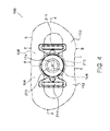
- FIG. 4 is a simplified pictorial illustration of a front view of a CPAP intra-oral interface of FIG. 1 , in accordance with an embodiment of the present invention
- FIG. 5 is a simplified flow chart of a method for forming a general purpose CPAP intra-oral interface, in accordance with an embodiment of the present invention
- FIG. 6A is a simplified pictorial illustration of a vertical cross section of the CPAP intra-oral interface of FIG. 1 with a CPAP flow generator during inhalation, in accordance with an embodiment of the present invention
- FIG. 6B is a simplified pictorial illustration of a vertical cross section of the CPAP intra-oral interface of FIG. 1 with air introduction from a CPAP flow generator, during exhalation, in accordance with an embodiment of the present invention
- FIG. 7A is a simplified pictorial illustration of a perspective view of a CPAP intra-oral interface of FIG. 1 with a retainer element, in accordance with an embodiment of the present invention
- FIG. 7B shows a number of views of the CPAP intra-oral interface with the retainer element of FIG. 7A , in accordance with an embodiment of the present invention
- FIG. 8 shows a number of views of another embodiment of a CPAP intra-oral interface, in accordance with an embodiment of the present invention.
- FIG. 9 is a simplified pictorial illustration of a CPAP intra-oral interface comprising a set of pairs of coils designed to repulse each other, in accordance with an embodiment of the present invention.
- FIG. 10 is a simplified pictorial illustration of a CPAP intra-oral interface, in accordance with an embodiment of the present invention.
- FIG. 11 is a simplified pictorial illustration of a rear view of a CPAP intra-oral interface, in accordance with an embodiment of the present invention.
- FIG. 12 is a simplified pictorial illustration of a filled CPAP intra-oral interface, in accordance with an embodiment of the present invention.
- the present invention provides intra-oral interfaces for providing continuous positive airway pressure (CPAP) to a patient.
- CPAP continuous positive airway pressure
- Various designs of the hollowed interfaces, adapted to create air pockets within the interfaces are described herein, but should not be deemed as limiting.
- FIG. 1 is a simplified pictorial illustration of a perspective view of a CPAP intra-oral interface 100 , in accordance with an embodiment of the present invention.
- Device 100 comprises an intraoral hollowed ellipsoid tube section 120 , and an intra-oral section 110 , which serve as a barrier between the oral cavity and atmospheric pressure air.
- Section 110 in communication with the source of positive air pressure has left and right arcuate projections 101 and 103 of bilateral symmetry with respect to tube section 120 .
- Projections 101 and 103 are configured to match the internal anatomy of a patient's mouth (see further discussion and Table 1 hereinbelow).
- Tube section 120 is constructed and configured as a male portion to fit onto a female portion 202 of an adapter element 200 .
- the tube section is made out of a biocompatible polymer and is shaped to conform to the mouth opening during rest. It is of a generally elliptical cross-section with flattened horizontal upper and lower sides 122 .
- Adapter element 200 serves a number of functions, including, providing the female portion on which the tube section is mounted, in air-sealable tight fit; providing a hollowed round portion 204 of a suitable cross-section to ensure a suitable air flow rate for CPAP, thereby maintaining the patient's airway remains unobstructed; allowing hollowed ellipsoid portion to be engaged with an auxiliary tube (not shown) of a different orientation.
- the auxiliary tube may be used as a connector to a tube through which CPAP air flows from a CPAP flow generator, e.g. a compressor or air pump (not shown), to interface 100 .
- hollowed rounded portion 204 is rotatable with respect to the auxiliary tube and vice versa, to advantageously afford the patient a large amount of mobility when asleep without concern that the supply of CPAP air will be disrupted.
- the interface of the present invention may be connected to a valve or interface which serves to prevent CO 2 accumulation and, where required, prevent asphyxiation.
- Interface 100 allows CPAP air or other gases to be delivered through tube section 120 . Exhaled gases are discharged from the tube section via aperture 220 (and in a small number of cases, some of it may exit through the patient's nostrils).
- Aperture 220 comprises two slits 114 , 116 (seen in FIG. 2 ). Slits 114 , 116 are smaller in dimension than corresponding slits 118 , 119 in an orifice 124 inside the interface ( FIG. 2 )
- the patient is also provided with nostril bungs or stoppers to prevent exhaled air from escaping via the nostrils.
- retainer elements loops 706 and 708 ( FIG. 7A ) for the interface, are connected to elements 206 and 208 , are simpler and lighter than the retainer elements of the prior art interfaces.
- the retainer elements do not restrict head motion of the patient during sleep. Furthermore, retainer elements may not be required by many of the patients.
- FIGS. 2-4 are simplified pictorial illustrations of a rear view 170 , upper view 180 and front view 190 of the CPAP intra-oral interface of FIG. 1 , respectively.
- the interface typically weighs less than one hundred grams. In some cases, the interface weighs between 30-60 grams.
- the interface may be suited for an adult or child.
- the interface may be constructed in a number of standardized sizes.
- Interface 100 is typically made of a self-adaptable flexible biocompatible material 102 , such as silicon.
- the hollowed ellipsoid tube is made of relatively soft self adaptable materials such as silicone.
- the interface is self-collapsible, as is described further with reference to FIGS. 6A-6B and FIG. 10 hereinbelow.
- the hollowed ellipsoid tube section 120 is connected perpendicularly at an intra-oral end to two thin central sections 113 , 115 , disposed respectively to the left and right of a central vertical axis 151 .
- Surrounding the central sections are four buccal bulging portions, namely an upper right buccal portion 104 , an upper left buccal portion 106 , a lower left buccal portion 108 and a lower right buccal portion 112 .
- the interface comprises an inner rim 155 , which is made of a thin layer of polymeric material (thinner than the outer rim).
- the rim may be of variable thickness, such as 0.5-2 mm.
- Rim 155 comprises a number of lingual portions, namely, a left upper portion 136 , a right upper portion 138 , a right lower portion 140 , a left lower portion 142 , a right side portion 144 , and a left side portion 150 .
- Portions 144 , 150 are relatively wider than portions 136 , 138 , 140 , 142 , and additionally have a thicker cross section.
- portions 144 and 150 are adapted to trap more exhaled air than portions 136 , 138 , 140 , 142 , wherein the distal portion is also wider buco-lingually, to form a larger air pocket than that formed at more proximal parts. This allows for a better seal at the posterior portions of the interface. These thicker portions create the required valve seal in this specific area of the mouth by gently pushing the mucosa over the buccinator muscle in an outward buccal direction.
- An inner surface 152 of upper right buccal portion 104 , and an inner surface 154 of upper left buccal portion 106 are seen below left upper portion 136 and right upper portion 138 .
- FIG. 2 shows inner portions 166 , 168 of the lower left and right buccal portions.
- Interface 100 comprises two orifices 214 for receiving retainer element loops 706 and 708 (see FIG. 7A hereinbelow).
- Adapter element 200 further comprises an inner annular surface for receiving and holding a conduit (not shown) connected to a gas supply.
- rim 155 is symmetric about a vertical axis 151 .
- the vertical axis may, according to some embodiments, also be a seal line formed during a molding process in the production of the interface.
- the rim extends 5-30% of the height d-d of the interface from each side thereof. In some cases, the rim is 10-20% of the height of the interface.
- the rim is constructed and configured to provide a circumferential air pocket (or air trap) 131 within the interface.
- Air pocket 131 comprises a left side air pocket 132 and a right sided air pocket 134 , an upper air pocket 137 and a lower air pocket 135 with a lingual side open to collect exhaled air.
- the projections 101 and 103 can be duplicated towards the lips in addition to their position in interface 100 .
- the circumferential air pocket inflates projections 101 and 103 , thereby forming hollow “lips” around the interface.
- the interface is seal forming, being in a first closed position as shown in FIG. 6A and in an open position, as is seen in FIG. 6B .
- inner flaps When opened by the introduction of exhaled air, inner flaps push the lips away from the gums thereby forming a peripheral valve seal.
- the interface is both lightweight and comfortable to touch.
- Intra-oral section 110 comprises a number of buccal portions 104 , 106 , 108 , 112 ( FIG. 1 ) on a front side, which are disposed buccally in the buccal sulcus and lingual portions 136 , 138 , 140 , 142 , 144 , 150 , as well as two side portions 146 , 148 ( FIG. 2 ).
- the interface forms a seal 649 by means of undercuts 21 , 634 ( FIG. 6A ) under the interface and is well gripped by the orbicularis oris on an outer (buccal) side thereof and by the gums and teeth on an inner (lingual) side thereof.
- FIG. 3 is a simplified pictorial illustration of an upper view 180 of the CPAP intra-oral interface of FIG. 1 .
- the interface made of self-adaptable flexible biocompatible material 102 forms two symmetrical bulging hollowed portions 182 , 184 , formed at the ends of upper right buccal portion 104 and upper left buccal portion 106 , respectively. Similar symmetric lower bulging portions are present too (not shown).
- an upper view of two welded connectors 210 , 212 of adapter element 200 There can also be seen an upper view of two welded connectors 210 , 212 of adapter element 200 .
- FIG. 5 is a simplified flow chart 500 of a method for forming a CPAP intra-oral interface, in accordance with an embodiment of the present invention.
- a patient's mouth internal dimensions are measured and classified in accordance with Table 1, hereinabove. For example, if the patient is classified as a medium adult, a mold is chosen which will form an interface matching the dimensions of a medium adult interface.
- a press-molding step 502 approximately 30-60 grams of a suitable biocompatible polymer are introduced into the “medium-adult” mold (not shown).
- the mold typically comprises two metallic symmetric sections with hollowed portions, as is known in the art. The metallic sections are pressed together under suitable pressure and temperature conditions thereby forming an oral element.
- the oral element is similar to the intra-oral element 110 of FIG. 1 , but lacks tube section 120 . Sections 113 and 115 meet along a continuous vertical axis.
- a metallic bar is forced horizontally through sections 113 and 115 , thereby forming tube section 120 .
- Inner surfaces 164 , 162 of sections 113 , 115 are seen in FIG. 2 .
- FIG. 6A is a simplified pictorial illustration of a vertical cross section 600 of the CPAP intra-oral interface of FIG. 1 during inhalation, in accordance with an embodiment of the present invention
- FIG. 6B there is shown a simplified pictorial illustration of a vertical cross section of the CPAP intra-oral interface of FIG. 1 , during exhalation with air introduction, in accordance with an embodiment of the present invention.
- FIGS. 6A-6B illustrate the generation of a valve seal when an optimally shaped interface 100 is placed in, and completely fills, the buccal sulci. Due to the presence of oral mucosa and a thin film of saliva 631 on the lingual surface of lips 630 and 635 , the interfacial surface tension between the oral mucosa and the interface resists separation of interface 100 from the buccal sulci. A hermetic seal that secludes oral cavity 622 from outside air A is consequently generated, thereby allowing the air pressure within oral cavity 622 lingual to the teeth to increase.
- CPAP air can be therefore introduced to oral cavity 622 via adapter element 200 ; however pressurized air within oral cavity 622 is prevented from escaping via a buccal sulcus and atmospheric pressure air A is prevented from infiltrating to oral cavity 622 through a buccal sulcus by utilizing the phenomenon of the valve seal.
- FIGS. 6A-6B and FIG. 10 Exemplary dimensions of the distances and angles in three different states of the CPAP interface for a medium adult in accordance with one embodiment of the present invention (See FIGS. 6A-6B and FIG. 10) DIMENSION FIG. 6A FIG. 6B [mm] (closed) (inflated) Distance d 0-3 mm 2-7 mm Angle ⁇ 0-10 5-30
- Preloading is effected by the interface being introduced into the mouth.
- the seal formation is performed by the interface in two ways: active and passive.
- the passive action includes a gentle spring-like action which exerts a preloaded force, which is inherent to the geometry of the rim to the inner-side of the lips, thereby creating the required seal (peripheral valve seal).
- the buccal bulge or outer lower part of the rim forms a tissue undercut by pushing buccally the lips that are below and above the orbicularis oris, the circular muscle that forms the lips,
- the active seal is formed during exhalation.
- the passively formed seal suffices.
- the air is forced out through the hollowed ellipsoid part and, at the same time, to the inner part of the rim and inflates and opens it. By doing so, it strengthens the seal, when it is most needed.
- the CPAP treatment achieved the needed therapeutic results, while requiring reduced air pressure in comparison to the following interfaces: Comfort Gel size M by Respironics, Comfort Classic size S by Respironics, Comfort Classic size M by Respironics and Ultra Mirage by ResMed.
- Table 3 The results are provided in Table 3.
- the present invention provides an intra-oral CPAP interface, which allow for much less air pressure than existing CPAP interfaces.
- the present invention provides an intra-oral CPAP interface, which allow for less air pressure in PAP treatment in order to achieve the same therapeutic results when compared to other existing CPAP interfaces.
- Another interface embodiment consists only of the ellipsoid tube section 120 without the two thin central sections 113 , 115 . Surrounding the central sections are four buccal bulging portions, namely an upper left buccal portion 104 , an upper right buccal portion 106 , a lower right buccal portion 108 and a lower left buccal portion 112 . It comprises thicker silicon parts and occupies the space adjacent to the posterior teeth.
- an intra-oral interface (as described above) that is not connected to a CPAP machine during CPAP treatment.
- the CPAP treatment is supplied via other nasal or ora-nasal interfaces and in such a case the air pressure needed for a successful therapy is reduced by 10-60% relative to an existing CPAP interface, while the intra oral interface in this embodiment support and augment the action of the existing CPAP interface.
- FIG. 7A is a simplified pictorial illustration of a perspective view 700 of a CPAP intra-oral interface 100 of FIG. 1 with a retainer 701 , in accordance with an embodiment of the present invention.
- the retainer is lightweight and made of a fabric or polymeric material.
- Retainer 701 is attached to elements 206 and 208 via two corresponding retainer element loops 706 and 708 .
- the length of a retainer strap 702 can be adjusted by means of two adjuster elements 704 , 704 .
- Adjuster elements 704 may be clasped by clasp 710 or any other suitable holding arrangement.
- retainer 701 can be comprised of 2 or more straps like 702 .
- FIG. 7B shows a number of views of the CPAP intra-oral interface 100 with the retainer element 701 of FIG. 7A , in accordance with an embodiment of the present invention.
- FIG. 8 shows a number of views of another embodiment of a CPAP intra-oral interface 800 , in accordance with an embodiment of the present invention.
- Interface 800 differs from interface 100 in that it lacks elements 206 , 208 .
- Interface 800 comprises a connector element 802 comprising clips 804 which snap fit into adapter element 200 into the connector element.
- the connector element further comprises bulging elements 806 .
- Connector element 802 connects between interface 800 and an air vent (not shown) adapted to introduce air 250 into the interface.
- the position of lips 810 relative to the interface is shown in the figure.
- Tube section 120 typically has dimensions of 25-35 mm (length of flattened horizontal upper and lower sides 122 ) and a height of 3-5 mm.
- FIG. 9 is a simplified schematic illustration of a dynamically adjustable CPAP intra-oral interface 900 comprising sets of pairs of coils, 901 , 902 and 903 , 904 designed to repulse each other, in accordance with an embodiment of the present invention.
- Interface 900 may be similar to interface 100 or interface 800 .
- the distance between 901 and 902 , and between 903 and 904 can be changed by fields and their resultant forces (e.g. by a magnetic field) or by a mechanical force (e.g. by a spring 913 and a connected piston 912 ), wherein the coils cause the active seal to expand and contract.
- the field intensity depends on the electric current intensity, number of coils, their geometry and their spatial structure.
- the coils in 901 , 902 , 903 and 904 will each be segmented into several independent coils so that each of 901 , 902 , 903 and 904 will be constructed of several sub coils and each such sub coil may receive electric current with different current intensity and direction from the other sub coils.
- This combination of sub coils with different electric currents will create segmented repulsion or attraction forces that will change accordingly the distances between sub segments of 901 and 902 and between sub segments of 903 and 904 . This will allow a better fit of the interface to its user.
- a suitable electric current source may be, for example, a battery 907 located outside the interface, such as in the air vent or hose or flow generator.
- the electric current source can be an alternate current source that is connected to the flow generator or completely external to the CPAP system.
- This alternate electric source may require use of a transformer (not shown).
- fixed magnets may be installed in 901 , 902 , 903 and 904 where the magnetic poles of 901 and 902 will be placed in a way that 901 and 902 will repulse each other and the magnetic poles of 903 and 904 will be placed in a way that 903 and 904 will repulse each other.
- each pair 901 - 902 and 903 - 904 will have the same poles.
- the strength of repulsion between elements that creates magnetic field can be fixed or variable.
- the strength of repulsion between elements that creates magnetic field is constant, then it must correspond with the air pressure the flow generator must supply, in a way that the strength of repulsion between elements that creates magnetic field will be sufficient to help the interface achieve a sufficient seal that will stops sleep apneas and hypopneas.
- this embodiment comprises the following additional components:
- One or more sensors 905 which can be placed on the central side of the interface, which faces the teeth near the interface air entrance and or near the adapter element 200 and/or in the air vent and or in the air tube (not shown).
- the senor need not register data connected to air flow, then the sensor (or part of the sensors) can be placed in proximity to the place where data must be measured (such as on a fingertip for pulse measurement or saturation of oxygen).
- the sensors measure one or more of the following parameters: air pressure, air flow speed, oxygen saturation, carbon dioxide concentration, pulse rate, blood pressure, etc.
- data processing unit 906 associated with interface 900 , which receives the sensor's measurement data, stores and processes it, as is known in the art.
- Data processing unit 906 may be placed in the air tube (not shown) in the adapter element or within the flow generator unit (not shown).
- the active seal is configured to receive signals from the data processing unit correlated to the sensor output for causing the active seal to iteratively bulge and contract.
- the processing unit will regulate the intensity and direction of the current supplied to the elements, which creates the magnetic field and thus controls the strength of repulsion between elements that creates magnetic field. This will result in a better therapeutic system. For instance, it will be possible to increase the repulsion forces and increase the distance between elements 901 and 902 and between elements 903 and 904 and thus supply better seal whenever the air pressure measured by the sensor drops to a value less than a predetermined minimum.
- the processing unit In a case where the processing unit indicates that there may be soon be an incidence of a single apnea or hypopnea, sensed according to data from the processing unit received from sensors 905 , then the processing unit will cause creation of repulsion forces and increase the distance between 901 and 902 , and between 903 and 904 and thus supply better seal whenever it reaches the conclusion that an apnea or hypopnea is imminent. Once the system registers that an episode of apnea/hyponea/other is avoided, the system is constructed and configured to reduce or switch off the repulsion forces until the next event.
- the interface In case that the interface allows reduction of distances between elements 901 and 902 and between elements 903 and 904 below a certain level, then the interface or the air vent connected to the interface, must possess an anti asphyxiation valve system.
- Elements 901 , 902 , 903 , 904 are constructed and configured to be isolated from direct body contact. Elements 901 and 902 may be placed in a Faraday cage to prevent and or reduce radiation.
- elements 903 and 904 may be placed in a Faraday cage to prevent and or reduce radiation.
- the distances between elements 908 and 909 , and between elements 910 and 911 is controlled by pistons 912 and springs 913 .
- Piston adjustment the spring constant and spring length will ultimately determine the distance between elements 908 and 909 and between elements 910 and 911 .
- a dynamic mode is possible in this embodiment, if the pistons adjustment can be performed by a small electric motor (not shown) acting as part of the piston, providing this adjustment is effected by the processing unit 906 instructions after the processing unit receives data from sensors 905 .
- manifestation sensors 905 and or processing unit 906 can transmit their information to the flow generator.
- the flow generator may use the information to regulate its own activities and work in concert with the interface in order to provide a better treatment for the user.
- device 900 is constructed and configured to stop snoring.
- the device is not connected to an air vent.
- the processing unit activates coils 901 , 902 , 903 , and 904 to effect a gentle pulsing pattern. This pulsing will not waken the snorer, but will encourage him to change position and thus stop snoring as his air intake improves.
- the space between elements 901 and 902 and between elements 903 and 904 is built in an open cell configuration and can be filled the air supplied by the flow generator.
- the air supplied by the flow generator (not shown), in whole or in part always passes through the open interface structure, filling it, pressing the lips of the interface to their opposing tissues and thus creates a seal between the environment outside the patient and inside the oral cavity.
- the open cell structure allows the air to leave the structure but always keep enough air with in the open cell structure to create the needed seal.
- the interface can include sensor 905 , such as an integral pulse oximeter or CO-oximeter on the central part of the shield that faces the inner side of the lips.
- sensor 905 such as an integral pulse oximeter or CO-oximeter on the central part of the shield that faces the inner side of the lips. In this place, only a thin layer of cells separate the peripheral blood vessels from the reading diodes of the oximeter, while the built in geometry of the shield adheres—pushes the oximeter to the inner side of the lips to allow for accurate continuous reading.
- Pulse oximeters are of critical importance in emergency medicine and are useful for patients with respiratory or cardiac problems as well as patients with sleep apnea or hypopnea.
- the pulse oximeter can monitor patients' oxygenation. CO-oximeter measures more accurately O 2 and CO. When these measurements are done on OSA patients, they can provide important information with clinical value. Changes in O 2 and CO concentration may indicate need for increased air supply for OSA patients or indicate need for reduced air supply for OSA patients. Action influenced by the processor can occur either at the flow generator or the interface as described before.
- This built-in pulse oximeter (to the interface) makes it unnecessary to connect a pulse oximeter to a patient's finger. It allows for continuous O 2 —CO monitoring.
- FIG. 10 is a simplified pictorial illustration of another CPAP intra-oral interface 1000 , in accordance with an embodiment of the present invention.
- Interface 1000 is symmetrical about a horizontal axis and comprises a thick inner portion 1004 , a thin-walled collapsible portion 1002 and looped end portions 1006 .
- End portions 1006 are tapered and comprise a wider portion 1005 adjacent to the collapsible portion and an extreme portion 1007 which is much narrower than the wider portion.
- the loop acts as an air trap/pocket adapted to collect exhaled air, thereby being configured to expand and contract according to the quantities of exhaled air.
- End portions 1006 are tapered wider at wiper portion 1005 adjacent to the collapsible portion 1002 and are narrower moving away from the collapsible portion 1002 .
- Dashed line 1010 represents the position of interface 1000 forming air pockets (such as circumferential air pocket 131 , FIG. 1 (seen in FIG. 2 as air pockets 132 , 134 , 135 , 137 ) air pockets 195 , FIG. 3 and air pockets 805 ( FIG. 8 )).
- looped end portions 1006 are preloaded and moved 2-8 mm towards the gums, illustrated as being along a vertical line 1012 .
- the thin-walled collapsible portion 1002 collapses the interface looped end portions 1006 back to a position along vertical line 1010 , thereby creating a light pressure on the gums and improves the seal in between the gums and interface.
- FIG. 11 is a simplified pictorial illustration of a rear view of a CPAP intra-oral interface 1100 , in accordance with an embodiment of the present invention.
- the interface comprises a “v” shaped upper cut-out 1102 having a depth of about four millimeters and a width of about 6 millimeters.
- the cut out is symmetric about vertical axis 151 and are on left upper portion 136 and right upper portion 138 ( FIG. 2 ).
- a lower cut out 1108 is disposed symmetrically about vertical axis 151 on right lower portion 140 and left lower portion 142 ( FIG. 2 ).
- Lower cut out is about 2 millimeters in depth and 6 millimeters in width.
- Interface 1100 comprises a centrally disposed orifice slit 1113 having an upper edge 1110 and a lower edge 1112 .
- FIG. 12 is a simplified pictorial illustration of a filled CPAP intra-oral interface 1200 , in accordance with an embodiment of the present invention.
- the interface has hollowed out conduits 1202 , filled with material 1204 which is adapted to retain a predetermined shape.
- This material is shaped prior to the interface usage and, once deployed, it creates a seal much like the seal created in the previously explained invention embodiments.
- An example of appropriate materials for filling the elements is any biocompatible viscoelastic material.
- the material is a gel or a sponge.
Landscapes
- Health & Medical Sciences (AREA)
- Pulmonology (AREA)
- Engineering & Computer Science (AREA)
- Life Sciences & Earth Sciences (AREA)
- General Health & Medical Sciences (AREA)
- Biomedical Technology (AREA)
- Heart & Thoracic Surgery (AREA)
- Hematology (AREA)
- Emergency Medicine (AREA)
- Animal Behavior & Ethology (AREA)
- Anesthesiology (AREA)
- Public Health (AREA)
- Veterinary Medicine (AREA)
- Otolaryngology (AREA)
- Physics & Mathematics (AREA)
- Acoustics & Sound (AREA)
- Multimedia (AREA)
- Orthopedics, Nursing, And Contraception (AREA)
Priority Applications (1)
| Application Number | Priority Date | Filing Date | Title |
|---|---|---|---|
| US13/203,982 US8893719B2 (en) | 2009-03-01 | 2010-02-24 | Intra-oral continuous positive airway pressure (CPAP) interfaces |
Applications Claiming Priority (5)
| Application Number | Priority Date | Filing Date | Title |
|---|---|---|---|
| IL197330A IL197330A0 (en) | 2009-03-01 | 2009-03-01 | An intra-oral self-adaptable continuous positive airway pressure (cpap) interface and nethod |
| IL197330 | 2009-03-01 | ||
| US27288909P | 2009-11-16 | 2009-11-16 | |
| US13/203,982 US8893719B2 (en) | 2009-03-01 | 2010-02-24 | Intra-oral continuous positive airway pressure (CPAP) interfaces |
| PCT/IL2010/000157 WO2010100639A1 (en) | 2009-03-01 | 2010-02-24 | Intra-oral continuous positive airway pressure (cpap) interfaces |
Publications (2)
| Publication Number | Publication Date |
|---|---|
| US20110315141A1 US20110315141A1 (en) | 2011-12-29 |
| US8893719B2 true US8893719B2 (en) | 2014-11-25 |
Family
ID=42113571
Family Applications (1)
| Application Number | Title | Priority Date | Filing Date |
|---|---|---|---|
| US13/203,982 Expired - Fee Related US8893719B2 (en) | 2009-03-01 | 2010-02-24 | Intra-oral continuous positive airway pressure (CPAP) interfaces |
Country Status (11)
| Country | Link |
|---|---|
| US (1) | US8893719B2 (pt) |
| EP (1) | EP2403607A1 (pt) |
| JP (1) | JP2012519017A (pt) |
| KR (1) | KR20110139710A (pt) |
| CN (1) | CN102421486B (pt) |
| AU (1) | AU2010220108B2 (pt) |
| BR (1) | BRPI1008713A2 (pt) |
| CA (1) | CA2754070A1 (pt) |
| IL (1) | IL197330A0 (pt) |
| RU (1) | RU2519900C2 (pt) |
| WO (1) | WO2010100639A1 (pt) |
Cited By (9)
| Publication number | Priority date | Publication date | Assignee | Title |
|---|---|---|---|---|
| US20120330111A1 (en) * | 2010-01-13 | 2012-12-27 | Borody Thomas J | Mask for use with a patient undergoing a sedated endoscopic procedure |
| US10010313B2 (en) | 2015-05-18 | 2018-07-03 | Richard L. Arden | Mandibular subluxation device and method |
| US10258319B2 (en) | 2015-05-18 | 2019-04-16 | Richard L. Arden | Airway assist device and method |
| US10342526B2 (en) | 2015-07-01 | 2019-07-09 | Richard L. Arden | Airway assist device and method |
| WO2019195579A1 (en) | 2018-04-06 | 2019-10-10 | Vms Medical Products, Inc. | Mouth shield device for treatment of dry mouth, teeth grinding, snoring, and sleep apnea and methods of use thereof |
| USD871571S1 (en) * | 2013-01-11 | 2019-12-31 | Somnics, Inc. | Oral device for negative pressure device for treating sleep disorder |
| US10568757B2 (en) | 2016-01-22 | 2020-02-25 | Achaemenid, Llc | Hybrid oral device |
| US10905837B2 (en) | 2015-04-02 | 2021-02-02 | Hill-Rom Services Pte. Ltd. | Respiratory therapy cycle control and feedback |
| US12521506B2 (en) | 2021-05-26 | 2026-01-13 | Masimo Corporation | Low deadspace airway adapter |
Families Citing this family (22)
| Publication number | Priority date | Publication date | Assignee | Title |
|---|---|---|---|---|
| US8517729B2 (en) * | 2010-03-04 | 2013-08-27 | The University of Western Ontario and Trudell Medical International | Oral mouthpiece and method for the use thereof |
| FR2974302B1 (fr) * | 2011-04-21 | 2014-02-28 | Laurent Jacques Lopez | Dispositif pour lutter contre le stress |
| KR200464864Y1 (ko) * | 2012-07-12 | 2013-01-25 | (주)플러스경영정보 | 비상용 공기 호흡구 |
| CN108114356B (zh) | 2012-11-16 | 2021-06-22 | 费雪派克医疗保健有限公司 | 用于面罩接口的鼻部密封件 |
| FR3007292A1 (fr) * | 2013-06-24 | 2014-12-26 | Tsai Shu Chen | Dispositif de maintien de l'ouverture des voies respiratoires |
| JP6382497B2 (ja) | 2013-10-09 | 2018-08-29 | 日本光電工業株式会社 | マスク |
| US20160051398A1 (en) * | 2014-08-25 | 2016-02-25 | Airway Technologies, Llc | Oral appliance |
| US10376408B2 (en) | 2014-08-25 | 2019-08-13 | Airway Technologies, Llc | Oral appliance |
| US11426304B2 (en) | 2014-08-25 | 2022-08-30 | Airway Technologies, Llc | Oral appliance |
| CN107614044B (zh) * | 2015-03-25 | 2022-04-12 | 瑞思迈私人有限公司 | 具有用于密封形成部分的防喷件的患者接口 |
| TWI578950B (zh) * | 2016-02-22 | 2017-04-21 | 國立陽明大學 | 醫療用之咬口器 |
| WO2017215949A1 (en) * | 2016-06-16 | 2017-12-21 | Koninklijke Philips N.V. | Magnetically assisted sealing arrangement for a patient interface device |
| MX386021B (es) * | 2016-09-09 | 2025-03-18 | Trainingmask L L C | Dispositivo de resistencia respiratoria. |
| US11273279B2 (en) | 2016-10-04 | 2022-03-15 | Koninklijke Philips N.V. | Magnetic anti-crush feature for conduit |
| USD874646S1 (en) | 2017-03-09 | 2020-02-04 | Fisher & Paykel Healthcare Limited | Headgear component for a nasal mask assembly |
| USD901673S1 (en) | 2017-03-09 | 2020-11-10 | Fisher & Paykel Healthcare Limited | Frame and breathing tube assembly for a nasal mask |
| USD855793S1 (en) | 2017-09-20 | 2019-08-06 | Fisher & Paykel Healthcare Limited | Frame for a nasal mask |
| USD875242S1 (en) | 2017-09-20 | 2020-02-11 | Fisher & Paykel Healthcare Limited | Nasal mask and breathing tube set |
| WO2019186361A1 (en) | 2018-03-29 | 2019-10-03 | ResMed Pty Ltd | Conduit with magnetic connector |
| CN119075104A (zh) * | 2019-02-22 | 2024-12-06 | 瑞思迈私人有限公司 | 织物通气组件 |
| KR102039984B1 (ko) * | 2019-05-10 | 2019-11-04 | 브레싱스 주식회사 | 호흡 측정 장치 |
| TWI781673B (zh) * | 2021-07-05 | 2022-10-21 | 維吉朗科技有限公司 | 多功能呼吸裝置 |
Citations (19)
| Publication number | Priority date | Publication date | Assignee | Title |
|---|---|---|---|---|
| US1483694A (en) * | 1921-02-02 | 1924-02-12 | Albert F Stukey | Breathing corrector |
| US2627268A (en) * | 1951-03-02 | 1953-02-03 | Elsa L Leppich | Antisnoring device |
| US2857911A (en) * | 1956-11-19 | 1958-10-28 | Bennett Respiration Products I | Respiratory mouthpiece |
| US2867212A (en) * | 1957-12-27 | 1959-01-06 | Jr William A Nunn | Snore stopping mouthpiece and process of making same |
| US4305387A (en) * | 1978-03-17 | 1981-12-15 | Societe Technique Pour L'industrie Nouvelle | Device for providing artificial respiration to patients |
| JPS58180165A (ja) | 1982-01-12 | 1983-10-21 | マグデル・ニコレン・デ・グリ−フ | 子供の麻酔に使用するのに適したガス誘導装置 |
| US4495945A (en) | 1982-03-29 | 1985-01-29 | Liegner Kenneth B | Bite block |
| US4881540A (en) * | 1988-02-05 | 1989-11-21 | Vigilia Larry P | Device and method for assisting in artificial respiration |
| US5638811A (en) * | 1993-01-18 | 1997-06-17 | David; Michel | Anatomical intrabuccal respiratory mouthpiece |
| US5950624A (en) | 1996-07-09 | 1999-09-14 | Hart; William T. | Oral appliance having hollow body |
| US6076526A (en) * | 1999-05-26 | 2000-06-20 | Abdelmessih; Samy | Mouth breathing preventer |
| US6263877B1 (en) * | 1995-11-13 | 2001-07-24 | Robert A. Gall | Snore prevention apparatus |
| US20020104541A1 (en) | 2000-05-22 | 2002-08-08 | Dr. Haim Bibi Medical Services Ltd. | Devices, systems and methods for preventing collapse of the upper airway and sensors for use therein |
| US20030089371A1 (en) | 1998-08-13 | 2003-05-15 | Fisher & Paykel Healthcare Limited | Breathing assistance apparatus |
| US20050166929A1 (en) | 2004-01-30 | 2005-08-04 | Massachusetts General Hospital | Methods and devices for relieving upper airway obstructions |
| US6966319B2 (en) * | 2001-06-14 | 2005-11-22 | Fitton Russell P | Anatomical mouthpiece with retaining wings system and method |
| US20060081249A1 (en) | 2002-07-15 | 2006-04-20 | Duxbury James N | Personal respirator |
| US20070049841A1 (en) | 2005-08-27 | 2007-03-01 | Pamela Lepel | Medication delivery device and method |
| US20080046022A1 (en) | 2006-02-16 | 2008-02-21 | Pavad Medical, Inc. | Self Charging Airway Implants and Methods of Making and Using the Same |
Family Cites Families (2)
| Publication number | Priority date | Publication date | Assignee | Title |
|---|---|---|---|---|
| JP2000005137A (ja) * | 1998-06-26 | 2000-01-11 | Matsushita Electric Ind Co Ltd | 放射体温計 |
| US7287528B2 (en) * | 2005-04-13 | 2007-10-30 | Ric Investments, Llc | Cushion inside a cushion patient interface |
-
2009
- 2009-03-01 IL IL197330A patent/IL197330A0/en unknown
-
2010
- 2010-02-24 WO PCT/IL2010/000157 patent/WO2010100639A1/en not_active Ceased
- 2010-02-24 RU RU2011138327/12A patent/RU2519900C2/ru not_active IP Right Cessation
- 2010-02-24 KR KR1020117022851A patent/KR20110139710A/ko not_active Ceased
- 2010-02-24 EP EP10748410A patent/EP2403607A1/en not_active Withdrawn
- 2010-02-24 US US13/203,982 patent/US8893719B2/en not_active Expired - Fee Related
- 2010-02-24 JP JP2011551566A patent/JP2012519017A/ja active Pending
- 2010-02-24 CN CN201080018653.2A patent/CN102421486B/zh not_active Expired - Fee Related
- 2010-02-24 AU AU2010220108A patent/AU2010220108B2/en not_active Expired - Fee Related
- 2010-02-24 BR BRPI1008713A patent/BRPI1008713A2/pt not_active IP Right Cessation
- 2010-02-24 CA CA2754070A patent/CA2754070A1/en not_active Abandoned
Patent Citations (20)
| Publication number | Priority date | Publication date | Assignee | Title |
|---|---|---|---|---|
| US1483694A (en) * | 1921-02-02 | 1924-02-12 | Albert F Stukey | Breathing corrector |
| US2627268A (en) * | 1951-03-02 | 1953-02-03 | Elsa L Leppich | Antisnoring device |
| US2857911A (en) * | 1956-11-19 | 1958-10-28 | Bennett Respiration Products I | Respiratory mouthpiece |
| US2867212A (en) * | 1957-12-27 | 1959-01-06 | Jr William A Nunn | Snore stopping mouthpiece and process of making same |
| US4305387A (en) * | 1978-03-17 | 1981-12-15 | Societe Technique Pour L'industrie Nouvelle | Device for providing artificial respiration to patients |
| JPS58180165A (ja) | 1982-01-12 | 1983-10-21 | マグデル・ニコレン・デ・グリ−フ | 子供の麻酔に使用するのに適したガス誘導装置 |
| US4495945A (en) | 1982-03-29 | 1985-01-29 | Liegner Kenneth B | Bite block |
| US4881540A (en) * | 1988-02-05 | 1989-11-21 | Vigilia Larry P | Device and method for assisting in artificial respiration |
| US5638811A (en) * | 1993-01-18 | 1997-06-17 | David; Michel | Anatomical intrabuccal respiratory mouthpiece |
| US6263877B1 (en) * | 1995-11-13 | 2001-07-24 | Robert A. Gall | Snore prevention apparatus |
| US5950624A (en) | 1996-07-09 | 1999-09-14 | Hart; William T. | Oral appliance having hollow body |
| US20030089371A1 (en) | 1998-08-13 | 2003-05-15 | Fisher & Paykel Healthcare Limited | Breathing assistance apparatus |
| US6820617B2 (en) | 1998-08-13 | 2004-11-23 | Fisher & Paykel Limited | Breathing assistance apparatus |
| US6076526A (en) * | 1999-05-26 | 2000-06-20 | Abdelmessih; Samy | Mouth breathing preventer |
| US20020104541A1 (en) | 2000-05-22 | 2002-08-08 | Dr. Haim Bibi Medical Services Ltd. | Devices, systems and methods for preventing collapse of the upper airway and sensors for use therein |
| US6966319B2 (en) * | 2001-06-14 | 2005-11-22 | Fitton Russell P | Anatomical mouthpiece with retaining wings system and method |
| US20060081249A1 (en) | 2002-07-15 | 2006-04-20 | Duxbury James N | Personal respirator |
| US20050166929A1 (en) | 2004-01-30 | 2005-08-04 | Massachusetts General Hospital | Methods and devices for relieving upper airway obstructions |
| US20070049841A1 (en) | 2005-08-27 | 2007-03-01 | Pamela Lepel | Medication delivery device and method |
| US20080046022A1 (en) | 2006-02-16 | 2008-02-21 | Pavad Medical, Inc. | Self Charging Airway Implants and Methods of Making and Using the Same |
Non-Patent Citations (8)
| Title |
|---|
| Amended Claim set in response to first office action of Chinese patent office for parallel application CN 201080018653.2 filed May 17, 2013. |
| Arguments in response to first office action of Chinese patent office for parallel application CN 201080018653.2 filed May 17, 2013. |
| Beecroft et al. ‘Oral Continuous Positive Airway Pressure for Sleep Apnea: Effectiveness, Patient Preference and Adherence’ Chest 124:2200-2208 (2003) Abstract; p. 2202, col. 2, para 1; p. 2203, col. 1. para 1. |
| Beecroft et al. 'Oral Continuous Positive Airway Pressure for Sleep Apnea: Effectiveness, Patient Preference and Adherence' Chest 124:2200-2208 (2003) Abstract; p. 2202, col. 2, para 1; p. 2203, col. 1. para 1. |
| First Office Action for Parallel Application CN201080018653.2 mailed Jan. 6, 2013. |
| Notification of Reasons for Rejection parallel Japan Application 2011-551566 issued Feb. 4, 2014 by Japanese Patent Office. |
| Office Action dated Jul. 19, 2013 for U.S. Appl. No. 13/497,072. |
| Second Office Action from Chinese Patent Office for parallel application CN 201080018653.2 mailed Jun. 5, 2013. |
Cited By (14)
| Publication number | Priority date | Publication date | Assignee | Title |
|---|---|---|---|---|
| US9399106B2 (en) * | 2010-01-13 | 2016-07-26 | Thomas Julius Borody | Mask for use with a patient undergoing a sedated endoscopic procedure |
| US20120330111A1 (en) * | 2010-01-13 | 2012-12-27 | Borody Thomas J | Mask for use with a patient undergoing a sedated endoscopic procedure |
| USD871571S1 (en) * | 2013-01-11 | 2019-12-31 | Somnics, Inc. | Oral device for negative pressure device for treating sleep disorder |
| US10905836B2 (en) | 2015-04-02 | 2021-02-02 | Hill-Rom Services Pte. Ltd. | Manifold for respiratory device |
| US10905837B2 (en) | 2015-04-02 | 2021-02-02 | Hill-Rom Services Pte. Ltd. | Respiratory therapy cycle control and feedback |
| US11992611B2 (en) | 2015-04-02 | 2024-05-28 | Hill-Rom Services Pte. Ltd. | Respiratory therapy apparatus control |
| US12465704B2 (en) | 2015-04-02 | 2025-11-11 | Hill-Rom Services Pte. Ltd. | Manifold for respiratory therapy apparatus |
| US10258319B2 (en) | 2015-05-18 | 2019-04-16 | Richard L. Arden | Airway assist device and method |
| US10010313B2 (en) | 2015-05-18 | 2018-07-03 | Richard L. Arden | Mandibular subluxation device and method |
| US10342526B2 (en) | 2015-07-01 | 2019-07-09 | Richard L. Arden | Airway assist device and method |
| US10568757B2 (en) | 2016-01-22 | 2020-02-25 | Achaemenid, Llc | Hybrid oral device |
| US11471321B2 (en) | 2016-01-22 | 2022-10-18 | Achaemenid, Llc | Hybrid oral device |
| WO2019195579A1 (en) | 2018-04-06 | 2019-10-10 | Vms Medical Products, Inc. | Mouth shield device for treatment of dry mouth, teeth grinding, snoring, and sleep apnea and methods of use thereof |
| US12521506B2 (en) | 2021-05-26 | 2026-01-13 | Masimo Corporation | Low deadspace airway adapter |
Also Published As
| Publication number | Publication date |
|---|---|
| KR20110139710A (ko) | 2011-12-29 |
| RU2519900C2 (ru) | 2014-06-20 |
| CN102421486B (zh) | 2014-02-12 |
| IL197330A0 (en) | 2009-12-24 |
| EP2403607A1 (en) | 2012-01-11 |
| WO2010100639A1 (en) | 2010-09-10 |
| JP2012519017A (ja) | 2012-08-23 |
| BRPI1008713A2 (pt) | 2016-03-08 |
| CN102421486A (zh) | 2012-04-18 |
| AU2010220108A1 (en) | 2011-10-06 |
| AU2010220108B2 (en) | 2016-02-04 |
| CA2754070A1 (en) | 2010-09-10 |
| RU2011138327A (ru) | 2013-04-10 |
| US20110315141A1 (en) | 2011-12-29 |
Similar Documents
| Publication | Publication Date | Title |
|---|---|---|
| US8893719B2 (en) | Intra-oral continuous positive airway pressure (CPAP) interfaces | |
| US12102760B2 (en) | Patient interface | |
| CN114191672B (zh) | 口鼻患者接口 | |
| JP2021166716A (ja) | 患者インターフェース | |
| CN112437653B (zh) | 口腔器具 | |
| CN111918688B (zh) | 连接器组件 | |
| US20100311003A1 (en) | Oral respiration interface and a digital container | |
| CN215916038U (zh) | 口鼻患者接口 | |
| CN114650859B (zh) | 带有窗口的织物导管 | |
| CN114340705B (zh) | 模块化头带 | |
| CN113795292B (zh) | 换气口和aav组件 | |
| JP7655925B2 (ja) | 位置決めおよび安定化構造のためのコネクタ | |
| CN114025817B (zh) | 用于患者接口的定位和稳定结构 | |
| US12357784B2 (en) | Positioning and stabilising structure for a patient interface | |
| JP7427079B2 (ja) | 呼吸関連障害のための療法システム、その内部において用いられる患者インターフェースおよびヘッドギア | |
| CN116209492A (zh) | 具有多种密封材料的患者接口的密封形成结构 | |
| WO2020214722A1 (en) | Self-retaining oral device | |
| US20250170349A1 (en) | Self-Retaining Oral Device | |
| CN211723625U (zh) | 通气上牙套及包含该通气上牙套的口呼吸辅助组件 | |
| MX2012003605A (es) | Dispositivo y metodo intraoral de presion de aire positiva continua para la eliminacion de saliva. | |
| TWI672158B (zh) | 治療呼吸障礙之患者介面系統 | |
| US12208207B2 (en) | Self-retaining oral device | |
| US20240366417A1 (en) | Patient interface with mouth closure structure | |
| CN223380932U (zh) | 用于向患者输送可呼吸气体的患者接口 | |
| US20250332369A1 (en) | Positioning and stabilising structure for a patient interface |
Legal Events
| Date | Code | Title | Description |
|---|---|---|---|
| AS | Assignment |
Owner name: DISCOVER MEDICAL DEVICES LTD., ISRAEL Free format text: ASSIGNMENT OF ASSIGNORS INTEREST;ASSIGNORS:LAVI, ERAN;MADJAR, DAVID;REEL/FRAME:033993/0815 Effective date: 20141020 |
|
| FEPP | Fee payment procedure |
Free format text: MAINTENANCE FEE REMINDER MAILED (ORIGINAL EVENT CODE: REM.) |
|
| LAPS | Lapse for failure to pay maintenance fees |
Free format text: PATENT EXPIRED FOR FAILURE TO PAY MAINTENANCE FEES (ORIGINAL EVENT CODE: EXP.); ENTITY STATUS OF PATENT OWNER: SMALL ENTITY |
|
| STCH | Information on status: patent discontinuation |
Free format text: PATENT EXPIRED DUE TO NONPAYMENT OF MAINTENANCE FEES UNDER 37 CFR 1.362 |
|
| FP | Lapsed due to failure to pay maintenance fee |
Effective date: 20181125 |