US8882013B2 - Torque limiting device for fishing reel - Google Patents
Torque limiting device for fishing reel Download PDFInfo
- Publication number
- US8882013B2 US8882013B2 US13/567,600 US201213567600A US8882013B2 US 8882013 B2 US8882013 B2 US 8882013B2 US 201213567600 A US201213567600 A US 201213567600A US 8882013 B2 US8882013 B2 US 8882013B2
- Authority
- US
- United States
- Prior art keywords
- shaft
- disposed
- limiting device
- pin
- torque limiting
- Prior art date
- Legal status (The legal status is an assumption and is not a legal conclusion. Google has not performed a legal analysis and makes no representation as to the accuracy of the status listed.)
- Active, expires
Links
Images


Classifications
-
- A—HUMAN NECESSITIES
- A01—AGRICULTURE; FORESTRY; ANIMAL HUSBANDRY; HUNTING; TRAPPING; FISHING
- A01K—ANIMAL HUSBANDRY; CARE OF BIRDS, FISHES, INSECTS; FISHING; REARING OR BREEDING ANIMALS, NOT OTHERWISE PROVIDED FOR; NEW BREEDS OF ANIMALS
- A01K89/00—Reels
- A01K89/015—Reels with a rotary drum, i.e. with a rotating spool
- A01K89/0183—Drive mechanism details
- A01K89/0185—Ratchet-type drive
-
- A—HUMAN NECESSITIES
- A01—AGRICULTURE; FORESTRY; ANIMAL HUSBANDRY; HUNTING; TRAPPING; FISHING
- A01K—ANIMAL HUSBANDRY; CARE OF BIRDS, FISHES, INSECTS; FISHING; REARING OR BREEDING ANIMALS, NOT OTHERWISE PROVIDED FOR; NEW BREEDS OF ANIMALS
- A01K89/00—Reels
- A01K89/015—Reels with a rotary drum, i.e. with a rotating spool
- A01K89/016—Fly reels, i.e. with a stub shaft support
-
- F—MECHANICAL ENGINEERING; LIGHTING; HEATING; WEAPONS; BLASTING
- F16—ENGINEERING ELEMENTS AND UNITS; GENERAL MEASURES FOR PRODUCING AND MAINTAINING EFFECTIVE FUNCTIONING OF MACHINES OR INSTALLATIONS; THERMAL INSULATION IN GENERAL
- F16D—COUPLINGS FOR TRANSMITTING ROTATION; CLUTCHES; BRAKES
- F16D7/00—Slip couplings, e.g. slipping on overload, for absorbing shock
- F16D7/04—Slip couplings, e.g. slipping on overload, for absorbing shock of the ratchet type
- F16D7/048—Slip couplings, e.g. slipping on overload, for absorbing shock of the ratchet type with parts moving radially between engagement and disengagement
-
- A—HUMAN NECESSITIES
- A01—AGRICULTURE; FORESTRY; ANIMAL HUSBANDRY; HUNTING; TRAPPING; FISHING
- A01K—ANIMAL HUSBANDRY; CARE OF BIRDS, FISHES, INSECTS; FISHING; REARING OR BREEDING ANIMALS, NOT OTHERWISE PROVIDED FOR; NEW BREEDS OF ANIMALS
- A01K89/00—Reels
- A01K89/015—Reels with a rotary drum, i.e. with a rotating spool
-
- A—HUMAN NECESSITIES
- A01—AGRICULTURE; FORESTRY; ANIMAL HUSBANDRY; HUNTING; TRAPPING; FISHING
- A01K—ANIMAL HUSBANDRY; CARE OF BIRDS, FISHES, INSECTS; FISHING; REARING OR BREEDING ANIMALS, NOT OTHERWISE PROVIDED FOR; NEW BREEDS OF ANIMALS
- A01K89/00—Reels
- A01K89/02—Brake devices for reels
-
- F—MECHANICAL ENGINEERING; LIGHTING; HEATING; WEAPONS; BLASTING
- F16—ENGINEERING ELEMENTS AND UNITS; GENERAL MEASURES FOR PRODUCING AND MAINTAINING EFFECTIVE FUNCTIONING OF MACHINES OR INSTALLATIONS; THERMAL INSULATION IN GENERAL
- F16D—COUPLINGS FOR TRANSMITTING ROTATION; CLUTCHES; BRAKES
- F16D43/00—Automatic clutches
- F16D43/02—Automatic clutches actuated entirely mechanically
- F16D43/20—Automatic clutches actuated entirely mechanically controlled by torque, e.g. overload-release clutches, slip-clutches with means by which torque varies the clutching pressure
- F16D43/202—Automatic clutches actuated entirely mechanically controlled by torque, e.g. overload-release clutches, slip-clutches with means by which torque varies the clutching pressure of the ratchet type
- F16D43/2028—Automatic clutches actuated entirely mechanically controlled by torque, e.g. overload-release clutches, slip-clutches with means by which torque varies the clutching pressure of the ratchet type with at least one part moving radially between engagement and disengagement
Definitions
- the present invention relates to a torque limiting device, particularly to a torque limiting device for a fishing reel, which is configured to limit torque between a rotatable shaft member and a rotary member disposed on the outer peripheral side of the shaft member in the fishing reel.
- the dual-bearing reels are provided with a fishing-line guide device, which is so-called a level winding mechanism.
- the level winding mechanism includes a driven gear (an exemplary rotary member), a traverse cam shaft and a fishing-line guide.
- the driven gear is a member to which rotation of a handle shaft is transmitted.
- the traverse cam shaft is configured to be unitarily rotated with the driven gear.
- the fishing-line guide is configured to be axially reciprocated while being meshed with the traverse cam shaft.
- the traverse cam shaft has intersecting helical grooves on the outer peripheral surface thereof.
- the fishing-line guide includes an engaging member to be engaged with the helical grooves.
- an art for limiting torque to be transmitted from the handle shaft to the driven gear has been known (see e.g., U.S. Pat. No. 2,523,134).
- the well-known torque limiting device for a fishing reel is mounted on the driven gear.
- the driven gear is configured to be rotated through an intermediate gear in conjunction with rotation of the spool shaft.
- the driven gear has an inner member and an outer member.
- the inner member is configured to be unitarily rotated with the traverse cam shaft (an exemplary shaft member).
- the outer member is rotatably supported by the inner member.
- the torque limiting device includes a spring member disposed between the inner member and the outer member.
- the spring member having an annular shape, is formed by curving a spring wire rod in a circular shape.
- the spring member is locked with the inner member.
- the spring member makes contact with an annular groove formed on the outer member. Torque is limited by the urging force of the spring member.
- the driven gear as the rotary member is divided into the inner member and the outer member, and torque is limited by the spring member disposed between the inner member and the outer member. Therefore, the radial size of the rotary member is increased, and thus the rotary member cannot be compactly formed.
- a torque limiting device for a fishing reel is provided.
- the torque limiting device is configured to limit torque between a rotatable shaft member and a rotary member disposed on an outer peripheral side of the shaft member in the fishing reel.
- the torque limiting device includes a first pin member being disposed in the shaft member, where the first pin member is configured to protrude towards and retract from the rotary member and the first pin member has a first spherical tip, an urging member is disposed in the shaft member, where the urging member is configured to urge the first pin member towards the rotary member, and a first recess is disposed on the rotary member to allow the tip of the first pin member to be engaged therewith.
- FIG. 1 is a perspective view of a dual-bearing reel according to a first exemplary embodiment of the present invention
- FIG. 2 is a side view of the dual-bearing reel seen from a handle attachment side;
- FIG. 3 is a cross-sectional view of FIG. 2 sectioned along a cutting line III-III;
- FIG. 4 is a cross-sectional view of FIG. 2 sectioned along a cutting line IV-IV;
- FIG. 5 is a partial cross-sectional view of the dual-bearing reel on a first side cover side
- FIG. 6 is a cross-sectional view of a part of a handle shaft where a first gear is mounted
- FIG. 7 is a partial cross-sectional view of FIG. 6 sectioned along a cutting line VII-VII, and
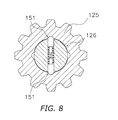
- FIG. 8 is a cross-sectional view of a part of the handle shaft which corresponds to FIG. 6 described in another exemplary embodiment of the present invention.
- a dual-bearing reel is a low profile reel.
- the dual-bearing reel includes a reel unit 1 , a handle 2 for rotating a spool and a spool 12 for winding a fishing line.
- the handle 2 is disposed laterally to (e.g., on the left side of) the reel unit 1 .
- the spool 12 is rotatably and detachably attached to the inside of the reel unit 1 .
- a drag regulation member 3 is disposed on the reel unit 1 side of the handle 2 in order to regulate drag.
- the handle 2 is of a double-handle type including a handle arm 2 a and two knob portions 2 b .
- the handle arm 2 a is a plate-shaped member made of, for instance, metal.
- the knob portions 2 b are rotatably attached to the both ends of the handle arm 2 a .
- the handle arm 2 a is non-rotatably fixed to a tip of a handle shaft 30 by a nut 2 d . Rotation of the nut 2 d is prevented by a retainer 2 c fixed to the outer surface of the handle arm 2 a by a screw.
- the reel unit 1 includes a frame 5 , a first side cover 6 a , a second side cover 6 b , and a shaft support part 7 .
- the first and second side covers 6 a and 6 b are attached to the both lateral sides of the frame 5 for laterally covering the frame 5 .
- the shaft support part 7 is detachably attached to a lateral part of the frame 5 .
- the first side cover 6 a is disposed on the opposite side of the handle 2
- the second side cover 6 b is disposed on the attachment side of the handle 2 .
- the frame 5 is a member made of light metal (e.g., aluminum alloy, magnesium alloy, etc.) and includes a first side plate 5 a , a second side plate 5 b , and a plurality of coupling portions 5 c .
- the first and second side plates 5 a and 5 b are opposed at a predetermined interval.
- the coupling portions 5 c couple the first and second side plates 5 a and 5 b .
- the shaft support part 7 is detachably attached to the first side plate 5 a disposed on the opposite side of the handle attachment side.
- the first side plate 5 a includes a circular opening 5 d for allowing the spool 12 to pass therethrough.
- the shaft support part 7 is detachably attached to the opening 5 d b , for instance, by a bayonet mechanism 23 in order to take out the spool 12 from the opening 5 d side.
- a fishing rod attachment leg 4 is integrally formed with two bottom-side coupling portions 5 c .
- the fishing rod attachment leg 4 is a member elongated back and forth for attaching the dual-bearing reel to a fishing rod.
- the first side cover 6 a is a member made of light metal (e.g., aluminum alloy, magnesium alloy, etc.) and covers the outside of the first side plate 5 a .
- the first side cover 6 a has a circular recess 6 c in the center part thereof.
- the recess 6 c is recessed in a plurality of stages.
- the recess 6 c has a circular knob opening 6 d in the center part thereof.
- the shaft support part 7 is exposed to the outside through the knob opening 6 d .
- the first side cover 6 a is interposed and held by the shaft support part 7 and is thereby detachably attached to the frame 5 together with the shaft support part 7 .
- a positioning mechanism 60 is disposed on the inner peripheral part of the knob opening 6 d of the first side cover 6 a .
- the positioning mechanism 60 is configured to prevent rotation of the shaft support part 7 of a non-operated state and appropriately position the shaft support part 7 of an operated state.
- the second side cover 6 b is a member made of light metal (e.g., aluminum alloy, magnesium alloy, etc.) and is fixed to the second side plate 5 b of the frame 5 by screws.
- the second side cover 6 b includes a boss portion 8 and a lid member 9 .
- the boss portion 8 is disposed in a position where a spool shaft 16 is disposed.
- the lid member 9 closes an opening of the boss portion 8 .
- the boss portion 8 is fixed to the second side cover 6 b , for instance, by swaging.
- the lid member 9 is fixed to the second side cover 6 b by screws.
- the inner diameter of the boss portion 8 is slightly greater than the outer diameter of a gear portion 32 a of a pinion gear 32 to be described. Therefore, the gear portion 32 a can enter the inner peripheral side of the boss portion 8 .
- the shaft support part 7 is rotatably attached to the first side cover 6 a while interposing and holding the first side cover 6 a between components thereof. Therefore, the shaft support part 7 is prevented from being detached from the first side cover 6 a . Further, the shaft support part 7 is detachably attached to the first side plate 5 a by the bayonet mechanism 23 as illustrated in FIG. 3 .
- the bayonet mechanism 23 includes a plurality of (e.g., three) plate-shaped protruding portions 23 a and a plurality of (e.g., three) groove-shaped engaging recesses 23 b .
- the protruding portions 23 a protrude radially outwards from the outer periphery of the shaft support part 7 while being circumferentially aligned at predetermined intervals on the outer periphery of the shaft support part 7 .
- the engaging recesses 23 b are formed outside the opening 5 d of the first side plate 5 a for engaging with the protruding portions 23 a .
- the shaft support part 7 is turned and attached to the first side plate 5 a by the bayonet mechanism 23 . Accordingly, the first side cover 6 a is also attached to the first side plate 5 a.
- the shaft support part 7 includes a bearing mounting portion 33 and an attachment/detachment operating portion 34 .
- the bearing mounting portion 33 is a portion where a first bearing 24 a is mounted.
- the attachment/detachment operating portion 34 together with the bearing mounting portion 33 , interposes and holds the first side cover 6 a therebetween in a relatively rotatable state.
- the bearing mounting portion 33 is a saucer-shaped member.
- An outer periphery 33 a of the bearing mounting portion 33 is fitted into the opening 5 d . Further, the outer periphery 33 a has the plural protruding portions 23 a of the bayonet mechanism 23 .
- the protruding portions 23 a protrude radially outwards from the outer periphery 33 a while being circumferentially aligned about the axis of the spool 12 at predetermined intervals.
- the bearing mounting portion 33 has a tubular bearing accommodation portion 33 b in the center part thereof.
- the bearing accommodation portion 33 b protrudes towards the spool 12 in a tubular shape for accommodating the first bearing 24 a .
- the bearing accommodation portion 33 b has a stepped tubular mounting space 33 c for mounting the first bearing 24 a to the inner peripheral surface thereof.
- a disc-shaped first plate 41 a forming a part of a casting control mechanism 22 to be described, is attached to a bottom portion 33 d of the mounting space 33 c .
- the bottom portion 33 d has a female threaded portion 33 e that a brake knob 42 to be described is screwed.
- the bearing mounting portion 33 has a plurality of (e.g., two) positioning convex portions 33 f on the surface thereof that makes contact with the attachment/detachment operating portion 34 .
- the positioning convex portions 33 f protrude in parallel to the axis of the spool 12 while being circumferentially aligned about the axis of the spool shaft 16 at predetermined intervals.
- the bearing mounting portion 33 has a tubular seal arrangement portion 33 g protruding axially outwards on the outer surface thereof.
- the attachment/detachment operating portion 34 is a stepped cylindrical member fixed to the bearing mounting portion 33 by a screw member (not illustrated in the figures).
- the attachment/detachment operating portion 34 serves to perform an attachment/detachment operation of the shaft support part 7 .
- the outer surface of the attachment/detachment operating portion 34 is slightly recessed than that of the first side cover 6 a .
- the attachment/detachment operating portion 34 has a rib 34 a disposed on the diameter thereof for performing an attachment/detachment operation.
- the rib 34 a has a shape further protruding radially inwards and axially outwards than the other part of the attachment/detachment operating portion 34 .
- the attachment/detachment operating portion 34 has an opening 34 b in the center part thereof.
- the seal arrangement portion 33 g protrudes into the opening 34 b .
- the attachment/detachment operating portion 34 has a plurality of (e.g., two) positioning recesses 34 c on the wall surface thereof (i.e., the bearing mounting portion 33 side wall surface).
- the positioning convex portions 33 f are engaged with the positioning recesses 34 c.
- the frame 5 accommodates the spool 12 for winding a fishing line, a level winding mechanism 15 and a clutch operating member 17 .
- the spool 12 can be disposed along a direction perpendicularly to a fishing rod.
- the level winding mechanism 15 is configured to uniformly wind the fishing line onto the spool 12 .
- the clutch operating member 17 functions as a thumb pad in thumbing the fishing line.
- a gear mechanism 18 , a clutch mechanism 13 , a clutch control mechanism 19 , a drag mechanism 21 and the casting control mechanism 22 are disposed between the frame 5 and the second side cover 6 b .
- the gear mechanism 18 is configured to transfer rotational force from the handle 2 to the spool 12 and the level winding mechanism 15 .
- the clutch control mechanism 19 is configured to execute an on/off control of the clutch mechanism 13 .
- the drag mechanism 21 is configured to brake rotation of the spool 12 in a fishing-line releasing direction.
- the casting control mechanism 22 is configured to regulate resistive force to be applied during rotation of the spool 12 .
- the spool 12 has a pair of saucer-shaped flanges 12 a on the both lateral parts thereof. Further, the spool 12 has a tubular bobbin trunk 12 b between the flanges 12 a . Yet further, the spool 12 has a tubular boss 12 c integrally formed with a substantially axial center part of the inner periphery of the bobbin trunk 12 b .
- the spool 12 is non-rotatably fixed onto the spool shaft 16 penetrating the boss 12 c , for instance, by serration coupling.
- the method of fixing the spool 12 onto the spool shaft 16 is not limited to the serration coupling and a variety of coupling methods (e.g., key coupling, spline coupling, etc.) can be herein employed instead.
- the spool shaft 16 is extended to the second side cover 6 b while penetrating through the second side plate 5 b .
- the spool shaft 16 is rotatably supported by the reel unit 1 through the first bearing 24 a and a second bearing 24 b on the axially both sides of the boss 12 c of the spool 12 .
- the first bearing 24 a is mounted to the shaft support part 7
- the second bearing 24 b is mounted to the second side plate 5 b .
- a first end surface 16 a and a second end surface 16 b of the spool shaft 16 respectively protrude and are formed in either a chevron shape or a circular-arc shape.
- the first and second end surfaces 16 a and 16 b of the spool shaft 16 can make contact with the casting control mechanism 22 .
- An engaging pin 13 a forming a part of the clutch mechanism 13 , is fixed to a part of the spool shaft 16 that penetrates through the second side plate 5 b .
- the engaging pin 13 a penetrates through the spool shaft 16 along its diameter, while the both ends thereof radially protrude from the spool shaft 16 .
- the tip (i.e., the right end in FIG. 2 ) of the pinion gear 32 to be described can be engaged with the both protruding ends of the engaging pin 13 a.
- the level winding mechanism 15 includes a second gear 25 , a traverse cam shaft 26 and a fishing line guide 27 .
- the second gear 25 is meshed with a first gear 28 of the gear mechanism 18 to be described.
- the traverse cam shaft 26 is a shaft member having helical grooves 26 a intersecting with each other on the outer peripheral surface thereof.
- the fishing line guide 27 is a portion that the fishing line is inserted therethrough.
- the fishing line guide 27 is engaged with the helical grooves 26 a .
- the fishing line guide 27 is configured to reciprocate in parallel to and in front of the spool 12 in conjunction with rotation of the traverse cam shaft 26 .
- the fishing line can pass through the fishing line guide 27 and is uniformly wound about the spool 12 in conjunction with reciprocation of the fishing line guide 27 .
- the gear mechanism 18 includes the handle shaft 30 , a driving gear 31 , the pinion gear 32 and the first gear 28 .
- the driving gear 31 is rotatably mounted onto the handle shaft 30 .
- the pinion gear 32 is a tubular gear to be meshed with the driving gear 31 .
- the first gear 28 is meshed with the second gear 25 while being mounted onto the handle shaft 30 .
- the handle shaft 30 is prevented from rotating in the fishing-line releasing direction by a roller-type one-way clutch 40 . In other words, the handle shaft 30 is allowed to rotate only in the fishing-line winding direction.
- the one-way clutch 40 is mounted to the second side cover 6 b .
- the base end of the handle shaft 30 is rotatably supported by the second side plate 5 b through a bearing 20 .
- a ratchet wheel 36 is disposed on the rear side (i.e., the left side in FIG. 3 ) of the driving gear 31 while being mounted onto the handle shaft 30 in a unitarily rotatable state.
- the first gear 28 is disposed on the rear side of the ratchet wheel 36 .
- the handle shaft 30 has a large-diameter contact portion 30 b between its portion for mounting the ratchet wheel 36 and its portion for mounting the first gear 28 . Rotation of the handle shaft 30 is transferred to the driving gear 31 through the drag mechanism 21 .
- the pinion gear 32 is extended axially outwards from the second side plate 5 b .
- the pinion gear 32 is a tubular member that the spool shaft 16 penetrates through the center thereof.
- the pinion gear 32 is mounted onto the spool shaft 16 while being axially movable.
- the pinion gear 32 has the gear portion 32 a , an engaging portion 32 b and a narrowed portion 32 c .
- the gear portion 32 a is formed on the base end of the pinion gear 32 .
- the engaging portion 32 b is formed on the tip end of the pinion gear 32 and can be engaged with the engaging pin 13 a .
- the narrowed portion 32 c is disposed between the gear portion 32 a and the engaging portion 32 b .
- the driving gear 31 is meshed with the gear portion 32 a .
- the engaging pin 13 a is engaged with the engaging portion 32 b .
- a clutch yoke 35 of the clutch control mechanism 19 is engaged with the narrowed portion 32 c .
- the pinion gear 32 is configured to be moved between a clutch-on position illustrated above a center line C in FIG. 3 and a clutch-off position illustrated below the center line C in FIG. 3 in conjunction with either an operation of the clutch operating member 17 or rotation of the handle 2 in the fishing-line winding direction.
- the pinion gear 32 is supported by the second side plate 5 b through a bearing 29 while being rotatable and axially movable.
- the first gear 28 is coupled to the handle shaft 30 through a torque limiter 39 (an exemplary torque limiting device for a fishing reel). As illustrated in FIG. 3 , the first gear 28 is meshed with the second gear 25 mounted onto the traverse cam shaft 26 of the level winding mechanism 15 .
- the torque limiter 39 is provided for preventing excessive force from acting on the first gear 28 (an exemplary rotary member) and the second gear 25 when the level winding mechanism 15 is broken down.
- the torque limiter 39 includes a pair of pin members 51 , an urging member 52 and at least a locking recess 53 .
- the pin members 51 are disposed in the handle shaft 30 (an exemplary shaft member).
- the urging member 52 is, for instance, a coil spring for urging the paired pin members 51 towards the first gear 28 .
- At least one locking recess 53 is formed on the inner peripheral surface of the first gear 28 . In the present exemplary embodiment, four locking recesses 53 are formed thereon while being circumferentially aligned at predetermined intervals.
- the handle shaft 30 includes a through hole 30 a penetrating therethrough in a diameter direction for allowing the pin members 51 to be inserted therein such that the pin members 51 are protrudable and retractable.
- Each pin member 51 has a head portion 51 a and a shaft portion 51 b .
- the head portion 51 a has a curved surface of a hemispheric cannonball shape, while the shaft portion 51 b has a diameter smaller than that of the head portion 51 a .
- the pin members 51 are disposed within the through hole 30 a while the head portions 51 a are directed to the locking recesses 53 .
- the urging member 52 is disposed on the outer peripheral side of the shaft portions 51 b of the paired pin members 51 while being compressed between the paired head portions 51 a .
- Each locking recess 53 has a linear slope 53 a and a cylindrical surface 53 b .
- the slope 53 a is disposed downstream in a rotational direction (i.e., a fishing-line winding direction) of the first gear 28 depicted with an arrow R, while the cylindrical surface 53 b is disposed upstream in the rotation direction of the first gear 28 . Therefore, rotation of the handle shaft 30 is normally transmitted to the first gear 28 when the pin members 51 press the slopes 53 a .
- the pin members 51 are configured to retract into the through hole 30 a when excessive force acts on the first gear 28 by strongly rotating the handle 2 while foreign substance gets stuck in the level winding mechanism 15 . Accordingly, the handle shaft 30 idles and this prevents the first gear 28 from being easily damaged or broken down.
- the contact surface (the slope 53 a and the cylindrical surface 53 b ) of each locking recess 53 which is contactable with one of the head portions 51 a , has a slope 53 c intersecting with the axis of the handle shaft 30 .
- Each slope 53 c is slanted for gradually getting closer to the axis of the handle shaft 30 towards the driving gear 31 .
- the slope 53 c can be formed using the draft angle of a mold. With the structure, force of pressing the first gear 28 towards the contact portion 30 b is produced when the pin members 51 press the first gear 28 . The first gear 28 is thereby prevented from being easily wobbled in its rotation.
- the clutch mechanism 13 includes the engaging pin 13 a and the engaging portion 32 b of the pinion gear 32 .
- the clutch mechanism 13 can be set to be in either of the clutch-on state and the clutch-off state in response to an operation of the clutch operating member 17 .
- rotation of the handle 2 is transmitted to the spool 12 .
- the clutch-off state the spool 12 can be freely rotated.
- the clutch operating member 17 is disposed rearwards of the spool 12 while being disposed in the rear part of the space interposed between the first side plate 5 a and the second side plate 5 b .
- the frame 5 has an elongated hole (not illustrated in the figures) in each of the first and second side plates 5 a and 5 b .
- the clutch operating member 17 is rotatably supported by the elongated holes. Therefore, the clutch operating member 17 can be slid up and down along the elongated holes.
- the clutch control mechanism 19 includes the clutch yoke 35 .
- the clutch yoke 35 is disposed on the outer peripheral side of the spool shaft 16 .
- the clutch yoke 35 is supported by two pins (not illustrated in the figures) while being movable in parallel to the axis of the spool shaft 16 .
- the spool shaft 16 can be rotated relatively to the clutch yoke 35 .
- the clutch yoke 35 is configured not to be rotated even when the spool shaft 16 is rotated.
- the clutch yoke 35 is movable right and left in FIG. 3 while the middle part thereof is engaged with the narrowed portion 32 c of the pinion gear 32 .
- the clutch yoke 35 is constantly urged in a clutch-on direction (i.e., inwards, more specifically, leftwards in FIG. 3 ) by a spring (not illustrated in the figures).
- the pinion gear 32 is normally disposed in the inner clutch-on position while being engaged with the engaging pin 13 a of the spool shaft 16 .
- the clutch-on state is produced.
- the pinion gear 32 is moved outwards by the clutch yoke 35 , on the other hand, engagement between the pinion gear 32 and the engaging pin 13 a is released.
- the gear portion 32 a of the pinion gear 32 is herein disposed on the inner peripheral side of the boss portion 8 as illustrated below an axis C in FIG. 3 . Therefore, the pinion gear 32 is prevented from being easily wobbled in the clutch-off state.
- the drag mechanism 21 includes the drag regulation member 3 , a pressure plate 38 and the one-way clutch 40 .
- the drag regulation member 3 is used for an operation of regulating drag force.
- the pressure plate 38 is mounted onto the handle shaft 30 in a unitarily rotatable state.
- the one-way clutch 40 is mounted to the second side cover 6 b while being disposed in the surrounding of the handle shaft 30 .
- the pressure plate 38 is coupled to an inner race 40 a of the one-way clutch 40 in a unitarily rotatable state.
- slippage is caused between the pressure plate 38 and the driving gear 31 .
- the drag mechanism 21 is thus configured to brake the spool 12 .
- the one-way clutch 40 is configured to prevent the handle shaft 30 from rotating in the fishing-line releasing direction.
- the casting control mechanism 22 includes the first plate 41 a , second plates 41 b and the brake knob 42 .
- the first and second plates 41 a and 41 b are disposed for holding and interposing therebetween the both ends of the spool shaft 16 .
- the brake knob 42 serves to regulate force of the first and second plates 41 a and 41 b for holding and interposing therebetween the spool shaft 16 .
- the single first plate 41 a is disposed on the left side (see FIG. 3 ) while being mounted to the bottom portion 33 d of the mounting space 33 c within the bearing mounting portion 33 .
- the first plate 41 a can make contact with a first end 16 a of the spool shaft 16 .
- the two second plates 41 b are mounted to the inside of the boss portion 8 of the second side cover 6 b.
- the brake knob 42 has an operating portion 42 a , a seal attachment portion 42 b , and a male threaded portion 42 c .
- the operating portion 42 a is a circular portion.
- the seal attachment portion 42 b has a diameter smaller than that of the operating portion 42 a .
- the male threaded portion 42 c has a diameter smaller than that of the seal attachment portion 42 b .
- the operating portion 42 a has a circular truncated cone shape.
- the outer peripheral side of the operating portion 42 a is disposed away from the attachment/detachment operating portion 34 at a clearance produced for operating the operating portion 42 a .
- the brake knob 42 is disposed in the recess 6 c of the first side cover 6 a while being prevented from protruding from the outer surface of the first side cover 6 a .
- the attachment/detachment operating portion 34 is also disposed in the recess 6 c . Therefore, the operating portion 42 a is thus disposed away from the attachment/detachment operating portion 34 at the clearance.
- the seal attachment portion 42 b has an annular seal attachment groove 42 d .
- An O-ring 43 is attached onto the seal attachment groove 42 d .
- the O-ring 43 is disposed for making contact with the inner peripheral surface of the seal arrangement portion 33 g and the seal attachment groove 42 d .
- the male threaded portion 42 c is screwed into the female threaded portion 33 e of the bearing mounting portion 33 .
- the male threaded portion 42 c can make contact with the first plate 41 a.
- the clutch yoke 35 is normally pressed inwards (leftwards in FIG. 3 ).
- the pinion gear 32 is thereby moved to an engaged position.
- the clutch-on state is herein produced, while the pinion gear 32 and the engaging pin 13 a of the spool shaft 16 are meshed.
- Rotational force from the handle 2 is herein transmitted to the spool 12 through the handle shaft 30 , the driving gear 31 , the pinion gear 32 , and the spool shaft 16 .
- the spool 12 is accordingly rotated in the fishing-line winding direction.
- braking force is regulated by the casting control mechanism 22 for inhibiting occurrence of backlash.
- the brake knob 42 is turned in the clockwise direction, for instance. The brake knob 42 thereby proceeds rightwards in FIG. 5 and the interval between the first plate 41 a and the second plates 41 b is reduced. Accordingly, braking force onto the spool shaft 16 is increased. In contrast, braking force is reduced by turning the brake knob 42 in the counterclockwise direction.
- the clutch operating member 17 When regulation of braking force is finished, the clutch operating member 17 is pressed downwards.
- the clutch operating member 17 is herein moved to a downward disengaged position. Further, the clutch yoke 35 is moved outwards in conjunction with movement of the clutch operating member 17 .
- the pinion gear 32 engaged with the clutch yoke 35 , is also moved in the same direction as the clutch yoke 35 .
- engagement between the pinion gear 32 and the engaging pin 13 a of the spool shaft 16 is released and the clutch-off state is thereby produced.
- rotation from the handle shaft 30 is not transmitted to the spool 12 and the spool shaft 16 . Therefore, the spool 12 can be freely rotated.
- an angler drops the fishing line by tilting the reel for arranging the spool shaft 16 along a vertical plane while thumbing the fishing line wound about the spool 12 by the thumb of the hand holding and palming the first side cover 6 a .
- the spool 12 is accordingly rotated in the fishing-line releasing direction by the weight of a terminal tackle and the fishing line is reeled out.
- the brake knob 42 is herein disposed in the recess 6 c of the first side cover 6 a disposed oppositely to the handle 2 attachment side while being prevented from protruding from the first side cover 6 a . Therefore, the brake knob 42 does not make contact with the angler's palm even when palming is executed on the first side cover 6 a side. With the structure, palming can be easily executed on the opposite side of the handle 2 attachment side.
- the handle 2 is rotated in the fishing-line winding direction when a fish bites after the fishing line is reeled out.
- rotation is transmitted from the first gear 28 to the second gear 25 , and the fishing line guide 27 of the level winding mechanism 15 is reciprocated in front of the spool 12 along the spool shaft direction.
- the fishing line is uniformly wound about the spool 12 .
- the fishing line guide 27 can become immovable due to a factor such as attachment of foreign material onto the traverse cam shaft 26 .
- large torque acts on the first gear 28 and the second gear 25 .
- the pin members 51 retract into the through hole 30 a against the urging force of the urging member 52 , and the handle shaft 30 is rotated with respect to the first gear 28 . Accordingly, torque is restricted from being transmitted from the handle shaft 30 to the first gear 28 .
- members for restricting transmission torque i.e., the pin members 51 and the urging member 52 are disposed on the handle shaft 30 , and it is only required to form at least one locking recess 53 on the first gear 28 . Therefore, the first gear 28 can be compactly formed.
- the torque limiter 39 as a torque limiting device is a device configured to limit torque between the handle shaft 30 as a rotatable shaft member and the first gear 28 as a rotary member disposed on the outer peripheral side of the handle shaft 30 .
- the torque limiter 39 includes at least one pin member 51 , at least one urging member 52 and at least one locking recess 53 .
- At least one pin member 51 is a member with a spherical tip. The pin member 51 can be protruding towards and retracting from the first gear 28 while being disposed in the handle shaft 30 .
- At least one urging member 52 is disposed in the handle shaft 30 and urges the pin member 51 towards the first gear 28 .
- At least one locking recess 53 is formed on the first gear 28 for allowing the tip of the pin member 51 to be engaged therewith.
- the tip (i.e., the head portion 51 a ) of the pin member 51 is normally engaged with the locking recess 53 while the pin member 51 is urged towards the first gear 28 by the urging member 52 . Accordingly, rotation is transmitted from the handle shaft 30 to the first gear 28 or vice versa.
- torque to be transmitted exceeds allowable torque set in accordance with the urging force of the urging member 52
- the pin member 51 retracts into the through hole 30 a of the handle shaft 30 against the urging force of the urging member 52 . Accordingly, the first gear 28 and the handle shaft 30 can be rotated relatively to each other. Accordingly, torque to be transmitted is restricted.
- members for restricting transmission torque i.e., the pin member 51 and the urging member 52 are disposed on the handle shaft 30 , and it is only required to form at least one locking recess 53 on the first gear 28 . Therefore, the first gear 28 can be compactly formed.
- the pin member 51 has the head portion 51 a having a spherical tip and the shaft portion 51 b having a diameter smaller than that of the head portion 51 a .
- the urging member 52 formed in a coil spring shape can be compactly disposed on the outer peripheral side of each small-diameter shaft portion 51 b.
- the two pin members 51 are disposed along the diameter of the handle shaft 30 while the head portions 51 a thereof are directed radially outwards.
- one urging member 52 is disposed.
- the urging member 52 is a coil spring disposed on the outer peripheral side of the two shaft portions 51 b while being disposed between the two head portions 51 a.
- the two pin members 51 can be urged by a single coil spring using a step produced in each pin member 51 between the head portion 51 a and the small-diameter shaft portion 51 b . Therefore, the diameter of the handle shaft 30 can be reduced. Further, the pin members 51 and the urging member 52 can be easily accommodated only by forming the through hole 30 a along the diameter of the handle shaft 30 .
- the locking recesses 53 are circumferentially aligned at predetermined intervals. In this case, even when two pin members 51 are provided, the pin members 51 can protrude into the next locking recesses 53 in the rotational direction when transmission torque is reduced.
- the rotary member is a gear member configured to transmit rotation of the handle shaft to the traverse cam shaft of the level winding mechanism.
- the first gear 28 configured to transmit rotation to the traverse cam shaft of the level winding mechanism or the second gear 25 .
- the shaft member is the handle shaft 30 of the dual-bearing reel that is prevented from rotating in the fishing-line releasing direction.
- the first gear 28 to be mounted on the handle shaft 30 can be compactly formed.
- the shaft member is the traverse cam shaft 26 .
- the second gear 25 to be mounted on the traverse cam shaft 26 can be compactly formed.
- the handle shaft 30 has been exemplified as a shaft member while the first gear 28 has been exemplified as a rotary member.
- the spool shaft and the traverse cam shaft can be set as shaft members.
- a pin member 151 can be disposed in the traverse cam shaft 126 having a diameter greater than that of the spools shaft. In this case, torque to be transmitted from the intermediate gear 125 to the traverse cam shaft 126 is restricted.
- a manual dual-bearing reel has been exemplified.
- the present invention can be applied to an electric dual-bearing reel.
- the present invention can be applied to a dual-bearing reel with a handle configured to be rotated in the fishing-line releasing direction.
- the right handled dual-bearing reel has been exemplified.
- the present invention can be also applied to a left handled dual-bearing reel.
- the slope 53 a and the cylindrical surface 53 b are provided as the contact surface of the locking recess 53 .
- the contact surface of the locking recess 53 can be formed by either of the slope 53 a and the cylindrical surface 53 b .
- slopes can be formed on the both sides of the locking recess.
- cylindrical surfaces can be formed on the both sides of the locking recess.
- a pin member and an urging member, configured to limit transmission torque are disposed on a shaft member and a recess is only required to be formed on a rotary member. Therefore, the rotary member can be compactly formed.
- the term “comprising” and its derivatives, as used herein, are intended to be open ended terms that specify the presence of the stated features, elements, components, groups, integers, and/or steps, but do not exclude the presence of other unstated features, elements, components, groups, integers and/or steps.
- the foregoing also applies to words having similar meanings such as the terms, “including”, “having” and their derivatives.
- the terms “part,” “section,” “portion,” “member” or “element” when used in the singular can have the dual meaning of a single part or a plurality of parts.
Applications Claiming Priority (2)
| Application Number | Priority Date | Filing Date | Title |
|---|---|---|---|
| JP2011-211082 | 2011-09-27 | ||
| JP2011211082A JP5912371B2 (ja) | 2011-09-27 | 2011-09-27 | 釣り用リールのトルク制限装置 |
Publications (2)
| Publication Number | Publication Date |
|---|---|
| US20130075218A1 US20130075218A1 (en) | 2013-03-28 |
| US8882013B2 true US8882013B2 (en) | 2014-11-11 |
Family
ID=47910031
Family Applications (1)
| Application Number | Title | Priority Date | Filing Date |
|---|---|---|---|
| US13/567,600 Active 2032-12-22 US8882013B2 (en) | 2011-09-27 | 2012-08-06 | Torque limiting device for fishing reel |
Country Status (6)
| Country | Link |
|---|---|
| US (1) | US8882013B2 (zh) |
| JP (1) | JP5912371B2 (zh) |
| KR (1) | KR101975425B1 (zh) |
| CN (1) | CN103070146B (zh) |
| MY (1) | MY167832A (zh) |
| TW (1) | TWI613964B (zh) |
Cited By (1)
| Publication number | Priority date | Publication date | Assignee | Title |
|---|---|---|---|---|
| KR20160149502A (ko) * | 2015-06-18 | 2016-12-28 | 두산중공업 주식회사 | 토크 리미터 및 복수 개의 피니언 기어를 포함하는 요 드라이브 |
Families Citing this family (11)
| Publication number | Priority date | Publication date | Assignee | Title |
|---|---|---|---|---|
| JP6376740B2 (ja) * | 2013-10-01 | 2018-08-22 | 株式会社シマノ | 両軸受リール |
| JP6352756B2 (ja) | 2014-09-30 | 2018-07-04 | 株式会社シマノ | 釣用リールのトルク制限装置 |
| JP6656813B2 (ja) * | 2015-03-10 | 2020-03-04 | 株式会社シマノ | 釣り用リールの往復移動機構及び釣り用リール |
| JP2018113919A (ja) * | 2017-01-19 | 2018-07-26 | 株式会社シマノ | 両軸受リール |
| CN107725634A (zh) * | 2017-11-07 | 2018-02-23 | 陈桂音 | 一种根据扭矩恢复连接的扭矩限制器 |
| JP7084736B2 (ja) * | 2018-02-01 | 2022-06-15 | 株式会社シマノ | 両軸受リール |
| JP7032225B2 (ja) | 2018-04-26 | 2022-03-08 | シマノコンポネンツ マレーシア エスディーエヌ.ビーエッチディー. | 釣り用リールのトルク制限装置、及びスピニングリール |
| JP7082901B2 (ja) * | 2018-04-26 | 2022-06-09 | シマノコンポネンツ マレーシア エスディーエヌ.ビーエッチディー. | 両軸受リール |
| JP7114070B2 (ja) * | 2018-10-12 | 2022-08-08 | 株式会社東和電機製作所 | 釣り機 |
| JP7412294B2 (ja) * | 2020-07-06 | 2024-01-12 | 株式会社シマノ | 釣り用リールのトルク制限装置及び釣り用リール |
| JP2022068656A (ja) | 2020-10-22 | 2022-05-10 | 株式会社シマノ | 釣り用リールのトルク制限装置及び釣り用リール |
Citations (8)
| Publication number | Priority date | Publication date | Assignee | Title |
|---|---|---|---|---|
| US2523134A (en) | 1946-10-05 | 1950-09-19 | Emma C Maynes | Fishing reel |
| US2768547A (en) * | 1954-04-28 | 1956-10-30 | Printing Machinery Company | Predetermined torque release hand tool |
| US3958469A (en) * | 1975-10-14 | 1976-05-25 | Emerson Electric Co. | Torque wrench |
| US4238978A (en) * | 1979-03-16 | 1980-12-16 | Lowell Corporation | Torque wrench |
| US5954285A (en) * | 1996-11-06 | 1999-09-21 | Whisenhunt; Kelsie C. | Driving arrangement for a motorized fishing reel |
| US6422497B1 (en) * | 1999-09-02 | 2002-07-23 | Toyo Engineering Co., Ltd. | Dual-bearing reel having a detachable handle |
| US7343824B2 (en) * | 2006-06-20 | 2008-03-18 | Bradshaw Medical, Inc. | Variable torque-limiting driver |
| US7913594B2 (en) * | 2002-01-16 | 2011-03-29 | Gauthier Biomedical, Inc. | Ratcheting torque wrench |
Family Cites Families (14)
| Publication number | Priority date | Publication date | Assignee | Title |
|---|---|---|---|---|
| US4815676A (en) * | 1986-09-29 | 1989-03-28 | Charles C. Worth Corporation | Fishing reel handle with drag adjustment incorporated |
| JPH06238574A (ja) * | 1992-12-16 | 1994-08-30 | Zojirushi Chain Block Kk | 定トルク締付具 |
| JP2569622Y2 (ja) * | 1993-08-19 | 1998-04-28 | ダイワ精工株式会社 | 魚釣用両軸受型リールの釣糸案内装置 |
| US5810273A (en) * | 1995-11-30 | 1998-09-22 | Zebco Div. Of Brunswick Corporation | Antijamming mechanism for a fishing reel |
| JP3542284B2 (ja) * | 1998-09-08 | 2004-07-14 | シマノ シンガポール ピーティーイー.リミテッド. | 釣り用リール |
| JP2000342131A (ja) * | 1999-06-04 | 2000-12-12 | Atsushi Monju | 魚釣り用リールのハンドル |
| JP2001263364A (ja) * | 2000-03-15 | 2001-09-26 | Seibu Electric & Mach Co Ltd | トルクリミッタ |
| CN2520104Y (zh) * | 2002-01-25 | 2002-11-13 | 上海达金兴业渔具有限公司 | 一种钓鱼卷线器 |
| JP4011400B2 (ja) * | 2002-05-17 | 2007-11-21 | ダイワ精工株式会社 | 魚釣用スピニングリ−ル |
| JP2004242542A (ja) * | 2003-02-12 | 2004-09-02 | Daiwa Seiko Inc | 魚釣用リール |
| DE102004035000A1 (de) * | 2004-02-20 | 2005-09-08 | Helmut Klein | Handkurbel für eine Rolleneinheit zur Verwendung bei einer Angel sowie Rolleneinheit mit einer solchen Kurbel |
| TWI271149B (en) * | 2005-03-25 | 2007-01-21 | Daiwa Seiko Inc | Spinning reel for fishing |
| JP5008321B2 (ja) * | 2005-09-07 | 2012-08-22 | 株式会社シマノ | スピニングリールの往復移動機構 |
| CN201830781U (zh) * | 2010-09-21 | 2011-05-18 | 蔡曜竹 | 光渔线轮 |
-
2011
- 2011-09-27 JP JP2011211082A patent/JP5912371B2/ja active Active
-
2012
- 2012-08-06 US US13/567,600 patent/US8882013B2/en active Active
- 2012-08-16 MY MYPI2012700560A patent/MY167832A/en unknown
- 2012-08-23 TW TW101130658A patent/TWI613964B/zh active
- 2012-08-28 KR KR1020120094146A patent/KR101975425B1/ko active IP Right Grant
- 2012-09-27 CN CN201210373424.3A patent/CN103070146B/zh active Active
Patent Citations (9)
| Publication number | Priority date | Publication date | Assignee | Title |
|---|---|---|---|---|
| US2523134A (en) | 1946-10-05 | 1950-09-19 | Emma C Maynes | Fishing reel |
| US2768547A (en) * | 1954-04-28 | 1956-10-30 | Printing Machinery Company | Predetermined torque release hand tool |
| US3958469A (en) * | 1975-10-14 | 1976-05-25 | Emerson Electric Co. | Torque wrench |
| US4238978A (en) * | 1979-03-16 | 1980-12-16 | Lowell Corporation | Torque wrench |
| US5954285A (en) * | 1996-11-06 | 1999-09-21 | Whisenhunt; Kelsie C. | Driving arrangement for a motorized fishing reel |
| US6422497B1 (en) * | 1999-09-02 | 2002-07-23 | Toyo Engineering Co., Ltd. | Dual-bearing reel having a detachable handle |
| US7913594B2 (en) * | 2002-01-16 | 2011-03-29 | Gauthier Biomedical, Inc. | Ratcheting torque wrench |
| US7389700B2 (en) * | 2006-04-21 | 2008-06-24 | Bradshaw Medical, Inc. | Variable torque-limiting driver |
| US7343824B2 (en) * | 2006-06-20 | 2008-03-18 | Bradshaw Medical, Inc. | Variable torque-limiting driver |
Cited By (1)
| Publication number | Priority date | Publication date | Assignee | Title |
|---|---|---|---|---|
| KR20160149502A (ko) * | 2015-06-18 | 2016-12-28 | 두산중공업 주식회사 | 토크 리미터 및 복수 개의 피니언 기어를 포함하는 요 드라이브 |
Also Published As
| Publication number | Publication date |
|---|---|
| CN103070146B (zh) | 2016-11-23 |
| CN103070146A (zh) | 2013-05-01 |
| TW201330771A (zh) | 2013-08-01 |
| US20130075218A1 (en) | 2013-03-28 |
| MY167832A (en) | 2018-09-26 |
| KR101975425B1 (ko) | 2019-05-07 |
| KR20130033953A (ko) | 2013-04-04 |
| JP2013070652A (ja) | 2013-04-22 |
| TWI613964B (zh) | 2018-02-11 |
| JP5912371B2 (ja) | 2016-04-27 |
Similar Documents
| Publication | Publication Date | Title |
|---|---|---|
| US8882013B2 (en) | Torque limiting device for fishing reel | |
| US8820669B2 (en) | Dual-bearing reel | |
| US8840053B2 (en) | Handle assembly for dual-bearing reel and dual-bearing reel | |
| EP2517559B1 (en) | Centrifugal brake device for dual-bearing reel | |
| US8550392B2 (en) | Dual-bearing reel clutch control device | |
| US9439408B2 (en) | Dual-bearing reel | |
| US8820670B2 (en) | Dual-bearing reel | |
| US8678308B2 (en) | Dual-bearing reel drag sound producing device | |
| JP2013070652A5 (zh) | ||
| KR101010970B1 (ko) | 양 베어링 릴의 클러치 조작 부재 | |
| US8657222B2 (en) | Drag mechanism for dual-bearing reel | |
| US20130306777A1 (en) | Spool brake device for dual-bearing reel and a dual-bearing reel | |
| EP2957171B1 (en) | Dual-bearing reel and clutch mechanism thereof | |
| US9089118B2 (en) | Drive gear | |
| US9210922B2 (en) | Dual-bearing reel | |
| US8534584B2 (en) | Dual-bearing reel speed change operation mechanism | |
| JP2013070651A5 (zh) | ||
| JP2013106543A5 (zh) | ||
| US9723825B2 (en) | Fishing reel drive gear and fishing reel pinion gear meshed with same |
Legal Events
| Date | Code | Title | Description |
|---|---|---|---|
| AS | Assignment |
Owner name: SHIMANO INC., JAPAN Free format text: ASSIGNMENT OF ASSIGNORS INTEREST;ASSIGNOR:TAKECHI, KUNIO;REEL/FRAME:028731/0427 Effective date: 20120720 |
|
| STCF | Information on status: patent grant |
Free format text: PATENTED CASE |
|
| MAFP | Maintenance fee payment |
Free format text: PAYMENT OF MAINTENANCE FEE, 4TH YEAR, LARGE ENTITY (ORIGINAL EVENT CODE: M1551) Year of fee payment: 4 |
|
| MAFP | Maintenance fee payment |
Free format text: PAYMENT OF MAINTENANCE FEE, 8TH YEAR, LARGE ENTITY (ORIGINAL EVENT CODE: M1552); ENTITY STATUS OF PATENT OWNER: LARGE ENTITY Year of fee payment: 8 |