US8876698B2 - Pressing member, endoscopic treatment system, and endoscopic suturing device - Google Patents
Pressing member, endoscopic treatment system, and endoscopic suturing device Download PDFInfo
- Publication number
- US8876698B2 US8876698B2 US11/996,447 US99644706A US8876698B2 US 8876698 B2 US8876698 B2 US 8876698B2 US 99644706 A US99644706 A US 99644706A US 8876698 B2 US8876698 B2 US 8876698B2
- Authority
- US
- United States
- Prior art keywords
- pressing member
- treatment target
- endoscope
- target portion
- main body
- Prior art date
- Legal status (The legal status is an assumption and is not a legal conclusion. Google has not performed a legal analysis and makes no representation as to the accuracy of the status listed.)
- Active, expires
Links
Images


Classifications
-
- A—HUMAN NECESSITIES
- A61—MEDICAL OR VETERINARY SCIENCE; HYGIENE
- A61B—DIAGNOSIS; SURGERY; IDENTIFICATION
- A61B17/00—Surgical instruments, devices or methods, e.g. tourniquets
- A61B17/32—Surgical cutting instruments
- A61B17/3205—Excision instruments
- A61B17/32056—Surgical snare instruments
-
- A—HUMAN NECESSITIES
- A61—MEDICAL OR VETERINARY SCIENCE; HYGIENE
- A61B—DIAGNOSIS; SURGERY; IDENTIFICATION
- A61B17/00—Surgical instruments, devices or methods, e.g. tourniquets
- A61B17/04—Surgical instruments, devices or methods, e.g. tourniquets for suturing wounds; Holders or packages for needles or suture materials
- A61B17/0401—Suture anchors, buttons or pledgets, i.e. means for attaching sutures to bone, cartilage or soft tissue; Instruments for applying or removing suture anchors
-
- A—HUMAN NECESSITIES
- A61—MEDICAL OR VETERINARY SCIENCE; HYGIENE
- A61B—DIAGNOSIS; SURGERY; IDENTIFICATION
- A61B17/00—Surgical instruments, devices or methods, e.g. tourniquets
- A61B17/04—Surgical instruments, devices or methods, e.g. tourniquets for suturing wounds; Holders or packages for needles or suture materials
- A61B17/0469—Suturing instruments for use in minimally invasive surgery, e.g. endoscopic surgery
-
- A—HUMAN NECESSITIES
- A61—MEDICAL OR VETERINARY SCIENCE; HYGIENE
- A61B—DIAGNOSIS; SURGERY; IDENTIFICATION
- A61B17/00—Surgical instruments, devices or methods, e.g. tourniquets
- A61B17/04—Surgical instruments, devices or methods, e.g. tourniquets for suturing wounds; Holders or packages for needles or suture materials
- A61B17/0482—Needle or suture guides
-
- A—HUMAN NECESSITIES
- A61—MEDICAL OR VETERINARY SCIENCE; HYGIENE
- A61B—DIAGNOSIS; SURGERY; IDENTIFICATION
- A61B17/00—Surgical instruments, devices or methods, e.g. tourniquets
- A61B17/04—Surgical instruments, devices or methods, e.g. tourniquets for suturing wounds; Holders or packages for needles or suture materials
- A61B17/0487—Suture clamps, clips or locks, e.g. for replacing suture knots; Instruments for applying or removing suture clamps, clips or locks
-
- A—HUMAN NECESSITIES
- A61—MEDICAL OR VETERINARY SCIENCE; HYGIENE
- A61B—DIAGNOSIS; SURGERY; IDENTIFICATION
- A61B17/00—Surgical instruments, devices or methods, e.g. tourniquets
- A61B17/04—Surgical instruments, devices or methods, e.g. tourniquets for suturing wounds; Holders or packages for needles or suture materials
- A61B17/06—Needles ; Sutures; Needle-suture combinations; Holders or packages for needles or suture materials
- A61B17/062—Needle manipulators
-
- A—HUMAN NECESSITIES
- A61—MEDICAL OR VETERINARY SCIENCE; HYGIENE
- A61B—DIAGNOSIS; SURGERY; IDENTIFICATION
- A61B17/00—Surgical instruments, devices or methods, e.g. tourniquets
- A61B17/28—Surgical forceps
- A61B17/29—Forceps for use in minimally invasive surgery
-
- A—HUMAN NECESSITIES
- A61—MEDICAL OR VETERINARY SCIENCE; HYGIENE
- A61B—DIAGNOSIS; SURGERY; IDENTIFICATION
- A61B17/00—Surgical instruments, devices or methods, e.g. tourniquets
- A61B17/02—Surgical instruments, devices or methods, e.g. tourniquets for holding wounds open; Tractors
- A61B17/0218—Surgical instruments, devices or methods, e.g. tourniquets for holding wounds open; Tractors for minimally invasive surgery
-
- A—HUMAN NECESSITIES
- A61—MEDICAL OR VETERINARY SCIENCE; HYGIENE
- A61B—DIAGNOSIS; SURGERY; IDENTIFICATION
- A61B18/00—Surgical instruments, devices or methods for transferring non-mechanical forms of energy to or from the body
- A61B18/04—Surgical instruments, devices or methods for transferring non-mechanical forms of energy to or from the body by heating
- A61B18/12—Surgical instruments, devices or methods for transferring non-mechanical forms of energy to or from the body by heating by passing a current through the tissue to be heated, e.g. high-frequency current
- A61B18/14—Probes or electrodes therefor
- A61B18/1477—Needle-like probes
-
- A—HUMAN NECESSITIES
- A61—MEDICAL OR VETERINARY SCIENCE; HYGIENE
- A61B—DIAGNOSIS; SURGERY; IDENTIFICATION
- A61B18/00—Surgical instruments, devices or methods for transferring non-mechanical forms of energy to or from the body
- A61B18/04—Surgical instruments, devices or methods for transferring non-mechanical forms of energy to or from the body by heating
- A61B18/12—Surgical instruments, devices or methods for transferring non-mechanical forms of energy to or from the body by heating by passing a current through the tissue to be heated, e.g. high-frequency current
- A61B18/14—Probes or electrodes therefor
- A61B18/1492—Probes or electrodes therefor having a flexible, catheter-like structure, e.g. for heart ablation
-
- A—HUMAN NECESSITIES
- A61—MEDICAL OR VETERINARY SCIENCE; HYGIENE
- A61B—DIAGNOSIS; SURGERY; IDENTIFICATION
- A61B17/00—Surgical instruments, devices or methods, e.g. tourniquets
- A61B17/00234—Surgical instruments, devices or methods, e.g. tourniquets for minimally invasive surgery
- A61B2017/00238—Type of minimally invasive operation
- A61B2017/00269—Type of minimally invasive operation endoscopic mucosal resection EMR
-
- A—HUMAN NECESSITIES
- A61—MEDICAL OR VETERINARY SCIENCE; HYGIENE
- A61B—DIAGNOSIS; SURGERY; IDENTIFICATION
- A61B17/00—Surgical instruments, devices or methods, e.g. tourniquets
- A61B17/00234—Surgical instruments, devices or methods, e.g. tourniquets for minimally invasive surgery
- A61B2017/00292—Surgical instruments, devices or methods, e.g. tourniquets for minimally invasive surgery mounted on or guided by flexible, e.g. catheter-like, means
- A61B2017/00296—Surgical instruments, devices or methods, e.g. tourniquets for minimally invasive surgery mounted on or guided by flexible, e.g. catheter-like, means mounted on an endoscope
-
- A—HUMAN NECESSITIES
- A61—MEDICAL OR VETERINARY SCIENCE; HYGIENE
- A61B—DIAGNOSIS; SURGERY; IDENTIFICATION
- A61B17/00—Surgical instruments, devices or methods, e.g. tourniquets
- A61B2017/00535—Surgical instruments, devices or methods, e.g. tourniquets pneumatically or hydraulically operated
- A61B2017/00557—Surgical instruments, devices or methods, e.g. tourniquets pneumatically or hydraulically operated inflatable
-
- A—HUMAN NECESSITIES
- A61—MEDICAL OR VETERINARY SCIENCE; HYGIENE
- A61B—DIAGNOSIS; SURGERY; IDENTIFICATION
- A61B17/00—Surgical instruments, devices or methods, e.g. tourniquets
- A61B17/04—Surgical instruments, devices or methods, e.g. tourniquets for suturing wounds; Holders or packages for needles or suture materials
- A61B17/0401—Suture anchors, buttons or pledgets, i.e. means for attaching sutures to bone, cartilage or soft tissue; Instruments for applying or removing suture anchors
- A61B2017/0409—Instruments for applying suture anchors
-
- A—HUMAN NECESSITIES
- A61—MEDICAL OR VETERINARY SCIENCE; HYGIENE
- A61B—DIAGNOSIS; SURGERY; IDENTIFICATION
- A61B17/00—Surgical instruments, devices or methods, e.g. tourniquets
- A61B17/04—Surgical instruments, devices or methods, e.g. tourniquets for suturing wounds; Holders or packages for needles or suture materials
- A61B17/0401—Suture anchors, buttons or pledgets, i.e. means for attaching sutures to bone, cartilage or soft tissue; Instruments for applying or removing suture anchors
- A61B2017/0417—T-fasteners
-
- A—HUMAN NECESSITIES
- A61—MEDICAL OR VETERINARY SCIENCE; HYGIENE
- A61B—DIAGNOSIS; SURGERY; IDENTIFICATION
- A61B17/00—Surgical instruments, devices or methods, e.g. tourniquets
- A61B17/04—Surgical instruments, devices or methods, e.g. tourniquets for suturing wounds; Holders or packages for needles or suture materials
- A61B17/0401—Suture anchors, buttons or pledgets, i.e. means for attaching sutures to bone, cartilage or soft tissue; Instruments for applying or removing suture anchors
- A61B2017/0446—Means for attaching and blocking the suture in the suture anchor
- A61B2017/0448—Additional elements on or within the anchor
- A61B2017/0451—Cams or wedges holding the suture by friction
-
- A—HUMAN NECESSITIES
- A61—MEDICAL OR VETERINARY SCIENCE; HYGIENE
- A61B—DIAGNOSIS; SURGERY; IDENTIFICATION
- A61B17/00—Surgical instruments, devices or methods, e.g. tourniquets
- A61B17/04—Surgical instruments, devices or methods, e.g. tourniquets for suturing wounds; Holders or packages for needles or suture materials
- A61B17/0401—Suture anchors, buttons or pledgets, i.e. means for attaching sutures to bone, cartilage or soft tissue; Instruments for applying or removing suture anchors
- A61B2017/0446—Means for attaching and blocking the suture in the suture anchor
- A61B2017/0458—Longitudinal through hole, e.g. suture blocked by a distal suture knot
-
- A—HUMAN NECESSITIES
- A61—MEDICAL OR VETERINARY SCIENCE; HYGIENE
- A61B—DIAGNOSIS; SURGERY; IDENTIFICATION
- A61B17/00—Surgical instruments, devices or methods, e.g. tourniquets
- A61B17/04—Surgical instruments, devices or methods, e.g. tourniquets for suturing wounds; Holders or packages for needles or suture materials
- A61B17/0401—Suture anchors, buttons or pledgets, i.e. means for attaching sutures to bone, cartilage or soft tissue; Instruments for applying or removing suture anchors
- A61B2017/0464—Suture anchors, buttons or pledgets, i.e. means for attaching sutures to bone, cartilage or soft tissue; Instruments for applying or removing suture anchors for soft tissue
-
- A—HUMAN NECESSITIES
- A61—MEDICAL OR VETERINARY SCIENCE; HYGIENE
- A61B—DIAGNOSIS; SURGERY; IDENTIFICATION
- A61B17/00—Surgical instruments, devices or methods, e.g. tourniquets
- A61B17/04—Surgical instruments, devices or methods, e.g. tourniquets for suturing wounds; Holders or packages for needles or suture materials
- A61B2017/0496—Surgical instruments, devices or methods, e.g. tourniquets for suturing wounds; Holders or packages for needles or suture materials for tensioning sutures
-
- A—HUMAN NECESSITIES
- A61—MEDICAL OR VETERINARY SCIENCE; HYGIENE
- A61B—DIAGNOSIS; SURGERY; IDENTIFICATION
- A61B17/00—Surgical instruments, devices or methods, e.g. tourniquets
- A61B17/04—Surgical instruments, devices or methods, e.g. tourniquets for suturing wounds; Holders or packages for needles or suture materials
- A61B17/06—Needles ; Sutures; Needle-suture combinations; Holders or packages for needles or suture materials
- A61B2017/06052—Needle-suture combinations in which a suture is extending inside a hollow tubular needle, e.g. over the entire length of the needle
-
- A—HUMAN NECESSITIES
- A61—MEDICAL OR VETERINARY SCIENCE; HYGIENE
- A61B—DIAGNOSIS; SURGERY; IDENTIFICATION
- A61B17/00—Surgical instruments, devices or methods, e.g. tourniquets
- A61B17/28—Surgical forceps
- A61B17/29—Forceps for use in minimally invasive surgery
- A61B2017/2926—Details of heads or jaws
-
- A—HUMAN NECESSITIES
- A61—MEDICAL OR VETERINARY SCIENCE; HYGIENE
- A61B—DIAGNOSIS; SURGERY; IDENTIFICATION
- A61B18/00—Surgical instruments, devices or methods for transferring non-mechanical forms of energy to or from the body
- A61B18/04—Surgical instruments, devices or methods for transferring non-mechanical forms of energy to or from the body by heating
- A61B18/12—Surgical instruments, devices or methods for transferring non-mechanical forms of energy to or from the body by heating by passing a current through the tissue to be heated, e.g. high-frequency current
- A61B18/14—Probes or electrodes therefor
- A61B2018/1405—Electrodes having a specific shape
- A61B2018/1407—Loop
- A61B2018/141—Snare
-
- A—HUMAN NECESSITIES
- A61—MEDICAL OR VETERINARY SCIENCE; HYGIENE
- A61B—DIAGNOSIS; SURGERY; IDENTIFICATION
- A61B18/00—Surgical instruments, devices or methods for transferring non-mechanical forms of energy to or from the body
- A61B18/04—Surgical instruments, devices or methods for transferring non-mechanical forms of energy to or from the body by heating
- A61B18/12—Surgical instruments, devices or methods for transferring non-mechanical forms of energy to or from the body by heating by passing a current through the tissue to be heated, e.g. high-frequency current
- A61B18/14—Probes or electrodes therefor
- A61B2018/1405—Electrodes having a specific shape
- A61B2018/1425—Needle
Definitions
- the present invention relates to a pressing member that is inserted into the body and presses a biological tissue when performing an endoscopic treatment and to an endoscopic treatment system having the pressing member.
- the present invention also relates to an endoscopic suturing device that sutures a biological tissue.
- an endoscopic mucosal resection operation When performing a treatment on an alimentary tract affected by cancer or the like within a human body, an endoscopic mucosal resection operation has been conducted in which an endoscope is inserted into the body through the mouth or the anus so as to resect a lesion. In such an operation, all layers including the affected mucosal layer and the muscular layer have been resected. However, perforations may be formed in the alimentary tract by resecting the entire layer. Thus, it is necessary to suture the perforations using an endoscopic treatment system including a suturing device in order to prevent the lumen of the alimentary tract from coalescing with the abdominal cavity via the perforations.
- An endoscopic treatment system employed in such a case is provided with an overtube through which an endoscope can be inserted.
- the overtube has a lateral opening formed at the distal end thereof, through which all layers including the lesion are drawn and are subjected to a suture treatment. Thereafter, all layers are resected by a high-frequency snare or the like.
- a ligating tool or a suture thread
- the tract including the lesion is deformed like a pouch.
- JP-A-2004-65679 is an example of the prior art.
- the opening is formed on the lateral surface of the overtube, it is difficult to capture the image of the lesion using an image capturing portion provided at the distal end of the endoscope. Thus, it is difficult to identify the position of the lesion, deteriorating the operability of a treatment tool such as the suturing device.
- the ligating tool or the suture thread is passed through the alimentary tract so as to substantially overlap with the same, it is difficult to maintain a closed environment until the biological tissue is coalesced.
- the present invention has been made in view of the above-mentioned circumstances, and a main object of the present invention is to facilitate a procedure when resecting all layers including a lesion.
- Another object of the present invention is to promote recovery of the lesion after the entire resection.
- a pressing member including: a pressing member main body disposed between a treatment target portion of a biological tissue and an endoscope inserted into the body of a patient for treatment of the treatment target portion of the biological tissue, the pressing member main body being configured to press neighboring tissues around the treatment target portion by abutting the treatment target portion; and an entanglement preventing portion provided on the pressing member main body, the entanglement preventing portion being configured to, when drawing the treatment target portion into the endoscope via the pressing member main body, prevent other organs on the periphery of the treatment target portion from being drawn into the endoscope together with the treatment target portion.
- the lesion is drawn in a state that biological tissue around the lesion is pressed by the pressing member.
- the entanglement preventing portion prevents other organs from being drawn into the endoscope together with the lesion. Therefore, only the selected biological tissue is drawn into the endoscope.
- the invention according to Aspect 2 of the present invention is the pressing member according to Aspect 1, in which the entanglement preventing portion includes a first surface opposed to the endoscope; a second surface opposed to the treatment target portion; and a pressing portion disposed on a surface that connects the first surface and the second surface to each other, the pressing portion being configured to, when drawing the treatment target portion into the endoscope via the pressing member main body, produce a pressing force in a direction substantially perpendicular to the drawing-in direction of the treatment target portion, to maintain the thickness of the drawn-in treatment target portion to a predetermined thickness, and to thus prevent other organs on the periphery of the treatment target portion from being drawn into the endoscope together with the treatment target portion.
- the entanglement preventing portion includes the pressing portion, and the pressing portion presses the treatment target portion so as to restrict the width of the treatment target portion.
- the thickness of the treatment target portion drawn into the endoscope is restricted by the pressing portion, preventing entanglement of other organs.
- the invention according to Aspect 3 of the present invention is the pressing member according to Aspect 1 or 2, in which the entanglement preventing portion has an elastic member.
- the thickness of the treatment target portion is restricted by the restring force of the elastic member.
- the invention according to Aspect 4 of the present invention is the pressing member according to any one of Aspects 1 to 3, in which the pressing member main body includes an opening through which the treatment target portion is drawn into the endoscope via the pressing member main body; a first entanglement preventing portion disposed on the periphery of the opening; and a second entanglement preventing portion disposed opposite the first entanglement preventing portion, the first and second entanglement preventing portion being configured to sandwich the treatment target portion therebetween, to maintain the thickness of the treatment target portion to a predetermined thickness, and to thus prevent other organs on the periphery of the treatment target portion from being drawn into the endoscope via the pressing member main body, together with the treatment target portion.
- the treatment target portion is drawn into the endoscope through the opening, the treatment target portion is sandwiched between the first and second entanglement preventing portion in the course of the drawing operation. Therefore, the thickness of the treatment target portion drawn into the endoscope is restricted to the gap defined between the first and second entanglement preventing portion. Accordingly, by setting the gap between the first and second entanglement preventing portion to a size that does not allow the entanglement of other organs, it is possible to prevent the entanglement of other organs.
- the invention according to Aspect 5 of the present invention is the pressing member according to Aspect 1, in which the entanglement preventing portion is a displacing member that can be located between the treatment target portion and other organs on the periphery of the treatment target portion, and the pressing member main body includes a first opening through which the treatment target portion is drawn into the endoscope via the pressing member; and a second opening disposed closer to a proximal end than the first opening, through which the displacing member is delivered from the endoscope toward the treatment target portion via the pressing member.
- the entanglement preventing portion is a displacing member that can be located between the treatment target portion and other organs on the periphery of the treatment target portion
- the pressing member main body includes a first opening through which the treatment target portion is drawn into the endoscope via the pressing member; and a second opening disposed closer to a proximal end than the first opening, through which the displacing member is delivered from the endoscope toward the treatment target portion via the pressing
- the displacing member is inserted between the treatment target portion and other organs through the second opening so that the treatment target portion is sandwiched between the displacing member and the first opening. Accordingly, even when the treatment target portion is inserted into the endoscope, other organs are not drawn into the endoscope by the presence of the displacing member.
- the invention according to Aspect 6 of the present invention is the pressing member according to any one of Aspects 1 to 5, in which the pressing member main body is movable with respect to the endoscope.
- the pressing member main body is movable with respect to the endoscope, it becomes easy to identify the treatment target portion by means of the endoscope. Also, it is easy to grasp the treatment target portion by means of a treatment tool inserted through the endoscope.
- the invention according to Aspect 7 of the present invention is the pressing member according to any one of Aspects 1 to 6, in which the pressing member main body includes an overtube having a lumen that allows insertion of the endoscope therethrough; a flexible insertion guide that extends from a distal end of the overtube; a tapered portion corresponding to a transitional portion between the overtube and the insertion guide; and an opening formed in the tapered portion and having a space through which the treatment target portion is drawn in.
- the overtube promotes the insertion of the endoscope or the like. Since the flexible insertion guide is deformed while assuming the curved shape of the alimentary tract, flexible insertion of the overtube is facilitated. Since the opening is formed in the tapered portion, it is possible to identify the treatment target portion and to perform the treatment without needing to bend the endoscope greatly.
- an endoscopic treatment system including the endoscope; the pressing member according to any one of Aspects 1 to 6; a draw-in portion for drawing the treatment target portion into an endoscope; and a treatment portion for treating the treatment target portion.
- the treatment target portion is drawn into the endoscope using the draw-in portion, and the biological tissue is sutured or resected using the treatment portion.
- the treatment target portion is drawn in via the pressing member, it is possible to prevent the entanglement of other organs.
- an endoscopic suturing device including: a main body having a distal end portion, a proximal end portion, and a longitudinal shaft; a suture unit provided at the distal end portion of the main body, and having a grasping unit that grasps a biological tissue and a tissue penetrating needle that sutures the biological tissue grasped by the grasping unit; a first grasping piece provided on the suture unit; a second grasping piece provided on the suture unit and configured to be freely movable toward or away from the first grasping piece in a relative manner; a first convex portion having a first vertex portion that protrudes from the first grasping piece toward the second grasping piece; a second convex portion disposed adjacent to the first convex portion and having a second vertex portion that protrudes from the first grasping piece toward the second grasping piece; a third convex portion having a third vertex portion that protrudes from the second grasping piece toward the first grasping piece
- the endoscopic suturing device two biological tissues on both sides of a resected portion of the treatment target portion are sandwiched in a corrugated shape between the first and second grasping pieces having the convex portions. Then, in a state that the two biological tissues are overlapped with each other, the tissue penetrating needle is penetrated through the overlapped biological tissues, whereby the two biological tissues are joined with each other. Since the stopper is provided at the proximal end (the endoscope side) of the suture member, it is possible to maintain the sutured state of the treatment target portion by only means of a proximal-side operation.
- the invention according to Aspect 10 of the present invention is the endoscopic suturing device according to Aspect 9, in which the endoscopic suturing device further includes a tissue restricting member disposed between neighboring tissues adjacent to a treatment target tissue and the suture unit, the tissue restricting member being configured to place the treatment target tissue between the distal end portion and the proximal end portion of the grasping unit.
- the tissue restricting member is placed between the neighboring tissues and the treatment target tissue so that the length of the biological tissue to be sutured is restricted by the tissue restricting member.
- the biological tissue to be sutured is received between the distal end portion and the proximal end portion of the grasping unit, enabling a secure suture treatment without leaving any portion of the biological tissue to be sutured.
- the invention according to Aspect 11 of the present invention is the endoscopic suturing device according to Aspect 10, in which the tissue restricting member is a pressing member main body that is disposed between a treatment target portion of a biological tissue and an endoscope inserted into the body of a patient for treatment of the treatment target portion of the biological tissue, the pressing member main body being configured to press the neighboring tissues around the treatment target portion by abutting the treatment target portion, and the pressing member main body includes: a first surface opposed to the endoscope; a second surface opposed to the treatment target portion; and a tissue restricting portion disposed on a surface that connects the first surface and the second surface to each other, the pressing portion being configured to, when drawing the treatment target portion into the endoscope via the pressing member main body, produce a pressing force in a direction substantially perpendicular to the drawing-in direction of the treatment target portion, and to maintain the longitudinal length of the drawn-in treatment target portion so as to be received between the distal end portion and the proximal end portion of the grasping unit.
- the treatment target portion is drawn in a state that the neighboring tissues are pressed by the pressing member main body.
- the length of the biological tissue to be sutured is restricted by the tissue restricting member, and the biological tissue to be sutured is received between the distal end portion and the proximal end portion of the suture unit, enabling a secure suture treatment without leaving any portion of the biological tissue to be sutured.
- the entanglement preventing portion prevents other organs from being drawn into the endoscope together with the treatment target portion. Therefore, it is easy to confirm an occurrence of the entanglement of other organs. Accordingly, it is possible to simplify the procedure and to shorten the procedure time.
- the flexible insertion guide is provided at the distal end of the overtube, it is easy to direct the distal end portion of the overtube to follow the path of the endoscope or the body cavity. Accordingly, it is easy to introduce the distal end portion of the overtube to the treatment target portion.
- the suture treatment can be performed in such a manner that the suturing tool is penetrated through the corrugated treatment target portion, it is possible to suture the two biological tissues of the treatment target portion in a state that the two biological tissues are folded in multiple layers. Accordingly, it is possible to suture perforations formed by the resection in a secure manner while maintaining a closed environment until the perforations are coalesced.
- FIG. 1 is a diagram showing the structure of an endoscopic treatment system in accordance with embodiments of the present invention.
- FIG. 2 is a diagram taken from the direction of the arrow A in FIG. 1 .
- FIG. 3 is a sectional view of a chamber.
- FIG. 4 is a conceptual diagram showing the internal structure of the chamber.
- FIG. 5 is a diagram showing the structure of a suture unit of a suturing device, showing the state in which a grasping unit is open.
- FIG. 6 is a diagram taken from the direction of the arrow B in FIG. 5 .
- FIG. 7 is a diagram showing the state in which the grasping unit is closed.
- FIG. 8 is a diagram showing the lengths of a jaw and a lateral hole.
- FIG. 9 is a sectional view of FIG. 7 .
- FIG. 10 is a diagram for explaining a procedure, showing the state in which an overtube is inserted into the body of a patient.
- FIG. 11 is a diagram showing the state in which a lesion is drawn in from the lateral hole.
- FIG. 12 is a sectional view taken along the line C-C in FIG. 11 .
- FIG. 13 is a diagram for explaining the operations of the suture unit.
- FIG. 14 is a sectional view of FIG. 13 .
- FIG. 15 is a diagram showing the state in which a biological tissue is drawn in.
- FIG. 16 is a diagram showing the state in which the biological tissue is sandwiched.
- FIG. 17 is a diagram showing the state in which a tissue penetrating needle is thrust into the sandwiched biological tissue so as to extrude a T bar from the tissue penetrating needle.
- FIG. 18 is a sectional view of FIG. 17 , showing the grasping unit
- FIG. 19 is a sectional view of FIG. 18 , showing the state in which the tissue penetrating needle is removed.
- FIG. 20 is a diagram showing the state in which the grasping unit is opened after the biological tissue is sutured.
- FIG. 21 is a sectional view of FIG. 20 , showing the grasping unit.
- FIG. 22 is a diagram showing the state in which a suturing device is removed.
- FIG. 23 is a diagram for explaining a ligature treatment of a ligating tool that ligates the biological tissue.
- FIG. 24 is a diagram showing the state in which the ligating tool pulls a suture thread to fasten the biological tissue.
- FIG. 25 is a perspective view of the state shown in FIG. 24 .
- FIG. 26 is a diagram showing the state in which the ligating tool is removed.
- FIG. 27 is a diagram for explaining a procedure for resecting a lesion using a high-frequency snare.
- FIG. 28 is a diagram showing the state in which the lesion is resected.
- FIG. 29 is a diagram showing the sizes of the grasping unit and the T bar.
- FIG. 30 is a diagram showing the state in which the biological tissue is sandwiched.
- FIG. 31 is a diagram showing the shape of a lateral hole.
- FIG. 32 is a diagram showing the shape of a pressing member.
- FIG. 33 is a diagram showing the shape of a pressing member.
- FIG. 34 is a diagram showing the shape of a lateral hole.
- FIG. 35 is a diagram showing the state in which a lesion is grasped from a second opening.
- FIG. 36 is a diagram showing the state in which an overtube is relatively moved forward after the lesion is grasped.
- FIG. 37 is a diagram showing the state the lesion is drawn in through a first opening.
- FIG. 38 is a diagram showing the state in which the lesion is resected.
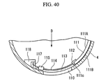
- FIG. 40 is a sectional view taken along the direction perpendicular to the longitudinal direction of the lateral hole.
- FIG. 42 is a sectional view of FIG. 40 , in which a slider cover is closed.
- FIG. 46 is a sectional view showing another example of a mechanism that opens and closes the slider cover.
- FIG. 47 is a sectional view of an entanglement preventing portion that is formed of an elastic member.
- FIG. 48 is a diagram showing an overtube.
- FIG. 49 is a diagram for explaining a procedure with the overtube shown in FIG. 48 .
- FIG. 50 is a diagram showing the state in which a perforation is punctured into a biological tissue in front of a lesion.
- FIG. 52 is a diagram showing the state in which the balloon is inflated to displace other internal organs.
- FIG. 53 is a diagram showing the state in which a lesion is drawn in while the balloon is inflated.
- FIG. 54 is a perspective view of a distal end portion of a basket-type forceps in a closed state.
- FIG. 55 is a perspective view of the distal end portion of the basket-type forceps in an unfolded state.
- FIG. 56 is a perspective view of a distal end portion of the entanglement preventing portion in a closed state.
- FIG. 57 is a perspective view of the entanglement preventing portion in an unfolded state.
- FIG. 60 is a diagram showing the state in which the overtube is inserted so as to approach a treatment target portion.
- FIG. 61 is a diagram showing the state in which the treatment target portion is drawn into a chamber.
- FIG. 63 is a view taken from the direction of the arrow F in FIG. 62 .
- FIG. 64 is a view taken from the direction of the arrow G in FIG. 63 .
- FIG. 65 is a diagram showing the structure of the grasping unit, showing the state in which a second jaw is closed.
- FIG. 66 is a view taken from the direction of the arrow H in FIG. 65 .
- FIG. 68 is a side-sectional view showing the structure of the suture unit.
- FIG. 72 is a diagram showing the state in which a knot is extruded by a knot pusher.
- FIG. 73 is a diagram showing a biological tissue that is sutured by a suturing tool.
- FIG. 75 is a view taken from the direction of the arrow J in FIG. 74 , showing a first pre-jet and a holding portion.
- FIG. 76 is a diagram showing a treatment target portion that is sutured by the suturing tool.
- FIG. 79 is a diagram showing the treatment target portion that is sutured by the suturing tool.
- FIG. 81 is a diagram showing the state in which the slider cover is open after the suture treatment is performed.
- FIG. 82 is a diagram showing the structure of a bi-parting grasping unit.
- FIG. 83 is a side-sectional view of a suture unit including the grasping unit shown in FIG. 82 .
- an endoscopic treatment system 1 includes an elongated overtube 2 serving as a pressing member main body that is inserted into the body of a patient.
- the overtube 2 is provided with a chamber 4 at a distal end of a flexible tube main body 3 .
- the chamber 4 extends in a cylindrical shape while the diameter thereof is enlarged from the distal end portion of the tube main body 3 .
- a flexible insertion guide 5 is provided on the distal end surface of the chamber 4 .
- the insertion guide 5 is a cylindrical member that is located at a position axially offset with respect to the chamber 4 .
- a transitional portion where the distal end portion of the chamber 4 transitions into the insertion guide 5 is formed as a tapered portion 6 that is cut obliquely toward the insertion guide 5 .
- a lateral hole 10 is formed parallel to the longitudinal direction in a long and thin shape.
- the chamber 4 of the overtube 2 functions as an entanglement preventing portion that includes a first surface 4 a that is opposed to an endoscope 7 side, a second surface 4 b that is opposed to a treatment target portion (a lesion W 1 ), and a pressing portion 4 c provided on a portion that connects the first surface 4 a and the second surface 4 b to each other.
- an endoscope 7 and an endoscopic suturing device (hereinafter referred to as a suturing device) 8 are inserted from a proximal end side thereof.
- the endoscope 7 includes an operation portion 11 that an operator operates with.
- an elongated flexible insertion portion 12 is provided.
- the distal end portion of the insertion portion 12 is inserted into the chamber 4 .
- an image capturing portion 13 that captures an image of the internal body and a distal opening of a treatment tool channel 14 are provided.
- the treatment tool channel 14 passes through the endoscope 7 into the operation portion 11 .
- an endoscopic treatment tool such as a grasping forceps 15 can be inserted, or operations such as suction or liquid delivery can be performed.
- the suturing device 8 includes a first operation portion 16 and a second operation portion 17 that an operator operates with.
- the first operation portion 16 is configured such that a hollow piston 19 is inserted into an operation portion main body 18 so as to be freely moved forward or backward.
- a hollow slider 20 is inserted so as to be freely moved forward or backward with respect to the piston 19 .
- a proximal end portion of a first insertion portion 21 that is flexible and elongated is attached.
- the first insertion portion 21 is inserted through the inside of a sheath so that a hollow liquid supply tube connected to the piston 19 can be freely moved forward or backward.
- a pusher rod connected to the slider 20 is inserted so as to be freely moved forward or backward.
- the second operation portion 17 is configured such that a slider 26 is attached to an operation portion main body 25 so as to be freely moved forward or backward.
- a hole is formed on the proximal end of the operation portion main body 25 and on the slider 26 so that an operator can grasp the second operation portion 17 with his fingers hooked on the holes.
- a proximal end portion of a second insertion portion 27 that is flexible and elongated is attached.
- the second insertion portion 27 is inserted through the inside of a sheath so that an operation wire connected to the slider 26 can be freely moved forward or backward.
- a suture unit 30 is provided, as shown in FIG. 4 .
- the suture unit 30 includes a shaft portion 31 to which the sheaths of the first and second insertion portions 21 and 27 (see FIG. 1 ) are connected.
- a first jaw 32 serving as a first grasping piece is provided at the distal end of the shaft portion 31 .
- the first jaw 32 has a proximal end portion thereof located at a position offset from the central axis of the shaft portion 31 , and a main body portion 33 that extends in the insertion direction from the proximal end portion, i.e., in the direction for being inserted into the body.
- a tooth 34 serving as a first convex portion is provided so as to extend in a direction perpendicular to the longitudinal direction of the main body portion 33 over the central axis of the shaft portion 31 .
- a plurality of teeth 35 serving as a second convex portion is arranged at regular intervals.
- the teeth 35 have the same shape as that of the tooth 34 , so that the first jaw 32 has a comb-teeth shape as a whole.
- a vertex portion 34 a (a first vertex portion) of the tooth 34 and vertex portions 35 a (a second vertex portion) of the teeth 35 are formed of a flat surface that is parallel in the longitudinal direction.
- through-holes 36 are formed in the teeth 34 and 35 so as to penetrate through the teeth 34 and 35 in a direction parallel to the longitudinal direction of the first jaw 32 .
- slits 37 that are open to the vertex portions 34 a and 35 a of the teeth 34 and 35 are formed so as to be connected to the through-holes 36 .
- an operation wire 28 is wound so as to be freely moved forward or backward.
- the operation wire 28 passes through the inside of the second insertion portion 27 shown in FIG. 1 and is connected to the slider 26 of the second operation portion 17 .
- a link mechanism 38 is attached on the distal end portion of the operation wire 28 .
- the link mechanism 38 is provided with an L-shaped lever 40 that is supported on the shaft portion 31 by a pin 39 so as to pivot in response to the forward and backward movement of the operation wire 28 .
- the lever 40 is attached so as to pivot about a position located on the opposite side in the offset direction of the first jaw 32 .
- a proximal end portion of a second jaw 42 serving as a second grasping piece is attached on the distal end of the lever 40 .
- the second jaw 42 has an elongated main body portion 43 .
- a plurality of teeth 44 serving as a third convex portion is arranged at regular intervals so as to extend in a direction perpendicular to the longitudinal direction.
- the second jaw 42 has a comb-teeth shape as a whole.
- the teeth 44 of the second jaw 42 and the teeth 34 and 35 of the first jaw 32 are arranged in an alternating manner.
- the vertex portions 44 a (third vertex portion) of the teeth 44 are formed of a flat surface.
- each of the teeth 44 has a through-hole 46 and a slit 47 .
- a grasping unit formed by the first and second jaws 32 and 42 is opened as shown in FIG. 5 when the operation wire 28 is moved forward, and as shown in FIG. 7 , the grasping unit is closed when the operation wire 28 is moved backward.
- the teeth 34 , 35 , and 44 are sequentially arranged in the longitudinal direction so that the through-holes 36 and 46 are linearly aligned.
- gaps that have a crank shape with a predetermined width are defined.
- the length La between the proximal end portion and the distal end portion of the first and second jaws 32 and 42 is set greater than the longitudinal length Lb of the lateral hole 10 .
- the wall surfaces in the longitudinal direction of the lateral hole 10 function as tissue restricting portions 48 . The operations of the tissue restricting portions 48 will be described later.
- a through-hole 50 is formed in the shaft portion 31 along the longitudinal direction thereof.
- a tissue penetrating needle 51 is inserted into the through-hole 50 .
- the tissue penetrating needle 51 includes a needle portion 53 that is attached to the distal end of the liquid supply tube 52 of the first insertion portion 21 .
- the needle portion 53 is formed of a hollow member having a sharply cut distal end, and the pusher rod 54 is inserted through the needle portion 53 and the liquid supply tube 52 so as to be freely moved forward or backward. Therefore, when the piston 19 of the first operation portion 16 shown in FIG. 1 is moved forward or backward, the liquid supply tube 52 and the needle portion 53 are moved forward or backward. When the slider 20 is moved forward or backward with respect to the piston 19 , the pusher rod 54 is moved forward or backward into the liquid supply tube 52 and the needle portion 53 .
- the outer diameter of the needle portion 53 and the liquid supply tube 52 is set smaller than the outer diameter of the through-holes 36 and 46 .
- the suturing tool 60 has the T bar 61 formed of a long and thin member.
- the T bar 61 has a thickness that can be pressed against the distal end of the pusher rod 54 .
- a suture thread 62 serving as a suture member is extended.
- the suture thread 62 is passed through a slit 63 formed on the lateral portion of the needle portion 53 and is again passed through a hole 64 formed on the lateral portion of the shaft portion 31 , finally being drawn out from the suture unit 30 .
- a stopper 65 serving as a fixing member is press-fitted so as to be freely moved forward or backward.
- the treatment target portion is not limited to this.
- the endoscope 7 is inserted through the overtube 2 , and the distal end portion of the insertion portion 12 is protruded out from the distal end of the insertion guide 5 .
- the overtube 2 is inserted into the body through the insertion guide 5 . Since the insertion guide 5 is more flexible and smaller in diameter than the chamber 4 , the overtube 2 can be inserted into the body in a smooth manner.
- the lesion W 1 is a treatment target portion that is to be resected entirely.
- the insertion portion 12 of the endoscope 7 is moved backward to confirm whether the lateral hole 10 is properly aligned with the lesion W 1 by using the image pickup portion 13 of the endoscope 7 . Then, the grasping forceps 15 (see FIG. 4 ) inserted through the treatment tool channel 14 is extended so as to allow the distal end to come out from the chamber 4 through the lateral hole 10 , thereby grasping the lesion W 1 . Once the lesion W 1 is grasped, the grasping forceps 15 is moved backward.
- the lesion W 1 is drawn into the chamber 4 through the lateral hole 10 by being pulled by the grasping forceps 15 .
- the width of the lateral hole 10 is set small, and thus the width of the biological tissue that is drawn into the chamber 4 is restricted by the width of the lateral hole 10 . Therefore, the lesion W 1 and two biological tissues ⁇ and ⁇ on the outer circumference of the lesion W 1 are drawn into the chamber 4 with the two biological tissues ⁇ and ⁇ overlapping with each other.
- other neighboring tissues or other neighboring biological tissues other than the treatment target portion, such as other internal organs W 3 are pressed against the peripheral border of the lateral hole 10 and thus are not drawn into the chamber 4 .
- the biological tissues ⁇ and ⁇ are the treatment target portion that is to be sutured.
- a suture treatment is performed on the biological tissues ⁇ and ⁇ with the suturing device 8 .
- the suture unit 30 is moved forward toward the lesion W 1 in the state in which the first jaw 32 is opened with respect to the second jaw 42 .
- the length between the tissue restricting portions 48 i.e., the longitudinal length Lb of the lateral hole 10 is smaller than the longitudinal length La of each of the jaws 32 and 42 . Therefore, as shown in FIG. 15 , the length of the biological tissues ⁇ and ⁇ is restricted by the tissue restricting portions 48 of the lateral hole 10 so as to be smaller than that of the jaws 32 and 42 . As a result, the biological tissues ⁇ and ⁇ do not stick out from the distal or proximal end portion of the jaws 32 and 42 .
- the second jaw 42 is closed to sandwich the biological tissues ⁇ and ⁇ between the first and second jaws 32 and 42 as shown in FIG. 16 without the biological tissues ⁇ and ⁇ sticking out from the jaws.
- the biological tissues ⁇ and ⁇ assume the shape of the crank-shaped gap between the first and second jaws 32 and 42 and are sandwiched between the corrugated surfaces, more specifically between the rectangular corrugated surfaces assuming the outer shapes of the teeth 34 , 35 , and 44 .
- the piston 19 of the first operation portion 16 shown in FIG. 1 is operated to move the tissue penetration needle 51 in the forward direction.
- the tissue penetration needle 51 penetrates the biological tissues ⁇ and ⁇ sandwiched between the teeth 34 , 35 , and 44 with the needle portion 53 pierced into the biological tissues ⁇ and ⁇ , and is sequentially passed through the through-holes 36 and 46 of the teeth 34 , 35 , and 44 , finally coming out from the distal end.
- the T bar 61 received in the needle portion 53 also comes out through the biological tissues ⁇ and ⁇ , and therefore the suture thread 62 attached to the T bar 61 is passed through the biological tissues ⁇ and ⁇ and the first and second jaws 32 and 42 .
- the slider 20 of the first operation portion 16 is operated to move the pusher rod 54 in the forward direction, as shown in FIGS. 17 and 18 , the T bar 61 is extruded from the needle portion 53 .
- the piston 19 is operated to move the needle portion 53 in the backward direction. With this operation, the needle portion 53 is removed from the biological tissues ⁇ and ⁇ . However, because the T bar 61 extruded from the needle portion 53 is detained at a more distal side than the first and second jaws 32 and 42 , the suture thread 62 maintains the state in which the suture thread 62 is passed through the biological tissues ⁇ and ⁇ .
- the suture thread 62 passes through the slits 37 and 47 and comes out from the first and second jaws 32 and 42 , and the suturing tool 60 comes off the suture unit 30 .
- the suture thread 62 is passed through an approximately central portion of the corrugated biological tissues ⁇ and ⁇
- the T bar 61 is disposed at the distal end side of the biological tissues ⁇ and ⁇
- the stopper 65 is disposed at the proximal end side of the biological tissues ⁇ and ⁇ .
- the ligating tool 70 is configured such that a wire 72 is inserted through an elongated sheath 71 so as to be freely moved forward and backward. At the distal end of the wire 72 , a hook 73 serving as an engagement member is fixedly attached. Such a ligating tool 70 is used by being inserted through the treatment tool channel 14 of the endoscope 7 . As shown in FIG. 23 , the hook 73 as shown in FIG. 24 is moved closer to a proximal side loop 66 of the suture thread 62 passed through the biological tissues ⁇ and ⁇ . Once the hook 73 is hooked on the loop 66 , an operator-side operation portion is operated to draw the hook 73 into the sheath 71 .
- the loop 66 engaged on the hook 73 is drawn into the sheath 71 .
- the stopper 65 abuts the distal end surface of the sheath 71 and stops there because the size of the stopper 65 is greater than the outer diameter of the sheath 71 .
- the stopper 65 is relatively extruded toward the biological tissues ⁇ and ⁇ , decreasing the distance between the T bar 61 and the stopper 65 .
- the treatment target portion is fastened by the T bar 61 and the stopper 65 in such a manner that the walls of the corrugated biological tissues ⁇ and ⁇ are brought into close contact with each other in an overlapping manner.
- the T bar 61 has a size that does not pass through the biological tissues ⁇ and ⁇ , and the stopper 65 is press-fitted to the suture thread 62 . Therefore, the fastening state of the biological tissues ⁇ and ⁇ is maintained when the force for drawing in the suture thread 62 is released. Accordingly, even after the engagement between the hook 73 and the suture thread 62 is released, the suture thread 62 , the T bar 61 , and the stopper 65 are detained in the body in the state in which the biological tissues ⁇ and ⁇ are securely sutured. In this way, as shown in FIG. 26 , the biological tissues ⁇ and ⁇ are fastened by the suturing tool 60 , and the surrounding portion of the lesion W 1 is sutured. In addition, because the T bar 61 and the stopper 65 abut the pouch-shaped outer peripheral surfaces of the biological tissues ⁇ and ⁇ , the biological tissues ⁇ and ⁇ can be securely sutured without leaving out any portion of the biological tissues ⁇ and ⁇ .
- a loop 81 of a high-frequency snare 80 is hooked on a portion closer to the lesion W 1 than the sutured portion. Since the high-frequency snare 80 is used by being inserted into the treatment tool channel 14 of the endoscope 7 , the loop 81 is formed of metal such as stainless steel and is adapted to freely come into and out of the elongated sheath 82 .
- the loop 81 By operating the operator-side operation portion, the loop 81 can be drawn into the sheath 82 . In the state in which the surrounding portion of the lesion W 1 is fastened, a high-frequency current is supplied to the loop 81 , resecting the lesion W 1 . The resected lesion W 1 is collected outside the body by the grasping forceps 15 or the like. As shown in FIG. 28 , the biological tissues ⁇ and ⁇ 3 remaining after the entire lesion W 1 is resected are left in the state that the biological tissues ⁇ and ⁇ are sutured by the suturing tool 60 .
- the treatment target portion when resecting the entire lesion W 1 , the treatment target portion can be drawn into the chamber 4 in the state in which tissues around the treatment target portion are pressed against the chamber 4 .
- the entanglement preventing portion is configured as the lateral hole 10 of the chamber 4 that has a small width corresponding to the size of the lesion W 1 . Therefore, only the minimal biological tissue required for the procedure can be drawn into the chamber 4 . Thus, other biological tissues, particularly other organs W 3 on the periphery of the intestinal tract W are not drawn into the chamber 4 . Therefore, during the procedure, it is not necessary to confirm whether other organs W 3 or the like are drawn into the chamber 4 , simplifying the procedure and raising the efficiency of the procedure.
- the chamber 4 is provided with the flexible and thin insertion guide 5 at its distal end, and the insertion guide 5 deforms so as to assume the shape of the insertion portion 12 of the endoscope 7 or of the internal body. Therefore, the overtube 2 can be easily inserted to an intended site. Since the tapered portion 6 is provided at the distal end of the chamber 4 , even when the intestinal tract W is curved, the tapered portion 6 deforms while colliding against the tract wall to change the moving direction of the chamber 4 so as to assume the curved shape of the intestinal tract W. Accordingly, it is possible to insert the overtube 2 in an easier manner.
- the suturing device 8 includes the grasping unit formed by the comb-teeth shaped, first and second jaws 32 and 42 .
- the suture thread 62 is passed through the biological tissues ⁇ and ⁇ using the tissue penetration needle 51 , and then the biological tissues ⁇ and ⁇ are sutured while being sandwiched between the T bar 61 and the stopper 65 . Therefore, the biological tissues ⁇ and ⁇ are joined with each other. Accordingly, perforations formed after the lesion W 1 is resected are securely blocked, and the biological tissues ⁇ and ⁇ are immediately coalesced, thereby obstructing the perforations.
- the vertex portions 34 a , 35 a , and 44 a of the teeth 34 , 35 , and 44 of the first and second jaws 32 and 42 are formed of a flat surface, the biological tissues ⁇ and ⁇ sandwiched in a corrugated shape can be folded at an angle close to a right angle. Therefore, when fastened by the suture thread 62 , the shape of the biological tissues ⁇ and ⁇ is not likely to change. In this way, in the present embodiment, operations up to the ligating operation can be performed in a trans-endoscopic manner.
- the drawn-in length of the treatment target portion in the longitudinal direction of the jaws 32 and 42 is restricted by the tissue restricting portion 48 .
- the portion to be sutured does not stick out from the distal or proximal end portion of the jaws 32 and 42 . Therefore, the end portions of the biological tissues ⁇ and ⁇ are securely sutured without leaving out any portion of the biological tissues ⁇ and ⁇ .
- the overtube 2 functions as a tissue pressing member main body and a tissue restricting member.
- the length Lc of the T bar 61 is preferably the same as or greater than the length Ld of the teeth 34 , 35 , and 44 of the first and second jaws 32 and 42 . Since the T bar 61 is longer than the width of the overlapped, corrugated-shaped biological tissues ⁇ and ⁇ , the T bar 61 can press the entire width of the biological tissues ⁇ and ⁇ . Accordingly, the entire biological tissues ⁇ and ⁇ can be pressed in a secure manner.
- the snare 85 By adjusting the longitudinal position of the snare 85 by moving the snare 85 forward or backward in the longitudinal direction, it is possible to prevent the biological tissues ⁇ and ⁇ that need to be sutured from sticking out of the longitudinal ends of the jaws 32 and 42 . In this case, it is not necessary to form the tissue restricting portion 48 (see FIG. 8 ) in the lateral hole 10 a .
- the snare 85 may be inserted through the overtube 2 instead of inserting through the endoscope 7 .
- the tissue restricting member include a treatment tool such as a grasping forceps that can restrict the length of the biological tissues ⁇ and ⁇ .
- the endoscope 7 may be used as the tissue restricting member.
- the pressing member may have other shapes, for example, those shown in FIGS. 31 to 33 may be employed.
- the chamber 4 may have, as the entanglement preventing portion, a hole 90 that is long in the circumferential direction of the chamber 4 .
- the width of the lateral hole 90 in a direction perpendicular to the circumferential direction is approximately the same as the width of the lateral hole 10 shown in FIG. 2 .
- the wall surfaces of the lateral hole 90 in the longitudinal direction of the chamber 4 correspond to a pressing portion 4 d . Therefore, the treatment target portion can be drawn in a long and thin shape in a direction approximately perpendicular to the forward and backward movement directions of the grasping forceps 15 .
- the sutured portion extends in a direction approximately perpendicular to the movement direction of food or like that flows along the intestinal tract W.
- the sutured biological tissues are not likely to cause stenosis.
- a pressing member 91 attached at the distal end of the endoscope 7 may be used.
- the pressing member 91 has a pressing member main body 93 that is mounted on the distal end portion of the insertion portion 12 of the endoscope 7 by an annular engagement portion 92 .
- the pressing member main body 93 is formed of a plate-shaped member and protrudes out from the distal end of the endoscope 7 in a long and thin shape along the axial line of the insertion portion 12 .
- a lateral hole 94 serving as the entanglement preventing portion is formed in the longitudinal direction.
- the lateral hole 94 is penetrated through the pressing member main body 93 , and the length and the opening width are the same as those of the lateral hole 10 shown in FIG. 2 .
- the surface on the endoscope 7 side of the pressing member main body 93 corresponds to a first surface 93 a
- an opposite surface of the first surface 93 a corresponds to a second surface 93 b.
- the wall surfaces in a direction perpendicular to the longitudinal direction of the pressing member main body 93 correspond to a pressing portion 93 c .
- a pressing member 91 neighboring tissues of the treatment target portion are pressed against the pressing member main body 93 , and the entanglement of other organs W 3 or the like is prevented by the lateral hole 94 .
- the lateral hole 94 may be extended in a direction perpendicular to the longitudinal direction of the pressing member main body 93 .
- a pressing member 95 may have a pair of arms 96 that extends in a direction parallel to the longitudinal direction of the insertion portion 12 of the endoscope 7 .
- the arms 96 is a pressing member main body that is fixed to an annular engagement portion 92 .
- a space 97 serving as the entanglement preventing portion is defined between the pair of arms 96 .
- the width of the space 97 in a direction perpendicular to the longitudinal direction is substantially the same as the opening width of the lateral hole 10 shown in FIG. 2 .
- the plane connecting the end portions of the pair of arms 96 on the endoscope 7 side corresponds to the first surface
- the plane connecting the end portions located farthest from the endoscope 7 corresponds to the second surface.
- the portions opposed to the pair of arms 96 correspond to a pressing portion.
- a pressing member 95 neighboring tissues of the treatment target portion are pressed against the pair of arms 96 , and the entanglement of other organs W 3 or the like is prevented by the space 97 .
- the pressing member 91 or the pressing member 95 may be used as the tissue restricting member.
- FIGS. 34 to 39 A second embodiment will be described with reference to FIGS. 34 to 39 . Components similar or identical to those of the first embodiment will be referenced by the same reference numerals, and overlapping descriptions will be omitted.
- a lateral hole 100 is an entanglement preventing portion that includes an elongated, first opening 101 and a second opening 102 that is provided to be connected to the distal end side of the first opening 101 .
- the first opening 101 has the same length and width as that of the lateral hole 10 according to the first embodiment.
- the second opening 102 is formed in a substantially circular shape and has a width greater than that of the first opening 101 .
- the overtube 2 is inserted with the second opening 102 opposed to the lesion W 1 , the grasping forceps 15 is extended to grasp the lesion W 1 through the second opening 102 . Then, the grasping forceps 15 is slightly pulled backward so that the distal end is received into the chamber 4 . With this operation, the lesion W 1 is slightly drawn into the chamber 4 .
- the biological tissues ⁇ and ⁇ drawn from the first opening 101 are sutured in a corrugated shape. Therefore, as shown in FIG. 39 , when the whole overtube 2 is moved backward, the sutured biological tissues ⁇ and ⁇ are relatively moved backward toward the wide, second opening 102 . As a result, the biological tissues ⁇ and ⁇ and the suturing tool 60 come out of the chamber 4 through the second opening 102 .
- the entanglement preventing portion is formed by the first and second openings 101 and 102 having different opening widths, the lesion W 1 can be grasped through the second opening 102 in an easy manner.
- the suture treatment since the suture treatment is performed when the lesion W 1 is moved to the narrow, first opening 101 , the suture treatment can be performed without causing other organs W 3 or the like to be drawn in, and it is thus easy to confirm whether the entanglement of other organs W 3 or the like occurs.
- the sutured biological tissues ⁇ and ⁇ can be removed out of the chamber 4 through the wide, second opening 102 , it is possible to pull the sutured portion out from the chamber 4 immediately along with the T bar 61 or the stopper 65 that has a large size.
- the second opening 102 is first controlled to be opposed to the lesion W 1 , it is possible to widen the view field offered by the endoscope 7 , making it easier to identify the position of the lesion W 1 .
- FIGS. 40 to 47 A third embodiment will be described with reference to FIGS. 40 to 47 .
- Components similar or identical to those of the afore-described embodiments will be referenced by the same reference numerals, and overlapping descriptions will be omitted.
- a lateral hole 110 is formed in the chamber 4 .
- the width of the lateral hole 110 in the circumferential direction of the chamber 4 is sufficiently larger than the thickness of the total layers of the lesion W 1 to be drawn in.
- a slider cover 111 serving as the entanglement preventing portion is attached so as to be freely movable in the circumferential direction.
- the slider cover 111 includes a first surface 111 A which is the inner circumferential surface opposed to the endoscope 7 , and a second surface 111 B which is the outer circumferential surface opposed to the treatment target portion.
- the slider cover 111 has a size that can cover the entire lateral hole 110 from the inside.
- a pair of guides 112 is mounted on the end portions on the lateral hole 110 side of the slider cover 111 .
- the guides 112 are slidably fitted to a pair of rails 113 that are laid between the distal and proximal end sides of the lateral holes 110 in a direction parallel to the circumferential direction.
- the guides 112 are connected to wires 114 .
- Each of the wires 114 is drawn along the pair of rails 113 , then passed through a through-hole 116 of a wire guide 115 , and is turned in the longitudinal direction of the chamber 4 while assuming the shape of the outer circumference of a pin 117 .
- the pin 117 is fixed to the inner circumference of the chamber 4 . As shown in FIG. 40 , the distal end of the pin 117 is pressed against an L-shaped pressing member 118 , preventing the wire 114 from dropping out from the pin 117 .
- the end portions of the wire 114 are connected to the distal end portions of an operation wire 119 .
- the operation wire 119 is inserted through a sheath 120 fixed to the inner wall of the overtube 2 so as to be freely moved forward or backward.
- the sheath 120 is connected to an operation portion main body 122 of an operator-side operation portion 121 that is drawn out of the body.
- the proximal end portion of the operation wire 119 is fixed to a slider 123 that can be freely moved forward or backward with respect to the operation portion main body 122 .
- the slider cover 111 is moved with the operation wire 119 and the wire 114 so as to cover the lateral hole 110 , the shown in FIGS. 42 and 43 .
- an opening width that allows the passage of the biological tissue required for the entire resection for example, a gap of about 3 mm is defined by the lateral hole 110 and a pressing portion 111 C that is formed of the lateral surface of the slider cover 111 .
- a stopper (not shown) may be provided on the pair of rails 113 in order to provide the necessary opening width to the lateral hole 110 .
- the overtube 2 is inserted such that the lateral hole 110 is opposed to the lesion W 1 .
- the distal end of the grasping forceps 15 is pulled backward so as to be received into the chamber 4 .
- the operator-side operation portion 121 is operated to move the slider cover 111 to cover the lateral hole 110 while leaving a small gap.
- FIG. 45 when the grasping forceps 15 is pulled, neighboring tissues are pressed against the peripheral border of the lateral hole 110 and the second surface 111 B of the slider cover 111 .
- the treatment target portion is drawn into the chamber 4 with the width restricted by the lateral hole 110 and the pressing portion 111 C of the slider cover 111 , preventing other organs W 3 from being drawn into the chamber 4 .
- the biological tissues ⁇ and ⁇ are sutured by the suturing device 8 , and the entire lesion W 1 is resected by the high-frequency snare 80 .
- the operator-side operation portion 121 is operated to move the slider cover 111 to uncover the lateral hole 110 , and the sutured portion is removed out of the chamber 4 .
- the opening width is increased, making it easy to identify the position of the lesion W 1 and to insert the grasping forceps 15 .
- the slider cover 111 is moved to decrease the opening width.
- the width of the biological tissue to be drawn into the chamber 4 is restricted by the opening width defined by the pressing portion 111 C of the slider cover 111 . Therefore, by setting the opening width to a size that allows the passage of only the treatment target portion, it is possible to prevent entanglement of other organs W 3 or the like and to facilitate the procedure.
- FIGS. 46 and 47 can be exemplified.
- the other end of the slider cover 111 is attached to one end of a coil spring 130 .
- the other end of the coil spring 130 is fixedly attached to a protrusion 131 provided on the inner circumference of the chamber 4 .
- the slider cover 111 is biased by the coil spring 130 so as to cover the lateral hole 110 while leaving a gap.
- the lesion W 1 is drawn into the chamber 4 through the gap using the grasping forceps 15 .
- the slider cover 111 is moved toward the protrusion 131 while resisting the force that moves the slider cover 111 toward the lesion W 1 .
- the treatment target portion is drawn into the chamber 4 with the drawn-in width corresponding to the increased opening width defined by the lateral hole 110 and the pressing portion 111 C. Since the slider cover 111 is biased by the coil spring 130 , the opening width is not unnecessarily increased, and thus other organs W 3 or the like are not drawn into the chamber 4 through such a small opening width. Accordingly, other neighboring tissues other than the treatment target portion are pressed, preventing the entanglement of other organs W 3 .
- valve elements 140 and 141 serving as first and second entanglement preventing portions, respectively, made of an elastic member such as rubber are attached to the lateral hole 110 such that the opening width is decreased from the circumferential direction.
- the lateral portions of the valve elements 140 and 141 are fixed to the lateral borders of the lateral hole 110 by means of adhesive bonding or the like.
- the valve elements 140 and 141 are deformed about the lateral portions so as to be bent toward the inside, forming an elongated space that extends in the longitudinal direction between opposite ends 140 A and 141 A of the pair of valve elements 140 and 141 .
- opposite ends 140 A and 141 A correspond to the pressing portion.
- the circumferential width of the space defined by the opposite ends 140 A and 141 A is substantially the same as the width of the lateral hole 10 shown in FIG. 2 .
- the opening width is not unnecessarily increased, and thus other organs W 3 or the like are not drawn into the chamber 4 through such a small opening width. Accordingly, other neighboring tissues other than the treatment target portion are pressed, preventing the entanglement of other organs W 3 .
- FIGS. 48 to 57 A fourth embodiment will be described with reference to FIGS. 48 to 57 . Components similar or identical to those of the afore-described embodiments will be referenced by the same reference numerals, and overlapping descriptions will be omitted.
- the lateral hole 110 (a first opening) is formed in the chamber 4 , and a slider cover 150 that can cover the lateral hole 110 is attached to the outer circumference of the chamber 4 so as to be freely moved forward or backward.
- the slider cover 150 is connected to the same mechanism as the slider cover 111 of the third embodiment and to an operator-side operation portion 121 .
- an opening (a second opening) 151 smaller than the lateral hole 110 is provided on a portion of the chamber 4 closer to the distal end than the formation position of the lateral hole 110 .
- the opening 151 has a size that allows the passage of the distal end portion of the grasping forceps 15 but does not allow the drawing in of the entire lesion W 1 .
- two grasping forceps 15 are inserted through a channel separately from that of the endoscope 7 and the suturing device 8 .
- the grasping forceps 15 is inserted through respective sheaths 152 and 153 that are fixed to the wall of the overtube 2 one by one.
- the sheath 152 has a distal opening that is tilted to be opposed to the opening 151 .
- the sheath 153 has a distal opening that is tilted to be opposed to the lateral hole 110 .
- the overtube 2 is inserted into the body.
- the reason the lateral hole 110 is covered is that by doing this, the insertion can be done in a smooth manner without being caught halfway.
- the endoscope 7 is pulled backward closer to the outside than the formation position of the opening 151 , and the grasping forceps 15 inserted through the sheath 152 is extended so as to be inserted into the opening 151 .
- a biological tissue at a small distance from the lesion W 1 is grasped and is drawn into the chamber 4 through the opening 151 .
- a small perforation is formed in the biological tissue drawn into the chamber 4 using a high-frequency arm 154 inserted through the endoscope 7 . Since the opening 151 has a small area, other organs W 3 are not drawn into the chamber 4 through such a small opening.
- a balloon catheter 155 serving as an entanglement preventing portion is inserted through the endoscope 7 , and a balloon 156 serving as a displacing member provided at the distal end portion is delivered to the outside of the intestinal tract W through the perforation formed on the biological tissue.
- the position of the balloon 156 can be observed through X-ray irradiation, for example.
- the slider cover 150 is moved to uncover the later hole 110 , and air is blown into the balloon catheter 155 to expand the balloon 156 .
- the small opening 151 for inserting the balloon catheter 155 is provided on the operator side of the lateral hole 110 through which the lesion W 1 is drawn in, and the balloon 156 is expanded after being inserted through the opening 151 . It is possible to physically separate other organs W 3 from the intestinal tract W and to thus prevent the entanglement of other organs W 3 in a secure manner. Since other organs W 3 can be securely separated, the lateral hole 110 can have a greater size and it is thus possible to draw in a larger amount of the treatment target portion.
- a basket-type forceps 160 as shown in FIGS. 54 and 55 can be used.
- the basket-type forceps 160 is configured such that an operation wire 162 is inserted through a long and flexible sheath 161 so as to be freely moved forward or backward.
- a basket 163 (a displacing member) formed of an elastically deformable wire is provided.
- the basket-type forceps 160 is inserted through the endoscope 7 and is then passed by the intestinal tract W, finally being delivered to a position opposite the lateral hole 110 with the lesion W 1 interposed therebetween.
- the operation wire 162 is moved forward to unfold the basket 163 , separating other organs W 3 from the intestinal tract W.
- an entanglement preventing portion 165 as shown in FIGS. 56 and 57 may be used.
- the entanglement preventing portion 165 is configured such that a plurality of displacing members 168 is attached to the distal end of a long and flexible insertion portion 166 so that the displacing members 168 can freely pivot about a pin 167 .
- Each of the displacing members 168 is formed of a plate-shaped member, and one longitudinal end thereof is supported on the pin 167 .
- the entanglement preventing portion 165 is inserted through the endoscope 7 and is then passed by the intestinal tract W, finally being delivered to a position opposite the lateral hole 110 with the lesion W 1 interposed therebetween.
- the displacing members 168 are unfolded in a fan-like shape while being pivoted about the pin 167 . With this, the entanglement of other organs W 3 is prevented.
- a mechanism can be contemplated which biases the displacing members 168 to be unfolded in a normal state and folds the displacing members 168 when pulled by an operation wire (not shown).
- a fifth embodiment will be described with reference to FIGS. 58 to 61 .
- Components similar or identical to those of the afore-described embodiments will be referenced by the same reference numerals, and overlapping descriptions will be omitted.
- the overtube 2 is provided with the chamber 4 at a distal end portion of the long and flexible tube main body 3 .
- the small-diameter, flexible insertion guide 5 is provided on the distal end surface of the chamber 4 .
- the chamber 4 has a higher hardness than the tube main body 3 and the insertion guide 5 .
- a lateral hole 170 serving as an opening is formed in the tapered portion 6 that extends from the distal end surface while enlarging the diameter of the chamber 4 .
- the insertion guide 5 can be deformed along with the insertion portion 12 of the endoscope 7 while assuming the shape of the alimentary tract W 4 . Accordingly, it is easy to allow the overtube 2 to follow the way the endoscope 7 moves.
- the lesion W 1 is drawn into the lateral hole 170 . Since the lateral hole 170 is tilted with respect to the insertion direction, the endoscope 7 can directly approach the lesion W 1 . Therefore, as shown in FIG. 61 , the lesion W 1 can be grasped by the grasping forceps 15 almost without bending the grasping forceps 15 and can be drawn into the chamber 4 . In the present embodiment, since the lateral hole 170 is provided in the tapered portion 6 , it is possible to observe the lesion W 1 without bending the distal end portion of the endoscope 7 and to thus facilitate the procedure. Also, the grasping forceps 15 can be operated in a simple manner.
- FIGS. 62 to 67 A sixth embodiment will be described with reference to FIGS. 62 to 67 . Components similar or identical to those of the afore-described embodiments will be referenced by the same reference numerals, and overlapping descriptions will be omitted.
- a suture unit 180 of the suturing device 8 includes, as a grasping unit, the first jaw 32 and the second jaw 42 that is freely slidable toward or away from the first jaw 32 .
- the second jaw 42 has a comb-teeth shape in which teeth 44 are arranged at regular intervals on the main body portion 43 .
- Slide portions 181 are provided at the proximal and distal ends of the second jaw 42 .
- Through-holes are formed in the slide portions 181 in a direction parallel to each of the teeth 44 , and the pair of rails 182 are inserted through respective through-holes one by one.
- the rails 182 are parallel to each other, and respective ends of the pair of rails 182 are held at holding portions 183 provided at the proximal and distal ends of the first jaw 32 .
- wires 184 are connected at positions closer to the longitudinal center of the second jaw 42 than the pair of rails 182 .
- the wires 184 are passed through the holding portions 183 of the first jaw 32 and are then drawn in the forward and backward movement directions while assuming the shape of the outer circumference of a pin 185 fixed to the inner wall of the chamber 4 .
- the wires 184 are incorporated into a single wire at a connection pipe 186 , and the single wire is connected to an operation wire 187 .
- the operation wire 187 is passed through a sheath 188 fixed to the inner wall of the overtube 2 and is connected to a slider 190 of an operator-side operation portion 189 outside the body.
- the pair of rails 182 are fixed to the inner wall of the chamber 4 .
- the slide portions 181 are connected to the inner wall of the chamber 4 via an elastic member 191 such as a coil spring. Under unloaded conditions, the second jaw 42 is biased in a direction for moving the second jaw 42 away from the first jaw 32 .
- the suture unit 180 in the initial state, is open and positioned over the lateral hole 10 .
- the operation wire 187 is pulled, causing the wires 184 to pull the second jaw 42 so as to be moved toward the first jaw 32 .
- the second jaw 42 is slid to a position where the second jaw 42 engages with the first jaw 32 while resisting the force of the elastic member 191 .
- the biological tissues ⁇ and ⁇ are sandwiched between the first and second jaws 32 and 42 in a corrugated shape. Then, the biological tissues ⁇ and ⁇ are sutured in a corrugated manner using the tissue penetrating needle 51 .
- the tissue penetrating needle 51 is removed from the biological tissues ⁇ and ⁇ , and the operator's hand is released from the handle 190 . Then, the second jaw 42 is pulled by the restoring force of the elastic member 191 , thereby opening the first and second jaws 32 and 42 .
- a ratchet-type operator-side operation portion 192 as shown in FIG. 67 may enable maintenance of the closed state or the predetermined degree of opening of the first and second jaws 32 and 42 .
- the operator-side operation portion 192 includes ratchet teeth arranged in the longitudinal direction on an operation portion main body 193 .
- a claw that engages with ratchet teeth 194 is formed in a handle 195 . The engagement between the ratchet teeth 194 and the claw is released by a button 196 on the handle 195 .
- the grasping unit includes the first and second jaws 32 and 42 that are opened and closed in a sliding manner.
- the grasping unit can be opened or closed while maintaining the same width from the proximal end side to the distal end side.
- a closing (grasping) force substantially of the same strength can be applied to the distal and proximal end sides. Since the first and second jaws 32 and 42 are attached to the inner wall of the chamber 4 , it is possible to place the jaws so as to be opposed to the lateral hole 10 and to thus stabilize the operations.
- a seventh embodiment will be described with reference to FIGS. 68 to 73 .
- Components similar or identical to those of the afore-described embodiments will be referenced by the same reference numerals, and overlapping descriptions will be omitted.
- a suture unit 200 of the suturing device 8 includes, as a grasping unit, the first jaw 32 and the second jaw 42 that can be freely opened or closed with respect to the first jaw 32 .
- the tissue penetrating needle 51 is inserted through the shaft portion 31 of the first jaw 32 so as to be freely movable forward or backward.
- the suture thread 62 is loosely bound to the exposed portion of the needle portion 53 , forming a knot 201 .
- One end of the suture thread 62 is drawn outside the body.
- the other end of the suture thread 62 is drawn to the distal end sides of the first and second jaws 32 and 42 while bypassing the first and second jaws 32 and 42 .
- a loop 202 provided at the distal end of the suture thread 62 is hooked on a hook portion 203 (see FIG. 68 ) that protrudes from the inner wall of the chamber 4 .
- a hook 204 (see FIG. 70 ) is provided within the tissue penetrating needle 51 so as to be freely moved forward or backward.
- the hook 204 is connected to the slider 20 of the first operation portion 16 shown in FIG. 1 .
- a knot pusher 205 capable of pressing the knot 201 is provided so as to be freely moved toward or backward.
- the biological tissues ⁇ and ⁇ on the outer circumference of the lesion W 1 are sutured.
- the second jaw 42 is moved to sandwich the biological tissues ⁇ and ⁇ in a corrugated shape between the first and second jaws 32 and 42 .
- the tissue penetrating needle 51 is moved forward to be sequentially penetrated through the teeth 34 , 35 , and 44 and the biological tissues ⁇ and ⁇ .
- the first operation portion 16 is operated to allow the hook 204 to protrude out from the distal end of the needle portion 53 so that the hook 204 is hooked on the loop 202 at the distal end of the suture thread 62 that is hooked on the hook portion 203 .
- the loop 202 is unhooked from the hook portion 203 and is received in the needle portion 53 .
- the first operation portion 16 is operated to move the tissue penetrating needle 51 in the backward direction.
- the suture thread 62 is drawn into the through-hole 36 of the distal tooth 34 and is then sequentially passed through the teeth 34 , 35 , 44 and the biological tissues ⁇ and ⁇ from the distal end side.
- the suture thread 62 is passed through the biological tissues ⁇ and ⁇ .
- the knot pusher 205 When the knot pusher 205 is moved forward, as shown in FIG. 72 , the knot 201 is extruded closer to the distal end side than the needle portion 53 . As a result, the suture thread 62 having passed through the biological tissues ⁇ and ⁇ is passed through the knot 201 and is drawn out to the operator side.
- the biological tissues ⁇ and ⁇ through which the suture thread 62 has been passed in a corrugated manner remain between the first and second jaws 32 and 42 .
- the end of the suture thread 62 connected from the knot 201 and the end of the suture thread 62 drawn out after passing through the knot 201 are pulled by the backward movement of the suture unit 200 .
- the biological tissues ⁇ and ⁇ are overlapped with each other in a corrugated shape, and the knot 201 is fastened.
- the remaining portion of the suture thread 62 is cut by scissor forceps or the like that is inserted through the endoscope 7 .
- the suturing tool is composed only of the suture thread 62 , it is possible to minimize the number of elements detained in the body. Since the suture treatment can be performed such that the biological tissues ⁇ and ⁇ are fastened after the end of the suture thread 62 is passed through the knot 201 , it is possible to simplify the procedure.
- FIGS. 74 to 76 An eighth embodiment will be described with reference to FIGS. 74 to 76 . Components similar or identical to those of the first embodiment will be referenced by the same reference numerals, and overlapping descriptions will be omitted.
- the suturing device 8 includes a suture unit 210 .
- a first pre-jet 211 used as a retaining patch is held at a holding portion 212 .
- the first pre-jet 211 is a thin, rectangular member having chamfered corners.
- the holding portion 212 protrudes from the inner wall of the chamber 4 and has a substantially U shape that is open toward the inside of the chamber 4 , forming a slit so that the peripheral border of the first pre-jet 211 is sandwiched between both ends of the U shape.
- the first pre-jet 211 constitutes a suturing tool 213 .
- the suturing tool 213 also includes the T bar 61 , the suture thread 62 , a second pre-jet 214 , and the stopper 65 .
- the second pre-jet 214 is provided at the distal end side of the stopper 65 , and the suture thread 62 is passed through an approximately central portion of the second pre-jet 214 .
- the second pre-jet 214 is substantially of the same shape and formed of the same material as the first pre-jet 211 .
- the first operation portion 16 When suturing the biological tissues ⁇ and ⁇ , in the state in which the biological tissues ⁇ and ⁇ are sandwiched between the first and second jaws 32 and 42 (only the first jaw 32 is shown in FIG. 74 ), the first operation portion 16 is operated to move the tissue penetrating needle 51 in the forward direction.
- the tissue penetrating needle 51 is sequentially passed through the teeth 34 , 35 , and 44 , the biological tissues ⁇ and ⁇ , and the approximately central portion of the first pre-jet 211 from the operator side.
- the pusher rod 54 is moved forward to extrude the T bar 61 to a more distal side than the first pre-jet 211 .
- the tissue penetrating needle 51 is moved backward to remove the needle portion 53 .
- the second jaw 42 is moved so as to separate the suture unit 210 from the biological tissues ⁇ and ⁇ , the suture thread 62 remains after being passed through the biological tissues ⁇ and ⁇ in a corrugated manner.
- the holding portion 212 of the first pre-jet 211 holds only the peripheral border of the first pre-jet 211 . Therefore, when the stopper 65 is moved forward to pull the suture thread 62 , the first pre-jet 211 is pulled out from the holding portion 212 by being pulled by the T bar 61 .
- the T bar 61 is pressed toward the distal end of the biological tissues ⁇ and ⁇ with the first pre-jet 211 interposed therebetween.
- the stopper 65 is pressed toward the proximal end of the biological tissues ⁇ and ⁇ with the second pre-jet 214 interposed therebetween. Accordingly, the biological tissues ⁇ and ⁇ are sutured.
- the procedure of the drawing-in and entire resection of the lesion W 1 is similar to that of the first embodiment.
- the suturing tool 213 since the suturing tool 213 includes the first and second pre-jets 211 and 214 , the T bar 61 or the stopper 65 does not make direct contact with the biological tissues ⁇ and ⁇ . Therefore, it is possible to prevent a load from being concentrated on a partial area of the biological tissues ⁇ and ⁇ .
- Other advantages of the present embodiment are the same as the afore-described embodiments.
- a suturing tool 220 as shown in FIG. 77 may be employed.
- the T bar 61 is attached to the distal end of a suture thread 62 , the suture thread 62 is passed through a fixing member 211 , and a loop 66 is formed at the proximal end of the suture thread 62 .
- the fixing member 221 is formed of a long and thin plate having a hole 222 at the center, through which the suture thread 62 is inserted. Both end portions of the plate are obliquely bent toward the proximal end portion of the suture thread 62 , forming a plate spring portion 224 .
- the plate spring portion 224 has opposite end portions 224 A that are cut in a semi-circular shape.
- the plate spring portion 224 makes sliding contact with the suture thread 62 and can be elastically deformed toward the loop 66 of the suture thread 62 , i.e., in the direction for widening the gap between the opposite end portions 224 A. Therefore, the suturing tool 220 allows the fixing member 221 to move toward the T bar 61 .
- the plate spring portion 224 is not deformed in the direction for narrowing the gap between the opposite end portions 224 A because they interfere with each other.
- the suture thread 62 is fastened by the end portions 224 A, the fixing member 221 is not moved toward the loop 66 .
- the fixing member 221 when the fixing member 221 is moved forward along the suture thread 62 having passed through the biological tissues ⁇ and ⁇ , the fixing member 221 having a large surface area abuts the proximal end side of biological tissues ⁇ and ⁇ . As described above, since the fixing member 221 is not moved toward the loop 66 , i.e., in the direction of departing from the biological tissues ⁇ and ⁇ , the biological tissues ⁇ and ⁇ can be sutured while abutting the T bar 61 and the fixing member 221 having the large surface area.
- the length of the T bar 61 and the fixing member 221 is preferably longer than the width of the biological tissues ⁇ and ⁇ overlapped in a corrugated manner. With this, it is possible to press the entire width of the biological tissues ⁇ and ⁇ . Thus, it is possible to suture the biological tissues ⁇ and ⁇ in a secure manner without leaving any gap.
- a slider cover 230 (a first entanglement preventing portion) and another slider cover 231 (a second entanglement preventing portion) may be provided so as to cover the lateral hole 110 .
- the opening of the lateral hole 110 is narrowed to prevent other organs W 3 from being drawn into the narrow opening of the lateral hole 110 .
- the slider cover 230 is moved to widen the opening of the lateral hole 110 , allowing the biological tissues ⁇ and ⁇ attached to the suturing tool 220 to come out of the chamber 4 in an easy manner.
- any mechanism described in connection with the afore-described embodiments can be used.
- the first and second jaws 32 and 42 may be opened or closed in a bi-parting manner.
- the first and second jaws 32 and 42 are pivotably supported on a pin 241 .
- the proximal end portions of the first and second jaws 32 and 42 are connected to an operation member 243 via a link mechanism 242 .
- the operation member 243 is connected to the slider 26 of the second operation portion 17 and is adapted to be freely moved forward or backward with respect to the shaft portion 31 .
- the tissue penetrating needle 51 may be separately provided.
- the tissue penetrating needle 51 is inserted through a sheath 244 and is positioned such that the distal end of the needle portion 53 is opposed to the through-holes 36 and 46 .
- the lateral hole 170 of the fifth embodiment may be narrowed, or the valve elements 140 and 141 of the third embodiment may be attached.
- the suture units 180 , 200 , 210 , or 240 of the sixth to eighth embodiments may be employed in any one of the first to fifth embodiments.
- the tissue restricting member is not limited to the lateral hole 10 , but the wall surfaces in the longitudinal direction of the lateral hole 110 or the like may be used as the tissue restricting member.
- the mechanism for drawing the treatment target portion into the endoscope 7 is not limited to the grasping forceps 15 , but various other drawing-in methods such as suctioning may be used.
- the present invention is applicable to an endoscopic treatment tool which, when performing a treatment by drawing a treatment target portion into an endoscope, can prevent other organs from being drawn into the endoscope together with the treatment target portion.
Applications Claiming Priority (3)
| Application Number | Priority Date | Filing Date | Title |
|---|---|---|---|
| JP2005213483A JP4756943B2 (ja) | 2005-07-22 | 2005-07-22 | 内視鏡用縫合装置 |
| JP2005-213483 | 2005-07-22 | ||
| PCT/JP2006/314527 WO2007011039A1 (ja) | 2005-07-22 | 2006-07-21 | 押さえ部材及び内視鏡処置システム並びに内視鏡用縫合装置 |
Publications (2)
| Publication Number | Publication Date |
|---|---|
| US20090312602A1 US20090312602A1 (en) | 2009-12-17 |
| US8876698B2 true US8876698B2 (en) | 2014-11-04 |
Family
ID=37668910
Family Applications (1)
| Application Number | Title | Priority Date | Filing Date |
|---|---|---|---|
| US11/996,447 Active 2030-08-08 US8876698B2 (en) | 2005-07-22 | 2006-07-21 | Pressing member, endoscopic treatment system, and endoscopic suturing device |
Country Status (4)
| Country | Link |
|---|---|
| US (1) | US8876698B2 (ja) |
| EP (1) | EP1908424B1 (ja) |
| JP (1) | JP4756943B2 (ja) |
| WO (1) | WO2007011039A1 (ja) |
Cited By (225)
| Publication number | Priority date | Publication date | Assignee | Title |
|---|---|---|---|---|
| US20190192153A1 (en) * | 2017-12-21 | 2019-06-27 | Ethicon Llc | Surgical instrument comprising sequenced systems |
| US20220061862A1 (en) * | 2007-01-11 | 2022-03-03 | Cilag Gmbh International | Surgical stapling device with a curved end effector |
| US11350932B2 (en) | 2016-04-15 | 2022-06-07 | Cilag Gmbh International | Surgical instrument with improved stop/start control during a firing motion |
| US11350935B2 (en) | 2016-12-21 | 2022-06-07 | Cilag Gmbh International | Surgical tool assemblies with closure stroke reduction features |
| US11350938B2 (en) | 2019-06-28 | 2022-06-07 | Cilag Gmbh International | Surgical instrument comprising an aligned rfid sensor |
| US11350934B2 (en) | 2016-12-21 | 2022-06-07 | Cilag Gmbh International | Staple forming pocket arrangement to accommodate different types of staples |
| US11350843B2 (en) | 2015-03-06 | 2022-06-07 | Cilag Gmbh International | Time dependent evaluation of sensor data to determine stability, creep, and viscoelastic elements of measures |
| US11361176B2 (en) | 2019-06-28 | 2022-06-14 | Cilag Gmbh International | Surgical RFID assemblies for compatibility detection |
| US11369376B2 (en) | 2016-12-21 | 2022-06-28 | Cilag Gmbh International | Surgical stapling systems |
| US11373755B2 (en) | 2012-08-23 | 2022-06-28 | Cilag Gmbh International | Surgical device drive system including a ratchet mechanism |
| US11376098B2 (en) | 2019-06-28 | 2022-07-05 | Cilag Gmbh International | Surgical instrument system comprising an RFID system |
| US11376001B2 (en) | 2013-08-23 | 2022-07-05 | Cilag Gmbh International | Surgical stapling device with rotary multi-turn retraction mechanism |
| US11382628B2 (en) | 2014-12-10 | 2022-07-12 | Cilag Gmbh International | Articulatable surgical instrument system |
| US11382626B2 (en) | 2006-10-03 | 2022-07-12 | Cilag Gmbh International | Surgical system including a knife bar supported for rotational and axial travel |
| US11382638B2 (en) | 2017-06-20 | 2022-07-12 | Cilag Gmbh International | Closed loop feedback control of motor velocity of a surgical stapling and cutting instrument based on measured time over a specified displacement distance |
| US11382625B2 (en) | 2014-04-16 | 2022-07-12 | Cilag Gmbh International | Fastener cartridge comprising non-uniform fasteners |
| US11389162B2 (en) | 2014-09-05 | 2022-07-19 | Cilag Gmbh International | Smart cartridge wake up operation and data retention |
| US11395652B2 (en) | 2013-04-16 | 2022-07-26 | Cilag Gmbh International | Powered surgical stapler |
| US11395651B2 (en) | 2010-09-30 | 2022-07-26 | Cilag Gmbh International | Adhesive film laminate |
| US11399837B2 (en) | 2019-06-28 | 2022-08-02 | Cilag Gmbh International | Mechanisms for motor control adjustments of a motorized surgical instrument |
| US11399831B2 (en) | 2014-12-18 | 2022-08-02 | Cilag Gmbh International | Drive arrangements for articulatable surgical instruments |
| US11406380B2 (en) | 2008-09-23 | 2022-08-09 | Cilag Gmbh International | Motorized surgical instrument |
| US11406378B2 (en) | 2012-03-28 | 2022-08-09 | Cilag Gmbh International | Staple cartridge comprising a compressible tissue thickness compensator |
| US11419606B2 (en) | 2016-12-21 | 2022-08-23 | Cilag Gmbh International | Shaft assembly comprising a clutch configured to adapt the output of a rotary firing member to two different systems |
| US11426167B2 (en) | 2019-06-28 | 2022-08-30 | Cilag Gmbh International | Mechanisms for proper anvil attachment surgical stapling head assembly |
| US11426251B2 (en) | 2019-04-30 | 2022-08-30 | Cilag Gmbh International | Articulation directional lights on a surgical instrument |
| US11426160B2 (en) | 2015-03-06 | 2022-08-30 | Cilag Gmbh International | Smart sensors with local signal processing |
| US11432816B2 (en) | 2019-04-30 | 2022-09-06 | Cilag Gmbh International | Articulation pin for a surgical instrument |
| US11439470B2 (en) | 2011-05-27 | 2022-09-13 | Cilag Gmbh International | Robotically-controlled surgical instrument with selectively articulatable end effector |
| US11446034B2 (en) | 2008-02-14 | 2022-09-20 | Cilag Gmbh International | Surgical stapling assembly comprising first and second actuation systems configured to perform different functions |
| US11446029B2 (en) | 2019-12-19 | 2022-09-20 | Cilag Gmbh International | Staple cartridge comprising projections extending from a curved deck surface |
| US11452528B2 (en) | 2019-04-30 | 2022-09-27 | Cilag Gmbh International | Articulation actuators for a surgical instrument |
| US11452526B2 (en) | 2020-10-29 | 2022-09-27 | Cilag Gmbh International | Surgical instrument comprising a staged voltage regulation start-up system |
| US11457918B2 (en) | 2014-10-29 | 2022-10-04 | Cilag Gmbh International | Cartridge assemblies for surgical staplers |
| US11464513B2 (en) | 2012-06-28 | 2022-10-11 | Cilag Gmbh International | Surgical instrument system including replaceable end effectors |
| US11464601B2 (en) | 2019-06-28 | 2022-10-11 | Cilag Gmbh International | Surgical instrument comprising an RFID system for tracking a movable component |
| US11464514B2 (en) | 2008-02-14 | 2022-10-11 | Cilag Gmbh International | Motorized surgical stapling system including a sensing array |
| US11464512B2 (en) | 2019-12-19 | 2022-10-11 | Cilag Gmbh International | Staple cartridge comprising a curved deck surface |
| USD966512S1 (en) | 2020-06-02 | 2022-10-11 | Cilag Gmbh International | Staple cartridge |
| USD967421S1 (en) | 2020-06-02 | 2022-10-18 | Cilag Gmbh International | Staple cartridge |
| US11471157B2 (en) | 2019-04-30 | 2022-10-18 | Cilag Gmbh International | Articulation control mapping for a surgical instrument |
| US11471155B2 (en) | 2017-08-03 | 2022-10-18 | Cilag Gmbh International | Surgical system bailout |
| US11478244B2 (en) | 2017-10-31 | 2022-10-25 | Cilag Gmbh International | Cartridge body design with force reduction based on firing completion |
| US11478241B2 (en) | 2019-06-28 | 2022-10-25 | Cilag Gmbh International | Staple cartridge including projections |
| US11484309B2 (en) | 2015-12-30 | 2022-11-01 | Cilag Gmbh International | Surgical stapling system comprising a controller configured to cause a motor to reset a firing sequence |
| US11484312B2 (en) | 2005-08-31 | 2022-11-01 | Cilag Gmbh International | Staple cartridge comprising a staple driver arrangement |
| US11484310B2 (en) | 2017-06-28 | 2022-11-01 | Cilag Gmbh International | Surgical instrument comprising a shaft including a closure tube profile |
| US11484311B2 (en) | 2005-08-31 | 2022-11-01 | Cilag Gmbh International | Staple cartridge comprising a staple driver arrangement |
| US11484307B2 (en) | 2008-02-14 | 2022-11-01 | Cilag Gmbh International | Loading unit coupleable to a surgical stapling system |
| US11490889B2 (en) | 2015-09-23 | 2022-11-08 | Cilag Gmbh International | Surgical stapler having motor control based on an electrical parameter related to a motor current |
| US11497492B2 (en) | 2019-06-28 | 2022-11-15 | Cilag Gmbh International | Surgical instrument including an articulation lock |
| US11497499B2 (en) | 2016-12-21 | 2022-11-15 | Cilag Gmbh International | Articulatable surgical stapling instruments |
| US11497488B2 (en) | 2014-03-26 | 2022-11-15 | Cilag Gmbh International | Systems and methods for controlling a segmented circuit |
| US11504116B2 (en) | 2011-04-29 | 2022-11-22 | Cilag Gmbh International | Layer of material for a surgical end effector |
| US11504122B2 (en) | 2019-12-19 | 2022-11-22 | Cilag Gmbh International | Surgical instrument comprising a nested firing member |
| US11517390B2 (en) | 2020-10-29 | 2022-12-06 | Cilag Gmbh International | Surgical instrument comprising a limited travel switch |
| US11517304B2 (en) | 2008-09-23 | 2022-12-06 | Cilag Gmbh International | Motor-driven surgical cutting instrument |
| US11517311B2 (en) | 2014-12-18 | 2022-12-06 | Cilag Gmbh International | Surgical instrument systems comprising an articulatable end effector and means for adjusting the firing stroke of a firing member |
| US11517306B2 (en) | 2016-04-15 | 2022-12-06 | Cilag Gmbh International | Surgical instrument with detection sensors |
| US11517325B2 (en) | 2017-06-20 | 2022-12-06 | Cilag Gmbh International | Closed loop feedback control of motor velocity of a surgical stapling and cutting instrument based on measured displacement distance traveled over a specified time interval |
| US11523823B2 (en) | 2016-02-09 | 2022-12-13 | Cilag Gmbh International | Surgical instruments with non-symmetrical articulation arrangements |
| US11523822B2 (en) | 2019-06-28 | 2022-12-13 | Cilag Gmbh International | Battery pack including a circuit interrupter |
| US11523821B2 (en) | 2014-09-26 | 2022-12-13 | Cilag Gmbh International | Method for creating a flexible staple line |
| US11529139B2 (en) | 2019-12-19 | 2022-12-20 | Cilag Gmbh International | Motor driven surgical instrument |
| US11529138B2 (en) | 2013-03-01 | 2022-12-20 | Cilag Gmbh International | Powered surgical instrument including a rotary drive screw |
| US11529140B2 (en) | 2017-06-28 | 2022-12-20 | Cilag Gmbh International | Surgical instrument lockout arrangement |
| US11529137B2 (en) | 2019-12-19 | 2022-12-20 | Cilag Gmbh International | Staple cartridge comprising driver retention members |
| US11529142B2 (en) | 2010-10-01 | 2022-12-20 | Cilag Gmbh International | Surgical instrument having a power control circuit |
| US11534259B2 (en) | 2020-10-29 | 2022-12-27 | Cilag Gmbh International | Surgical instrument comprising an articulation indicator |
| US11534162B2 (en) | 2012-06-28 | 2022-12-27 | Cilag GmbH Inlernational | Robotically powered surgical device with manually-actuatable reversing system |
| USD974560S1 (en) | 2020-06-02 | 2023-01-03 | Cilag Gmbh International | Staple cartridge |
| US11547403B2 (en) | 2014-12-18 | 2023-01-10 | Cilag Gmbh International | Surgical instrument having a laminate firing actuator and lateral buckling supports |
| US11547404B2 (en) | 2014-12-18 | 2023-01-10 | Cilag Gmbh International | Surgical instrument assembly comprising a flexible articulation system |
| USD975278S1 (en) | 2020-06-02 | 2023-01-10 | Cilag Gmbh International | Staple cartridge |
| US11553916B2 (en) | 2015-09-30 | 2023-01-17 | Cilag Gmbh International | Compressible adjunct with crossing spacer fibers |
| USD975850S1 (en) | 2020-06-02 | 2023-01-17 | Cilag Gmbh International | Staple cartridge |
| USD975851S1 (en) | 2020-06-02 | 2023-01-17 | Cilag Gmbh International | Staple cartridge |
| US11553971B2 (en) | 2019-06-28 | 2023-01-17 | Cilag Gmbh International | Surgical RFID assemblies for display and communication |
| US11559303B2 (en) | 2016-04-18 | 2023-01-24 | Cilag Gmbh International | Cartridge lockout arrangements for rotary powered surgical cutting and stapling instruments |
| USD976401S1 (en) | 2020-06-02 | 2023-01-24 | Cilag Gmbh International | Staple cartridge |
| US11559304B2 (en) | 2019-12-19 | 2023-01-24 | Cilag Gmbh International | Surgical instrument comprising a rapid closure mechanism |
| US11559496B2 (en) | 2010-09-30 | 2023-01-24 | Cilag Gmbh International | Tissue thickness compensator configured to redistribute compressive forces |
| US11559302B2 (en) | 2007-06-04 | 2023-01-24 | Cilag Gmbh International | Surgical instrument including a firing member movable at different speeds |
| US11564686B2 (en) | 2017-06-28 | 2023-01-31 | Cilag Gmbh International | Surgical shaft assemblies with flexible interfaces |
| US11564682B2 (en) | 2007-06-04 | 2023-01-31 | Cilag Gmbh International | Surgical stapler device |
| US11564688B2 (en) | 2016-12-21 | 2023-01-31 | Cilag Gmbh International | Robotic surgical tool having a retraction mechanism |
| US11571215B2 (en) | 2010-09-30 | 2023-02-07 | Cilag Gmbh International | Layer of material for a surgical end effector |
| US11571231B2 (en) | 2006-09-29 | 2023-02-07 | Cilag Gmbh International | Staple cartridge having a driver for driving multiple staples |
| US11571212B2 (en) | 2008-02-14 | 2023-02-07 | Cilag Gmbh International | Surgical stapling system including an impedance sensor |
| US11576672B2 (en) | 2019-12-19 | 2023-02-14 | Cilag Gmbh International | Surgical instrument comprising a closure system including a closure member and an opening member driven by a drive screw |
| US11576673B2 (en) | 2005-08-31 | 2023-02-14 | Cilag Gmbh International | Stapling assembly for forming staples to different heights |
| US11583278B2 (en) | 2011-05-27 | 2023-02-21 | Cilag Gmbh International | Surgical stapling system having multi-direction articulation |
| US11583279B2 (en) | 2008-10-10 | 2023-02-21 | Cilag Gmbh International | Powered surgical cutting and stapling apparatus with manually retractable firing system |
| USD980425S1 (en) | 2020-10-29 | 2023-03-07 | Cilag Gmbh International | Surgical instrument assembly |
| US11596406B2 (en) | 2014-04-16 | 2023-03-07 | Cilag Gmbh International | Fastener cartridges including extensions having different configurations |
| US20230082982A1 (en) * | 2021-09-10 | 2023-03-16 | Olympus Corporation | Suture method |
| US11607239B2 (en) | 2016-04-15 | 2023-03-21 | Cilag Gmbh International | Systems and methods for controlling a surgical stapling and cutting instrument |
| US11607219B2 (en) | 2019-12-19 | 2023-03-21 | Cilag Gmbh International | Staple cartridge comprising a detachable tissue cutting knife |
| US11612394B2 (en) | 2011-05-27 | 2023-03-28 | Cilag Gmbh International | Automated end effector component reloading system for use with a robotic system |
| US11612393B2 (en) | 2006-01-31 | 2023-03-28 | Cilag Gmbh International | Robotically-controlled end effector |
| US11617577B2 (en) | 2020-10-29 | 2023-04-04 | Cilag Gmbh International | Surgical instrument comprising a sensor configured to sense whether an articulation drive of the surgical instrument is actuatable |
| US11622766B2 (en) | 2012-06-28 | 2023-04-11 | Cilag Gmbh International | Empty clip cartridge lockout |
| US11622763B2 (en) | 2013-04-16 | 2023-04-11 | Cilag Gmbh International | Stapling assembly comprising a shiftable drive |
| US11627959B2 (en) | 2019-06-28 | 2023-04-18 | Cilag Gmbh International | Surgical instruments including manual and powered system lockouts |
| US11627960B2 (en) | 2020-12-02 | 2023-04-18 | Cilag Gmbh International | Powered surgical instruments with smart reload with separately attachable exteriorly mounted wiring connections |
| US11638587B2 (en) | 2019-06-28 | 2023-05-02 | Cilag Gmbh International | RFID identification systems for surgical instruments |
| US11642125B2 (en) | 2016-04-15 | 2023-05-09 | Cilag Gmbh International | Robotic surgical system including a user interface and a control circuit |
| US11642128B2 (en) | 2017-06-28 | 2023-05-09 | Cilag Gmbh International | Method for articulating a surgical instrument |
| US11648024B2 (en) | 2006-01-31 | 2023-05-16 | Cilag Gmbh International | Motor-driven surgical cutting and fastening instrument with position feedback |
| US11648005B2 (en) | 2008-09-23 | 2023-05-16 | Cilag Gmbh International | Robotically-controlled motorized surgical instrument with an end effector |
| US11648008B2 (en) | 2006-01-31 | 2023-05-16 | Cilag Gmbh International | Surgical instrument having force feedback capabilities |
| US11648009B2 (en) | 2019-04-30 | 2023-05-16 | Cilag Gmbh International | Rotatable jaw tip for a surgical instrument |
| US11653920B2 (en) | 2020-12-02 | 2023-05-23 | Cilag Gmbh International | Powered surgical instruments with communication interfaces through sterile barrier |
| US11653918B2 (en) | 2014-09-05 | 2023-05-23 | Cilag Gmbh International | Local display of tissue parameter stabilization |
| US11653915B2 (en) | 2020-12-02 | 2023-05-23 | Cilag Gmbh International | Surgical instruments with sled location detection and adjustment features |
| US11653914B2 (en) | 2017-06-20 | 2023-05-23 | Cilag Gmbh International | Systems and methods for controlling motor velocity of a surgical stapling and cutting instrument according to articulation angle of end effector |
| US11660163B2 (en) | 2019-06-28 | 2023-05-30 | Cilag Gmbh International | Surgical system with RFID tags for updating motor assembly parameters |
| US11666332B2 (en) | 2007-01-10 | 2023-06-06 | Cilag Gmbh International | Surgical instrument comprising a control circuit configured to adjust the operation of a motor |
| US11672532B2 (en) | 2017-06-20 | 2023-06-13 | Cilag Gmbh International | Techniques for adaptive control of motor velocity of a surgical stapling and cutting instrument |
| US11678882B2 (en) | 2020-12-02 | 2023-06-20 | Cilag Gmbh International | Surgical instruments with interactive features to remedy incidental sled movements |
| US11678877B2 (en) | 2014-12-18 | 2023-06-20 | Cilag Gmbh International | Surgical instrument including a flexible support configured to support a flexible firing member |
| US11684434B2 (en) | 2019-06-28 | 2023-06-27 | Cilag Gmbh International | Surgical RFID assemblies for instrument operational setting control |
| US11684360B2 (en) | 2010-09-30 | 2023-06-27 | Cilag Gmbh International | Staple cartridge comprising a variable thickness compressible portion |
| US11684365B2 (en) | 2004-07-28 | 2023-06-27 | Cilag Gmbh International | Replaceable staple cartridges for surgical instruments |
| US11696757B2 (en) | 2021-02-26 | 2023-07-11 | Cilag Gmbh International | Monitoring of internal systems to detect and track cartridge motion status |
| US11696761B2 (en) | 2019-03-25 | 2023-07-11 | Cilag Gmbh International | Firing drive arrangements for surgical systems |
| US11701114B2 (en) | 2014-10-16 | 2023-07-18 | Cilag Gmbh International | Staple cartridge |
| US11701111B2 (en) | 2019-12-19 | 2023-07-18 | Cilag Gmbh International | Method for operating a surgical stapling instrument |
| US11701113B2 (en) | 2021-02-26 | 2023-07-18 | Cilag Gmbh International | Stapling instrument comprising a separate power antenna and a data transfer antenna |
| US11707273B2 (en) | 2012-06-15 | 2023-07-25 | Cilag Gmbh International | Articulatable surgical instrument comprising a firing drive |
| US11717291B2 (en) | 2021-03-22 | 2023-08-08 | Cilag Gmbh International | Staple cartridge comprising staples configured to apply different tissue compression |
| US11717289B2 (en) | 2020-10-29 | 2023-08-08 | Cilag Gmbh International | Surgical instrument comprising an indicator which indicates that an articulation drive is actuatable |
| US11717294B2 (en) | 2014-04-16 | 2023-08-08 | Cilag Gmbh International | End effector arrangements comprising indicators |
| US11717285B2 (en) | 2008-02-14 | 2023-08-08 | Cilag Gmbh International | Surgical cutting and fastening instrument having RF electrodes |
| US11723658B2 (en) | 2021-03-22 | 2023-08-15 | Cilag Gmbh International | Staple cartridge comprising a firing lockout |
| US11723657B2 (en) | 2021-02-26 | 2023-08-15 | Cilag Gmbh International | Adjustable communication based on available bandwidth and power capacity |
| US11723662B2 (en) | 2021-05-28 | 2023-08-15 | Cilag Gmbh International | Stapling instrument comprising an articulation control display |
| US11730471B2 (en) | 2016-02-09 | 2023-08-22 | Cilag Gmbh International | Articulatable surgical instruments with single articulation link arrangements |
| US11730473B2 (en) | 2021-02-26 | 2023-08-22 | Cilag Gmbh International | Monitoring of manufacturing life-cycle |
| US11737749B2 (en) | 2021-03-22 | 2023-08-29 | Cilag Gmbh International | Surgical stapling instrument comprising a retraction system |
| US11737751B2 (en) | 2020-12-02 | 2023-08-29 | Cilag Gmbh International | Devices and methods of managing energy dissipated within sterile barriers of surgical instrument housings |
| US11737754B2 (en) | 2010-09-30 | 2023-08-29 | Cilag Gmbh International | Surgical stapler with floating anvil |
| US11744581B2 (en) | 2020-12-02 | 2023-09-05 | Cilag Gmbh International | Powered surgical instruments with multi-phase tissue treatment |
| US11744588B2 (en) | 2015-02-27 | 2023-09-05 | Cilag Gmbh International | Surgical stapling instrument including a removably attachable battery pack |
| US11744583B2 (en) | 2021-02-26 | 2023-09-05 | Cilag Gmbh International | Distal communication array to tune frequency of RF systems |
| US11749877B2 (en) | 2021-02-26 | 2023-09-05 | Cilag Gmbh International | Stapling instrument comprising a signal antenna |
| US11744603B2 (en) | 2021-03-24 | 2023-09-05 | Cilag Gmbh International | Multi-axis pivot joints for surgical instruments and methods for manufacturing same |
| US11751869B2 (en) | 2021-02-26 | 2023-09-12 | Cilag Gmbh International | Monitoring of multiple sensors over time to detect moving characteristics of tissue |
| US11759202B2 (en) | 2021-03-22 | 2023-09-19 | Cilag Gmbh International | Staple cartridge comprising an implantable layer |
| US11766258B2 (en) | 2017-06-27 | 2023-09-26 | Cilag Gmbh International | Surgical anvil arrangements |
| US11766260B2 (en) | 2016-12-21 | 2023-09-26 | Cilag Gmbh International | Methods of stapling tissue |
| US11766259B2 (en) | 2016-12-21 | 2023-09-26 | Cilag Gmbh International | Method of deforming staples from two different types of staple cartridges with the same surgical stapling instrument |
| US11771419B2 (en) | 2019-06-28 | 2023-10-03 | Cilag Gmbh International | Packaging for a replaceable component of a surgical stapling system |
| US11779336B2 (en) | 2016-02-12 | 2023-10-10 | Cilag Gmbh International | Mechanisms for compensating for drivetrain failure in powered surgical instruments |
| US11779420B2 (en) | 2012-06-28 | 2023-10-10 | Cilag Gmbh International | Robotic surgical attachments having manually-actuated retraction assemblies |
| US11779330B2 (en) | 2020-10-29 | 2023-10-10 | Cilag Gmbh International | Surgical instrument comprising a jaw alignment system |
| US11786243B2 (en) | 2021-03-24 | 2023-10-17 | Cilag Gmbh International | Firing members having flexible portions for adapting to a load during a surgical firing stroke |
| US11786239B2 (en) | 2021-03-24 | 2023-10-17 | Cilag Gmbh International | Surgical instrument articulation joint arrangements comprising multiple moving linkage features |
| US11793514B2 (en) | 2021-02-26 | 2023-10-24 | Cilag Gmbh International | Staple cartridge comprising sensor array which may be embedded in cartridge body |
| US11793516B2 (en) | 2021-03-24 | 2023-10-24 | Cilag Gmbh International | Surgical staple cartridge comprising longitudinal support beam |
| US11793511B2 (en) | 2005-11-09 | 2023-10-24 | Cilag Gmbh International | Surgical instruments |
| US11793522B2 (en) | 2015-09-30 | 2023-10-24 | Cilag Gmbh International | Staple cartridge assembly including a compressible adjunct |
| US11793512B2 (en) | 2005-08-31 | 2023-10-24 | Cilag Gmbh International | Staple cartridges for forming staples having differing formed staple heights |
| US11793513B2 (en) | 2017-06-20 | 2023-10-24 | Cilag Gmbh International | Systems and methods for controlling motor speed according to user input for a surgical instrument |
| US11793518B2 (en) | 2006-01-31 | 2023-10-24 | Cilag Gmbh International | Powered surgical instruments with firing system lockout arrangements |
| US11801051B2 (en) | 2006-01-31 | 2023-10-31 | Cilag Gmbh International | Accessing data stored in a memory of a surgical instrument |
| US11806013B2 (en) | 2012-06-28 | 2023-11-07 | Cilag Gmbh International | Firing system arrangements for surgical instruments |
| US11806011B2 (en) | 2021-03-22 | 2023-11-07 | Cilag Gmbh International | Stapling instrument comprising tissue compression systems |
| US11811253B2 (en) | 2016-04-18 | 2023-11-07 | Cilag Gmbh International | Surgical robotic system with fault state detection configurations based on motor current draw |
| US11812964B2 (en) | 2021-02-26 | 2023-11-14 | Cilag Gmbh International | Staple cartridge comprising a power management circuit |
| US11812958B2 (en) | 2014-12-18 | 2023-11-14 | Cilag Gmbh International | Locking arrangements for detachable shaft assemblies with articulatable surgical end effectors |
| US11812954B2 (en) | 2008-09-23 | 2023-11-14 | Cilag Gmbh International | Robotically-controlled motorized surgical instrument with an end effector |
| US11826048B2 (en) | 2017-06-28 | 2023-11-28 | Cilag Gmbh International | Surgical instrument comprising selectively actuatable rotatable couplers |
| US11826045B2 (en) | 2016-02-12 | 2023-11-28 | Cilag Gmbh International | Mechanisms for compensating for drivetrain failure in powered surgical instruments |
| US11826012B2 (en) | 2021-03-22 | 2023-11-28 | Cilag Gmbh International | Stapling instrument comprising a pulsed motor-driven firing rack |
| US11826042B2 (en) | 2021-03-22 | 2023-11-28 | Cilag Gmbh International | Surgical instrument comprising a firing drive including a selectable leverage mechanism |
| US11826132B2 (en) | 2015-03-06 | 2023-11-28 | Cilag Gmbh International | Time dependent evaluation of sensor data to determine stability, creep, and viscoelastic elements of measures |
| US11832816B2 (en) | 2021-03-24 | 2023-12-05 | Cilag Gmbh International | Surgical stapling assembly comprising nonplanar staples and planar staples |
| US11839375B2 (en) | 2005-08-31 | 2023-12-12 | Cilag Gmbh International | Fastener cartridge assembly comprising an anvil and different staple heights |
| US11839352B2 (en) | 2007-01-11 | 2023-12-12 | Cilag Gmbh International | Surgical stapling device with an end effector |
| US11844518B2 (en) | 2020-10-29 | 2023-12-19 | Cilag Gmbh International | Method for operating a surgical instrument |
| US11844520B2 (en) | 2019-12-19 | 2023-12-19 | Cilag Gmbh International | Staple cartridge comprising driver retention members |
| US11849952B2 (en) | 2010-09-30 | 2023-12-26 | Cilag Gmbh International | Staple cartridge comprising staples positioned within a compressible portion thereof |
| US11849941B2 (en) | 2007-06-29 | 2023-12-26 | Cilag Gmbh International | Staple cartridge having staple cavities extending at a transverse angle relative to a longitudinal cartridge axis |
| US11853835B2 (en) | 2019-06-28 | 2023-12-26 | Cilag Gmbh International | RFID identification systems for surgical instruments |
| US11849943B2 (en) | 2020-12-02 | 2023-12-26 | Cilag Gmbh International | Surgical instrument with cartridge release mechanisms |
| US11849945B2 (en) | 2021-03-24 | 2023-12-26 | Cilag Gmbh International | Rotary-driven surgical stapling assembly comprising eccentrically driven firing member |
| US11849944B2 (en) | 2021-03-24 | 2023-12-26 | Cilag Gmbh International | Drivers for fastener cartridge assemblies having rotary drive screws |
| US11849946B2 (en) | 2015-09-23 | 2023-12-26 | Cilag Gmbh International | Surgical stapler having downstream current-based motor control |
| US11857187B2 (en) | 2010-09-30 | 2024-01-02 | Cilag Gmbh International | Tissue thickness compensator comprising controlled release and expansion |
| US11857183B2 (en) | 2021-03-24 | 2024-01-02 | Cilag Gmbh International | Stapling assembly components having metal substrates and plastic bodies |
| US11864760B2 (en) | 2014-10-29 | 2024-01-09 | Cilag Gmbh International | Staple cartridges comprising driver arrangements |
| US11871939B2 (en) | 2017-06-20 | 2024-01-16 | Cilag Gmbh International | Method for closed loop control of motor velocity of a surgical stapling and cutting instrument |
| US11871925B2 (en) | 2020-07-28 | 2024-01-16 | Cilag Gmbh International | Surgical instruments with dual spherical articulation joint arrangements |
| US11883026B2 (en) | 2014-04-16 | 2024-01-30 | Cilag Gmbh International | Fastener cartridge assemblies and staple retainer cover arrangements |
| US11883025B2 (en) | 2010-09-30 | 2024-01-30 | Cilag Gmbh International | Tissue thickness compensator comprising a plurality of layers |
| USD1013170S1 (en) | 2020-10-29 | 2024-01-30 | Cilag Gmbh International | Surgical instrument assembly |
| US11883020B2 (en) | 2006-01-31 | 2024-01-30 | Cilag Gmbh International | Surgical instrument having a feedback system |
| US11890010B2 (en) | 2020-12-02 | 2024-02-06 | Cllag GmbH International | Dual-sided reinforced reload for surgical instruments |
| US11890012B2 (en) | 2004-07-28 | 2024-02-06 | Cilag Gmbh International | Staple cartridge comprising cartridge body and attached support |
| US11890005B2 (en) | 2017-06-29 | 2024-02-06 | Cilag Gmbh International | Methods for closed loop velocity control for robotic surgical instrument |
| US11896222B2 (en) | 2017-12-15 | 2024-02-13 | Cilag Gmbh International | Methods of operating surgical end effectors |
| US11896219B2 (en) | 2021-03-24 | 2024-02-13 | Cilag Gmbh International | Mating features between drivers and underside of a cartridge deck |
| US11896218B2 (en) | 2021-03-24 | 2024-02-13 | Cilag Gmbh International | Method of using a powered stapling device |
| US11896217B2 (en) | 2020-10-29 | 2024-02-13 | Cilag Gmbh International | Surgical instrument comprising an articulation lock |
| US11903581B2 (en) | 2019-04-30 | 2024-02-20 | Cilag Gmbh International | Methods for stapling tissue using a surgical instrument |
| US11903582B2 (en) | 2021-03-24 | 2024-02-20 | Cilag Gmbh International | Leveraging surfaces for cartridge installation |
| US11911032B2 (en) | 2019-12-19 | 2024-02-27 | Cilag Gmbh International | Staple cartridge comprising a seating cam |
| US11918220B2 (en) | 2012-03-28 | 2024-03-05 | Cilag Gmbh International | Tissue thickness compensator comprising tissue ingrowth features |
| US11918212B2 (en) | 2015-03-31 | 2024-03-05 | Cilag Gmbh International | Surgical instrument with selectively disengageable drive systems |
| US11925349B2 (en) | 2021-02-26 | 2024-03-12 | Cilag Gmbh International | Adjustment to transfer parameters to improve available power |
| US11931025B2 (en) | 2020-10-29 | 2024-03-19 | Cilag Gmbh International | Surgical instrument comprising a releasable closure drive lock |
| US11931034B2 (en) | 2016-12-21 | 2024-03-19 | Cilag Gmbh International | Surgical stapling instruments with smart staple cartridges |
| US11931028B2 (en) | 2016-04-15 | 2024-03-19 | Cilag Gmbh International | Surgical instrument with multiple program responses during a firing motion |
| USD1018577S1 (en) | 2017-06-28 | 2024-03-19 | Cilag Gmbh International | Display screen or portion thereof with a graphical user interface for a surgical instrument |
| US11937816B2 (en) | 2021-10-28 | 2024-03-26 | Cilag Gmbh International | Electrical lead arrangements for surgical instruments |
| US11944338B2 (en) | 2015-03-06 | 2024-04-02 | Cilag Gmbh International | Multiple level thresholds to modify operation of powered surgical instruments |
| US11944336B2 (en) | 2021-03-24 | 2024-04-02 | Cilag Gmbh International | Joint arrangements for multi-planar alignment and support of operational drive shafts in articulatable surgical instruments |
| US11944300B2 (en) | 2017-08-03 | 2024-04-02 | Cilag Gmbh International | Method for operating a surgical system bailout |
| US11944296B2 (en) | 2020-12-02 | 2024-04-02 | Cilag Gmbh International | Powered surgical instruments with external connectors |
| US11950779B2 (en) | 2021-02-26 | 2024-04-09 | Cilag Gmbh International | Method of powering and communicating with a staple cartridge |
| US11950777B2 (en) | 2021-02-26 | 2024-04-09 | Cilag Gmbh International | Staple cartridge comprising an information access control system |
| US11957339B2 (en) | 2018-08-20 | 2024-04-16 | Cilag Gmbh International | Method for fabricating surgical stapler anvils |
| US11974742B2 (en) | 2017-08-03 | 2024-05-07 | Cilag Gmbh International | Surgical system comprising an articulation bailout |
| US11980366B2 (en) | 2022-03-31 | 2024-05-14 | Cilag Gmbh International | Surgical instrument |
Families Citing this family (25)
| Publication number | Priority date | Publication date | Assignee | Title |
|---|---|---|---|---|
| JP4756943B2 (ja) | 2005-07-22 | 2011-08-24 | オリンパス株式会社 | 内視鏡用縫合装置 |
| EP2205161B1 (en) * | 2007-09-25 | 2016-11-30 | Cook Medical Technologies LLC | Medical devices, systems, and methods for using tissue anchors |
| HRPK20070533B3 (en) * | 2007-11-21 | 2011-01-31 | Zelimir Obradovic | Instrument for intradermal suturing of surgical wounds |
| US9833149B2 (en) | 2008-03-18 | 2017-12-05 | Circa Scientific, Llc | Methods, apparatus and systems for facilitating introduction of shaped medical instruments into the body of a subject |
| EP2268200B1 (en) | 2008-03-18 | 2018-09-26 | Circa Scientific, LLC | Large surface area temperature sensing device |
| US8863748B2 (en) * | 2008-07-31 | 2014-10-21 | Olympus Medical Systems Corp. | Endoscopic surgical operation method |
| US9744339B2 (en) | 2010-05-12 | 2017-08-29 | Circa Scientific, Llc | Apparatus for manually manipulating hollow organs |
| USD758574S1 (en) * | 2010-05-13 | 2016-06-07 | Circa Scientific, Llc | Apparatus for sensing temperatures within hollow organs |
| EP2804539B1 (en) | 2012-01-13 | 2019-05-22 | Boston Scientific Scimed, Inc. | Tissue-acquisition device |
| WO2014065688A1 (ru) * | 2012-10-22 | 2014-05-01 | Gerbov Vitaly Vitalievich | Устройство для рассечения и лигирования ткани |
| JP6180118B2 (ja) * | 2013-01-22 | 2017-08-16 | オリンパス株式会社 | アクセスデバイスおよびアクセスシステム |
| US20140214063A1 (en) * | 2013-01-31 | 2014-07-31 | Olympus Medical Systems Corp. | Operative method for lumen |
| US9028510B2 (en) | 2013-02-01 | 2015-05-12 | Olympus Medical Systems Corp. | Tissue excision method |
| WO2015143477A1 (en) * | 2014-03-24 | 2015-10-01 | Whalan Comus | Continuous subcuticular suturing apparatus and method |
| EP3244807B1 (en) * | 2015-01-12 | 2023-11-22 | Epygon | Device for transcatheter heart valve repair under triangular resection technique |
| CN107847255A (zh) * | 2015-07-14 | 2018-03-27 | 奥林巴斯株式会社 | 组织缝合系统 |
| US10639025B2 (en) * | 2016-08-01 | 2020-05-05 | Boston Scientific Scimed, Inc. | Grasper needle closure device |
| CN106037838B (zh) * | 2016-08-22 | 2018-06-08 | 张强 | 简易内镜治疗辅助管道装置 |
| CN108143465B (zh) * | 2017-12-25 | 2020-11-03 | 邵阳学院 | 一种肿瘤剥离器 |
| US10869670B2 (en) | 2018-03-26 | 2020-12-22 | Olympus Corporation | Procedure for endoscopic full-thickness resection |
| US20200275922A1 (en) * | 2019-02-28 | 2020-09-03 | Arthrex, Inc. | Suture passer and method of tissue repair |
| CA3173298A1 (en) * | 2020-02-27 | 2021-09-02 | Altyx Surgical Inc. | Tissue surface piercing systems and methods |
| US11666337B2 (en) * | 2020-07-08 | 2023-06-06 | Covidien Lp | Purse string suture instrument |
| US11911021B2 (en) * | 2020-12-28 | 2024-02-27 | Olympus Medical Systems Corp. | Method for closing wound |
| FR3120776A1 (fr) * | 2021-03-22 | 2022-09-23 | Christophe Bastid | Système de suture endoscopique et dispositif médical utilisant ce système. |
Citations (18)
| Publication number | Priority date | Publication date | Assignee | Title |
|---|---|---|---|---|
| WO1994016630A1 (en) | 1993-01-19 | 1994-08-04 | Loma Linda University Medical Center | Inflatable endoscopic retractor |
| WO1995025468A1 (en) | 1994-03-23 | 1995-09-28 | University College London | Sewing device |
| JPH08547A (ja) | 1994-06-23 | 1996-01-09 | Koushinshiya:Kk | 内視鏡挿入ガイド |
| JPH08336538A (ja) | 1995-06-12 | 1996-12-24 | Olympus Optical Co Ltd | 生体操作器具 |
| US6142931A (en) * | 1997-10-06 | 2000-11-07 | Olympus Optical Co., Ltd. | Guide tube unit for endoscope and method for resecting a tissue |
| WO2001054565A2 (en) | 2000-01-27 | 2001-08-02 | Boston Scientific Limited | Catheter introducer system for exploration of body cavities |
| US20020065523A1 (en) | 2000-11-30 | 2002-05-30 | Scimed Life Systems, Inc. | Stapling and cutting in resectioning for full thickness resection devices |
| US20020147447A1 (en) * | 2001-03-30 | 2002-10-10 | Long Gary L. | Endoscopic ablation system with improved electrode geometry |
| US6632227B2 (en) * | 2001-08-24 | 2003-10-14 | Scimed Life Systems, Inc. | Endoscopic resection devices |
| US20030236535A1 (en) * | 2002-05-08 | 2003-12-25 | Olympus Optical Co., Ltd. | Apparatus for ligating/suturing living tissues and system for resecting/suturing living tissues |
| JP2004041733A (ja) | 2002-07-11 | 2004-02-12 | Olympus Corp | 内視鏡用縫合装置 |
| JP2004065679A (ja) | 2002-08-07 | 2004-03-04 | Olympus Corp | 内視鏡処置システム |
| US20040225183A1 (en) | 1999-06-25 | 2004-11-11 | Usgi Medical | Apparatus and methods for forming and securing gastrointestinal tissue folds |
| JP2005027722A (ja) | 2003-07-07 | 2005-02-03 | Olympus Corp | 生体組織切除装置 |
| US7118528B1 (en) * | 2004-03-16 | 2006-10-10 | Gregory Piskun | Hemorrhoids treatment method and associated instrument assembly including anoscope and cofunctioning tissue occlusion device |
| WO2007011039A1 (ja) | 2005-07-22 | 2007-01-25 | Olympus Corporation | 押さえ部材及び内視鏡処置システム並びに内視鏡用縫合装置 |
| JP2007021035A (ja) | 2005-07-20 | 2007-02-01 | Olympus Medical Systems Corp | 医療用処置装置 |
| US7223230B2 (en) * | 2002-09-06 | 2007-05-29 | C. R. Bard, Inc. | External endoscopic accessory control system |
-
2005
- 2005-07-22 JP JP2005213483A patent/JP4756943B2/ja not_active Expired - Fee Related
-
2006
- 2006-07-21 US US11/996,447 patent/US8876698B2/en active Active
- 2006-07-21 WO PCT/JP2006/314527 patent/WO2007011039A1/ja active Application Filing
- 2006-07-21 EP EP06781449.1A patent/EP1908424B1/en not_active Expired - Fee Related
Patent Citations (24)
| Publication number | Priority date | Publication date | Assignee | Title |
|---|---|---|---|---|
| WO1994016630A1 (en) | 1993-01-19 | 1994-08-04 | Loma Linda University Medical Center | Inflatable endoscopic retractor |
| WO1995025468A1 (en) | 1994-03-23 | 1995-09-28 | University College London | Sewing device |
| JPH10500318A (ja) | 1994-03-23 | 1998-01-13 | ユニバーシティー、カレッジ、ロンドン | 縫合装置 |
| JPH08547A (ja) | 1994-06-23 | 1996-01-09 | Koushinshiya:Kk | 内視鏡挿入ガイド |
| JPH08336538A (ja) | 1995-06-12 | 1996-12-24 | Olympus Optical Co Ltd | 生体操作器具 |
| US6142931A (en) * | 1997-10-06 | 2000-11-07 | Olympus Optical Co., Ltd. | Guide tube unit for endoscope and method for resecting a tissue |
| US20040225183A1 (en) | 1999-06-25 | 2004-11-11 | Usgi Medical | Apparatus and methods for forming and securing gastrointestinal tissue folds |
| WO2001054565A2 (en) | 2000-01-27 | 2001-08-02 | Boston Scientific Limited | Catheter introducer system for exploration of body cavities |
| US20020065523A1 (en) | 2000-11-30 | 2002-05-30 | Scimed Life Systems, Inc. | Stapling and cutting in resectioning for full thickness resection devices |
| US20020147447A1 (en) * | 2001-03-30 | 2002-10-10 | Long Gary L. | Endoscopic ablation system with improved electrode geometry |
| US6632227B2 (en) * | 2001-08-24 | 2003-10-14 | Scimed Life Systems, Inc. | Endoscopic resection devices |
| US20030236535A1 (en) * | 2002-05-08 | 2003-12-25 | Olympus Optical Co., Ltd. | Apparatus for ligating/suturing living tissues and system for resecting/suturing living tissues |
| JP2004000601A (ja) | 2002-05-08 | 2004-01-08 | Olympus Corp | 生体組織用の処置装置 |
| JP2004041733A (ja) | 2002-07-11 | 2004-02-12 | Olympus Corp | 内視鏡用縫合装置 |
| US20040138682A1 (en) | 2002-07-11 | 2004-07-15 | Olympus Optical Co., Ltd. | Endoscopic suture apparatus |
| US7063715B2 (en) * | 2002-07-11 | 2006-06-20 | Olympus Corporation | Endoscopic suture apparatus |
| JP2004065679A (ja) | 2002-08-07 | 2004-03-04 | Olympus Corp | 内視鏡処置システム |
| US20050119524A1 (en) | 2002-08-07 | 2005-06-02 | Olympus Optical Co., Ltd. | Endoscopic treatment system |
| US7223230B2 (en) * | 2002-09-06 | 2007-05-29 | C. R. Bard, Inc. | External endoscopic accessory control system |
| JP2005027722A (ja) | 2003-07-07 | 2005-02-03 | Olympus Corp | 生体組織切除装置 |
| US20050033276A1 (en) | 2003-07-07 | 2005-02-10 | Olympus Corporation | Blood vessel detection device |
| US7118528B1 (en) * | 2004-03-16 | 2006-10-10 | Gregory Piskun | Hemorrhoids treatment method and associated instrument assembly including anoscope and cofunctioning tissue occlusion device |
| JP2007021035A (ja) | 2005-07-20 | 2007-02-01 | Olympus Medical Systems Corp | 医療用処置装置 |
| WO2007011039A1 (ja) | 2005-07-22 | 2007-01-25 | Olympus Corporation | 押さえ部材及び内視鏡処置システム並びに内視鏡用縫合装置 |
Non-Patent Citations (7)
| Title |
|---|
| English translation of Japanese Office Action issued in connection with corresponding Japanese application provided as an explanation of prior art relevancy. |
| European Search Report issued for corresponding European Application No. 06781449.1 mailed on Feb. 18, 2013. |
| International Search Report mailed Oct. 24, 2006 in PCT/JP2006/314527 with English-language translation. |
| Japanese Office Action mailed Feb. 1, 2011 in connection with corresponding. |
| Japanese Patent Application No. 2005-213483. |
| Search Report issued by European Patent Office on Oct. 28, 2013 in connection with corresponding European application No. EP 06 781449.1. |
| Written Opinion mailed Oct. 24, 2006 in PCT/JP2006/314527 with English-language translation. |
Cited By (321)
| Publication number | Priority date | Publication date | Assignee | Title |
|---|---|---|---|---|
| US11684365B2 (en) | 2004-07-28 | 2023-06-27 | Cilag Gmbh International | Replaceable staple cartridges for surgical instruments |
| US11812960B2 (en) | 2004-07-28 | 2023-11-14 | Cilag Gmbh International | Method of segmenting the operation of a surgical stapling instrument |
| US11882987B2 (en) | 2004-07-28 | 2024-01-30 | Cilag Gmbh International | Articulating surgical stapling instrument incorporating a two-piece E-beam firing mechanism |
| US11896225B2 (en) | 2004-07-28 | 2024-02-13 | Cilag Gmbh International | Staple cartridge comprising a pan |
| US11890012B2 (en) | 2004-07-28 | 2024-02-06 | Cilag Gmbh International | Staple cartridge comprising cartridge body and attached support |
| US11963679B2 (en) | 2004-07-28 | 2024-04-23 | Cilag Gmbh International | Articulating surgical stapling instrument incorporating a two-piece E-beam firing mechanism |
| US11771425B2 (en) | 2005-08-31 | 2023-10-03 | Cilag Gmbh International | Stapling assembly for forming staples to different formed heights |
| US11484312B2 (en) | 2005-08-31 | 2022-11-01 | Cilag Gmbh International | Staple cartridge comprising a staple driver arrangement |
| US11839375B2 (en) | 2005-08-31 | 2023-12-12 | Cilag Gmbh International | Fastener cartridge assembly comprising an anvil and different staple heights |
| US11793512B2 (en) | 2005-08-31 | 2023-10-24 | Cilag Gmbh International | Staple cartridges for forming staples having differing formed staple heights |
| US11576673B2 (en) | 2005-08-31 | 2023-02-14 | Cilag Gmbh International | Stapling assembly for forming staples to different heights |
| US11484311B2 (en) | 2005-08-31 | 2022-11-01 | Cilag Gmbh International | Staple cartridge comprising a staple driver arrangement |
| US11730474B2 (en) | 2005-08-31 | 2023-08-22 | Cilag Gmbh International | Fastener cartridge assembly comprising a movable cartridge and a staple driver arrangement |
| US11793511B2 (en) | 2005-11-09 | 2023-10-24 | Cilag Gmbh International | Surgical instruments |
| US11890029B2 (en) | 2006-01-31 | 2024-02-06 | Cilag Gmbh International | Motor-driven surgical cutting and fastening instrument |
| US11890008B2 (en) | 2006-01-31 | 2024-02-06 | Cilag Gmbh International | Surgical instrument with firing lockout |
| US11883020B2 (en) | 2006-01-31 | 2024-01-30 | Cilag Gmbh International | Surgical instrument having a feedback system |
| US11660110B2 (en) | 2006-01-31 | 2023-05-30 | Cilag Gmbh International | Motor-driven surgical cutting and fastening instrument with tactile position feedback |
| US11801051B2 (en) | 2006-01-31 | 2023-10-31 | Cilag Gmbh International | Accessing data stored in a memory of a surgical instrument |
| US11944299B2 (en) | 2006-01-31 | 2024-04-02 | Cilag Gmbh International | Surgical instrument having force feedback capabilities |
| US11648008B2 (en) | 2006-01-31 | 2023-05-16 | Cilag Gmbh International | Surgical instrument having force feedback capabilities |
| US11648024B2 (en) | 2006-01-31 | 2023-05-16 | Cilag Gmbh International | Motor-driven surgical cutting and fastening instrument with position feedback |
| US11793518B2 (en) | 2006-01-31 | 2023-10-24 | Cilag Gmbh International | Powered surgical instruments with firing system lockout arrangements |
| US11612393B2 (en) | 2006-01-31 | 2023-03-28 | Cilag Gmbh International | Robotically-controlled end effector |
| US11571231B2 (en) | 2006-09-29 | 2023-02-07 | Cilag Gmbh International | Staple cartridge having a driver for driving multiple staples |
| US11622785B2 (en) | 2006-09-29 | 2023-04-11 | Cilag Gmbh International | Surgical staples having attached drivers and stapling instruments for deploying the same |
| US11382626B2 (en) | 2006-10-03 | 2022-07-12 | Cilag Gmbh International | Surgical system including a knife bar supported for rotational and axial travel |
| US11877748B2 (en) | 2006-10-03 | 2024-01-23 | Cilag Gmbh International | Robotically-driven surgical instrument with E-beam driver |
| US11812961B2 (en) | 2007-01-10 | 2023-11-14 | Cilag Gmbh International | Surgical instrument including a motor control system |
| US11937814B2 (en) | 2007-01-10 | 2024-03-26 | Cilag Gmbh International | Surgical instrument for use with a robotic system |
| US11771426B2 (en) | 2007-01-10 | 2023-10-03 | Cilag Gmbh International | Surgical instrument with wireless communication |
| US11931032B2 (en) | 2007-01-10 | 2024-03-19 | Cilag Gmbh International | Surgical instrument with wireless communication between a control unit of a robotic system and remote sensor |
| US11849947B2 (en) | 2007-01-10 | 2023-12-26 | Cilag Gmbh International | Surgical system including a control circuit and a passively-powered transponder |
| US11844521B2 (en) | 2007-01-10 | 2023-12-19 | Cilag Gmbh International | Surgical instrument for use with a robotic system |
| US11666332B2 (en) | 2007-01-10 | 2023-06-06 | Cilag Gmbh International | Surgical instrument comprising a control circuit configured to adjust the operation of a motor |
| US11918211B2 (en) | 2007-01-10 | 2024-03-05 | Cilag Gmbh International | Surgical stapling instrument for use with a robotic system |
| US20220061862A1 (en) * | 2007-01-11 | 2022-03-03 | Cilag Gmbh International | Surgical stapling device with a curved end effector |
| US11839352B2 (en) | 2007-01-11 | 2023-12-12 | Cilag Gmbh International | Surgical stapling device with an end effector |
| US11672531B2 (en) | 2007-06-04 | 2023-06-13 | Cilag Gmbh International | Rotary drive systems for surgical instruments |
| US11648006B2 (en) | 2007-06-04 | 2023-05-16 | Cilag Gmbh International | Robotically-controlled shaft based rotary drive systems for surgical instruments |
| US11559302B2 (en) | 2007-06-04 | 2023-01-24 | Cilag Gmbh International | Surgical instrument including a firing member movable at different speeds |
| US11564682B2 (en) | 2007-06-04 | 2023-01-31 | Cilag Gmbh International | Surgical stapler device |
| US11857181B2 (en) | 2007-06-04 | 2024-01-02 | Cilag Gmbh International | Robotically-controlled shaft based rotary drive systems for surgical instruments |
| US11911028B2 (en) | 2007-06-04 | 2024-02-27 | Cilag Gmbh International | Surgical instruments for use with a robotic surgical system |
| US11849941B2 (en) | 2007-06-29 | 2023-12-26 | Cilag Gmbh International | Staple cartridge having staple cavities extending at a transverse angle relative to a longitudinal cartridge axis |
| US11925346B2 (en) | 2007-06-29 | 2024-03-12 | Cilag Gmbh International | Surgical staple cartridge including tissue supporting surfaces |
| US11571212B2 (en) | 2008-02-14 | 2023-02-07 | Cilag Gmbh International | Surgical stapling system including an impedance sensor |
| US11638583B2 (en) | 2008-02-14 | 2023-05-02 | Cilag Gmbh International | Motorized surgical system having a plurality of power sources |
| US11446034B2 (en) | 2008-02-14 | 2022-09-20 | Cilag Gmbh International | Surgical stapling assembly comprising first and second actuation systems configured to perform different functions |
| US11612395B2 (en) | 2008-02-14 | 2023-03-28 | Cilag Gmbh International | Surgical system including a control system having an RFID tag reader |
| US11801047B2 (en) | 2008-02-14 | 2023-10-31 | Cilag Gmbh International | Surgical stapling system comprising a control circuit configured to selectively monitor tissue impedance and adjust control of a motor |
| US11717285B2 (en) | 2008-02-14 | 2023-08-08 | Cilag Gmbh International | Surgical cutting and fastening instrument having RF electrodes |
| US11464514B2 (en) | 2008-02-14 | 2022-10-11 | Cilag Gmbh International | Motorized surgical stapling system including a sensing array |
| US11484307B2 (en) | 2008-02-14 | 2022-11-01 | Cilag Gmbh International | Loading unit coupleable to a surgical stapling system |
| US11871923B2 (en) | 2008-09-23 | 2024-01-16 | Cilag Gmbh International | Motorized surgical instrument |
| US11812954B2 (en) | 2008-09-23 | 2023-11-14 | Cilag Gmbh International | Robotically-controlled motorized surgical instrument with an end effector |
| US11617575B2 (en) | 2008-09-23 | 2023-04-04 | Cilag Gmbh International | Motor-driven surgical cutting instrument |
| US11617576B2 (en) | 2008-09-23 | 2023-04-04 | Cilag Gmbh International | Motor-driven surgical cutting instrument |
| US11406380B2 (en) | 2008-09-23 | 2022-08-09 | Cilag Gmbh International | Motorized surgical instrument |
| US11648005B2 (en) | 2008-09-23 | 2023-05-16 | Cilag Gmbh International | Robotically-controlled motorized surgical instrument with an end effector |
| US11684361B2 (en) | 2008-09-23 | 2023-06-27 | Cilag Gmbh International | Motor-driven surgical cutting instrument |
| US11517304B2 (en) | 2008-09-23 | 2022-12-06 | Cilag Gmbh International | Motor-driven surgical cutting instrument |
| US11793521B2 (en) | 2008-10-10 | 2023-10-24 | Cilag Gmbh International | Powered surgical cutting and stapling apparatus with manually retractable firing system |
| US11730477B2 (en) | 2008-10-10 | 2023-08-22 | Cilag Gmbh International | Powered surgical system with manually retractable firing system |
| US11583279B2 (en) | 2008-10-10 | 2023-02-21 | Cilag Gmbh International | Powered surgical cutting and stapling apparatus with manually retractable firing system |
| US11944292B2 (en) | 2010-09-30 | 2024-04-02 | Cilag Gmbh International | Anvil layer attached to a proximal end of an end effector |
| US11406377B2 (en) | 2010-09-30 | 2022-08-09 | Cilag Gmbh International | Adhesive film laminate |
| US11911027B2 (en) | 2010-09-30 | 2024-02-27 | Cilag Gmbh International | Adhesive film laminate |
| US11684360B2 (en) | 2010-09-30 | 2023-06-27 | Cilag Gmbh International | Staple cartridge comprising a variable thickness compressible portion |
| US11925354B2 (en) | 2010-09-30 | 2024-03-12 | Cilag Gmbh International | Staple cartridge comprising staples positioned within a compressible portion thereof |
| US11957795B2 (en) | 2010-09-30 | 2024-04-16 | Cilag Gmbh International | Tissue thickness compensator configured to redistribute compressive forces |
| US11812965B2 (en) | 2010-09-30 | 2023-11-14 | Cilag Gmbh International | Layer of material for a surgical end effector |
| US11737754B2 (en) | 2010-09-30 | 2023-08-29 | Cilag Gmbh International | Surgical stapler with floating anvil |
| US11559496B2 (en) | 2010-09-30 | 2023-01-24 | Cilag Gmbh International | Tissue thickness compensator configured to redistribute compressive forces |
| US11395651B2 (en) | 2010-09-30 | 2022-07-26 | Cilag Gmbh International | Adhesive film laminate |
| US11849952B2 (en) | 2010-09-30 | 2023-12-26 | Cilag Gmbh International | Staple cartridge comprising staples positioned within a compressible portion thereof |
| US11602340B2 (en) | 2010-09-30 | 2023-03-14 | Cilag Gmbh International | Adhesive film laminate |
| US11672536B2 (en) | 2010-09-30 | 2023-06-13 | Cilag Gmbh International | Layer of material for a surgical end effector |
| US11583277B2 (en) | 2010-09-30 | 2023-02-21 | Cilag Gmbh International | Layer of material for a surgical end effector |
| US11850310B2 (en) | 2010-09-30 | 2023-12-26 | Cilag Gmbh International | Staple cartridge including an adjunct |
| US11883025B2 (en) | 2010-09-30 | 2024-01-30 | Cilag Gmbh International | Tissue thickness compensator comprising a plurality of layers |
| US11571215B2 (en) | 2010-09-30 | 2023-02-07 | Cilag Gmbh International | Layer of material for a surgical end effector |
| US11857187B2 (en) | 2010-09-30 | 2024-01-02 | Cilag Gmbh International | Tissue thickness compensator comprising controlled release and expansion |
| US11529142B2 (en) | 2010-10-01 | 2022-12-20 | Cilag Gmbh International | Surgical instrument having a power control circuit |
| US11504116B2 (en) | 2011-04-29 | 2022-11-22 | Cilag Gmbh International | Layer of material for a surgical end effector |
| US11612394B2 (en) | 2011-05-27 | 2023-03-28 | Cilag Gmbh International | Automated end effector component reloading system for use with a robotic system |
| US11974747B2 (en) | 2011-05-27 | 2024-05-07 | Cilag Gmbh International | Surgical stapling instruments with rotatable staple deployment arrangements |
| US11918208B2 (en) | 2011-05-27 | 2024-03-05 | Cilag Gmbh International | Robotically-controlled shaft based rotary drive systems for surgical instruments |
| US11439470B2 (en) | 2011-05-27 | 2022-09-13 | Cilag Gmbh International | Robotically-controlled surgical instrument with selectively articulatable end effector |
| US11583278B2 (en) | 2011-05-27 | 2023-02-21 | Cilag Gmbh International | Surgical stapling system having multi-direction articulation |
| US11793509B2 (en) | 2012-03-28 | 2023-10-24 | Cilag Gmbh International | Staple cartridge including an implantable layer |
| US11406378B2 (en) | 2012-03-28 | 2022-08-09 | Cilag Gmbh International | Staple cartridge comprising a compressible tissue thickness compensator |
| US11918220B2 (en) | 2012-03-28 | 2024-03-05 | Cilag Gmbh International | Tissue thickness compensator comprising tissue ingrowth features |
| US11707273B2 (en) | 2012-06-15 | 2023-07-25 | Cilag Gmbh International | Articulatable surgical instrument comprising a firing drive |
| US11806013B2 (en) | 2012-06-28 | 2023-11-07 | Cilag Gmbh International | Firing system arrangements for surgical instruments |
| US11540829B2 (en) | 2012-06-28 | 2023-01-03 | Cilag Gmbh International | Surgical instrument system including replaceable end effectors |
| US11857189B2 (en) | 2012-06-28 | 2024-01-02 | Cilag Gmbh International | Surgical instrument including first and second articulation joints |
| US11779420B2 (en) | 2012-06-28 | 2023-10-10 | Cilag Gmbh International | Robotic surgical attachments having manually-actuated retraction assemblies |
| US11622766B2 (en) | 2012-06-28 | 2023-04-11 | Cilag Gmbh International | Empty clip cartridge lockout |
| US11534162B2 (en) | 2012-06-28 | 2022-12-27 | Cilag GmbH Inlernational | Robotically powered surgical device with manually-actuatable reversing system |
| US11602346B2 (en) | 2012-06-28 | 2023-03-14 | Cilag Gmbh International | Robotically powered surgical device with manually-actuatable reversing system |
| US11464513B2 (en) | 2012-06-28 | 2022-10-11 | Cilag Gmbh International | Surgical instrument system including replaceable end effectors |
| US11918213B2 (en) | 2012-06-28 | 2024-03-05 | Cilag Gmbh International | Surgical stapler including couplers for attaching a shaft to an end effector |
| US11373755B2 (en) | 2012-08-23 | 2022-06-28 | Cilag Gmbh International | Surgical device drive system including a ratchet mechanism |
| US11957345B2 (en) | 2013-03-01 | 2024-04-16 | Cilag Gmbh International | Articulatable surgical instruments with conductive pathways for signal communication |
| US11529138B2 (en) | 2013-03-01 | 2022-12-20 | Cilag Gmbh International | Powered surgical instrument including a rotary drive screw |
| US11633183B2 (en) | 2013-04-16 | 2023-04-25 | Cilag International GmbH | Stapling assembly comprising a retraction drive |
| US11395652B2 (en) | 2013-04-16 | 2022-07-26 | Cilag Gmbh International | Powered surgical stapler |
| US11406381B2 (en) | 2013-04-16 | 2022-08-09 | Cilag Gmbh International | Powered surgical stapler |
| US11564679B2 (en) | 2013-04-16 | 2023-01-31 | Cilag Gmbh International | Powered surgical stapler |
| US11638581B2 (en) | 2013-04-16 | 2023-05-02 | Cilag Gmbh International | Powered surgical stapler |
| US11622763B2 (en) | 2013-04-16 | 2023-04-11 | Cilag Gmbh International | Stapling assembly comprising a shiftable drive |
| US11690615B2 (en) | 2013-04-16 | 2023-07-04 | Cilag Gmbh International | Surgical system including an electric motor and a surgical instrument |
| US11389160B2 (en) | 2013-08-23 | 2022-07-19 | Cilag Gmbh International | Surgical system comprising a display |
| US11376001B2 (en) | 2013-08-23 | 2022-07-05 | Cilag Gmbh International | Surgical stapling device with rotary multi-turn retraction mechanism |
| US11701110B2 (en) | 2013-08-23 | 2023-07-18 | Cilag Gmbh International | Surgical instrument including a drive assembly movable in a non-motorized mode of operation |
| US11504119B2 (en) | 2013-08-23 | 2022-11-22 | Cilag Gmbh International | Surgical instrument including an electronic firing lockout |
| US11918209B2 (en) | 2013-08-23 | 2024-03-05 | Cilag Gmbh International | Torque optimization for surgical instruments |
| US11497488B2 (en) | 2014-03-26 | 2022-11-15 | Cilag Gmbh International | Systems and methods for controlling a segmented circuit |
| US11596406B2 (en) | 2014-04-16 | 2023-03-07 | Cilag Gmbh International | Fastener cartridges including extensions having different configurations |
| US11382625B2 (en) | 2014-04-16 | 2022-07-12 | Cilag Gmbh International | Fastener cartridge comprising non-uniform fasteners |
| US11974746B2 (en) | 2014-04-16 | 2024-05-07 | Cilag Gmbh International | Anvil for use with a surgical stapling assembly |
| US11944307B2 (en) | 2014-04-16 | 2024-04-02 | Cilag Gmbh International | Surgical stapling system including jaw windows |
| US11918222B2 (en) | 2014-04-16 | 2024-03-05 | Cilag Gmbh International | Stapling assembly having firing member viewing windows |
| US11717294B2 (en) | 2014-04-16 | 2023-08-08 | Cilag Gmbh International | End effector arrangements comprising indicators |
| US11883026B2 (en) | 2014-04-16 | 2024-01-30 | Cilag Gmbh International | Fastener cartridge assemblies and staple retainer cover arrangements |
| US11925353B2 (en) | 2014-04-16 | 2024-03-12 | Cilag Gmbh International | Surgical stapling instrument comprising internal passage between stapling cartridge and elongate channel |
| US11963678B2 (en) | 2014-04-16 | 2024-04-23 | Cilag Gmbh International | Fastener cartridges including extensions having different configurations |
| US11717297B2 (en) | 2014-09-05 | 2023-08-08 | Cilag Gmbh International | Smart cartridge wake up operation and data retention |
| US11406386B2 (en) | 2014-09-05 | 2022-08-09 | Cilag Gmbh International | End effector including magnetic and impedance sensors |
| US11389162B2 (en) | 2014-09-05 | 2022-07-19 | Cilag Gmbh International | Smart cartridge wake up operation and data retention |
| US11653918B2 (en) | 2014-09-05 | 2023-05-23 | Cilag Gmbh International | Local display of tissue parameter stabilization |
| US11523821B2 (en) | 2014-09-26 | 2022-12-13 | Cilag Gmbh International | Method for creating a flexible staple line |
| US11701114B2 (en) | 2014-10-16 | 2023-07-18 | Cilag Gmbh International | Staple cartridge |
| US11918210B2 (en) | 2014-10-16 | 2024-03-05 | Cilag Gmbh International | Staple cartridge comprising a cartridge body including a plurality of wells |
| US11931031B2 (en) | 2014-10-16 | 2024-03-19 | Cilag Gmbh International | Staple cartridge comprising a deck including an upper surface and a lower surface |
| US11864760B2 (en) | 2014-10-29 | 2024-01-09 | Cilag Gmbh International | Staple cartridges comprising driver arrangements |
| US11457918B2 (en) | 2014-10-29 | 2022-10-04 | Cilag Gmbh International | Cartridge assemblies for surgical staplers |
| US11931038B2 (en) | 2014-10-29 | 2024-03-19 | Cilag Gmbh International | Cartridge assemblies for surgical staplers |
| US11382628B2 (en) | 2014-12-10 | 2022-07-12 | Cilag Gmbh International | Articulatable surgical instrument system |
| US11571207B2 (en) | 2014-12-18 | 2023-02-07 | Cilag Gmbh International | Surgical system including lateral supports for a flexible drive member |
| US11517311B2 (en) | 2014-12-18 | 2022-12-06 | Cilag Gmbh International | Surgical instrument systems comprising an articulatable end effector and means for adjusting the firing stroke of a firing member |
| US11547403B2 (en) | 2014-12-18 | 2023-01-10 | Cilag Gmbh International | Surgical instrument having a laminate firing actuator and lateral buckling supports |
| US11399831B2 (en) | 2014-12-18 | 2022-08-02 | Cilag Gmbh International | Drive arrangements for articulatable surgical instruments |
| US11812958B2 (en) | 2014-12-18 | 2023-11-14 | Cilag Gmbh International | Locking arrangements for detachable shaft assemblies with articulatable surgical end effectors |
| US11553911B2 (en) | 2014-12-18 | 2023-01-17 | Cilag Gmbh International | Surgical instrument assembly comprising a flexible articulation system |
| US11678877B2 (en) | 2014-12-18 | 2023-06-20 | Cilag Gmbh International | Surgical instrument including a flexible support configured to support a flexible firing member |
| US11547404B2 (en) | 2014-12-18 | 2023-01-10 | Cilag Gmbh International | Surgical instrument assembly comprising a flexible articulation system |
| US11744588B2 (en) | 2015-02-27 | 2023-09-05 | Cilag Gmbh International | Surgical stapling instrument including a removably attachable battery pack |
| US11944338B2 (en) | 2015-03-06 | 2024-04-02 | Cilag Gmbh International | Multiple level thresholds to modify operation of powered surgical instruments |
| US11826132B2 (en) | 2015-03-06 | 2023-11-28 | Cilag Gmbh International | Time dependent evaluation of sensor data to determine stability, creep, and viscoelastic elements of measures |
| US11350843B2 (en) | 2015-03-06 | 2022-06-07 | Cilag Gmbh International | Time dependent evaluation of sensor data to determine stability, creep, and viscoelastic elements of measures |
| US11426160B2 (en) | 2015-03-06 | 2022-08-30 | Cilag Gmbh International | Smart sensors with local signal processing |
| US11918212B2 (en) | 2015-03-31 | 2024-03-05 | Cilag Gmbh International | Surgical instrument with selectively disengageable drive systems |
| US11849946B2 (en) | 2015-09-23 | 2023-12-26 | Cilag Gmbh International | Surgical stapler having downstream current-based motor control |
| US11490889B2 (en) | 2015-09-23 | 2022-11-08 | Cilag Gmbh International | Surgical stapler having motor control based on an electrical parameter related to a motor current |
| US11793522B2 (en) | 2015-09-30 | 2023-10-24 | Cilag Gmbh International | Staple cartridge assembly including a compressible adjunct |
| US11944308B2 (en) | 2015-09-30 | 2024-04-02 | Cilag Gmbh International | Compressible adjunct with crossing spacer fibers |
| US11890015B2 (en) | 2015-09-30 | 2024-02-06 | Cilag Gmbh International | Compressible adjunct with crossing spacer fibers |
| US11553916B2 (en) | 2015-09-30 | 2023-01-17 | Cilag Gmbh International | Compressible adjunct with crossing spacer fibers |
| US11712244B2 (en) | 2015-09-30 | 2023-08-01 | Cilag Gmbh International | Implantable layer with spacer fibers |
| US11903586B2 (en) | 2015-09-30 | 2024-02-20 | Cilag Gmbh International | Compressible adjunct with crossing spacer fibers |
| US11759208B2 (en) | 2015-12-30 | 2023-09-19 | Cilag Gmbh International | Mechanisms for compensating for battery pack failure in powered surgical instruments |
| US11484309B2 (en) | 2015-12-30 | 2022-11-01 | Cilag Gmbh International | Surgical stapling system comprising a controller configured to cause a motor to reset a firing sequence |
| US11523823B2 (en) | 2016-02-09 | 2022-12-13 | Cilag Gmbh International | Surgical instruments with non-symmetrical articulation arrangements |
| US11730471B2 (en) | 2016-02-09 | 2023-08-22 | Cilag Gmbh International | Articulatable surgical instruments with single articulation link arrangements |
| US11826045B2 (en) | 2016-02-12 | 2023-11-28 | Cilag Gmbh International | Mechanisms for compensating for drivetrain failure in powered surgical instruments |
| US11779336B2 (en) | 2016-02-12 | 2023-10-10 | Cilag Gmbh International | Mechanisms for compensating for drivetrain failure in powered surgical instruments |
| US11607239B2 (en) | 2016-04-15 | 2023-03-21 | Cilag Gmbh International | Systems and methods for controlling a surgical stapling and cutting instrument |
| US11517306B2 (en) | 2016-04-15 | 2022-12-06 | Cilag Gmbh International | Surgical instrument with detection sensors |
| US11642125B2 (en) | 2016-04-15 | 2023-05-09 | Cilag Gmbh International | Robotic surgical system including a user interface and a control circuit |
| US11931028B2 (en) | 2016-04-15 | 2024-03-19 | Cilag Gmbh International | Surgical instrument with multiple program responses during a firing motion |
| US11350932B2 (en) | 2016-04-15 | 2022-06-07 | Cilag Gmbh International | Surgical instrument with improved stop/start control during a firing motion |
| US11811253B2 (en) | 2016-04-18 | 2023-11-07 | Cilag Gmbh International | Surgical robotic system with fault state detection configurations based on motor current draw |
| US11559303B2 (en) | 2016-04-18 | 2023-01-24 | Cilag Gmbh International | Cartridge lockout arrangements for rotary powered surgical cutting and stapling instruments |
| US11701115B2 (en) | 2016-12-21 | 2023-07-18 | Cilag Gmbh International | Methods of stapling tissue |
| US11369376B2 (en) | 2016-12-21 | 2022-06-28 | Cilag Gmbh International | Surgical stapling systems |
| US11918215B2 (en) | 2016-12-21 | 2024-03-05 | Cilag Gmbh International | Staple cartridge with array of staple pockets |
| US11350935B2 (en) | 2016-12-21 | 2022-06-07 | Cilag Gmbh International | Surgical tool assemblies with closure stroke reduction features |
| US11653917B2 (en) | 2016-12-21 | 2023-05-23 | Cilag Gmbh International | Surgical stapling systems |
| US11350934B2 (en) | 2016-12-21 | 2022-06-07 | Cilag Gmbh International | Staple forming pocket arrangement to accommodate different types of staples |
| US11766259B2 (en) | 2016-12-21 | 2023-09-26 | Cilag Gmbh International | Method of deforming staples from two different types of staple cartridges with the same surgical stapling instrument |
| US11766260B2 (en) | 2016-12-21 | 2023-09-26 | Cilag Gmbh International | Methods of stapling tissue |
| US11497499B2 (en) | 2016-12-21 | 2022-11-15 | Cilag Gmbh International | Articulatable surgical stapling instruments |
| US11419606B2 (en) | 2016-12-21 | 2022-08-23 | Cilag Gmbh International | Shaft assembly comprising a clutch configured to adapt the output of a rotary firing member to two different systems |
| US11564688B2 (en) | 2016-12-21 | 2023-01-31 | Cilag Gmbh International | Robotic surgical tool having a retraction mechanism |
| US11931034B2 (en) | 2016-12-21 | 2024-03-19 | Cilag Gmbh International | Surgical stapling instruments with smart staple cartridges |
| US11793513B2 (en) | 2017-06-20 | 2023-10-24 | Cilag Gmbh International | Systems and methods for controlling motor speed according to user input for a surgical instrument |
| US11517325B2 (en) | 2017-06-20 | 2022-12-06 | Cilag Gmbh International | Closed loop feedback control of motor velocity of a surgical stapling and cutting instrument based on measured displacement distance traveled over a specified time interval |
| US11382638B2 (en) | 2017-06-20 | 2022-07-12 | Cilag Gmbh International | Closed loop feedback control of motor velocity of a surgical stapling and cutting instrument based on measured time over a specified displacement distance |
| US11672532B2 (en) | 2017-06-20 | 2023-06-13 | Cilag Gmbh International | Techniques for adaptive control of motor velocity of a surgical stapling and cutting instrument |
| US11653914B2 (en) | 2017-06-20 | 2023-05-23 | Cilag Gmbh International | Systems and methods for controlling motor velocity of a surgical stapling and cutting instrument according to articulation angle of end effector |
| US11871939B2 (en) | 2017-06-20 | 2024-01-16 | Cilag Gmbh International | Method for closed loop control of motor velocity of a surgical stapling and cutting instrument |
| US11766258B2 (en) | 2017-06-27 | 2023-09-26 | Cilag Gmbh International | Surgical anvil arrangements |
| US11564686B2 (en) | 2017-06-28 | 2023-01-31 | Cilag Gmbh International | Surgical shaft assemblies with flexible interfaces |
| US11696759B2 (en) | 2017-06-28 | 2023-07-11 | Cilag Gmbh International | Surgical stapling instruments comprising shortened staple cartridge noses |
| US11826048B2 (en) | 2017-06-28 | 2023-11-28 | Cilag Gmbh International | Surgical instrument comprising selectively actuatable rotatable couplers |
| US11642128B2 (en) | 2017-06-28 | 2023-05-09 | Cilag Gmbh International | Method for articulating a surgical instrument |
| US11529140B2 (en) | 2017-06-28 | 2022-12-20 | Cilag Gmbh International | Surgical instrument lockout arrangement |
| US11484310B2 (en) | 2017-06-28 | 2022-11-01 | Cilag Gmbh International | Surgical instrument comprising a shaft including a closure tube profile |
| US11678880B2 (en) | 2017-06-28 | 2023-06-20 | Cilag Gmbh International | Surgical instrument comprising a shaft including a housing arrangement |
| USD1018577S1 (en) | 2017-06-28 | 2024-03-19 | Cilag Gmbh International | Display screen or portion thereof with a graphical user interface for a surgical instrument |
| US11890005B2 (en) | 2017-06-29 | 2024-02-06 | Cilag Gmbh International | Methods for closed loop velocity control for robotic surgical instrument |
| US11471155B2 (en) | 2017-08-03 | 2022-10-18 | Cilag Gmbh International | Surgical system bailout |
| US11944300B2 (en) | 2017-08-03 | 2024-04-02 | Cilag Gmbh International | Method for operating a surgical system bailout |
| US11974742B2 (en) | 2017-08-03 | 2024-05-07 | Cilag Gmbh International | Surgical system comprising an articulation bailout |
| US11478244B2 (en) | 2017-10-31 | 2022-10-25 | Cilag Gmbh International | Cartridge body design with force reduction based on firing completion |
| US11963680B2 (en) | 2017-10-31 | 2024-04-23 | Cilag Gmbh International | Cartridge body design with force reduction based on firing completion |
| US11896222B2 (en) | 2017-12-15 | 2024-02-13 | Cilag Gmbh International | Methods of operating surgical end effectors |
| US11751867B2 (en) * | 2017-12-21 | 2023-09-12 | Cilag Gmbh International | Surgical instrument comprising sequenced systems |
| US20190192153A1 (en) * | 2017-12-21 | 2019-06-27 | Ethicon Llc | Surgical instrument comprising sequenced systems |
| US11369368B2 (en) | 2017-12-21 | 2022-06-28 | Cilag Gmbh International | Surgical instrument comprising synchronized drive systems |
| US11576668B2 (en) | 2017-12-21 | 2023-02-14 | Cilag Gmbh International | Staple instrument comprising a firing path display |
| US11583274B2 (en) | 2017-12-21 | 2023-02-21 | Cilag Gmbh International | Self-guiding stapling instrument |
| US11849939B2 (en) | 2017-12-21 | 2023-12-26 | Cilag Gmbh International | Continuous use self-propelled stapling instrument |
| US11957339B2 (en) | 2018-08-20 | 2024-04-16 | Cilag Gmbh International | Method for fabricating surgical stapler anvils |
| US11696761B2 (en) | 2019-03-25 | 2023-07-11 | Cilag Gmbh International | Firing drive arrangements for surgical systems |
| US11426251B2 (en) | 2019-04-30 | 2022-08-30 | Cilag Gmbh International | Articulation directional lights on a surgical instrument |
| US11471157B2 (en) | 2019-04-30 | 2022-10-18 | Cilag Gmbh International | Articulation control mapping for a surgical instrument |
| US11452528B2 (en) | 2019-04-30 | 2022-09-27 | Cilag Gmbh International | Articulation actuators for a surgical instrument |
| US11648009B2 (en) | 2019-04-30 | 2023-05-16 | Cilag Gmbh International | Rotatable jaw tip for a surgical instrument |
| US11903581B2 (en) | 2019-04-30 | 2024-02-20 | Cilag Gmbh International | Methods for stapling tissue using a surgical instrument |
| US11432816B2 (en) | 2019-04-30 | 2022-09-06 | Cilag Gmbh International | Articulation pin for a surgical instrument |
| US11660163B2 (en) | 2019-06-28 | 2023-05-30 | Cilag Gmbh International | Surgical system with RFID tags for updating motor assembly parameters |
| US11350938B2 (en) | 2019-06-28 | 2022-06-07 | Cilag Gmbh International | Surgical instrument comprising an aligned rfid sensor |
| US11553919B2 (en) | 2019-06-28 | 2023-01-17 | Cilag Gmbh International | Method for authenticating the compatibility of a staple cartridge with a surgical instrument |
| US11478241B2 (en) | 2019-06-28 | 2022-10-25 | Cilag Gmbh International | Staple cartridge including projections |
| US11464601B2 (en) | 2019-06-28 | 2022-10-11 | Cilag Gmbh International | Surgical instrument comprising an RFID system for tracking a movable component |
| US11497492B2 (en) | 2019-06-28 | 2022-11-15 | Cilag Gmbh International | Surgical instrument including an articulation lock |
| US11627959B2 (en) | 2019-06-28 | 2023-04-18 | Cilag Gmbh International | Surgical instruments including manual and powered system lockouts |
| US11553971B2 (en) | 2019-06-28 | 2023-01-17 | Cilag Gmbh International | Surgical RFID assemblies for display and communication |
| US11638587B2 (en) | 2019-06-28 | 2023-05-02 | Cilag Gmbh International | RFID identification systems for surgical instruments |
| US11771419B2 (en) | 2019-06-28 | 2023-10-03 | Cilag Gmbh International | Packaging for a replaceable component of a surgical stapling system |
| US11361176B2 (en) | 2019-06-28 | 2022-06-14 | Cilag Gmbh International | Surgical RFID assemblies for compatibility detection |
| US11744593B2 (en) | 2019-06-28 | 2023-09-05 | Cilag Gmbh International | Method for authenticating the compatibility of a staple cartridge with a surgical instrument |
| US11684434B2 (en) | 2019-06-28 | 2023-06-27 | Cilag Gmbh International | Surgical RFID assemblies for instrument operational setting control |
| US11853835B2 (en) | 2019-06-28 | 2023-12-26 | Cilag Gmbh International | RFID identification systems for surgical instruments |
| US11684369B2 (en) | 2019-06-28 | 2023-06-27 | Cilag Gmbh International | Method of using multiple RFID chips with a surgical assembly |
| US11376098B2 (en) | 2019-06-28 | 2022-07-05 | Cilag Gmbh International | Surgical instrument system comprising an RFID system |
| US11426167B2 (en) | 2019-06-28 | 2022-08-30 | Cilag Gmbh International | Mechanisms for proper anvil attachment surgical stapling head assembly |
| US11399837B2 (en) | 2019-06-28 | 2022-08-02 | Cilag Gmbh International | Mechanisms for motor control adjustments of a motorized surgical instrument |
| US11523822B2 (en) | 2019-06-28 | 2022-12-13 | Cilag Gmbh International | Battery pack including a circuit interrupter |
| US11911032B2 (en) | 2019-12-19 | 2024-02-27 | Cilag Gmbh International | Staple cartridge comprising a seating cam |
| US11576672B2 (en) | 2019-12-19 | 2023-02-14 | Cilag Gmbh International | Surgical instrument comprising a closure system including a closure member and an opening member driven by a drive screw |
| US11701111B2 (en) | 2019-12-19 | 2023-07-18 | Cilag Gmbh International | Method for operating a surgical stapling instrument |
| US11446029B2 (en) | 2019-12-19 | 2022-09-20 | Cilag Gmbh International | Staple cartridge comprising projections extending from a curved deck surface |
| US11559304B2 (en) | 2019-12-19 | 2023-01-24 | Cilag Gmbh International | Surgical instrument comprising a rapid closure mechanism |
| US11529139B2 (en) | 2019-12-19 | 2022-12-20 | Cilag Gmbh International | Motor driven surgical instrument |
| US11504122B2 (en) | 2019-12-19 | 2022-11-22 | Cilag Gmbh International | Surgical instrument comprising a nested firing member |
| US11607219B2 (en) | 2019-12-19 | 2023-03-21 | Cilag Gmbh International | Staple cartridge comprising a detachable tissue cutting knife |
| US11844520B2 (en) | 2019-12-19 | 2023-12-19 | Cilag Gmbh International | Staple cartridge comprising driver retention members |
| US11529137B2 (en) | 2019-12-19 | 2022-12-20 | Cilag Gmbh International | Staple cartridge comprising driver retention members |
| US11464512B2 (en) | 2019-12-19 | 2022-10-11 | Cilag Gmbh International | Staple cartridge comprising a curved deck surface |
| USD976401S1 (en) | 2020-06-02 | 2023-01-24 | Cilag Gmbh International | Staple cartridge |
| USD975278S1 (en) | 2020-06-02 | 2023-01-10 | Cilag Gmbh International | Staple cartridge |
| USD967421S1 (en) | 2020-06-02 | 2022-10-18 | Cilag Gmbh International | Staple cartridge |
| USD974560S1 (en) | 2020-06-02 | 2023-01-03 | Cilag Gmbh International | Staple cartridge |
| USD966512S1 (en) | 2020-06-02 | 2022-10-11 | Cilag Gmbh International | Staple cartridge |
| USD975850S1 (en) | 2020-06-02 | 2023-01-17 | Cilag Gmbh International | Staple cartridge |
| USD975851S1 (en) | 2020-06-02 | 2023-01-17 | Cilag Gmbh International | Staple cartridge |
| US11974741B2 (en) | 2020-07-28 | 2024-05-07 | Cilag Gmbh International | Surgical instruments with differential articulation joint arrangements for accommodating flexible actuators |
| US11871925B2 (en) | 2020-07-28 | 2024-01-16 | Cilag Gmbh International | Surgical instruments with dual spherical articulation joint arrangements |
| US11896217B2 (en) | 2020-10-29 | 2024-02-13 | Cilag Gmbh International | Surgical instrument comprising an articulation lock |
| US11452526B2 (en) | 2020-10-29 | 2022-09-27 | Cilag Gmbh International | Surgical instrument comprising a staged voltage regulation start-up system |
| USD1013170S1 (en) | 2020-10-29 | 2024-01-30 | Cilag Gmbh International | Surgical instrument assembly |
| US11717289B2 (en) | 2020-10-29 | 2023-08-08 | Cilag Gmbh International | Surgical instrument comprising an indicator which indicates that an articulation drive is actuatable |
| US11534259B2 (en) | 2020-10-29 | 2022-12-27 | Cilag Gmbh International | Surgical instrument comprising an articulation indicator |
| US11779330B2 (en) | 2020-10-29 | 2023-10-10 | Cilag Gmbh International | Surgical instrument comprising a jaw alignment system |
| US11931025B2 (en) | 2020-10-29 | 2024-03-19 | Cilag Gmbh International | Surgical instrument comprising a releasable closure drive lock |
| US11617577B2 (en) | 2020-10-29 | 2023-04-04 | Cilag Gmbh International | Surgical instrument comprising a sensor configured to sense whether an articulation drive of the surgical instrument is actuatable |
| USD980425S1 (en) | 2020-10-29 | 2023-03-07 | Cilag Gmbh International | Surgical instrument assembly |
| US11844518B2 (en) | 2020-10-29 | 2023-12-19 | Cilag Gmbh International | Method for operating a surgical instrument |
| US11517390B2 (en) | 2020-10-29 | 2022-12-06 | Cilag Gmbh International | Surgical instrument comprising a limited travel switch |
| US11678882B2 (en) | 2020-12-02 | 2023-06-20 | Cilag Gmbh International | Surgical instruments with interactive features to remedy incidental sled movements |
| US11737751B2 (en) | 2020-12-02 | 2023-08-29 | Cilag Gmbh International | Devices and methods of managing energy dissipated within sterile barriers of surgical instrument housings |
| US11849943B2 (en) | 2020-12-02 | 2023-12-26 | Cilag Gmbh International | Surgical instrument with cartridge release mechanisms |
| US11653920B2 (en) | 2020-12-02 | 2023-05-23 | Cilag Gmbh International | Powered surgical instruments with communication interfaces through sterile barrier |
| US11627960B2 (en) | 2020-12-02 | 2023-04-18 | Cilag Gmbh International | Powered surgical instruments with smart reload with separately attachable exteriorly mounted wiring connections |
| US11890010B2 (en) | 2020-12-02 | 2024-02-06 | Cllag GmbH International | Dual-sided reinforced reload for surgical instruments |
| US11944296B2 (en) | 2020-12-02 | 2024-04-02 | Cilag Gmbh International | Powered surgical instruments with external connectors |
| US11744581B2 (en) | 2020-12-02 | 2023-09-05 | Cilag Gmbh International | Powered surgical instruments with multi-phase tissue treatment |
| US11653915B2 (en) | 2020-12-02 | 2023-05-23 | Cilag Gmbh International | Surgical instruments with sled location detection and adjustment features |
| US11812964B2 (en) | 2021-02-26 | 2023-11-14 | Cilag Gmbh International | Staple cartridge comprising a power management circuit |
| US11744583B2 (en) | 2021-02-26 | 2023-09-05 | Cilag Gmbh International | Distal communication array to tune frequency of RF systems |
| US11980362B2 (en) | 2021-02-26 | 2024-05-14 | Cilag Gmbh International | Surgical instrument system comprising a power transfer coil |
| US11730473B2 (en) | 2021-02-26 | 2023-08-22 | Cilag Gmbh International | Monitoring of manufacturing life-cycle |
| US11723657B2 (en) | 2021-02-26 | 2023-08-15 | Cilag Gmbh International | Adjustable communication based on available bandwidth and power capacity |
| US11925349B2 (en) | 2021-02-26 | 2024-03-12 | Cilag Gmbh International | Adjustment to transfer parameters to improve available power |
| US11749877B2 (en) | 2021-02-26 | 2023-09-05 | Cilag Gmbh International | Stapling instrument comprising a signal antenna |
| US11950777B2 (en) | 2021-02-26 | 2024-04-09 | Cilag Gmbh International | Staple cartridge comprising an information access control system |
| US11950779B2 (en) | 2021-02-26 | 2024-04-09 | Cilag Gmbh International | Method of powering and communicating with a staple cartridge |
| US11751869B2 (en) | 2021-02-26 | 2023-09-12 | Cilag Gmbh International | Monitoring of multiple sensors over time to detect moving characteristics of tissue |
| US11696757B2 (en) | 2021-02-26 | 2023-07-11 | Cilag Gmbh International | Monitoring of internal systems to detect and track cartridge motion status |
| US11701113B2 (en) | 2021-02-26 | 2023-07-18 | Cilag Gmbh International | Stapling instrument comprising a separate power antenna and a data transfer antenna |
| US11793514B2 (en) | 2021-02-26 | 2023-10-24 | Cilag Gmbh International | Staple cartridge comprising sensor array which may be embedded in cartridge body |
| US11826042B2 (en) | 2021-03-22 | 2023-11-28 | Cilag Gmbh International | Surgical instrument comprising a firing drive including a selectable leverage mechanism |
| US11759202B2 (en) | 2021-03-22 | 2023-09-19 | Cilag Gmbh International | Staple cartridge comprising an implantable layer |
| US11826012B2 (en) | 2021-03-22 | 2023-11-28 | Cilag Gmbh International | Stapling instrument comprising a pulsed motor-driven firing rack |
| US11806011B2 (en) | 2021-03-22 | 2023-11-07 | Cilag Gmbh International | Stapling instrument comprising tissue compression systems |
| US11737749B2 (en) | 2021-03-22 | 2023-08-29 | Cilag Gmbh International | Surgical stapling instrument comprising a retraction system |
| US11723658B2 (en) | 2021-03-22 | 2023-08-15 | Cilag Gmbh International | Staple cartridge comprising a firing lockout |
| US11717291B2 (en) | 2021-03-22 | 2023-08-08 | Cilag Gmbh International | Staple cartridge comprising staples configured to apply different tissue compression |
| US11786243B2 (en) | 2021-03-24 | 2023-10-17 | Cilag Gmbh International | Firing members having flexible portions for adapting to a load during a surgical firing stroke |
| US11944336B2 (en) | 2021-03-24 | 2024-04-02 | Cilag Gmbh International | Joint arrangements for multi-planar alignment and support of operational drive shafts in articulatable surgical instruments |
| US11849945B2 (en) | 2021-03-24 | 2023-12-26 | Cilag Gmbh International | Rotary-driven surgical stapling assembly comprising eccentrically driven firing member |
| US11903582B2 (en) | 2021-03-24 | 2024-02-20 | Cilag Gmbh International | Leveraging surfaces for cartridge installation |
| US11832816B2 (en) | 2021-03-24 | 2023-12-05 | Cilag Gmbh International | Surgical stapling assembly comprising nonplanar staples and planar staples |
| US11744603B2 (en) | 2021-03-24 | 2023-09-05 | Cilag Gmbh International | Multi-axis pivot joints for surgical instruments and methods for manufacturing same |
| US11896219B2 (en) | 2021-03-24 | 2024-02-13 | Cilag Gmbh International | Mating features between drivers and underside of a cartridge deck |
| US11896218B2 (en) | 2021-03-24 | 2024-02-13 | Cilag Gmbh International | Method of using a powered stapling device |
| US11857183B2 (en) | 2021-03-24 | 2024-01-02 | Cilag Gmbh International | Stapling assembly components having metal substrates and plastic bodies |
| US11793516B2 (en) | 2021-03-24 | 2023-10-24 | Cilag Gmbh International | Surgical staple cartridge comprising longitudinal support beam |
| US11849944B2 (en) | 2021-03-24 | 2023-12-26 | Cilag Gmbh International | Drivers for fastener cartridge assemblies having rotary drive screws |
| US11786239B2 (en) | 2021-03-24 | 2023-10-17 | Cilag Gmbh International | Surgical instrument articulation joint arrangements comprising multiple moving linkage features |
| US11918217B2 (en) | 2021-05-28 | 2024-03-05 | Cilag Gmbh International | Stapling instrument comprising a staple cartridge insertion stop |
| US11826047B2 (en) | 2021-05-28 | 2023-11-28 | Cilag Gmbh International | Stapling instrument comprising jaw mounts |
| US11723662B2 (en) | 2021-05-28 | 2023-08-15 | Cilag Gmbh International | Stapling instrument comprising an articulation control display |
| US20230082982A1 (en) * | 2021-09-10 | 2023-03-16 | Olympus Corporation | Suture method |
| US11980363B2 (en) | 2021-10-18 | 2024-05-14 | Cilag Gmbh International | Row-to-row staple array variations |
| US11937816B2 (en) | 2021-10-28 | 2024-03-26 | Cilag Gmbh International | Electrical lead arrangements for surgical instruments |
| US11980366B2 (en) | 2022-03-31 | 2024-05-14 | Cilag Gmbh International | Surgical instrument |
Also Published As
| Publication number | Publication date |
|---|---|
| EP1908424A1 (en) | 2008-04-09 |
| EP1908424A4 (en) | 2013-03-20 |
| WO2007011039A1 (ja) | 2007-01-25 |
| EP1908424B1 (en) | 2016-07-06 |
| US20090312602A1 (en) | 2009-12-17 |
| JP4756943B2 (ja) | 2011-08-24 |
| JP2007029195A (ja) | 2007-02-08 |
Similar Documents
| Publication | Publication Date | Title |
|---|---|---|
| US8876698B2 (en) | Pressing member, endoscopic treatment system, and endoscopic suturing device | |
| US10383621B2 (en) | Suture passer | |
| EP2033583B1 (en) | In-line suture passer | |
| US8075572B2 (en) | Surgical suturing apparatus | |
| EP2683305B1 (en) | Suture passing devices | |
| US8361112B2 (en) | Surgical suture arrangement | |
| US8262675B2 (en) | Methods and devices for applying multiple suture anchors | |
| US7153314B2 (en) | Tissue reconfiguration | |
| US7815662B2 (en) | Surgical suture anchors and deployment device | |
| EP2410923B1 (en) | Suture passing apparatus | |
| EP1513457B1 (en) | Endoscopic fundoplication devices for treatment of gastroesophageal reflux disease | |
| US20080269783A1 (en) | Curved needle suturing tool | |
| US20100057108A1 (en) | Suturing device | |
| US8663254B2 (en) | Blind rivet for adapting biological tissue and device for setting the same, in particular through the instrument channel of an endoscope | |
| US20060004410A1 (en) | Suture locking and cutting devices and methods | |
| US20090299385A1 (en) | Surgical fastening device | |
| US20070112364A1 (en) | Single fold system for tissue approximation and fixation | |
| US20050216036A1 (en) | Endoscopic fastening system with multiple fasteners | |
| AU2007202338A1 (en) | Absorbable gastric restriction devices and methods | |
| JPH10155799A (ja) | 臓器吊り上げ装置 | |
| JP2024504400A (ja) | 延長部を有する再位置決め可能なクリップ |
Legal Events
| Date | Code | Title | Description |
|---|---|---|---|
| AS | Assignment |
Owner name: OLYMPUS CORPORATION, JAPAN Free format text: ASSIGNMENT OF ASSIGNORS INTEREST;ASSIGNORS:SAKAMOTO, YUJI;OKADA, TSUTOMU;MIYAMOTO, SATOSHI;SIGNING DATES FROM 20080121 TO 20080205;REEL/FRAME:022996/0366 |
|
| STCF | Information on status: patent grant |
Free format text: PATENTED CASE |
|
| FEPP | Fee payment procedure |
Free format text: PAYOR NUMBER ASSIGNED (ORIGINAL EVENT CODE: ASPN); ENTITY STATUS OF PATENT OWNER: LARGE ENTITY |
|
| AS | Assignment |
Owner name: OLYMPUS CORPORATION, JAPAN Free format text: CHANGE OF ADDRESS;ASSIGNOR:OLYMPUS CORPORATION;REEL/FRAME:039344/0502 Effective date: 20160401 |
|
| MAFP | Maintenance fee payment |
Free format text: PAYMENT OF MAINTENANCE FEE, 4TH YEAR, LARGE ENTITY (ORIGINAL EVENT CODE: M1551) Year of fee payment: 4 |
|
| MAFP | Maintenance fee payment |
Free format text: PAYMENT OF MAINTENANCE FEE, 8TH YEAR, LARGE ENTITY (ORIGINAL EVENT CODE: M1552); ENTITY STATUS OF PATENT OWNER: LARGE ENTITY Year of fee payment: 8 |