US8855884B1 - Occupant protection system - Google Patents
Occupant protection system Download PDFInfo
- Publication number
- US8855884B1 US8855884B1 US14/294,523 US201414294523A US8855884B1 US 8855884 B1 US8855884 B1 US 8855884B1 US 201414294523 A US201414294523 A US 201414294523A US 8855884 B1 US8855884 B1 US 8855884B1
- Authority
- US
- United States
- Prior art keywords
- collision
- occupant
- vehicle
- primary
- sensor
- Prior art date
- Legal status (The legal status is an assumption and is not a legal conclusion. Google has not performed a legal analysis and makes no representation as to the accuracy of the status listed.)
- Expired - Fee Related
Links
Images


Classifications
-
- B—PERFORMING OPERATIONS; TRANSPORTING
- B60—VEHICLES IN GENERAL
- B60R—VEHICLES, VEHICLE FITTINGS, OR VEHICLE PARTS, NOT OTHERWISE PROVIDED FOR
- B60R21/00—Arrangements or fittings on vehicles for protecting or preventing injuries to occupants or pedestrians in case of accidents or other traffic risks
- B60R21/01—Electrical circuits for triggering passive safety arrangements, e.g. airbags, safety belt tighteners, in case of vehicle accidents or impending vehicle accidents
- B60R21/013—Electrical circuits for triggering passive safety arrangements, e.g. airbags, safety belt tighteners, in case of vehicle accidents or impending vehicle accidents including means for detecting collisions, impending collisions or roll-over
- B60R21/0136—Electrical circuits for triggering passive safety arrangements, e.g. airbags, safety belt tighteners, in case of vehicle accidents or impending vehicle accidents including means for detecting collisions, impending collisions or roll-over responsive to actual contact with an obstacle, e.g. to vehicle deformation, bumper displacement or bumper velocity relative to the vehicle
-
- B—PERFORMING OPERATIONS; TRANSPORTING
- B60—VEHICLES IN GENERAL
- B60R—VEHICLES, VEHICLE FITTINGS, OR VEHICLE PARTS, NOT OTHERWISE PROVIDED FOR
- B60R21/00—Arrangements or fittings on vehicles for protecting or preventing injuries to occupants or pedestrians in case of accidents or other traffic risks
- B60R21/01—Electrical circuits for triggering passive safety arrangements, e.g. airbags, safety belt tighteners, in case of vehicle accidents or impending vehicle accidents
- B60R21/015—Electrical circuits for triggering passive safety arrangements, e.g. airbags, safety belt tighteners, in case of vehicle accidents or impending vehicle accidents including means for detecting the presence or position of passengers, passenger seats or child seats, and the related safety parameters therefor, e.g. speed or timing of airbag inflation in relation to occupant position or seat belt use
-
- B—PERFORMING OPERATIONS; TRANSPORTING
- B60—VEHICLES IN GENERAL
- B60R—VEHICLES, VEHICLE FITTINGS, OR VEHICLE PARTS, NOT OTHERWISE PROVIDED FOR
- B60R21/00—Arrangements or fittings on vehicles for protecting or preventing injuries to occupants or pedestrians in case of accidents or other traffic risks
- B60R21/01—Electrical circuits for triggering passive safety arrangements, e.g. airbags, safety belt tighteners, in case of vehicle accidents or impending vehicle accidents
- B60R21/013—Electrical circuits for triggering passive safety arrangements, e.g. airbags, safety belt tighteners, in case of vehicle accidents or impending vehicle accidents including means for detecting collisions, impending collisions or roll-over
- B60R2021/01315—Electrical circuits for triggering passive safety arrangements, e.g. airbags, safety belt tighteners, in case of vehicle accidents or impending vehicle accidents including means for detecting collisions, impending collisions or roll-over monitoring occupant displacement
Definitions
- the present disclosure relates to an occupant protection system for protecting an occupant in a vehicle at a time of vehicle collision.
- the present disclosure relates to an occupant protection system for protecting an occupant in successive two collisions.
- JP-2005-280380A discloses a conventional occupant protection system.
- acceleration of a side part of a vehicle after the rotation of the vehicle due to the collision is detected with a yaw rate sensor, so that the side collision occurring as the secondary collision is detected based on the detected yaw rate.
- an occupant protection system that is provided with an occupant state detection device for detecting whether a posture of an occupant of the vehicle is maintainable after a primary collision.
- an occupant state detection device for detecting whether a posture of an occupant of the vehicle is maintainable after a primary collision.
- a smaller determination threshold is used to determine the secondary collision.
- an occupant protection system comprises a sensor, a determination device and an occupant state detection device.
- the sensor detects an impact at a time of collision of a vehicle.
- the collision of the vehicle includes a primary-collision and a secondary-collision occurring due to movement of the vehicle resulting from the primary-collision.
- the determination device determines the primary-collision by comparing a detection signal of the sensor with a primary-collision determination threshold.
- the occupant state detection device detects whether a posture of an occupant of the vehicle is maintainable. For the secondary-collision occurring due to the movement of the vehicle resulting from the primary-collision, the determination device determines the secondary-collision.
- the determination device determines the secondary-collision by comparing the detection signal of the sensor with a first secondary-collision determination threshold.
- the determination device determines the secondary-collision by comparing the detection signal of the sensor with a second secondary-collision determination threshold smaller than the first secondary-collision determination threshold.
- the first secondary-collision determination threshold is used to determine the secondary collision.
- the second secondary-collision determination threshold smaller than the first secondary-collision determination threshold is used to determine the secondary collision. This second secondary-collision determination threshold facilitates completion of the collision determination and shortens the time to complete the collision determination. As a result, in case of secondary collision, the protection of the occupant can be quickly started. That is, even when the occupant has difficulty responding to the secondary collision, the occupant protection system can start the occupant protection within a short time period from the occurrence of the secondary collision.
- FIG. 3 is a diagram illustrating a primary collision of a vehicle of a first embodiment
- FIG. 4 is a diagram illustrating a secondary collision of a vehicle of a first embodiment
- FIG. 6 is a diagram schematically illustrating a vehicle mounted with an occupant protection system of a second embodiment
- Embodiments will be illustrated. It is noted the below-illustrated embodiments are merely examples and do not limit embodiments of the present disclosure. As one embodiment, explanation is given on collision detection in a vehicle protection system for protecting an occupant in a vehicle.
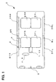
- the present embodiment is directed to an occupant protection system mounted on to a vehicle C (vehicle cabin), as shown in FIG. 1 .
- the vehicle C has occupant two seats on a vehicle front side and two occupant seats on a vehicle rear side, so that two seas are arranged in a vehicle width direction. Doors D are present in vicinity of respective seats to correspond to the seats.
- the vehicle C has four seats, which are a front right seat SFR, a front left seat SFL, a rear right seat SRR, and a rear left seat SRL.
- the vehicle C has four doors D, which are a front right door DFR, a front left door DFL, a rear right door DRR, and a rear left door DRL.
- a pillar BR is provided between the front right door DFR and the rear right door DRR.
- a pillar BL is provided between the front left door DFL and the rear left door DRL.
- the occupant protection system of the present embodiment includes an electronic control unit (ECU) 1 , a satellite sensor 2 , a steering wheel touch sensor 3 , a side airbag 4 and an acceleration sensor 5 .
- the satellite sensor 2 , the steering wheel touch sensor 3 and the side airbag 4 are connected to the ECU 1 via a communication line (not shown).
- the ECU 1 is arranged at substantially the center of the vehicle C.
- the ECU 1 determines a collision of the vehicle C (specifically, the collision necessitating protection of the occupant) and controls startup of the side airbag 4 .
- the ECU 1 is provided with a safing sensor 10 for detecting the impact on the vehicle and for ensuring redundancy to each sensor 2 , 5 .
- the ECU 1 corresponds to a determination device.
- the sensor 2 , 5 corresponds to a main sensor.
- the ECU 1 makes the collision determination by comparing a detection signal of each sensor 2 , 5 , 10 with a determination threshold. Specifically, a detection signal of each sensor 2 , 5 is processed. Specifically, in the present embodiment, a detection signal of each sensor 2 , 5 is integrated. When a processed value such as an integrated value exceeds the determination threshold, The ECU 1 determines the collision.
- the ECU 1 stores a determination threshold used for determining the primary collision, and a determination threshold used for determining the secondary collision.
- the determination threshold used for determining the primary collision is called herein a primary-collision determination threshold.
- the determination threshold used for determining the secondary collision is called herein a secondary-collision determination threshold, which includes a first secondary-collision determination and a second secondary-collision determination thresholds smaller than the first secondary-collision determination threshold.
- Each of the primary-collision determination threshold, the first secondary-collision determination threshold, and the second secondary-collision determination threshold generically includes determination thresholds corresponding to the detection signals of the satellite sensors 2 , 5 and the safing sensor 10 . That is, the primary-collision determination threshold has multiple determination thresholds for the determinations using the sensors 2 , 5 , 10 , respectively.
- the primary-collision determination threshold has a determination threshold for the determination using the sensor 5 and a determination threshold for the determination using the sensor 10 .
- the first secondary-collision determination threshold has a determination threshold for the determination using the sensor 2 and a determination threshold for the determination using the sensor 10 .
- the second secondary-collision determination threshold has a determination threshold for the determination using the sensor 2 and a determination threshold for the determination using the sensor 10 .
- the ECU 1 sets the determination thresholds used in determining the secondary-collision. Specifically, after occurrence of the primary collision of the vehicle C, the ECU 1 determines based on the detection result of the steering wheel touch sensor 3 whether the steering wheel H is gripped. When the steering wheel H is gripped by the occupant, the ECU 1 uses the first secondary-collision determination threshold to determine the secondary collision. When the steering wheel H is not gripped by the occupant, the ECU 1 uses the second secondary-collision determination threshold to determine the secondary collision.
- the steering wheel touch sensor 3 is provided on the steering wheel H of the vehicle C and detects whether or the steering wheel H is gripped by the occupant.
- an electrostatic capacitive sensor is used as the steering wheel touch sensor 3 .
- the steering wheel H of the vehicle C is to be gripped by the occupant (driver) seated on the front right seat SFR.
- the steering wheel touch sensor 3 corresponds to an occupant state detection device.
- the side airbag 4 is provided in a right side part of the vehicle to protect the occupant on the front right seat SFR.
- the side airbag 4 operates (starts up) in response to the startup signal from the ECU 1 .
- the acceleration sensor 5 is provided in a front part of the vehicle C (e.g., substantially the center of the front part) to detect the impact in a vehicle heading direction and a vehicle backing direction (vehicle front direction and vehicle rear direction).
- the vehicle C and the occupant protection system include other devices for protecting the occupant such as sensors (not shown), airbag and the like.
- the secondary collision refers to next collision after the vehicle is moved due to the occurrence of the primary collision.
- the secondary collision occurs within a specific time period after the primary collision.
- the specific time period is a predetermined short time period immediately after the primary collision.
- the primary collision occurs at the front left portion of the vehicle C, and then the impact of the primary collision rotates the vehicle C.
- the secondary collision which is another new collision, occurs at a right side of the vehicle.
- the detection signal of each sensor 2 , 3 , 5 , 10 is inputted to the ECU 1 at predetermined intervals (e.g., 0.5 milliseconds interval).
- FIG. 5 illustrates a flow of collision determination of the present embodiment.
- the acceleration sensor 5 and the safing sensor 10 detect the collision and transmit their detection results to the ECU 1 .
- the ECU 1 When ECU 1 receives the detection results of the two sensors 5 and 10 , the ECU 1 compares the integrated values, which are calculated from the detection results of respective sensors 5 and 10 , with the primary collision determination thresholds. When both of the two integrated values exceed the primary collision determination thresholds, the ECU 1 places the device (not shown) in operation and thereby protects the driver (occupant). In this collision, the determination of the primary collision and the protection of the occupant can be performed in substantially the same manner as in a conventional occupant protection system.
- the ECU 1 After the ECU 1 determines the primary collision, the ECU 1 refers the inputted detection signal of the steering wheel touch sensor 3 .
- the ECU 1 determines that a posture of the driver is maintainable. Specifically, the ECU 1 determines that the vehicle C is operable by the driver. In this case, the ECU 1 sets the first secondary-collision determination threshold as a next-used secondary-collision determination threshold.
- the ECU 1 determines that a posture of the driver is not maintainable. Specifically, the ECU 1 determines that the vehicle C is not operable by the driver. In this case, the ECU 1 sets the second secondary-collision determination threshold as a next-used secondary-collision determination threshold.
- the vehicle C may rotate counter clockwise.
- the right side of the vehicle C in the rotation direction may collide (secondary collision) with another object.
- the ECU 1 may determine based on the detection signal of the steering wheel touch sensor 3 that the steering wheel H is gripped by the driver. In this case, the ECU 1 sets the first secondary-collision determination threshold as the determination threshold for determining the secondary collision.
- the detection results of the sensors 2 , 10 are inputted to the ECU 1 and the ECU 1 makes the collision determination by using the first secondary-collision determination threshold in a manner similar to that in the primary collision.
- the ECU 1 compares the integrated values, which are calculated from respective detection results, with the first secondary-collision determination thresholds. When both of the two integrated values exceed the first secondary-collision determination thresholds, the ECU 1 determines that the occupant should be protected, and the ECU 1 issues a startup signal to start up the side airbag 4 . Upon receipt of the startup signal, the side airbag 4 starts up and protects the occupant.
- the secondary collision occurs and the sensors 2 and 10 detect the impact of the secondary collision.
- the detection results of the sensors 2 , 10 are inputted to the ECU 1 and the ECU 1 determines the collision determination by using the second secondary-collision determination threshold in a manner similar to that in the primary collision.
- the ECU 1 compares the integrated values, which are calculated from respective detection results, with the first secondary-collision determination thresholds. When both of the two integrated values exceed the second secondary-collision determination thresholds, the ECU 1 determines that the occupant should be protected, and the ECU 1 issues a startup signal to start up the side airbag 4 . Upon receipt of the startup signal, the side airbag 4 starts up and protects the occupant.
- the ECU 1 acquires the detection result of the steering wheel touch sensor 3 .
- the ECU 1 determines whether or not the driver is gripping the steering wheel H based on the detection result of the steering wheel touch sensor 3 .
- the process proceed to S 101 .
- the ECU 1 sets the second secondary-collision determination threshold as the determination threshold used for determining the secondary collision.
- the ECU 1 determines whether that the occupant should be protected against the secondary collision by comparing the detection results of the sensors 2 and 5 with the second secondary-collision determination thresholds.
- the process proceeds to S 107 . Otherwise, this process is ended.
- the process proceed to S 104 .
- the ECU 1 sets the first secondary-collision determination threshold as the determination threshold used for determining the secondary collision.
- the ECU 1 determines whether that the occupant should be protected against the secondary collision by comparing the detection results of the sensors 2 and 5 with the first secondary-collision determination thresholds.
- the process proceeds to S 107 . Otherwise, this process is ended.
- the ECU 1 transmits the startup signal to the airbag 4 .
- the airbag starts up to protect the occupant.
- the first secondary-collision determination threshold is used for the collision determination.
- the driver cannot maintain his posture, i.e., the driver cannot operate the vehicle C.
- the driver can gird himself for the secondary collision or can operate the vehicle to avoid the secondary collision, thereby reducing a damage degree to be suffered.
- the second secondary-collision determination threshold smaller than the first secondary-collision determination threshold is used for the collision determination.
- the driver cannot maintain his posture, i.e., the driver cannot operate vehicle C well. That is, when the driver is in this kind of state, the second secondary-collision determination threshold smaller than the first secondary-collision determination threshold is used for the collision determination.
- the second secondary-collision determination threshold is used, the determination of the secondary-collision is completed earlier. As a result, even if the driver cannot gird himself for the secondary collision or cannot operate the vehicle to avoid the secondary collision, a damage degree of the drive is reduced.
- the use of the secondary-collision determination threshold makes it possible to determine that the occupant should be protected. That is, even in a situation where the collision determination using the first secondary-collision determination threshold cannot determine the occurrence of the collision, the airbag 4 starts up to and protects the driver. Therefore, the present embodiment advantageously reduces the damage degree of the driver in the secondary collision occurring within a specific time period from the primary collision.
- the steering wheel touch sensor 3 provided on the steering wheel of the vehicle C is used to make a determination as to maintainability of the driver's posture, it is possible to not only determine whether the driver can maintain his posture but also determine whether the driver can operate the steering wheel to avoid the secondary collision. Therefore, this advantage reduces the damage degree of the driver.
- An occupant protection system of the present embodiment is the same as that of the first embodiment, except that the occupant protection system of the present embodiment includes a vehicle speed reduction device 6 .
- the occupant protection system of the present embodiment includes an electronic control unit (ECU) 1 , a satellite sensor 2 , a steering wheel touch sensor 3 , a side airbag 4 , an acceleration sensor 5 and a vehicle speed reduction device 6 .
- the satellite sensor 2 , the steering wheel touch sensor 3 , the side airbag 4 and the acceleration sensor 5 are the same as those in the first embodiment.
- the vehicle speed reduction device 6 is provided in a brake system of the vehicle C and reduces the speed of the vehicle in accordance with a signal from the ECU 1 .
- the vehicle speed reduction device 6 corresponds to a vehicle speed reduction device.
- the ECU 1 makes determinations of the primary collision and the secondary collision in a manner similar to those in the first embodiment.
- the ECU 1 issues a startup signal to the vehicle speed reduction device 6 .
- the vehicle speed reduction device 6 starts brake control to reduce the vehicle speed.
- the vehicle starts decelerating at the same time as the second secondary-collision determination threshold is set. As a result, the colliding speed in the secondary collision is reduced. The damage degree is further reduced.
- the vehicle speed reduction device 6 reduces the vehicle speed, occurrence of another accident is suppressed. For example, when the driver of the vehicle C involving the primary collision cannot maintain his posture, there is a fear that the vehicle movement may continue to bring about a new accident. However, in the present embodiment, because the vehicle speed reduction device 6 reduces the vehicle speed, it is possible to suppress a possibility that the vehicle C brings about a new collision (accident).
- the collision determination when it is determined after the primary collision that the driver is gripping the steering wheel, the collision determination is performed using the first secondary-collision determination threshold.
- the collision determination is performed using the second secondary-collision determination threshold.
- the occupant protection system of each above embodiment can advantageously reduce the damage degree of the driver.
- the steering wheel touch sensor 3 provided on the steering wheel H of the vehicle C is used as an occupant state detection device.
- the occupant state detection device is not limited to the sensor 3 . Any device capable of detecting whether the posture of the occupant is maintainable can be used as the occupant state detection device.
- the occupant state detection device may be a sensor provided on an arm rest of a vehicle (e.g., capacitive-type touch sensor, an infrared-type touch sensor), a device for detecting an occupant state by imaging a vehicle cabin, a device for detecting an occupant state by receiving a signal (e.g., radio wave, sound wave) from an occupant (e.g., a transmitter on an occupant), or the like.
- the sensors 2 , 5 , 10 are used as a sensor for detecting an impact at collision.
- type, total number, and the detection direction are not limited as long as a sensor can detect an impact at collision.
- the ECU 1 performs the collision determination by comparing the integrated value of the detection signal of each sensor 2 , 5 , 10 with the determination threshold.
- processing other than integration may be performed on the detection signal of each sensor 2 , 5 , 10 and the processed signal may be compared with the determination threshold.
- the signal outputted from each sensor 2 , 5 , 10 may be directly compared with the determination threshold.
- processing such as inversion, amplification or the like may be performed on the output signal and the processed signal may be compared with the determination threshold.
- the primary-collision determination threshold, the first secondary-collision determination threshold and the second secondary-collision determination threshold are predetermined.
- all or some of the determination thresholds may be calculated and determined based on the state of the vehicle C.
- each determination threshold may have any form as along as it can be compared with the detection signal of the sensor 2 , 5 , 10 to perform the collision determination.
- a determination threshold may be configured such that when the value obtained from the detection signal (e.g., the value of the processed signal) reaches (e.g., exceeds or falls below) the predetermined determination threshold, an occurrence of collision is determined.
- the value obtained from the detection signal goes out of a predetermined range (predetermined threshold range), an occurrence of collision may be determined.
- the primary-collision determination threshold is used for determining the primary collision
- the first and second secondary-collision determination thresholds are used for determining the secondary collision.
- the primary-collision determination threshold may be different from or not different (same) from one of the first and second secondary-collision determination thresholds.
- a shared determination threshold can be used.
- the side airbag 4 is used as a device for protecting an occupant after the collision determination.
- another device may be used alone or another device may be used in combination with the side airbag 4 .
- a device for protecting an occupant may include an airbag such as a driver seat airbag, a front passenger airbag, curtain airbag and the like, and may include a seat pretensioner.
- the vehicle speed reduction device 6 of the second embodiment is provided to a brake system.
- the vehicle speed reduction device 6 can be any device capable of reducing the vehicle speed.
- the vehicle speed reduction device 6 may be device provided to an engine or a drive-train of a vehicle. These devices may be used in combination. Additionally, it may be preferable that the vehicle speed reduction device 6 reduce the vehicle speed until the stop of the vehicle.
- the secondary collision is a collision occurring within the predetermined specific time period after the primary collision.
- the specific time period may be determined from the detection signal of each sensor 2 , 5 , and 10 .
- the specific time period may be a time period until convergence of the detection signal of the primary collision from each sensor 2 , 5 , 10 , i.e., until the stop of the vehicle.
- the above modifications can performs the collision determination in the primary collision and the secondary collision and protect the occupant like the above embodiment can. That is, the above modifications can have the same advantages as the above embodiments have.
Landscapes
- Engineering & Computer Science (AREA)
- Mechanical Engineering (AREA)
- Air Bags (AREA)
Applications Claiming Priority (2)
| Application Number | Priority Date | Filing Date | Title |
|---|---|---|---|
| JP2013119713A JP2014237341A (ja) | 2013-06-06 | 2013-06-06 | 乗員保護システム |
| JP2013-119713 | 2013-06-06 |
Publications (1)
| Publication Number | Publication Date |
|---|---|
| US8855884B1 true US8855884B1 (en) | 2014-10-07 |
Family
ID=51627040
Family Applications (1)
| Application Number | Title | Priority Date | Filing Date |
|---|---|---|---|
| US14/294,523 Expired - Fee Related US8855884B1 (en) | 2013-06-06 | 2014-06-03 | Occupant protection system |
Country Status (4)
| Country | Link |
|---|---|
| US (1) | US8855884B1 (ja) |
| JP (1) | JP2014237341A (ja) |
| CN (1) | CN104228742A (ja) |
| DE (1) | DE102014107618A1 (ja) |
Cited By (5)
| Publication number | Priority date | Publication date | Assignee | Title |
|---|---|---|---|---|
| US20150283968A1 (en) * | 2012-10-24 | 2015-10-08 | Autoliv Development Ab | Control device for occupant protection device |
| US20160325702A1 (en) * | 2012-10-24 | 2016-11-10 | Autoliv Development Ab | Control device for occupant protection device |
| US20180086206A1 (en) * | 2016-09-28 | 2018-03-29 | Yazaki Corporation | Vehicle-mounted equipment operation support system |
| US11335135B2 (en) * | 2016-05-06 | 2022-05-17 | Robert Bosch Gmbh | Method and device for determining accident effects on a vehicle |
| US20220185263A1 (en) * | 2020-12-16 | 2022-06-16 | Subaru Corporation | Aircraft and flight controller for aircraft |
Families Citing this family (4)
| Publication number | Priority date | Publication date | Assignee | Title |
|---|---|---|---|---|
| DE102015116142B4 (de) | 2015-09-24 | 2020-10-15 | Deutsche Telekom Ag | Verfahren und Anordnung zum Schutz von Insassen eines Kraftfahrzeugs |
| CN107776526A (zh) * | 2016-08-31 | 2018-03-09 | 比亚迪股份有限公司 | 安全气囊系统控制方法、气囊控制器和车辆 |
| CN111516630A (zh) * | 2020-05-09 | 2020-08-11 | 戴姆勒股份公司 | 碰撞防护系统及方法 |
| KR20210153266A (ko) | 2020-06-10 | 2021-12-17 | 현대모비스 주식회사 | 에어백 전개 제어 방법 및 장치 |
Citations (9)
| Publication number | Priority date | Publication date | Assignee | Title |
|---|---|---|---|---|
| JP2005280380A (ja) | 2004-03-26 | 2005-10-13 | Denso Corp | 車両用乗員保護装置 |
| US20060138759A1 (en) * | 2004-12-24 | 2006-06-29 | Takata Corporation | Detection system, occupant protection device, vehicle, and detection method |
| US20060186651A1 (en) * | 2005-02-18 | 2006-08-24 | Takata Corporation | Detection system, informing system, actuation system and vehicle |
| US7108280B2 (en) * | 2002-04-08 | 2006-09-19 | Takata Corporation | Vehicle occupant protection system |
| US20090140559A1 (en) * | 2007-11-30 | 2009-06-04 | Mazda Motor Corporation | Rear-seat occupant protection apparatus |
| US20110035116A1 (en) * | 2009-08-06 | 2011-02-10 | Aisin Seiki Kabushiki Kaisha | Occupant protection system for vehicle |
| US20110074190A1 (en) * | 2008-06-09 | 2011-03-31 | Syuzo Hashimoto | Occupant protection device |
| US20110098893A1 (en) * | 2007-08-13 | 2011-04-28 | Syuzo Hashimoto | Vehicle occupant protection device |
| US20110221247A1 (en) * | 2008-11-27 | 2011-09-15 | Toyota Jidosha Kabushiki Kaisha | Occupant protection device and control method thereof |
Family Cites Families (3)
| Publication number | Priority date | Publication date | Assignee | Title |
|---|---|---|---|---|
| JP3368721B2 (ja) * | 1995-05-29 | 2003-01-20 | トヨタ自動車株式会社 | 助手席用エアバッグ装置 |
| US7321311B2 (en) * | 2002-09-06 | 2008-01-22 | Continental Teves Ag & Co. Ohg | Steering handle for motor vehicles and method for recording a physical parameter on a steering handle |
| JP4900460B2 (ja) * | 2009-12-14 | 2012-03-21 | 株式会社デンソー | 操舵装置用車輪把持検出装置、プログラム |
-
2013
- 2013-06-06 JP JP2013119713A patent/JP2014237341A/ja active Pending
-
2014
- 2014-05-30 DE DE201410107618 patent/DE102014107618A1/de not_active Withdrawn
- 2014-06-03 US US14/294,523 patent/US8855884B1/en not_active Expired - Fee Related
- 2014-06-05 CN CN201410246762.XA patent/CN104228742A/zh active Pending
Patent Citations (12)
| Publication number | Priority date | Publication date | Assignee | Title |
|---|---|---|---|---|
| US7108280B2 (en) * | 2002-04-08 | 2006-09-19 | Takata Corporation | Vehicle occupant protection system |
| JP2005280380A (ja) | 2004-03-26 | 2005-10-13 | Denso Corp | 車両用乗員保護装置 |
| US20060138759A1 (en) * | 2004-12-24 | 2006-06-29 | Takata Corporation | Detection system, occupant protection device, vehicle, and detection method |
| US20060186651A1 (en) * | 2005-02-18 | 2006-08-24 | Takata Corporation | Detection system, informing system, actuation system and vehicle |
| US8059867B2 (en) * | 2005-02-18 | 2011-11-15 | Takata Corporation | Detection system, informing system, actuation system and vehicle |
| US20110098893A1 (en) * | 2007-08-13 | 2011-04-28 | Syuzo Hashimoto | Vehicle occupant protection device |
| US20090140559A1 (en) * | 2007-11-30 | 2009-06-04 | Mazda Motor Corporation | Rear-seat occupant protection apparatus |
| US7931332B2 (en) * | 2007-11-30 | 2011-04-26 | Mazda Motor Corporation | Rear-seat occupant protection apparatus |
| US20110074190A1 (en) * | 2008-06-09 | 2011-03-31 | Syuzo Hashimoto | Occupant protection device |
| US20110221247A1 (en) * | 2008-11-27 | 2011-09-15 | Toyota Jidosha Kabushiki Kaisha | Occupant protection device and control method thereof |
| US20110035116A1 (en) * | 2009-08-06 | 2011-02-10 | Aisin Seiki Kabushiki Kaisha | Occupant protection system for vehicle |
| US8630772B2 (en) * | 2009-08-06 | 2014-01-14 | Aisin Seiki Kabushiki Kaisha | Occupant protection system for vehicle |
Cited By (9)
| Publication number | Priority date | Publication date | Assignee | Title |
|---|---|---|---|---|
| US20150283968A1 (en) * | 2012-10-24 | 2015-10-08 | Autoliv Development Ab | Control device for occupant protection device |
| US9409535B2 (en) * | 2012-10-24 | 2016-08-09 | Autoliv Development Ab | Control device for occupant protection device |
| US20160325702A1 (en) * | 2012-10-24 | 2016-11-10 | Autoliv Development Ab | Control device for occupant protection device |
| US9751483B2 (en) * | 2012-10-24 | 2017-09-05 | Autoliv Development Ab | Control device for occupant protection device |
| US11335135B2 (en) * | 2016-05-06 | 2022-05-17 | Robert Bosch Gmbh | Method and device for determining accident effects on a vehicle |
| US20180086206A1 (en) * | 2016-09-28 | 2018-03-29 | Yazaki Corporation | Vehicle-mounted equipment operation support system |
| US10166868B2 (en) * | 2016-09-28 | 2019-01-01 | Yazaki Corporation | Vehicle-mounted equipment operation support system |
| US20220185263A1 (en) * | 2020-12-16 | 2022-06-16 | Subaru Corporation | Aircraft and flight controller for aircraft |
| US11993252B2 (en) * | 2020-12-16 | 2024-05-28 | Subaru Corporation | Vehicle control apparatus |
Also Published As
| Publication number | Publication date |
|---|---|
| DE102014107618A1 (de) | 2014-12-11 |
| JP2014237341A (ja) | 2014-12-18 |
| CN104228742A (zh) | 2014-12-24 |
Similar Documents
| Publication | Publication Date | Title |
|---|---|---|
| US8855884B1 (en) | Occupant protection system | |
| JP4501880B2 (ja) | 乗員保護装置 | |
| EP2048039B1 (en) | Post impact safety system with vehicle contact information. | |
| US8708366B2 (en) | Vehicle side impact detection using vehicle yaw | |
| US9415737B2 (en) | Vehicle occupant protection device | |
| JP6753324B2 (ja) | 車両用乗員保護装置及び車両用乗員保護方法 | |
| WO2013078093A1 (en) | System and method for determining when to deploy vehicle safety system | |
| US8903611B2 (en) | Vehicle-occupant protection system | |
| KR102131448B1 (ko) | 자동차의 승객 보호장치 | |
| US20190184926A1 (en) | Apparatus and method for controlling vehicular active seatbelt | |
| US9126552B2 (en) | Passenger protection system | |
| JP5803852B2 (ja) | 衝突検知装置及び乗員保護システム | |
| US10688949B2 (en) | Occupant protection device | |
| JP2005254921A (ja) | 車両用乗員保護装置 | |
| CN108128276A (zh) | 用于触发布置在机动车转向盘中的气囊的方法和触发电路 | |
| JP5041868B2 (ja) | 乗員拘束装置の起動システム | |
| KR20150062535A (ko) | 자동차의 승객보호장치 및 그 제어방법 | |
| JP5104847B2 (ja) | 乗員保護装置 | |
| KR101627502B1 (ko) | 자동차의 승객보호장치 | |
| JP7000087B2 (ja) | 車両の前面衝突検出装置 | |
| JP2018149987A (ja) | 乗員保護システム | |
| JP6394950B2 (ja) | 衝突検知装置および車両用非常通報装置 | |
| JP2013173387A (ja) | 車両衝突判定装置及び車両乗員保護システム | |
| JP2020158117A (ja) | 車両用乗員保護装置及び車両用乗員保護方法 | |
| EP2319733B1 (en) | Vehicle collision determination device |
Legal Events
| Date | Code | Title | Description |
|---|---|---|---|
| FEPP | Fee payment procedure |
Free format text: PAYOR NUMBER ASSIGNED (ORIGINAL EVENT CODE: ASPN); ENTITY STATUS OF PATENT OWNER: LARGE ENTITY |
|
| AS | Assignment |
Owner name: DENSO CORPORATION, JAPAN Free format text: ASSIGNMENT OF ASSIGNORS INTEREST;ASSIGNOR:FUJITSUKA, HIROSHI;REEL/FRAME:033018/0220 Effective date: 20140526 |
|
| FEPP | Fee payment procedure |
Free format text: MAINTENANCE FEE REMINDER MAILED (ORIGINAL EVENT CODE: REM.) |
|
| LAPS | Lapse for failure to pay maintenance fees |
Free format text: PATENT EXPIRED FOR FAILURE TO PAY MAINTENANCE FEES (ORIGINAL EVENT CODE: EXP.); ENTITY STATUS OF PATENT OWNER: LARGE ENTITY |
|
| STCH | Information on status: patent discontinuation |
Free format text: PATENT EXPIRED DUE TO NONPAYMENT OF MAINTENANCE FEES UNDER 37 CFR 1.362 |
|
| FP | Lapsed due to failure to pay maintenance fee |
Effective date: 20181007 |