US8824954B2 - Image forming apparatus - Google Patents
Image forming apparatus Download PDFInfo
- Publication number
- US8824954B2 US8824954B2 US13/602,843 US201213602843A US8824954B2 US 8824954 B2 US8824954 B2 US 8824954B2 US 201213602843 A US201213602843 A US 201213602843A US 8824954 B2 US8824954 B2 US 8824954B2
- Authority
- US
- United States
- Prior art keywords
- sheet
- curl correcting
- curl
- amount
- unit
- Prior art date
- Legal status (The legal status is an assumption and is not a legal conclusion. Google has not performed a legal analysis and makes no representation as to the accuracy of the status listed.)
- Active, expires
Links
- 238000011144 upstream manufacturing Methods 0.000 claims abstract description 18
- 230000008859 change Effects 0.000 claims abstract description 7
- 238000012545 processing Methods 0.000 claims description 21
- 230000002441 reversible effect Effects 0.000 claims description 11
- 238000000034 method Methods 0.000 claims description 10
- 230000008569 process Effects 0.000 claims description 7
- 238000012546 transfer Methods 0.000 description 51
- 238000003825 pressing Methods 0.000 description 14
- 238000012937 correction Methods 0.000 description 5
- 238000010586 diagram Methods 0.000 description 4
- 230000000694 effects Effects 0.000 description 4
- 238000010438 heat treatment Methods 0.000 description 2
- 230000002035 prolonged effect Effects 0.000 description 2
- 238000004080 punching Methods 0.000 description 2
- 230000002123 temporal effect Effects 0.000 description 2
- 230000008901 benefit Effects 0.000 description 1
- 239000000969 carrier Substances 0.000 description 1
- 230000007613 environmental effect Effects 0.000 description 1
- 238000012986 modification Methods 0.000 description 1
- 230000004048 modification Effects 0.000 description 1
Images


Classifications
-
- G—PHYSICS
- G03—PHOTOGRAPHY; CINEMATOGRAPHY; ANALOGOUS TECHNIQUES USING WAVES OTHER THAN OPTICAL WAVES; ELECTROGRAPHY; HOLOGRAPHY
- G03G—ELECTROGRAPHY; ELECTROPHOTOGRAPHY; MAGNETOGRAPHY
- G03G15/00—Apparatus for electrographic processes using a charge pattern
- G03G15/65—Apparatus which relate to the handling of copy material
- G03G15/6555—Handling of sheet copy material taking place in a specific part of the copy material feeding path
- G03G15/6573—Feeding path after the fixing point and up to the discharge tray or the finisher, e.g. special treatment of copy material to compensate for effects from the fixing
- G03G15/6576—Decurling of sheet material
Definitions
- This invention relates to an image forming apparatus and more specifically to the image forming apparatus including a curl correcting unit configured to correct a curl caused in a sheet.
- an image forming apparatus such as a copier and a printer is configured to transfer a toner image formed in an image forming unit thereof on a sheet fed from a sheet feeding portion and then to guide the sheet to a fixing unit to fix the toner image on the sheet.
- fixing units there is a thermal pressure fixing-type fixing unit configured to fix the toner image on the sheet by pressurizing and heating the sheet passing through the fixing unit.
- a sheet processing unit to be able to readily carry out such processes as sorting, stapling, punching and book-binding of the sheets.
- the sheet on which the toner image has been fixed in the fixing unit is liable to cause a curl by absorbing moisture condensed on a guide of the fixing unit and vapor in a surrounding area. If the sheet thus curls, there is a possibility of not only causing jamming of the sheet but also of dropping performance in stacking the sheet on a tray after its discharge. Then, in order to correct such a curl of the sheet, there is one provided with a curl correcting unit between the image forming apparatus and the sheet processing unit.
- a roller nip-type curl correcting unit composed of an elastic roller and a pressure roller that rotates while forming a curved nip portion by pressurizing the elastic roller.
- the curl correcting unit is configured to correct (to straighten) the sheet so as to have no curl by temporarily curving and deforming the sheet in a direction opposite from a direction in which the sheet is curled.
- the curl correcting unit is configured to able to adequately correct the curl by adjusting a force of the pressure roller, i.e., an amount of bite of the pressure roller to the elastic roller, corresponding to such detected information.
- Japanese Patent Application Laid-open No. 2007-161398 discloses an arrangement of increasing the pressurizing force in connection with the increase of the sheet conveying speed.
- some image forming apparatuses include a consolidated mode of forming images on different types of sheets and of conveying the sheets to the sheet processing unit in one JOB.
- a degree of curl of the sheet is different depending on the types of sheets, it is necessary to switch the amount of bite of the pressure roller to the elastic roller in such consolidated mode corresponding to the respective types of sheets.
- an image forming apparatus configured to be able to securely correct a curl of a sheet.
- FIG. 1 is a perspective view of a color laser printer, i.e., an exemplary image forming apparatus, of an embodiment of the invention.
- FIG. 2 illustrates a schematic configuration of the color laser printer.
- FIG. 3 illustrates a configuration of a curl correcting unit provided in a buffer unit of the color laser printer.
- FIG. 4 is a control block diagram of the curl correcting unit.
- FIG. 5 is a flowchart of a bite switching control in a consolidated mode of the curl correcting unit.
- FIG. 6A is a diagram explaining a curl correcting operation in a front edge pressurizing mode of the curl correcting portion provided in the curl correcting unit.
- FIG. 6B is a diagram explaining a curl correcting operation in a rear edge pressurizing mode of the curl correcting portion.
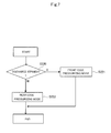
- FIG. 7 is a flowchart illustrating an operation for switching the pressing modes of the curl correcting portion.
- FIG. 1 is a perspective view of a color laser printer, i.e., an exemplary image forming apparatus, of an embodiment of the invention
- FIG. 2 illustrates a schematic configuration thereof.
- FIGS. 1 and 2 show the color laser printer 1 that includes a printer body 1 A, i.e., a body of the image forming apparatus, and a sheet processing unit 2 connected at one side of the printer body 1 A and configured to perform such processes as folding, stapling, punching and book-binding processes. Still further, a buffer unit 3 having a curl correcting unit described later is provided between the printer body 1 A and the sheet processing unit 2 .
- the printer body 1 A is provided with an image forming unit 1 B, an intermediate transfer portion 1 C, a fixing unit 45 , a sheet feeding unit 1 D for feeding a sheet S to the image forming unit 1 B, and a manual sheet feeding unit 30 for feeding a sheet manually supplied.
- the color laser printer 1 is configured to be able to form an image on a back of a sheet and is provided with a re-conveying portion 1 E so that a sheet S on which an image has been formed on a surface (first surface) thereof is reversed and is conveyed again to the image forming unit 1 B.
- the image forming unit 1 B is provided with four processing stations 60 , i.e., 60 Y, 60 M, 60 C and 60 K, that form four color toner images of yellow (Y), magenta (M), cyan (C), and black (Bk), respectively.
- These processing stations are provided with photosensitive drums 61 , i.e., image carriers 61 Y, 61 M, 61 C and 61 K, that carry the four color toner images of yellow, magenta, cyan, and black and driven by stepping motor not shown, and with chargers 62 , i.e., 62 Y, 62 M, 62 C and 62 K, configured to uniformly charge surfaces of the photosensitive drums, respectively.
- the processing stations are also provided with scanners 63 , i.e., 63 Y, 63 M, 63 C and 63 K, that irradiate laser beams respectively to the photosensitive drums that rotate with constant speed based on image data to form electrostatic latent images thereon.
- the processing stations are also provided with developers 64 , i.e., 64 Y, 64 M, 64 C and 64 K that apply toners of yellow, magenta, cyan, and black to the electrostatic latent images formed on the photosensitive drums to visualize as toner images.
- the chargers 62 , the scanners 63 , the developers 64 and others are disposed around the photosensitive drums 61 respectively along a rotating direction of the respective drums.
- the sheet feeding unit 1 D is provided at an under part of the printer body and is provided with sheet feeding cassettes 31 through 34 , i.e., sheet storage portions for storing the sheets S, and pickup rollers 36 through 39 that send out the sheets S stacked and stored in the sheet feeding cassettes 31 through 34 .
- the manual sheet feeding unit 30 includes a manual feed tray 30 a , i.e., a sheet storing portion for stacking and storing the sheets S, and a sheet feeding roller 35 being configured to feed the sheet S stacked on the manual feed tray 30 a.
- the sheet S is separated and fed one by one by the pickup rollers 36 through 39 from the sheet feeding cassettes 31 through 34 , passes through a vertical conveying path 41 and is conveyed to a registration roller 42 .
- the sheet S stacked in the manual feed tray 30 a is conveyed to the registration roller 42 by the feed roller 35 by passing through a conveying path 40 .
- the registration roller 42 has a function of adjusting the front edge of the sheet S to correct oblique motion thereof by butting the sheet S and creating a loop thereof.
- the registration roller 42 also has a function of conveying the sheet S to a secondary transfer portion by predetermined timing conforming to timing for forming an image on the sheet S, i.e., in conformity with the toner image carried on an intermediate transfer belt described below.
- the intermediate transfer portion 1 C has the intermediate transfer belt 67 that is rotationally driven in a direction in which the respective processing stations are arrayed as shown by an arrow B in FIG. 2 in synchronism with outer circumferential speed of the photosensitive drum 61 .
- the intermediate transfer belt 67 is stretched around a driving roller 69 , a driven roller 70 that forms a secondary transfer area by interposing the intermediate transfer belt 67 , and a tension roller 68 that applies adequate tension to the intermediate transfer belt 67 by urging force of a spring not shown.
- Four primary transfer rollers 66 i.e., 66 Y, 66 M, 66 C and 66 K that nip the intermediate transfer belt 67 together with the respective photosensitive drums 61 and compose primary transfer portions are arrayed on the inside of the intermediate transfer belt 67 . It is noted that these primary transfer rollers 66 are connected with a transfer biasing power source not shown. The respective color images on the photosensitive drums are superimposed and transferred sequentially on the intermediate transfer belt 67 and a full-color image is formed on the intermediate transfer belt 67 by transfer bias applied from the primary transfer rollers 66 to the intermediate transfer belt 67 .
- a secondary transfer roller 43 is disposed so as to face to the driven roller 70 .
- This secondary transfer roller 43 contacts a surface of the intermediate transfer belt 67 at a lowest part thereof and nips and conveys the sheet S conveyed by the registration roller 42 together with the intermediate transfer belt 67 .
- the toner image on the intermediate transfer belt 67 is secondarily transferred to the sheet S by the bias voltage applied to the secondary transfer roller 43 when the sheet S passes through a nip portion between the secondary transfer roller 43 and the intermediate transfer belt 67 .
- the fixing unit 45 is configured to fix the toner image formed on the sheet S through the intermediate transfer belt 67 on the sheet S. That is, the toner image is fixed on the sheet S by being applied with heat and pressure when the sheet S carrying the toner image passes through the fixing unit 45 .
- the scanner 63 Y irradiates laser to the photosensitive drum 61 Y to form a yellow latent image on the photosensitive drum 61 Y in the processing station 60 Y located at a most upstream side in the rotational direction of the intermediate transfer belt 67 at first.
- the developer 64 Y develops this latent image by yellow toner to form the yellow toner image.
- the yellow toner image formed on the photosensitive drum 61 Y as described above is transferred primarily to the intermediate transfer belt 67 in the primary transfer area by the transfer roller 66 to which high voltage is applied. Then, the toner image is conveyed together with the intermediate transfer belt 67 to a next primary transfer area composed of the photosensitive drum 61 M and the transfer roller 66 M of the processing station 60 M in which the image is formed behind the processing station 60 Y by a time during which the magenta toner image is conveyed.
- next magenta toner image is transferred on the yellow toner image on the intermediate transfer belt 67 by aligning the front edge of the images.
- the same processes are repeated after that and as a result, the four color toner images are transferred primarily on the intermediate transfer belt 67 and the full-color image is formed on the intermediate transfer belt 67 .
- photosensitive drum cleaners 65 i.e., 65 Y, 65 M, 65 C and 65 K recover remaining transfer toner slightly left on the photosensitive drums to be ready to form a next image.
- the sheet S stored in the feeding cassettes 31 through 34 for example is separated and fed one by one by the pickup rollers 36 through 39 and is then conveyed to the registration roller 42 .
- the sheet S stacked on the manual feed tray 30 a is conveyed to the registration roller 42 by the sheet feeding roller 35 by passing through the conveying path 40 .
- the registration roller 42 is stopped at this time, so that the oblique motion of the sheet S is corrected by butting against the registration roller 42 in the stopped state.
- the sheet S is conveyed to the nip portion between the secondary transfer roller 43 and the intermediate transfer belt 67 by the registration roller 42 that starts its rotation with timing when the front edge of the sheet coincides with the toner image formed on the intermediate transfer belt 67 .
- the toner image on the intermediate transfer belt 67 is transferred secondarily on the sheet S by the bias voltage applied to the secondary transfer roller 43 .
- the sheet S on which the toner image has been secondarily transferred is then conveyed to the fixing unit 45 by a pre-fixing conveying unit 44 .
- the fixing unit 45 is configured to melt and fix the toner image on the sheet S by applying a predetermined pressurizing force by rollers, belts or the like opposing with each other and a heating effect by a heat source such as a heater in general.
- a heat source such as a heater in general.
- the sheet S When images are to be formed on both sides of the sheet S, the sheet S is sent to a reverse guide path 52 by a path switching portion not shown. After that, the sheet S is pulled into a switchback path 55 from the reverse guide path 52 by a reversing upper and lower rollers 53 and 54 to switch the front and rear edges of the sheet S by performing a switch-back operation of reversing a rotational direction of the reversing lower roller 54 , and to convey to a duplex conveying path 47 .
- the sheet S confluents again by adjusting timing with a succeeding sheet S conveyed by the pickup rollers 36 through 39 or the feed roller 35 by conveyor rollers 48 a through 48 d provided along the duplex conveying path 47 .
- the sheet S is sent to the secondary transfer portion through the registration roller 42 . It is noted that the image forming process implemented on the back (second surface) after that is the same with that of the surface (first surface) as already described above.
- the sheet S is pulled into the switchback path 55 from the reverse guide path 52 by the reversing upper and lower rollers 53 and 54 .
- the reversing upper and lower rollers 53 and 54 are rotated reversely to convey the sheet S to a reverse conveying path 56 , i.e., a reverse conveying path, in a direction opposite from the direction in which the sheet S has been pulled in by reversing the rear edge as the front edge.
- the sheet S is reversely discharged out to the sheet processing unit 2 by the outer discharge roller 49 so that a downstream end and an upstream end in a sheet conveying direction of the sheet S is reversed.
- the sheet S guided by the discharge conveying path 51 or the reverse conveying path 56 and is discharged out of the printer body 1 A by the outer discharge roller 49 is conveyed to a buffer path 81 provided in the buffer unit 3 . Then, the sheet S is conveyed to a finisher conveying path 82 provided in the sheet processing unit 2 and is discharged to a discharge tray 2 a after being processed in the sheet processing unit 2 .
- the sheet heated and fixed by the fixing unit 45 is liable to cause a curl by absorbing moisture condensed on the guide and surrounding vapor. Then, when the sheet curls, there is a possibility of causing not only jamming but also drop of performance in stacking the sheet on the discharge tray after the discharge. Then, a curl correcting unit configured to correct a curl of the sheet S is provided along the buffer path 81 of the buffer unit 3 in the present embodiment.
- FIG. 3 illustrates a configuration of such curl correcting unit 3 A.
- the curl correcting unit 3 A includes a first curl correcting portion 91 that corrects a curl in a first direction of the sheet, e.g., a downward curl that bulges a center part of the sheet upward.
- the curl correcting unit 3 A also includes a second curl correcting portion 92 provided downstream in the sheet conveying direction of the first curl correcting portion 91 to correct a curl in a second direction of the sheet, e.g., an upward curl by which front and rear edge portions of the sheet bulge upward.
- the first curl correcting portion 91 is provided with a pair of curl correcting rollers of an elastic roller 94 a and a stationary roller (metallic roller) 93 a whose hardness is high and which press-contacts the elastic roller 94 a from above (first direction).
- the stationary roller 93 a bites into the elastic roller 94 a from above and form a nip portion 95 a curved downward by press-contacting the pair of rollers 93 a and 94 a whose hardness is different.
- the second curl correcting portion 92 is also provided with a pair of curl correcting rollers of an elastic roller 94 b and a stationary roller 93 b which bites into the elastic roller 94 b from below (second direction) to form a nip portion 95 b curved upward in an opposite direction from that of the nip portion 95 a of the first curl correcting portion 91 .
- the sheet S passes through the curl correcting unit 3 A provided with the first and second curl correcting portions 91 and 92 having the nip portions 95 a and 95 b whose curved portions are different as described above, the sheet S is curved and deformed temporarily downward in a vertical direction with respect to a conveying surface by the first curl correcting portion 91 at first. Thereby, the downward curl of the sheet S is corrected (straightened). Then, when the sheet S passes through the second curl correcting portion 92 , the sheet S is curved and deformed temporarily upward in the vertical direction. Thereby, the upward curl is corrected (straightened).
- the curl correcting unit 3 A is provided with bite modifying portions 91 a and 92 a configured to modify an amount of bite of the stationary roller 93 into the elastic roller 94 , i.e., curved amount modifying portions configured to modify an amount of curve of the nip portion, by changing position of the elastic roller 94 corresponding to the type of the sheet S.
- the bite modifying portion 91 a of the first curl correction portion 91 includes a cam 96 a that is rotated by a bite control motor M 1 shown in FIG. 4 and described later, and a link 98 a provided with a roller 97 a that abuts the cam 96 at first end thereof and rotatably supports the elastic roller 94 .
- the bite modifying portion 92 a of the second curl correcting portion 92 is constructed in the same manner with the bite modifying portion 91 a of the first curl correcting portion 91 .
- level of the curve of the nip portion 95 composed of the stationary roller 93 and the elastic roller 94 i.e., the amounts of bite of the stationary roller 93 into the elastic roller 94 , is changed depending on the type of the sheet S to perform the curl correction suitable to the type of the sheet S.
- FIG. 4 is a control block diagram of the curl correcting unit 3 A configured to vary the curl correcting amount.
- FIG. 4 shows a CPU (control unit) 100 and an input portion 101 , such as a manipulating portion provided on the printer body 1 A, for inputting information such as sheet information concerning the type of the sheet S and mode information such as a discharge mode described later, the consolidated mode, a front edge pressing mode and a rear edge pressing mode to the CPU 100 .
- the CPU 100 drives the bite control motors M 1 and M 2 to set the curl correcting amount set in advance corresponding to the types of the sheets.
- the input portion 101 may be configured to input the curl correcting amount corresponding to the type of the sheet. Still further, the input portion 101 may be provided with a detector (sensor) not shown for detecting the type of the sheet along the conveying path, other than the manipulating portion, so that the CPU 100 can detect the type of the sheet based on a signal from the detector.
- a detector sensor
- FIG. 4 also shows a path sensor SN disposed upstream of the sheet conveying direction of the curl correcting unit 3 A to detect passage of the front edge of the sheet.
- the CPU 100 drives the bite control motors M 1 and M 2 based on a signal from the path sensor SN. It is noted that the CPU 100 may be provided either in the printer body 1 A or in the buffer unit 3 .
- the laser printer 1 of the present embodiment is provided with the consolidated mode of forming images sequentially on different types of sheets and of conveying the sheets to the sheet processing unit 2 in one Job.
- the amount of bite is switched corresponding to the types of the sheets. Then, control for switching the amounts of bite in the consolidated mode will be explained below with reference to FIG. 5 .
- the CPU 100 judges whether or not mode information inputted through the input portion 101 is the consolidated mode in Step S 200 . Then, when the mode information is the consolidated mode, i.e., Yes in Step S 200 , the CPU 100 sets amounts of bite of a first sheet in the first and second curl correcting portions 91 and 92 in accordance to user's input value input through the input portion 101 by the user in Step S 201 and starts the JOB in Step S 202 .
- the sheet is conveyed to the first and second curl correcting portions 91 and 92 for which the amounts of bite are set as described above to correct the curl of the sheet in Step S 203 .
- the CPU 100 judges whether or not the sheet is a final sheet in Step S 204 and when the sheet is not a final sheet, i.e., No in Step S 204 , the CPU 100 judges whether nor not the succeeding sheet is a different type of sheet in Step S 205 .
- the CPU 100 judges that the succeeding sheet is a different type of sheet here, i.e., Yes in Step S 205 , the CPU 100 waits for time when the path sensor detects a front edge of the succeeding sheet in Step S 206 .
- Step S 206 When the path sensor detects the front edge of the succeeding sheet, i.e., Yes in Step S 206 , the CPU 100 sets amounts of bite again based on information concerning the type of the succeeding sheet in Step S 207 . Then, the sheet is conveyed to the first and second curl correcting portions 91 and 92 for which the amounts of bite are set again as described above to correct a curl of the different type of the sheet in Step S 203 . After that, by detecting the final sheet, i.e., Yes in Step S 204 , the CPU 100 ends the JOB.
- the CPU 100 judges that the succeeding sheet is the same type of sheet, i.e., No in Step S 205 , the CPU 100 conveys the sheet to the first and second curl correcting portions 91 and 92 for which the same amounts of bite are set to correct the curl of the sheet in Step S 203 . Still further, when the mode information is not the consolidated mode, i.e., Yes in Step S 200 , the CPU 100 sets amounts of bite of the first and second curl correcting portions 91 and 92 in accordance to the user's input values input through the input portion 101 by the user in Step S 210 and then starts the JOB in Step S 211 .
- the sheet is conveyed to the first and second curl correcting portions 91 and 92 for which the amounts of bite are set as described above to correct the curl of the sheet in Step S 212 .
- the CPU 100 judges whether or not the sheet is a final sheet in Step S 213 and when the sheet is not a final sheet, i.e., No in Step S 213 , the curls of the sheets are corrected continuously in Step S 212 .
- detecting the final sheet i.e., Yes in Step S 213 , the CPU 100 ends the JOB.
- the CPU 100 of the present embodiment is arranged to start the bite switching operation, i.e., the operation of moving the elastic roller 94 in a direction of an arrow shown in FIG. 6A , until the rear edge of the preceding sheet S 1 passes through the nip portion 95 .
- the operation of moving the elastic roller 94 in the direction of the arrow is started after pressing a pressure range P of the sheet including the front edge portion of the preceding sheet S 1 with a predetermined amount of bite.
- a switching time t for performing the bite switching operation can be a total time of a time t 1 from when the rear end of the pressure range P including the front edge of the preceding sheet passes through the nip portion 95 until when the rear edge of the preceding sheet reaches the nip portion 95 and a sheet interval time t 2 . That is, the switching time t for performing the bite switching operation can be prolonged more than the sheet interval time t 2 by the time t 1 from when the rear end of the pressure range P including the front edge of the preceding sheet passes through the nip portion 95 until when the rear edge of the preceding sheet reaches the nip portion 95 . Then, it is possible to complete the switching operation until the front edge of the succeeding sheet S 2 enters the nip portion 95 by prolonging the switching time t as described above.
- the mode of switching the amounts of bite in a range of the rear edge of the preceding sheet and the sheet interval to correct a curl on the front edge part of the sheet as described above will be referred to as the front edge pressing mode (first mode).
- the pressure range P 1 is set from the front edge of the sheet to an intermediate portion of the sheet and switching of the amounts of bite is started when the rear end of the pressure range P passes through the nip portion 95 in the front edge pressing mode.
- the CPU 100 controls so as to start the operation of moving the elastic roller 94 in the direction of the arrow until the front edge portion of the succeeding sheet S 2 reaches the nip portion 95 after pressing the pressure range P 2 including the rear edge of the preceding sheet S 1 .
- the switching time t for performing the bite switching operation can be a total time of the sheet interval time t 2 and a time 3 from when the front edge of the succeeding sheet S 2 reaches the nip portion 95 till when the front of the pressure range P 2 reaches the nip portion 95 . That is, the switching time t for performing the bite switching operation can be prolonged more than the sheet interval time t 2 by the time t 3 from when the front edge of the succeeding sheet S 2 reaches the nip portion 95 till when the front of the pressure range p 2 reaches the nip portion 95 .
- the mode of switching the amounts of bite in the sheet interval and in the front edge portion of the succeeding sheet to correct a curl on the rear edge part of the sheet as described above will be referred to as a rear edge pressing mode (second mode) hereinafter.
- the pressure range P 2 is set from the intermediate portion to the rear edge of the sheet and switching of the amounts of bite is started when the rear edge of the preceding sheet P 1 passes through the nip portion 95 in the rear edge pressing mode.
- FIG. 7 is a flowchart illustrating an operation for switching the pressing modes in changing the amount of bite between the preceding sheet and the following succeeding sheet.
- the CPU 100 judges whether or not discharge mode information input through the input portion 101 is straight discharge in Step S 220 .
- the discharge mode information is straight discharge, i.e., Yes in Step S 220
- the curl correction in the front edge pressing mode shown in FIG. 6A is carried out.
- the discharge mode information is not straight discharge, i.e., No in Step S 220
- the curl correction in the rear edge pressing mode as shown in FIG. 6B is carried out.
- the CPU 100 is capable of selectively executing the front edge pressing mode when the preceding sheet 51 is conveyed to the pair of curl correcting rollers (curl correcting unit) through the discharge conveying path 51 , and the rear edge pressing mode when the preceding sheet 51 is conveyed to the pair of curl correcting rollers (curl correcting unit) through the reverse conveying path 56 .
- the curl correcting amount is changed to a curl correcting amount corresponding to the type of the succeeding sheet in the present embodiment. Then, when the sheet is a sheet whose downstream part in the sheet conveying direction is curled, the present embodiment is arranged so that the change of the curl correcting amount is finished from when the downstream part in the sheet conveying direction of the preceding sheet passes through the curl correcting unit until when the succeeding sheet reaches the curl correcting unit.
- the present embodiment is arranged so that the change of the curl correcting amount of the curl correcting unit is finished from when the preceding sheet passes through the curl correcting unit until when the upstream part in the sheet conveying direction of the succeeding sheet reaches the curl correcting unit.
- the timing of starting to change the curl correcting amount is changed corresponding to the curled part of the sheet in the present embodiment.
- the two curl correcting portions i.e., the plurality of curl correcting portions, have been disposed in the curl correcting unit 3 A in the present embodiment, the curl correcting portion may be one or may be three or more to more securely correct the curl.
- aspects of the present invention can also be realized by a computer (such as a CPU or MPU) of a system or apparatus that reads out and executes a program recorded on a memory device to perform the functions of the above-described embodiment, and by a method, the steps of which are performed by a computer of a system or apparatus by, for example, reading out and executing a program recorded on a memory device to perform the functions of the above-described embodiment.
- the program is provided to the computer for example via a network or from a recording medium of various types serving as the memory device, e.g., computer-readable medium.
- a computer-readable storage medium may store a program that causes a sheet storage apparatus to perform a method described herein.
- a central processing unit may be configured to control at least one unit utilized in a method or apparatus described herein.
Landscapes
- Physics & Mathematics (AREA)
- General Physics & Mathematics (AREA)
- Separation, Sorting, Adjustment, Or Bending Of Sheets To Be Conveyed (AREA)
- Delivering By Means Of Belts And Rollers (AREA)
Applications Claiming Priority (2)
| Application Number | Priority Date | Filing Date | Title |
|---|---|---|---|
| JP2011265734A JP5911277B2 (ja) | 2011-12-05 | 2011-12-05 | 画像形成装置 |
| JP2011-265734 | 2011-12-05 |
Publications (2)
| Publication Number | Publication Date |
|---|---|
| US20130142556A1 US20130142556A1 (en) | 2013-06-06 |
| US8824954B2 true US8824954B2 (en) | 2014-09-02 |
Family
ID=48524110
Family Applications (1)
| Application Number | Title | Priority Date | Filing Date |
|---|---|---|---|
| US13/602,843 Active 2032-10-19 US8824954B2 (en) | 2011-12-05 | 2012-09-04 | Image forming apparatus |
Country Status (2)
| Country | Link |
|---|---|
| US (1) | US8824954B2 (enExample) |
| JP (1) | JP5911277B2 (enExample) |
Cited By (3)
| Publication number | Priority date | Publication date | Assignee | Title |
|---|---|---|---|---|
| US9835997B2 (en) * | 2014-07-25 | 2017-12-05 | Konica Minolta, Inc. | Image forming apparatus having conveyance roller section with nip angle adjusting section |
| US11586130B2 (en) | 2021-02-25 | 2023-02-21 | Canon Kabushiki Kaisha | Image forming apparatus with guiding member fixed to guiding member to form feeding path of recording material |
| US11586131B2 (en) | 2021-02-25 | 2023-02-21 | Canon Kabushiki Kaisha | Image forming apparatus with guiding member configured to guide recording material and being fixed to holding member configured to hold roller |
Families Citing this family (2)
| Publication number | Priority date | Publication date | Assignee | Title |
|---|---|---|---|---|
| US9517906B2 (en) | 2012-08-29 | 2016-12-13 | Canon Kabushiki Kaisha | Conveying guide, sheet conveying apparatus, and image forming apparatus |
| JP6217689B2 (ja) * | 2015-05-01 | 2017-10-25 | コニカミノルタ株式会社 | 用紙加湿装置及び加湿制御方法 |
Citations (13)
| Publication number | Priority date | Publication date | Assignee | Title |
|---|---|---|---|---|
| US5824408A (en) | 1995-04-28 | 1998-10-20 | Canon Kabushiki Kaisha | White electroconductive coating composition and transfer material-carrying member |
| US5848347A (en) * | 1997-04-11 | 1998-12-08 | Xerox Corporation | Dual decurler and control mechanism therefor |
| US5920751A (en) * | 1998-01-08 | 1999-07-06 | Xerox Corporation | Apparatus and method for controlling moisture and cooling rate for paper curl reduction |
| US6023597A (en) | 1995-05-30 | 2000-02-08 | Canon Kabushiki Kaisha | Cellular conductive roller with conductive powder filling open cells in the surface |
| US6259888B1 (en) * | 1999-02-09 | 2001-07-10 | Fuji Xerox Co., Ltd. | Curl correcting unit and image forming apparatus |
| US20050063747A1 (en) * | 2003-09-22 | 2005-03-24 | Canon Kabushiki Kaisha | Curl correcting device and image forming apparatus |
| US20070132174A1 (en) | 2005-12-13 | 2007-06-14 | Konica Minolta Business Technologies, Inc. | Image forming apparatus and sheet material conveyance device used therein |
| US20080050164A1 (en) * | 2006-08-23 | 2008-02-28 | Canon Kabushiki Kaisha | Printing apparatus and conveyance control method |
| US20090003912A1 (en) * | 2007-06-26 | 2009-01-01 | Canon Kabushiki Kaisha | Curl correcting device and image forming apparatus |
| US20100135708A1 (en) * | 2008-12-02 | 2010-06-03 | Ricoh Company, Limited | Curl correcting device, image forming apparatus, and sheet post-processing device |
| US20110097127A1 (en) * | 2009-10-27 | 2011-04-28 | Canon Kabushiki Kaisha | Method of correcting curl of sheet and recording apparatus |
| US20110236102A1 (en) * | 2010-03-25 | 2011-09-29 | Kyocera Mita Corporation | Sheet curl correction apparatus and image forming apparatus |
| US8265541B2 (en) * | 2008-06-18 | 2012-09-11 | Konica Minolta Business Technologies, Inc. | Sheet processing apparatus and image forming system which corrects a curl |
Family Cites Families (3)
| Publication number | Priority date | Publication date | Assignee | Title |
|---|---|---|---|---|
| JP2000227694A (ja) * | 1999-02-08 | 2000-08-15 | Fuji Xerox Co Ltd | 画像形成装置 |
| JP2003012215A (ja) * | 2001-06-28 | 2003-01-15 | Konica Corp | 紙搬送装置、画像形成装置及び後処理装置 |
| JP2004315181A (ja) * | 2003-04-17 | 2004-11-11 | Canon Inc | 画像形成装置のカール修正装置 |
-
2011
- 2011-12-05 JP JP2011265734A patent/JP5911277B2/ja active Active
-
2012
- 2012-09-04 US US13/602,843 patent/US8824954B2/en active Active
Patent Citations (15)
| Publication number | Priority date | Publication date | Assignee | Title |
|---|---|---|---|---|
| US5824408A (en) | 1995-04-28 | 1998-10-20 | Canon Kabushiki Kaisha | White electroconductive coating composition and transfer material-carrying member |
| US6023597A (en) | 1995-05-30 | 2000-02-08 | Canon Kabushiki Kaisha | Cellular conductive roller with conductive powder filling open cells in the surface |
| US5848347A (en) * | 1997-04-11 | 1998-12-08 | Xerox Corporation | Dual decurler and control mechanism therefor |
| US5920751A (en) * | 1998-01-08 | 1999-07-06 | Xerox Corporation | Apparatus and method for controlling moisture and cooling rate for paper curl reduction |
| US6259888B1 (en) * | 1999-02-09 | 2001-07-10 | Fuji Xerox Co., Ltd. | Curl correcting unit and image forming apparatus |
| US20050063747A1 (en) * | 2003-09-22 | 2005-03-24 | Canon Kabushiki Kaisha | Curl correcting device and image forming apparatus |
| US20070132174A1 (en) | 2005-12-13 | 2007-06-14 | Konica Minolta Business Technologies, Inc. | Image forming apparatus and sheet material conveyance device used therein |
| JP2007161398A (ja) | 2005-12-13 | 2007-06-28 | Konica Minolta Business Technologies Inc | 画像形成装置、画像形成方法及びシート材搬送装置 |
| US7654519B2 (en) | 2005-12-13 | 2010-02-02 | Konica Minolta Business Technologies, Inc. | Image forming apparatus and sheet material conveyance device used therein |
| US20080050164A1 (en) * | 2006-08-23 | 2008-02-28 | Canon Kabushiki Kaisha | Printing apparatus and conveyance control method |
| US20090003912A1 (en) * | 2007-06-26 | 2009-01-01 | Canon Kabushiki Kaisha | Curl correcting device and image forming apparatus |
| US8265541B2 (en) * | 2008-06-18 | 2012-09-11 | Konica Minolta Business Technologies, Inc. | Sheet processing apparatus and image forming system which corrects a curl |
| US20100135708A1 (en) * | 2008-12-02 | 2010-06-03 | Ricoh Company, Limited | Curl correcting device, image forming apparatus, and sheet post-processing device |
| US20110097127A1 (en) * | 2009-10-27 | 2011-04-28 | Canon Kabushiki Kaisha | Method of correcting curl of sheet and recording apparatus |
| US20110236102A1 (en) * | 2010-03-25 | 2011-09-29 | Kyocera Mita Corporation | Sheet curl correction apparatus and image forming apparatus |
Cited By (3)
| Publication number | Priority date | Publication date | Assignee | Title |
|---|---|---|---|---|
| US9835997B2 (en) * | 2014-07-25 | 2017-12-05 | Konica Minolta, Inc. | Image forming apparatus having conveyance roller section with nip angle adjusting section |
| US11586130B2 (en) | 2021-02-25 | 2023-02-21 | Canon Kabushiki Kaisha | Image forming apparatus with guiding member fixed to guiding member to form feeding path of recording material |
| US11586131B2 (en) | 2021-02-25 | 2023-02-21 | Canon Kabushiki Kaisha | Image forming apparatus with guiding member configured to guide recording material and being fixed to holding member configured to hold roller |
Also Published As
| Publication number | Publication date |
|---|---|
| JP5911277B2 (ja) | 2016-04-27 |
| JP2013116809A (ja) | 2013-06-13 |
| US20130142556A1 (en) | 2013-06-06 |
Similar Documents
| Publication | Publication Date | Title |
|---|---|---|
| JP5963419B2 (ja) | 画像形成装置 | |
| US7942411B2 (en) | Sheet conveying apparatus and image forming apparatus | |
| JP6376810B2 (ja) | シート搬送装置及び画像形成装置 | |
| US20010024013A1 (en) | Curl correction device, and image forming apparatus having the curl correction device | |
| US8824954B2 (en) | Image forming apparatus | |
| US9772594B2 (en) | Curl correcting device and image forming apparatus including this | |
| KR101900135B1 (ko) | 시트 반송 장치 및 화상 형성 장치 | |
| US8814162B2 (en) | Sheet conveying apparatus and image forming apparatus | |
| US10214373B2 (en) | Sheet feeding device and image forming apparatus | |
| JP2009196774A (ja) | シート搬送装置及び画像形成装置 | |
| JP2025074188A (ja) | シート搬送装置 | |
| US8190047B2 (en) | Image forming apparatus | |
| US10162298B2 (en) | Image forming apparatus with image two-dimensional correction | |
| US20220388801A1 (en) | Sheet conveying apparatus and image forming apparatus | |
| US8960665B2 (en) | Sheet conveyance apparatus and image forming apparatus | |
| JP7447423B2 (ja) | カール補正装置及びこれを用いた画像形成装置 | |
| US12282277B2 (en) | Image forming apparatus with metallic roller correcting curl of sheet by deforming elastic roller | |
| US9623580B2 (en) | Recording material post-processing device and image forming system | |
| JP4313930B2 (ja) | 画像形成装置 | |
| JP2005053607A (ja) | 用紙カール矯正装置及び画像形成装置 | |
| JP2008056430A (ja) | 画像形成装置 | |
| JP2001316022A (ja) | カールシート補正装置とこのカールシート補正装置を備えた画像形成装置 | |
| JP2000272801A (ja) | 用紙カール矯正装置 |
Legal Events
| Date | Code | Title | Description |
|---|---|---|---|
| AS | Assignment |
Owner name: CANON KABUSHIKI KAISHA, JAPAN Free format text: ASSIGNMENT OF ASSIGNORS INTEREST;ASSIGNOR:NISHIMURA, YUTAKA;REEL/FRAME:029978/0581 Effective date: 20120829 |
|
| STCF | Information on status: patent grant |
Free format text: PATENTED CASE |
|
| MAFP | Maintenance fee payment |
Free format text: PAYMENT OF MAINTENANCE FEE, 4TH YEAR, LARGE ENTITY (ORIGINAL EVENT CODE: M1551) Year of fee payment: 4 |
|
| MAFP | Maintenance fee payment |
Free format text: PAYMENT OF MAINTENANCE FEE, 8TH YEAR, LARGE ENTITY (ORIGINAL EVENT CODE: M1552); ENTITY STATUS OF PATENT OWNER: LARGE ENTITY Year of fee payment: 8 |