US8824920B2 - Unit mount-demount mechanism and image forming apparatus including the same - Google Patents
Unit mount-demount mechanism and image forming apparatus including the same Download PDFInfo
- Publication number
- US8824920B2 US8824920B2 US13/454,175 US201213454175A US8824920B2 US 8824920 B2 US8824920 B2 US 8824920B2 US 201213454175 A US201213454175 A US 201213454175A US 8824920 B2 US8824920 B2 US 8824920B2
- Authority
- US
- United States
- Prior art keywords
- unit
- rail
- roller
- image forming
- mount
- Prior art date
- Legal status (The legal status is an assumption and is not a legal conclusion. Google has not performed a legal analysis and makes no representation as to the accuracy of the status listed.)
- Active, expires
Links
Images


Classifications
-
- G—PHYSICS
- G03—PHOTOGRAPHY; CINEMATOGRAPHY; ANALOGOUS TECHNIQUES USING WAVES OTHER THAN OPTICAL WAVES; ELECTROGRAPHY; HOLOGRAPHY
- G03G—ELECTROGRAPHY; ELECTROPHOTOGRAPHY; MAGNETOGRAPHY
- G03G21/00—Arrangements not provided for by groups G03G13/00 - G03G19/00, e.g. cleaning, elimination of residual charge
- G03G21/16—Mechanical means for facilitating the maintenance of the apparatus, e.g. modular arrangements
- G03G21/18—Mechanical means for facilitating the maintenance of the apparatus, e.g. modular arrangements using a processing cartridge, whereby the process cartridge comprises at least two image processing means in a single unit
- G03G21/1839—Means for handling the process cartridge in the apparatus body
- G03G21/1842—Means for handling the process cartridge in the apparatus body for guiding and mounting the process cartridge, positioning, alignment, locks
Definitions
- the present disclosure relates to a mount-demount mechanism for a unit that is mountable on and demountable from a main body of an image forming apparatus, and to an image forming apparatus that includes the mount-demount mechanism.
- a fix unit, a drum unit, a development unit, an intermediate transfer unit and the like are fixed to predetermined positions in the image forming apparatus by means of screws.
- the service life of the units is shorter than the life of the apparatus main body, it is necessary to replace periodically the units.
- a mount-demount mechanism for a development device in which a guide member is disposed between two rollers situated on a rail surface of the apparatus main body, and an inclination of a development device is confined in a predetermined range during mount-demount times of the development device, whereby a photoreceptor is not damaged by members such as a development roll and the like.
- an image forming apparatus which includes a pair of first inclination guide portions that have a downward inclination for guiding a guide shaft of a unit that includes a photoreceptor, and a second inclination guide portion that is disposed between the pair of first inclination guide portions and has a downward inclination in the same direction as the first inclination guide portion to guide a bottom surface of the unit, wherein when the unit comes to an insertion stop position, a rear portion of the unit is rotated downward, whereby the unit is able to be housed and fixed in a housing portion.
- a mount-demount mechanism for a unit includes a unit that is mountable on and demountable from a device main body, and a pair of slide rails that are disposed on the device main body and slidably support both surfaces parallel to a mount-demount direction of the unit, and is provided, on both side surfaces thereof parallel to a mount-demount direction of the unit, with a pair of unit-side rollers which include a first roller that is disposed in a downstream in a unit insertion direction and a second roller that is disposed in an upstream in the unit insertion direction, the slide rail is provided with a rail groove that includes a lower rail and an upper rail with which the unit-side roller engages, a cut-away portion for allowing the unit-side roller run off from the rail groove is formed on a portion of the upper rail or the lower rail, wherein either of the first roller and the second roller runs off from the rail groove, whereby the unit is placed in a predetermined position in the apparatus main
- FIG. 1 is a schematic sectional view showing an internal structure of an image forming apparatus according an embodiment of the present disclosure.
- FIG. 2 is a sectional perspective view of an image forming portion 9 of an image forming apparatus 100 in FIG. 1 .
- FIG. 3 is a top perspective view when viewing an image forming unit 30 from behind FIG. 1 .
- FIG. 4 is a bottom perspective view when viewing the image forming unit 30 from behind FIG. 1 .
- FIG. 5 is a perspective view showing a state in which a toner container 20 is demounted from the image forming unit 30 .
- FIG. 6 is a perspective view showing a state in which further a development device 16 is being demounted from the state in FIG. 5 .
- FIG. 7 is a perspective view of the image forming unit 30 with the toner container 20 and the development device 16 demounted.
- FIG. 8 is a perspective view of a slide rail 35 that slidably supports the image forming unit 30 , that is, a view showing a state in which a second rail portion 35 b is situated at a position to be housed in a first rail portion 35 a.
- FIG. 9 is a perspective view of the slide rail 35 that slidably supports the image forming unit 30 , that is, a view showing a state in which the second rail portion 35 b is situated at a position to be drawn out from the first rail portion 35 a.
- FIG. 10 is a perspective view showing a state in which the image forming unit 30 is drawn out to the full from a carry unit 50 .
- FIG. 11 is a perspective view showing a positional relationship between the slide rail 35 and sheet metal frames 31 a , 31 b of the image forming unit 30 in FIG. 10 .
- FIG. 12 is a perspective view showing a state in which the image forming unit 30 is pushed into the carry unit 50 by a predetermined amount from the state in FIG. 10 .
- FIG. 13 is a perspective view showing a positional relationship between the slide rail 35 and the sheet metal frames 31 a , 31 b of the image forming unit 30 in FIG. 12 .
- FIG. 14 is a perspective view showing a state in which the image forming unit 30 is pushed into the carry unit 50 by a predetermined amount from the state in FIG. 12 .
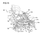
- FIG. 15 is a perspective view showing a state in which the image forming unit 30 is pushed into the carry unit 50 by a predetermined amount from the state in FIG. 14 .
- FIG. 16 is a side view showing a state in which the image forming unit 30 is pushed into the carry unit 50 by a predetermined amount from the state in FIG. 14 .
- FIG. 17 is a perspective view showing a positional relationship between the slide rail 35 and the sheet metal frames 31 a , 31 b of the image forming unit 30 in FIG. 15 and FIG. 16 .
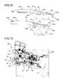
- FIG. 18 is a perspective view showing a state in which a second roller 33 b runs off via a cut-away portion 43 of the second rail portion 35 b.
- FIG. 19 is a side sectional view of the image forming unit 30 and the carry unit 50 in a state in which the second roller 33 b runs off.
- FIG. 20 is a partially enlarged view of a peripheral portion of an engagement protrusion 55 and a lock member 57 in FIG. 19 .
- FIG. 21 is a perspective view showing a state in which the image forming unit 30 is pushed into a predetermined position of the carry unit 50 .
- FIG. 22 is a side view showing a state in which the image forming unit 30 is pushed into a predetermined position of the carry unit 50 .
- FIG. 23 is a side sectional view showing a state in which the image forming unit 30 is pushed into a predetermined position of the carry unit 50 .
- FIG. 1 is a schematic sectional view of an image forming apparatus according an embodiment of the present disclosure
- FIG. 2 is a sectional perspective view of an image forming portion 9 of the image forming apparatus.
- an image forming apparatus 100 here, a monochrome printer
- a paper-sheet supply cassette 2 that stores paper sheets stacked in an apparatus main body lower portion.
- a paper-sheet carry route is formed, which extends substantially horizontally from an apparatus main body front side to an apparatus main body rear side, further extends upward to lead to an ejection tray 19 that is formed on an apparatus main body upper surface, and successively from an upstream along this paper-sheet carry route, a pick-up roller 5 , a pair of paper-sheet supply rollers 6 , an intermediate carry roller 7 , a pair of resist rollers 8 , an image forming portion 9 , a fix portion 10 , and a pair of ejection rollers 11 are disposed. Further, in the image forming apparatus 100 , a control portion (not shown), which controls operation of the above rollers, the image forming portion 9 , the fix portion 10 and the like, is disposed.
- the paper-sheet supply cassette 2 is provided with a paper-sheet stack plate 12 that is supported rotatably with respect to the paper-sheet supply cassette 2 by a rotation pivot 12 a that is disposed at a rear end portion in a paper-sheet carry direction, and paper sheets stacked on the paper-sheet stack plate 12 are pushed to the pick-up roller 5 .
- the pair of paper-sheet supply rollers 6 which include a feed roller 6 a and a retard roller 6 b that comes in tight contact with the feed roller 6 a , are disposed, and in a case where a plurality of paper sheets are supplied at the same time by the pick-up roller 5 , the paper sheets are separated by these feed roller 6 a and the retard roller 6 b , whereby only the uppermost paper sheet is carried at a time.
- the paper sheet separated by the feed roller 6 a and the retard roller 6 b is changed in carry direction by the intermediate carry roller 7 toward a backward portion of the device to be carried to the pair of resist rollers 8 , adjusted in timing by the pair of resist rollers 8 and supplied to the image forming portion 9 .
- the image forming portion 9 forms a predetermined toner image on a paper sheet by means of an electro-photographic process, is composed of a photosensitive drum 14 , that is, an image carrying body supported rotatably counterclockwise by a shaft in FIG. 1 , a charge device 15 , a development device 16 , a cleaning device 17 , a transfer roller 18 disposed to oppose the photosensitive drum 14 via the paper sheet carry route 4 that are disposed around the photosensitive drum 14 and an light exposure unit (LSU) 4 disposed above the photosensitive drum 14 .
- a toner container 20 for supplying toner to the development device 16 is disposed above the development device 16 .
- the photosensitive drum 14 collaborates with the charge device 15 and the cleaning device 17 to constitute a drum unit 21 .
- the drum unit 21 collaborates with the development device 16 and the toner container 20 to constitute an image forming unit 30 that is, as a single body, insertable in and drawable from the image forming apparatus 100 main body.
- the drum unit 21 , the development device 16 and the toner container 20 , which constitute the image forming unit 30 are each separable.
- the intermediate carry roller 7 , the pair of resist rollers 8 and the transfer roller 18 are disposed in a carry unit 50 that is disposed under the image forming unit 30 .
- FIG. 2 shows only a portion of the carry unit 50 .
- the charge device 15 is provided with an electroconductive rubber roller to which a not-shown power supply is connected, and is disposed in such a way that this electroconductive rubber roller contacts the photosensitive drum 14 . And, when the photosensitive drum 14 rotates, the electroconductive rubber roller that contacts with a surface of the photosensitive drum 14 is rotated, and at this time, by applying a predetermined voltage to the electroconductive rubber roller, the surface of the photosensitive drum 14 is evenly charged.
- an electrostatic latent image is formed on the photosensitive drum 14 based on input image data by a laser beam from the light exposure unit 4 , toner is made to adhere to the electrostatic latent image by the development device 16 , whereby a toner image is formed on the surface of the photosensitive drum 14 . Further, the toner image on the surface of the photosensitive drum 14 is transferred by the transfer roller 18 onto a paper sheet that is supplied to a transfer position which is formed at a nip portion between the photosensitive drum 14 and the transfer roller 18 .
- the paper sheet, on which the toner image is transferred is separated from the photosensitive drum 14 and carried to the fix portion 10 .
- This fix portion 10 is disposed in a downstream with respect to the image forming portion 9 in the paper-sheet carry direction, and the paper sheet, onto which the toner image is transferred in the image forming portion 9 , is heated and pressurized by a heat roller and a pressure roller pressurized to the heat roller that are disposed in the fix portion 10 , whereby the toner image transferred on the paper sheet is fixed.
- the paper sheet, on which the image is formed in the image forming portion 9 and the fix portion 10 is ejected onto the ejection tray 19 by the pair of ejection rollers 11 .
- toner remaining on the surface of the photosensitive drum 14 is removed by the cleaning device 17 , and remaining charges on the surface of the photosensitive drum 14 are removed by an electricity removal device (not shown).
- the photosensitive drum 14 is recharged by the charge device 15 , thereafter, images are formed in the same way.
- FIG. 3 and FIG. 4 are perspective views when viewing the image forming unit 30 from an obliquely upper portion and an obliquely lower portion of FIG. 1 , respectively.
- Sheet metal frames 31 a , 31 b are fixed to both side surfaces of the drum unit 21 that constitutes the image forming unit 30 , and a pair of unit-side rollers 33 are rotatably mounted on each of the sheet metal frames 31 a , 31 b.
- the unit-side roller 33 includes a first roller 33 a disposed in a downstream and a second roller 33 b disposed in an upstream in the unit insertion direction, and moves rotating in a rail groove 41 (see FIG. 8 ) formed on an inside of a second rail portion 35 b that constitutes the slide rail 35 (see FIG. 8 ) disposed on the image forming apparatus 100 main body. Because of this, the drum unit 21 is supported slidably along the second rail portion 35 b.
- two rail-side rollers 37 a and 37 b which move in a slide hole 40 formed through a first rail portion 35 a , are rotably mounted.
- a rotation shaft 14 a of the photosensitive drum 14 and a screw bearing 17 a into which a rotation shaft of a collection screw for discharging wasted toner in the cleaning device 17 (see FIG. 1 ) to outside is inserted, protrude.
- the second rail portion 35 b is not shown.
- FIG. 5 is a perspective view showing a state in which the toner container 20 is demounted from the image forming unit 30
- FIG. 6 is a perspective view showing a state in which further the development device 16 is being demounted from the state in FIG. 5
- FIG. 7 is a perspective view of the image forming unit 30 with the toner container 20 and the development device 16 demounted.
- FIG. 5 to FIG. 7 show a state in which the image forming unit 30 is viewed from a front side of FIG. 1 , and the directions of the image forming unit 30 are reverse to each other in FIG. 3 and FIG. 4 .
- the toner container 20 By lifting an upstream end portion of the toner container 20 in the unit insertion direction from the state in FIG. 3 and FIG. 4 , as shown in FIG. 5 , the toner container 20 is demounted from a first housing portion 30 a of the image forming unit 30 . Further, as shown in FIG. 6 , by holding and lifting an upstream end portion (left end portion of FIG. 6 ) of the development device 16 in the unit insertion direction, as shown in FIG. 7 , the development device 16 is demounted from a second housing portion 30 b of the image forming unit 30 . In a front side (front side of FIG. 5 ) of the drum unit 21 , a drum bearing 14 b , into which the rotation shaft 14 a of the photosensitive drum 14 is inserted, protrudes.
- FIG. 8 and FIG. 9 are each a perspective view of the slide rail 35 that slidably supports the image forming unit 30 .
- the slide rail 35 is composed of the first rail portion 35 a and the second rail portion 35 b , and the first rail portion 35 a is fixed to a side frame 25 a (see FIG. 2 ) of the image forming apparatus 100 main body.
- the first rail portion 35 a is provided with the slide hole 40 , while on the outside of the second rail portion 35 b , the rail-side rollers 37 a and 37 b , which slidably engage the slide groove 40 , are disposed.
- the rail-side rollers 37 a , 37 b move in the slide hole 40 , whereby the second rail portion 35 b is selectively disposed at a position to be housed in the first rail portion 35 a as shown in FIG. 8 and a position to be drawn out from the first rail portion 35 a as shown in FIG. 9 .
- a shape of the second rail portion 35 b is a dogleg shape when viewed from side that has a bent portion 38 .
- the rail groove 41 which is interposed between an upper rail 41 a and a lower rail 41 b with which the unit-side rollers 33 a , 33 b of the image forming unit 30 rotatably engage respectively, is formed.
- a portion of the lower rail 41 b is provided with a cut-away portion 43 which is larger than diameters of the unit-side rollers 33 a and 33 b.
- a downstream end portion (right end portion in FIG. 9 ) of the second rail potion 35 b in the unit insertion direction is provided with a first run-off prevention portion 44 a that prevents the unit-side roller 33 a from running off the rail groove 41 .
- an upstream end portion (left end portion in FIG. 9 ) of the second rail portion 35 b is provided with a second run-off prevention portion 44 b that prevents the unit-side roller 33 b from running off the rail groove 41 .
- the second rail portion 35 b in an inner portion of the device is provided with the second run-off prevention portion 44 b by means of a screw that is turned and fitted in the upper rail 41 a .
- the second rail portion 35 b in a front portion of the device is provided with the second run-off prevention portion 44 b by means of a resin snap-fit that is inserted in the rail groove 41 .
- FIG. 10 is a perspective view showing a state in which the image forming unit 30 is drawn out from the image forming apparatus 100 main body
- FIG. 11 is a perspective view showing a relationship between the sheet metal frames 31 a , 31 b and the second rail portion 35 b in FIG. 10 .
- the pair of slide rails 35 which are inclined downward toward a downstream side in the insertion direction, are fixed to the side frame 25 a (see FIG. 2 ) of the image forming apparatus 100 main body.
- a pair of support portions 51 which extend substantially in parallel with the slide rails 35 below the slide rails 35 , are formed on the carry unit 50 that is fixed to the image forming apparatus 100 main body.
- the image forming unit 30 is slidably supported on the image forming apparatus 100 main body by the slide rails 35 and the support portions 51 . Specifically, in the front portion of the apparatus, the drum bearing 14 b contacts the uppermost portion of one of the support portions 51 .
- the screw bearing 17 a contacts the uppermost portion of the other of the support portions 51 .
- the rail-side roller 37 b disposed in the second rail portion 35 b moves to be situated at an upstream end portion (left end in FIG. 10 ) of the slide hole 40 formed through the first rail portion 35 a.
- FIG. 11 shows a state in which the image forming unit 30 is drawn out to the full from the image forming apparatus 100 main body.
- the image forming unit 30 is not completely separated from the image forming apparatus 100 main body, so that a place for leaving the demounted image forming unit 30 becomes unnecessary and there is no risk that when mounting the image forming unit 30 , foreign matter adheres to the image forming unit 30 and brought into the image forming apparatus 100 main body.
- the second rail portion 35 b is bent in the dogleg shape when viewed from side and supported by the first rail portion 35 a in such a way that the upstream side in the insertion direction becomes substantially horizontal, so that the image forming unit 30 is held substantially horizontally with drawn out from the image forming apparatus 100 main body. Accordingly, the height of the image forming unit 30 in a drawn out state is curbed, so that it is possible to widen a view field for an operator during a jam resolving time and a maintenance time. Besides, it is possible to stably hold the image forming unit 30 drawn out from the image forming apparatus 100 main body.
- the unit-side roller 33 (first roller 33 a , second roller 33 b ) rolls in the rail groove 41 of the second rail portion 35 b to move in the insertion direction (arrow A direction). Because of this, as shown in FIG. 13 , the sheet metal frames 31 a and 31 b move to a position near the bent portion 38 of the second rail portion 35 b
- the rail-side rollers 37 a and 37 b of the second rail portion 35 b move in the insertion direction in the slide hole 40 of the first rail portion 35 a .
- the second rail portion 35 b is housed to overlap the first rail portion 35 a , and as shown in FIG. 14 , the image forming unit 30 also is inserted into the inside of the image forming apparatus 100 .
- the image forming unit 30 is further inserted in the arrow A direction, as shown in FIG. 15 and FIG. 16 , the image forming unit 30 is further inserted into the image forming apparatus 100 .
- the first roller 33 a of the unit-side roller 33 goes beyond the bent portion 38 and the cut-away portion 43 and moves in the rail groove 41 of the second rail portion 35 b to the insertion end portion.
- the drum bearing 14 b and the screw bearing 17 a of the image forming unit 30 are supported by the support portion 51 , so that the first roller 33 a does not run off from the cut-away portion 43 .
- the image forming unit 30 also is inclined downward by a predetermined amount, and as shown in FIG. 19 , the photosensitive drum 14 comes close from above the transfer roller 18 .
- the first run-off prevention portion 44 a is formed at the downstream end portion of the second rail portion 35 b in the insertion direction, so that there is no risk that the first roller 33 a runs off from the rail groove 41 of the second rail portion 35 b and the image forming unit 30 falls into the image forming apparatus 100 main body.
- the carry unit 50 is provided with an engagement concave portion 56 into which an engagement protrusion 55 , which protrudes to a position behind the development device 16 , fits.
- a lock member 57 is supported on a side surface of the engagement concave portion 56 to protrude out and go in, and the lock member 57 is biased in the protrusion direction by a coiled spring 60 .
- the engagement protrusion 55 pushes and fits the lock member 57 into the engagement concave portion 56 countering the bias force of the coiled spring 60 .
- FIG. 20 is a partially enlarged view of a peripheral portion of the engagement protrusion 55 and the lock member 57 in FIG. 19 .
- a first inclination surface 55 a is formed on a lower corner portion of the engagement protrusion 55
- a second inclination surface 55 b is formed on an upper corner portion of the engagement protrusion 55 .
- the engagement protrusion 55 is pushed by the lock member 57 , so that the image forming unit 30 is surely fixed to the carry unit 50 .
- the development device 16 is biased toward the photosensitive drum 14 by the lock member 57 (right direction in FIG. 23 ), so that the development device 16 is placed with high accuracy in a predetermined position with respect to the photosensitive drum 14 .
- the coiled spring 60 biases the development device 16 , that is, one of the sub-units, in the predetermined direction, whereby the positioning of the development device 16 (sub-unit) with respect to the image forming unit 30 also becomes possible.
- the rear end portion (left end of FIG. 23 ) of the image forming unit 30 in the insertion direction is held and lifted. Because of this, the second inclination surface 55 b formed on the upper corner portion of the engagement protrusion 55 comes into contact with the lower end portion of the lock member 57 and the arrow X-direction force is exerted onto the lock member 57 , so that the lock member 57 moves in the arrow X direction countering the bias force of the coiled spring 60 .
- the engagement between the engagement protrusion 55 and the lock member 57 is released, whereby the second roller 33 b is inserted into the rail groove 41 from the cut-away portion 43 of the second rail portion 35 b.
- the unit-side rollers 33 a and 33 b move rolling in the rail groove 41 of the second rail portion 35 b , the rail-side rollers 37 a and 37 b of the second rail portion 35 b slide in the slide hole 40 of the first rail portion 35 a , and the image forming unit 30 is drawn out to the position shown in FIG. 10 .
- the second roller 33 b run off from the cut-away portion 43 of the second rail portion 35 b , it is possible to make the photosensitive drum 14 come close to the transfer roller 18 from right over. Accordingly, it is possible to smoothly mount and demount the image forming unit 30 along the slide rail 35 avoiding contact with obstacles such as the pair of resist rollers 8 , a before-transfer guide 61 , a roller hold portion 63 (see FIG. 23 ) for manual paper-sheet supply and the like which are present below the mount-demount routes of the image forming unit 30 , and the photosensitive drum 14 .
- the support portion 51 that supports the image forming unit 30 by disposing, on the image forming apparatus 100 main body, the support portion 51 that supports the image forming unit 30 , it is possible to prevent the first roller 33 a in the downstream in the insertion direction from running off when passing the cut-away portion 43 and surely make only the second roller 33 b in the upstream in the insertion direction run off.
- the image forming unit 30 by fixing the image forming unit 30 to the carry unit 50 by means of the engagement between the engagement protrusion 55 and the lock member 57 , it is possible to place the image forming unit 30 in the predetermined position with high accuracy.
- the development device 16 is pushed toward the photosensitive drum 14 by the bias force of the coiled spring 60 that biases the lock member 57 , so that it is also possible to easily and surely perform the positioning of the photosensitive drum 14 and the development device 16 .
- the first inclination surface 55 a and the second inclination surface 55 b are formed on the engagement protrusion 55 , however, the inclination surface may be formed on the lock member 57 .
- the lock member 57 is pushed along the inclination surface to move in a direction to be released from the engagement during the mount-demount time of the image forming unit 30 . Because of this, the operator is able to surely lock the image forming unit 30 by only pushing it into the image forming apparatus 100 main body, and able to unlock the image forming unit 30 by only lifting it from the image forming apparatus 100 main body.
- the present disclosure is not limited to the above embodiment, and variously modifiable without departing from the spirit of the present disclosure.
- the structure is employed, in which the second roller 33 b of the unit-side roller 33 in the upstream in the insertion direction is made to run off from the cut-away portion 43 so as to position the image forming unit 30 , however, it is also possible to form the cut-away portion 43 near the tip end portion of the lower rail 41 b of the second rail portion 35 b in the insertion direction so as to make the first roller 33 a in the downstream in the insertion direction run off.
- a structure may be employed, in which the cut-away portion 43 is formed near the tip end portion of the upper rail 41 a of the second rail portion 35 b in the insertion direction and by lifting the downstream side of the image forming unit 30 in the insertion direction, the first roller 33 a in the downstream in the unit insertion direction is made to run off upward. In this case, it is possible to place the image forming unit 30 in the predetermined position avoiding the obstacles present above the mount-demount routes of the image forming unit 30 .
- either of the first roller 33 a and the second roller 33 b of the unit-side roller 33 is made to run off via the cut-away portion 43 , whereby the image forming unit 30 is positioned, so that it is possible to avoid contact with the obstacles present above the mount-demount routes during the time the image forming unit 30 is mounted and demounted along the slide rail 35 .
- the mount-demount mechanism for the image forming unit 30 which is mounted on and demounted form the carry unit 50 , is described as an example, however, it goes without saying that the present disclosure is also applicable to a mount-demount mechanism for other units such as the intermediate transfer unit, the fix unit and the like that are mounted and demounted with disposed on the slide rail 35 .
- the slide rail 35 has the expandable and contractable structure that includes the first rail portion 35 a and the second rail portion 35 b , however, the slide rail 35 may slidably connect three or more rail portions to each other or may be structured by only one rail portion that does not expand nor contract.
- the present disclosure is not limited to the monochrome printer shown in FIG. 1 and is applicable to various image forming apparatuses that include units such as a monochrome copy machine, a digital multi-function machine, a color copy machine, a color printer, a facsimile and the like that are mountable on and demountable from the device main body via a slide rail.
- the present disclosure is usable for an insertion and drawing out mechanism for a unit that is mountable on and demountable from an image forming apparatus main body.
- a mount-demount mechanism is obtained, in which it is possible to perform the insertion and drawing out operations of a target unit avoiding other units and components that are obstacles and to dispose the unit in a predetermined position of the image forming apparatus main body with high accuracy.
Landscapes
- Engineering & Computer Science (AREA)
- Computer Vision & Pattern Recognition (AREA)
- Physics & Mathematics (AREA)
- General Physics & Mathematics (AREA)
- Electrophotography Configuration And Component (AREA)
Applications Claiming Priority (2)
| Application Number | Priority Date | Filing Date | Title |
|---|---|---|---|
| JP2011099036A JP5417373B2 (ja) | 2011-04-27 | 2011-04-27 | ユニット着脱機構及びそれを備えた画像形成装置 |
| JP2011-099036 | 2011-04-27 |
Publications (2)
| Publication Number | Publication Date |
|---|---|
| US20120275820A1 US20120275820A1 (en) | 2012-11-01 |
| US8824920B2 true US8824920B2 (en) | 2014-09-02 |
Family
ID=47054363
Family Applications (1)
| Application Number | Title | Priority Date | Filing Date |
|---|---|---|---|
| US13/454,175 Active 2032-10-15 US8824920B2 (en) | 2011-04-27 | 2012-04-24 | Unit mount-demount mechanism and image forming apparatus including the same |
Country Status (3)
| Country | Link |
|---|---|
| US (1) | US8824920B2 (ja) |
| JP (1) | JP5417373B2 (ja) |
| CN (1) | CN102759878B (ja) |
Cited By (2)
| Publication number | Priority date | Publication date | Assignee | Title |
|---|---|---|---|---|
| US9804556B2 (en) | 2015-08-26 | 2017-10-31 | Kyocera Document Solutions Inc. | Image forming apparatus that facilitates positioning and attachment/detachment of image forming unit |
| US20180203395A1 (en) * | 2015-07-14 | 2018-07-19 | S-Printing Solution Co., Ltd. | Automatic mounting apparatus and image forming apparatus including same |
Families Citing this family (9)
| Publication number | Priority date | Publication date | Assignee | Title |
|---|---|---|---|---|
| JP5934676B2 (ja) * | 2013-05-30 | 2016-06-15 | 京セラドキュメントソリューションズ株式会社 | 画像形成装置 |
| JP2016206523A (ja) * | 2015-04-27 | 2016-12-08 | 京セラドキュメントソリューションズ株式会社 | 現像剤収容容器を備えた画像形成装置、画像形成装置に装着される現像剤収容容器 |
| JP6311682B2 (ja) | 2015-09-10 | 2018-04-18 | 京セラドキュメントソリューションズ株式会社 | 画像形成装置 |
| JP6390563B2 (ja) | 2015-09-10 | 2018-09-19 | 京セラドキュメントソリューションズ株式会社 | 画像形成装置 |
| JP6390564B2 (ja) | 2015-09-11 | 2018-09-19 | 京セラドキュメントソリューションズ株式会社 | 画像形成装置 |
| JP6428674B2 (ja) | 2016-02-18 | 2018-11-28 | 京セラドキュメントソリューションズ株式会社 | シート搬送装置及びそれを備えた画像形成装置 |
| JP6520811B2 (ja) | 2016-04-28 | 2019-05-29 | 京セラドキュメントソリューションズ株式会社 | ユニット着脱機構及びそれを備えた画像形成装置 |
| US10012950B2 (en) | 2016-09-05 | 2018-07-03 | Kyocera Document Solutions Inc. | Image forming apparatus |
| JP7306214B2 (ja) | 2019-10-21 | 2023-07-11 | 沖電気工業株式会社 | 画像形成装置 |
Citations (8)
| Publication number | Priority date | Publication date | Assignee | Title |
|---|---|---|---|---|
| JPH0816069A (ja) | 1994-04-28 | 1996-01-19 | Canon Inc | プロセスカートリッジ及び画像形成装置 |
| JP2003066718A (ja) | 2001-08-24 | 2003-03-05 | Hitachi Koki Co Ltd | 電子写真装置の現像装置 |
| US20030049046A1 (en) | 2001-09-13 | 2003-03-13 | Brother Kogyo Kabushiki Kaisha | Image forming device and process unit for use therein |
| US20060091769A1 (en) * | 2002-12-18 | 2006-05-04 | William Dubon | Telescoping slide rail with latching and alignment mechanisms |
| JP2007034335A (ja) | 2006-10-30 | 2007-02-08 | Ricoh Co Ltd | ユニット操作装置および画像形成装置 |
| US20070201900A1 (en) | 2006-02-28 | 2007-08-30 | Brother Kogyo Kabushiki Kaisha | Image forming apparatus and image carrier unit |
| JP2009157389A (ja) | 2009-02-23 | 2009-07-16 | Canon Inc | プロセスカートリッジ及び電子写真画像形成装置 |
| US8660454B2 (en) * | 2010-12-09 | 2014-02-25 | Samsung Electronics Co., Ltd. | Image forming apparatus with developing unit drawer |
Family Cites Families (4)
| Publication number | Priority date | Publication date | Assignee | Title |
|---|---|---|---|---|
| JP2582159B2 (ja) * | 1989-06-30 | 1997-02-19 | 三田工業株式会社 | 現像装置 |
| JP3687397B2 (ja) * | 1999-03-04 | 2005-08-24 | セイコーエプソン株式会社 | 画像形成装置 |
| JP2009157289A (ja) * | 2007-12-28 | 2009-07-16 | Fujitsu Ltd | 色度調整機能を備えた情報処理装置及び該情報処理装置の表示制御方法 |
| JP5349999B2 (ja) * | 2009-02-16 | 2013-11-20 | キヤノン株式会社 | プロセスカートリッジおよび画像形成装置 |
-
2011
- 2011-04-27 JP JP2011099036A patent/JP5417373B2/ja active Active
-
2012
- 2012-04-24 US US13/454,175 patent/US8824920B2/en active Active
- 2012-04-27 CN CN201210132586.8A patent/CN102759878B/zh active Active
Patent Citations (10)
| Publication number | Priority date | Publication date | Assignee | Title |
|---|---|---|---|---|
| JPH0816069A (ja) | 1994-04-28 | 1996-01-19 | Canon Inc | プロセスカートリッジ及び画像形成装置 |
| US5937240A (en) | 1994-04-28 | 1999-08-10 | Canon Kabushiki Kaisha | Process cartridge having positioning members and image forming apparatus using such a process cartridge |
| JP2003066718A (ja) | 2001-08-24 | 2003-03-05 | Hitachi Koki Co Ltd | 電子写真装置の現像装置 |
| US20030049046A1 (en) | 2001-09-13 | 2003-03-13 | Brother Kogyo Kabushiki Kaisha | Image forming device and process unit for use therein |
| US20060091769A1 (en) * | 2002-12-18 | 2006-05-04 | William Dubon | Telescoping slide rail with latching and alignment mechanisms |
| US20070201900A1 (en) | 2006-02-28 | 2007-08-30 | Brother Kogyo Kabushiki Kaisha | Image forming apparatus and image carrier unit |
| JP2007232933A (ja) | 2006-02-28 | 2007-09-13 | Brother Ind Ltd | 画像形成装置、及び像担持体ユニット |
| JP2007034335A (ja) | 2006-10-30 | 2007-02-08 | Ricoh Co Ltd | ユニット操作装置および画像形成装置 |
| JP2009157389A (ja) | 2009-02-23 | 2009-07-16 | Canon Inc | プロセスカートリッジ及び電子写真画像形成装置 |
| US8660454B2 (en) * | 2010-12-09 | 2014-02-25 | Samsung Electronics Co., Ltd. | Image forming apparatus with developing unit drawer |
Non-Patent Citations (1)
| Title |
|---|
| Machine translation of Tetsuo, JP 2007-034335 A, publication date: Feb. 8, 2007. * |
Cited By (3)
| Publication number | Priority date | Publication date | Assignee | Title |
|---|---|---|---|---|
| US20180203395A1 (en) * | 2015-07-14 | 2018-07-19 | S-Printing Solution Co., Ltd. | Automatic mounting apparatus and image forming apparatus including same |
| US10768567B2 (en) * | 2015-07-14 | 2020-09-08 | Hewlett-Packard Development Company, L.P. | Automatic mounting apparatus and image forming apparatus including same |
| US9804556B2 (en) | 2015-08-26 | 2017-10-31 | Kyocera Document Solutions Inc. | Image forming apparatus that facilitates positioning and attachment/detachment of image forming unit |
Also Published As
| Publication number | Publication date |
|---|---|
| CN102759878A (zh) | 2012-10-31 |
| CN102759878B (zh) | 2015-05-20 |
| JP5417373B2 (ja) | 2014-02-12 |
| US20120275820A1 (en) | 2012-11-01 |
| JP2012230280A (ja) | 2012-11-22 |
Similar Documents
| Publication | Publication Date | Title |
|---|---|---|
| US8824920B2 (en) | Unit mount-demount mechanism and image forming apparatus including the same | |
| JP4974290B2 (ja) | 画像形成装置 | |
| JP4412258B2 (ja) | 画像形成装置 | |
| US20010051059A1 (en) | Image forming apparatus | |
| US9417604B2 (en) | Image forming apparatus | |
| US9134686B2 (en) | Image forming apparatus provided with movable conveying unit | |
| JP2009157209A (ja) | 画像形成装置 | |
| JP2012226002A (ja) | 画像形成装置 | |
| US8798496B2 (en) | Electro-photographic type image forming device and photosensitive unit provided in the same | |
| US8903271B2 (en) | Image forming apparatus provided with a photosensitve drum and a static eliminator in a fixed position in the apparatus facing the photosensitive drum | |
| JP4184132B2 (ja) | 画像形成装置 | |
| US20110280617A1 (en) | Image Formation Apparatus | |
| US9637331B2 (en) | Image forming apparatus | |
| JP4968352B2 (ja) | 画像形成装置 | |
| JP2009115836A (ja) | 画像形成装置 | |
| US9025995B2 (en) | Image forming apparatus having belt cleaning unit and waste toner cartridge connectable to each other | |
| JP2007171848A (ja) | 画像形成装置 | |
| US9304482B2 (en) | Image forming apparatus with detachable components | |
| US20190196392A1 (en) | Image forming apparatus | |
| JP5523009B2 (ja) | 画像形成装置 | |
| JP3666587B2 (ja) | 画像形成装置 | |
| JPH0553378A (ja) | 電子写真装置 | |
| CN103853022B (zh) | 成像装置 | |
| JP2012037914A (ja) | 画像形成装置 | |
| US10845737B2 (en) | Image forming apparatus and transfer device |
Legal Events
| Date | Code | Title | Description |
|---|---|---|---|
| AS | Assignment |
Owner name: KYOCERA DOCUMENT SOLUTIONS INC., JAPAN Free format text: ASSIGNMENT OF ASSIGNORS INTEREST;ASSIGNOR:ETO, DAISUKE;REEL/FRAME:028095/0269 Effective date: 20120417 |
|
| STCF | Information on status: patent grant |
Free format text: PATENTED CASE |
|
| FEPP | Fee payment procedure |
Free format text: PAYOR NUMBER ASSIGNED (ORIGINAL EVENT CODE: ASPN); ENTITY STATUS OF PATENT OWNER: LARGE ENTITY |
|
| MAFP | Maintenance fee payment |
Free format text: PAYMENT OF MAINTENANCE FEE, 4TH YEAR, LARGE ENTITY (ORIGINAL EVENT CODE: M1551) Year of fee payment: 4 |
|
| MAFP | Maintenance fee payment |
Free format text: PAYMENT OF MAINTENANCE FEE, 8TH YEAR, LARGE ENTITY (ORIGINAL EVENT CODE: M1552); ENTITY STATUS OF PATENT OWNER: LARGE ENTITY Year of fee payment: 8 |