US8804375B2 - PWM-PSM controlled power supply with auxiliary switching circuit for soft-switching - Google Patents
PWM-PSM controlled power supply with auxiliary switching circuit for soft-switching Download PDFInfo
- Publication number
- US8804375B2 US8804375B2 US13/306,398 US201113306398A US8804375B2 US 8804375 B2 US8804375 B2 US 8804375B2 US 201113306398 A US201113306398 A US 201113306398A US 8804375 B2 US8804375 B2 US 8804375B2
- Authority
- US
- United States
- Prior art keywords
- control
- switching
- auxiliary
- phase
- power
- Prior art date
- Legal status (The legal status is an assumption and is not a legal conclusion. Google has not performed a legal analysis and makes no representation as to the accuracy of the status listed.)
- Active, expires
Links
Images




Classifications
-
- H—ELECTRICITY
- H02—GENERATION; CONVERSION OR DISTRIBUTION OF ELECTRIC POWER
- H02M—APPARATUS FOR CONVERSION BETWEEN AC AND AC, BETWEEN AC AND DC, OR BETWEEN DC AND DC, AND FOR USE WITH MAINS OR SIMILAR POWER SUPPLY SYSTEMS; CONVERSION OF DC OR AC INPUT POWER INTO SURGE OUTPUT POWER; CONTROL OR REGULATION THEREOF
- H02M3/00—Conversion of DC power input into DC power output
- H02M3/22—Conversion of DC power input into DC power output with intermediate conversion into AC
- H02M3/24—Conversion of DC power input into DC power output with intermediate conversion into AC by static converters
- H02M3/28—Conversion of DC power input into DC power output with intermediate conversion into AC by static converters using discharge tubes with control electrode or semiconductor devices with control electrode to produce the intermediate AC
- H02M3/325—Conversion of DC power input into DC power output with intermediate conversion into AC by static converters using discharge tubes with control electrode or semiconductor devices with control electrode to produce the intermediate AC using devices of a triode or a transistor type requiring continuous application of a control signal
- H02M3/335—Conversion of DC power input into DC power output with intermediate conversion into AC by static converters using discharge tubes with control electrode or semiconductor devices with control electrode to produce the intermediate AC using devices of a triode or a transistor type requiring continuous application of a control signal using semiconductor devices only
- H02M3/337—Conversion of DC power input into DC power output with intermediate conversion into AC by static converters using discharge tubes with control electrode or semiconductor devices with control electrode to produce the intermediate AC using devices of a triode or a transistor type requiring continuous application of a control signal using semiconductor devices only in push-pull configuration
- H02M3/3376—Conversion of DC power input into DC power output with intermediate conversion into AC by static converters using discharge tubes with control electrode or semiconductor devices with control electrode to produce the intermediate AC using devices of a triode or a transistor type requiring continuous application of a control signal using semiconductor devices only in push-pull configuration with automatic control of output voltage or current
- H02M3/3378—Conversion of DC power input into DC power output with intermediate conversion into AC by static converters using discharge tubes with control electrode or semiconductor devices with control electrode to produce the intermediate AC using devices of a triode or a transistor type requiring continuous application of a control signal using semiconductor devices only in push-pull configuration with automatic control of output voltage or current in a push-pull configuration of the parallel type
-
- H—ELECTRICITY
- H02—GENERATION; CONVERSION OR DISTRIBUTION OF ELECTRIC POWER
- H02M—APPARATUS FOR CONVERSION BETWEEN AC AND AC, BETWEEN AC AND DC, OR BETWEEN DC AND DC, AND FOR USE WITH MAINS OR SIMILAR POWER SUPPLY SYSTEMS; CONVERSION OF DC OR AC INPUT POWER INTO SURGE OUTPUT POWER; CONTROL OR REGULATION THEREOF
- H02M7/00—Conversion of AC power input into DC power output; Conversion of DC power input into AC power output
- H02M7/42—Conversion of DC power input into AC power output without possibility of reversal
- H02M7/44—Conversion of DC power input into AC power output without possibility of reversal by static converters
- H02M7/48—Conversion of DC power input into AC power output without possibility of reversal by static converters using discharge tubes with control electrode or semiconductor devices with control electrode
- H02M7/53—Conversion of DC power input into AC power output without possibility of reversal by static converters using discharge tubes with control electrode or semiconductor devices with control electrode using devices of a triode or transistor type requiring continuous application of a control signal
- H02M7/537—Conversion of DC power input into AC power output without possibility of reversal by static converters using discharge tubes with control electrode or semiconductor devices with control electrode using devices of a triode or transistor type requiring continuous application of a control signal using semiconductor devices only, e.g. single switched pulse inverters
- H02M7/5387—Conversion of DC power input into AC power output without possibility of reversal by static converters using discharge tubes with control electrode or semiconductor devices with control electrode using devices of a triode or transistor type requiring continuous application of a control signal using semiconductor devices only, e.g. single switched pulse inverters in a bridge configuration
- H02M7/53871—Conversion of DC power input into AC power output without possibility of reversal by static converters using discharge tubes with control electrode or semiconductor devices with control electrode using devices of a triode or transistor type requiring continuous application of a control signal using semiconductor devices only, e.g. single switched pulse inverters in a bridge configuration with automatic control of output voltage or current
- H02M7/53878—Conversion of DC power input into AC power output without possibility of reversal by static converters using discharge tubes with control electrode or semiconductor devices with control electrode using devices of a triode or transistor type requiring continuous application of a control signal using semiconductor devices only, e.g. single switched pulse inverters in a bridge configuration with automatic control of output voltage or current by time shifting switching signals of one diagonal pair of the bridge with respect to the other diagonal pair
-
- H—ELECTRICITY
- H02—GENERATION; CONVERSION OR DISTRIBUTION OF ELECTRIC POWER
- H02M—APPARATUS FOR CONVERSION BETWEEN AC AND AC, BETWEEN AC AND DC, OR BETWEEN DC AND DC, AND FOR USE WITH MAINS OR SIMILAR POWER SUPPLY SYSTEMS; CONVERSION OF DC OR AC INPUT POWER INTO SURGE OUTPUT POWER; CONTROL OR REGULATION THEREOF
- H02M1/00—Details of apparatus for conversion
- H02M1/0003—Details of control, feedback or regulation circuits
- H02M1/0032—Control circuits allowing low power mode operation, e.g. in standby mode
-
- H—ELECTRICITY
- H02—GENERATION; CONVERSION OR DISTRIBUTION OF ELECTRIC POWER
- H02M—APPARATUS FOR CONVERSION BETWEEN AC AND AC, BETWEEN AC AND DC, OR BETWEEN DC AND DC, AND FOR USE WITH MAINS OR SIMILAR POWER SUPPLY SYSTEMS; CONVERSION OF DC OR AC INPUT POWER INTO SURGE OUTPUT POWER; CONTROL OR REGULATION THEREOF
- H02M1/00—Details of apparatus for conversion
- H02M1/0048—Circuits or arrangements for reducing losses
- H02M1/0054—Transistor switching losses
- H02M1/0058—Transistor switching losses by employing soft switching techniques, i.e. commutation of transistors when applied voltage is zero or when current flow is zero
-
- H02M2001/0032—
-
- H02M2001/0058—
-
- H02M2007/53878—
-
- Y—GENERAL TAGGING OF NEW TECHNOLOGICAL DEVELOPMENTS; GENERAL TAGGING OF CROSS-SECTIONAL TECHNOLOGIES SPANNING OVER SEVERAL SECTIONS OF THE IPC; TECHNICAL SUBJECTS COVERED BY FORMER USPC CROSS-REFERENCE ART COLLECTIONS [XRACs] AND DIGESTS
- Y02—TECHNOLOGIES OR APPLICATIONS FOR MITIGATION OR ADAPTATION AGAINST CLIMATE CHANGE
- Y02B—CLIMATE CHANGE MITIGATION TECHNOLOGIES RELATED TO BUILDINGS, e.g. HOUSING, HOUSE APPLIANCES OR RELATED END-USER APPLICATIONS
- Y02B70/00—Technologies for an efficient end-user side electric power management and consumption
- Y02B70/10—Technologies improving the efficiency by using switched-mode power supplies [SMPS], i.e. efficient power electronics conversion e.g. power factor correction or reduction of losses in power supplies or efficient standby modes
-
- Y02B70/1491—
-
- Y02B70/16—
Definitions
- the present invention relates to a power supply and an arc processing power supply including an inverter circuit that converts DC power into predetermined high frequency AC power.
- a power supply for an arc processing machine or the like generates DC power from input AC power and converts the DC power to high frequency AC power by performing a switching operation with an inverter circuit.
- the power supply uses a welding transformer to adjust the voltage of the high frequency AC power.
- a downstream circuit converts the voltage-adjusted high frequency AC power to DC output power that is suitable for arc welding or the like.
- the output voltage is adjusted by controlling the switching operation of the inverter circuit.
- Japanese Laid-Open Patent Publication No. 2006-280120 describes an example of a power supply including an inverter circuit configured by two pairs of switching elements. Two control pulse signals are provided to the two pair of switching elements so that the pairs of switching elements are alternately activated and deactivated. Phase shift modulation (PSM) control is performed so that the phase of the control pulse signal provided to the first pair of switching elements is shifted from the phase of the control pulse signal provided to the second pair of switching elements. More specifically, the phase difference between the control pulse signal provided to the first pair and the control pulse signal provided to the second pair is controlled (ON pulse width is fixed) to adjust the time during which corresponding switching elements of the first and second pairs are simultaneously activated. This adjusts the average voltage of the high frequency AC power output from the inverter circuit. In other words, the output voltage of the power supply is adjusted.
- PSM Phase shift modulation
- the power supply includes a rectification-smoothing circuit that converts input AC power to DC power.
- An auxiliary switching element is arranged along a power line between the rectification-smoothing circuit and the inverter circuit. Activation and deactivation of the auxiliary switching element is performed in cooperation with the switching elements of the inverter circuits, and charging and discharging of the auxiliary capacitor is performed accordingly. This is referred to as soft switching control and reduces switching losses in the auxiliary switching element and the inverter circuit switching elements.
- the two control pulse signals have a large phase difference and a sufficiently wide ON pulse width.
- the pulse width is fixed so that the maximum output can be generated. This ensures activation of the switching elements and avoids the problems of unstable output or biased magnetization.
- the ON pulse width is set to be sufficiently wide so that the maximum output can be generated
- the activated time of the other one of the two switching elements becomes long.
- the activation time of the other switching element becomes long. This lengthens the time during which return current is produced in the inverter circuit. Conduction loss caused by the return current is increased. Thus, power is not efficiently used.
- An inverter circuit includes two pairs of switching elements connected between the first power line and the second power line.
- the inverter circuit performs a switching operation that alternately activates and deactivates the two pairs of switching elements, and the inverter circuit converts input DC power to high frequency AC power.
- An auxiliary switching circuit includes an auxiliary switching element and an auxiliary capacitor. The auxiliary switching element is operated in cooperation with the switching operation of the inverter circuit.
- the auxiliary switching element includes a first terminal connected to the first power line and a second terminal that receives the DC power.
- the auxiliary capacitor is connected between the first terminal of the auxiliary switching element and the second power line.
- the power supply performs output control, which controls the switching operation of the inverter circuit to adjust output power that is supplied to a load, and soft switching control, which deactivates the auxiliary switching element before the two pairs of switching elements to reduce switching loss of the two pairs of switching elements.
- a pulse width modulation control unit adjusts ON pulse widths of two pairs of control signals respectively provided to the two pairs of switching elements and adjusts an ON pulse width of an auxiliary control pulse signal provided to the auxiliary switching element in accordance with the two pairs of control pulse signals.
- a phase shift control unit adjusts a phase difference of the control pulse signals in each pair provided to the two pairs of switching elements or adjusts a phase difference of the two pairs of control pulse signals and the auxiliary control pulse signal.
- a control switching unit selectively switches the pulse width modulation control unit and the phase shift control unit so that the pulse width modulation control unit operates when a relatively large output power is required and the phase shift control means operates when a relatively small output power is required.
- FIG. 1 is a circuit diagram of an arc processing power supply according to a first exemplary embodiment of the present invention
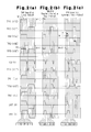
- FIGS. 2( a ) to 2 ( c ) are voltage-current waveform charts for different parts of the power supply of the first exemplary embodiment, in which FIG. 2( a ) is a chart for a PWM operation (maximum output), FIG. 2( b ) is a chart for a PWM-PSM boundary operation (small output), and FIG. 2( c ) is for a PSM operation (extremely small output);
- FIG. 3 is a chart illustrating PWM-PSM control in the first exemplary embodiment
- FIGS. 4( a ) to 4 ( c ) are voltage-current waveform charts for different parts of a power supply according to a second exemplary embodiment of the present invention, in which FIG. 4( a ) is a chart for a PWM operation (maximum output), FIG. 4( b ) is a chart for a PWM-PSM boundary operation (small output), and FIG. 4( c ) is for a PSM operation (extremely small output);
- FIGS. 5( a ) to 5 ( c ) are voltage-current waveform charts for different parts of a power supply according to a third exemplary embodiment of the present invention, in which FIG. 5( a ) is a chart for a PWM operation (maximum output), FIG. 5( b ) is a chart for a PWM-PSM boundary operation (small output), and FIG. 5( c ) is for a PSM operation (extremely small output); and
- FIGS. 6( a ) to 6 ( c ) are voltage-current waveform charts for different parts of a power supply according to a fourth exemplary embodiment of the present invention, in which FIG. 6( a ) is a chart for a PWM operation (maximum output), FIG. 6( b ) is a chart for a PWM-PSM boundary operation (small output), and FIG. 6( c ) is for a PSM operation (extremely small output).
- the arc processing machine includes an arc processing power supply 11 that generates output voltage, which is supplied to a torch TH. This generates an arc directed from the torch TH to a processing subject M to perform arc processing, such as arc welding or arc cutting, on the processing subject M.
- arc processing such as arc welding or arc cutting
- the power supply 11 includes a DC conversion circuit 12 , an inverter circuit 13 , an auxiliary switching circuit 14 , a transformer INT, and an output conversion circuit 15 .
- the DC conversion circuit 12 includes a rectification circuit DR 1 , which is formed by a diode bridge, and a smoothing current Cl.
- the DC conversion circuit 12 converts three-phase input AC power, which is supplied from a commercial power supply, to DC power. Further, the DC conversion circuit 12 supplies the converted DC power to the inverter circuit 13 via two power lines L 1 and L 2 .
- the inverter circuit 13 is formed by a bridge circuit including two switching elements TR 1 and TR 2 , such as insulated gate bipolar transistors (IGBTs), arranged closer to the power line L 1 , and two switching elements TR 3 and TR 4 , such as IGBTs, arranged closer to the power line L 2 . Freewheeling diodes D 1 to D 4 are reversely connected to the switching elements TR 1 to TR 4 , respectively.
- the gates of the switching elements TR 1 to TR 4 are provided with control pulse signals from a control circuit 21 .
- the switching elements TR 1 and TR 4 form one set, and the switching elements TR 2 and TR 3 form another set.
- the two sets are alternately activated and deactivated.
- the activation and deactivation results in the switching elements TR 1 to TR 4 converting the input DC power to high frequency AC power.
- the converted high-frequency AC power is supplied to the transformer.
- the auxiliary switching circuit 14 is arranged between the inverter circuit 13 and the DC conversion circuit 12 and includes a switching element TR 5 , such as an IGBT, an auxiliary capacitor C 2 , and a freewheeling diode D 5 .
- the freewheeling diode D 5 is reverse-connected to the switching element TR 5 .
- the switching element TR 5 and the freewheeling diode D 5 are arranged on the power line L 2 at the downstream side of the DC conversion circuit 12 .
- the auxiliary capacitor C 2 is arranged between the downstream side of the switching element TR 5 and the inverter circuit 13 and connected to the power lines L 1 and L 2 .
- the gate of the switching element TR 5 receives a control pulse signal from the control circuit 21 .
- the switching element TR 5 is activated and deactivated in cooperation with the switching elements TR 1 to TR 4 of the inverter circuit 13 . As a result, soft switching is performed thereby reducing switching losses in the switching elements TR 1 to TR 4 of the inverter circuit 13 and in the switching element TR 5 .
- the transformer INT includes a primary coil and a secondary coil.
- the primary coil of the transformer INT is supplied with high frequency AC power from the switching elements TR 1 to TR 4 .
- the transformer INT adjusts the voltage of the high frequency AC power and supplies high frequency AC power that has been adjusted to a predetermined voltage from its secondary coil to the output conversion circuit 15 .
- the output conversion circuit 15 includes a rectification circuit DR 2 and a DC reactor DCL.
- the rectification circuit DR 2 includes two diodes. The anodes of the two diodes are respectively connected to the two ends of the secondary coil in the transformer INT. The cathodes of the diodes are connected to the DC reactor DCL.
- the DC reactor DCL is arranged on an output line L 3 .
- An output line L 4 is connected to an intermediate point of the secondary coil in the transformer INT.
- the output conversion circuit 15 converts the high frequency AC power from the transformer INT to DC output power, which is suitable for arc processing, with the rectification circuit DR 2 and the DC reactor DCL.
- the torch TH is connected to the output line L 3
- the processing subject M is connected to the output line L 4 .
- the output power supplied to the torch TH through the output line L 3 generates an arc between the torch TH and the processing subject M to perform arc processing, such as arc welding or arc cutting, on the processing subject M.
- the control circuit 21 controls the switching of the inverter circuit 13 to adjust the output power.
- the control circuit 21 performs switching control in which the inverter circuit 13 cooperates with the auxiliary switching circuit 14 . More specifically, the power supply 11 includes a detection sensor (not shown) that detects the actual values of the present output voltage and output current. Based on the detection value (actual value) of the detection sensor, the control circuit 21 performs switching control to obtain an output voltage that is suitable for the present state.
- the control circuit 21 includes a difference calculation unit 22 , a control switching unit 23 , a pulse width calculation unit 24 , and a phase difference calculation unit 25 .
- the difference calculation unit 22 of the control circuit 21 calculates a difference X between the present target value and actual value.
- the control switching unit 23 of the control circuit 21 determines a switching control method for the inverter circuit 13 . More specifically, when the calculated difference X is greater than a predetermined value (Xa), the control switching unit 23 performs pulse width modulation (PWM) control in the inverter circuit 13 . When a small output voltage or a large output voltage is required by the power supply 11 , the control switching unit 23 performs pulse width modulation (PWM) control. Based on the calculated difference X from the actual value, the pulse width calculation unit 24 of the control circuit 21 calculates an ON pulse width Wm of the switching elements TR 1 to TR 4 in the inverter circuit 13 .
- PWM pulse width modulation
- the pulse width calculation unit calculates an ON pulse width Ws of the switching element TR 5 in the auxiliary switching circuit 14 .
- the ON pulse widths Wm and Ws are set to be wide.
- the ON pulse widths Wm and Ws are set to be narrow.
- the ON pulse widths Wm and Ws are respectively set to minimum pulse widths Wm 0 and Ws 0 , which are predetermined narrow pulse widths.
- the switching elements TR 1 and TR 4 of one set are simultaneously activated and deactivated, and the switching elements TR 2 and R 3 of the other set are simultaneously activated and deactivated. More specifically, during PWM control, the control circuit 21 provides each of the set of the switching elements TR 1 and TR 4 and the set of the switching elements TR 2 and TR 3 with two control pulse signals having the same ON pulse switch Wm and no phase difference. Further, the switching element TR 5 of the auxiliary switching circuit 14 is simultaneously activated with the switching elements TR 1 and TR 4 and the switching elements TR 2 and TR 3 . The switching element TR 5 is deactivated before the switching elements TR 1 to TR 4 .
- the control circuit 21 sets the ON pulse width Ws for the switching element TR 5 to be narrower than the ON pulse width Wm for the switching elements TR 1 to TR 4 so that the rising edge of the ON pulse for the switching element TR 5 conforms with the rising edge of each ON pulse for the switching elements TR 1 to TR 4 and so that the falling edge of the ON pulse for the switching element TR 5 is earlier by a predetermined time than the falling edge of each ON pulse for the switching elements TR 1 to TR 4 (so that discharging of the auxiliary capacitor C 2 is sufficiently or completely performed).
- a control signal having a narrow ON pulse width is set particularly for the switching element TR 5 of the auxiliary switching circuit 14 .
- the switching element TR 5 may not be sufficiently activated.
- the ON pulse width Ws of the control signal is set to the minimum pulse width Ws 0 , which is the lower limit allowing for sufficient activation of the switching element TR 5 and he ON pulse width Wm of the control signal is set to the minimum pulse width Wm 0 , which is the lower limit allowing for sufficient activation of the switching elements TR 1 to TR 4 .
- the control switching unit 23 of the control circuit 21 switches the switching control of the inverter circuit 13 from PWM control to phase shift modulation (PSM) control.
- PWM phase shift modulation
- the phase of a control pulse signal provided to one of the switching elements in each set is referred to as a reference phase
- the phase of a control pulse signal provided to the other one of the switching elements in each set is referred to as a control phase.
- the phase of a control pulse signal provided to each of the switching elements TR 1 and TR 3 is referred to as the reference phase
- the phase of a control pulse signal provided to each the switching elements TR 4 and TR 2 is referred to as the control phase.
- the control pulse signals corresponding to the control phases are delayed by phase difference ⁇ from the control pulse signals corresponding to the reference phases so that the activation and deactivation of the switching elements TR 4 and TR 2 are delayed from the activation and deactivation of the switching elements TR 1 and TR 3 .
- the phase difference calculation unit 25 of the control circuit 21 calculates the difference X based on the phase difference ⁇ .
- the phase difference ⁇ of the control pulse signal corresponding to the control phase from the control pulse signal corresponding to the reference phase is set to between zero (during PWM control) and a maximum phase difference ⁇ x so that the difference X from the actual value becomes smaller from the predetermined value Xa.
- the pulse width calculation unit 24 of the control circuit 21 fixes the ON pulse widths Wm and Ws of the switching elements TR 1 to TR 4 in the inverter circuit 13 and the switching element TR 5 in the auxiliary switching circuit 14 to minimum pulse widths Wm 0 and Ws 0 , respectively.
- the switching elements TR 4 and TR 2 corresponding to the control phases are delayed by the phase difference ⁇ from the switching elements TR 1 , TR 3 , and TR 5 while holding the ON pulses of the control signals for the switching elements TR 1 to TR 5 at the minimum pulse widths Wm and Ws 0 that allow sufficient activation.
- This adjusts the time at which the switching elements TR 4 and TR 2 corresponding to the control phase are simultaneously activated and the time at which the switching elements TR 1 and TR 3 are simultaneously activated and thereby adjusts the extremely small output.
- the control circuit 21 performs the soft switching control that reduces switching losses of the switching element TR 5 and the switching elements TR 1 to TR 4 by operating the switching element TR 5 of the auxiliary switching circuit 14 in cooperation with the PWM control or PSM control of the switching elements TR 1 to TR 4 in the inverter circuit 13 .
- the details of the soft switching will now be described.
- FIGS. 2( a ) to 2 ( c ) show the voltage and current waveform at different parts.
- FIGS. 2( a ) to 2 ( c ) each illustrate one control cycle, and one half of the cycle during which the switching elements TR 1 and TR 4 are activated is finely divided into periods t 1 to t 10 . Periods t 1 to t 10 are indicated by only numbers at the lower parts of FIGS. 2( a ) to 2 ( c ). Further, TR 1 (VGE) to TR 5 (VGE) indicate control pulse signals (gate voltages) supplied to the switching elements TR 1 to TR 5 .
- C 2 (V) indicates the voltage between the terminals of the auxiliary capacitor C 2 .
- TR 1 (VCE) and TR 4 (VCE) indicate the voltages between the terminals of the switching elements TR 1 and TR 4 .
- TR 1 (Ic) and TR 4 (Ic) indicate the current flowing through the switching elements TR 1 and TR 4 .
- INT(V) and INT(I) are the voltage between the terminals of the primary coil in the transformer INT and the current flowing through the coil.
- FIG. 2( a ) shows a case in which a large output is required, and the ON pulse width Wm of the switching elements TR 1 and TR 4 continues from periods t 2 to t 8 .
- Period t 1 is a dead time period.
- the switching elements TR 1 , TR 4 , and TR 5 remain deactivated during period t 1 .
- the auxiliary capacitor C 2 is in a charged state, and the voltage between the terminals of the auxiliary capacitor C 2 is equal to the voltage between the terminals of the DC conversion circuit 12 .
- the switching elements TR 1 and TR 4 of the inverter circuit 13 and the switching element TR 5 of the auxiliary switching circuit 14 are simultaneously activated.
- the current applied to the switching elements TR 1 , TR 4 , and TR 5 rises gradually from zero.
- the switching elements TR 1 , TR 4 , and TR 5 are activated by a zero or extremely small current (hereafter, referred to as zero current). This reduces the switching losses of the switching elements TR 1 , TR 4 , and TR 5 .
- the switching element TR 5 is activated by a zero or extremely small voltage (hereafter referred to as zero voltage). This further reduces the switching loss.
- the switching elements TR 1 , TR 4 , and TR 5 are activated, the DC power from the DC conversion circuit is supplied to the primary coil of the transformer INT via the switching elements TR 5 and the switching elements TR 1 and TR 4 .
- the switching elements TR 1 and TR 4 in the inverter circuit 13 and the switching element TR 5 in the auxiliary switching circuit 14 are continuously activated from period t 2 .
- the DC power from the DC conversion circuit 12 is continuously supplied to the primary coil of the transformer INT.
- the output voltage of the power supply generated from the secondary coil of the transformer INT becomes large.
- the switching element TR 5 of the auxiliary switching circuit 14 is deactivated before the switching elements TR 1 and TR 4 of the inverter circuit 13 .
- the voltage between the terminals of the DC conversion circuit 12 is equal to the voltage between the terminals of the auxiliary capacitor C 2 .
- the switching element TR 5 is deactivated by a zero voltage and switching loss is reduced.
- the supply of DC power from the DC conversion circuit 12 to the downstream side is stopped, and the supply of DC current from the charged auxiliary capacitor C 2 to the transformer INT is continued.
- the discharging of the auxiliary capacitor C 2 gradually decreases the voltage between the terminals of the auxiliary capacitor C 2 .
- the voltage between the terminals becomes zero or extremely small. This decreases the voltage between the terminals of the primary coil in the transformer INT. The current flowing through the primary coil of the transformer INT is maintained.
- the switching element TR 1 and TR 4 of the inverter circuit 13 are deactivated.
- the auxiliary capacitor C 2 is discharged from period t 9 .
- the deactivation of the switching elements TR 1 and TR 4 accumulates electromagnetic energy in the primary coil (leakage inductance) of the transformer INT.
- the accumulated electromagnetic energy generates return current that flows via the freewheeling diodes D 3 and D 2 and charges the auxiliary capacitor C 2 .
- the voltage between the terminals of the auxiliary capacitor C 2 is charged to the same voltage as the voltage between the terminals of the DC conversion circuit 12 until period t 10 ends. Then, the return current gradually decreases.
- a reactor is inserted in series with the primary coil of the transformer INT.
- the half of the cycle in which the switching elements TR 1 and TR 4 operate ends.
- the switching elements TR 2 and TR 3 operate. Accordingly, the set of the switching elements TR 1 and TR 4 and the set of the switching elements TR 2 and TR 3 are alternately switched between an activated state and a deactivated state.
- FIG. 2( b ) shows a case in which a small output is required, and PWM control is performed between the boundary of PWM control and PSM control. More specifically, the ON pulse width Wm of the control signals for the switching elements TR 1 and TR 4 is set to the minimum pulse width Wm 0 and continued during the periods t 2 to t 4 . The ON pulse width of the control signal for the switching elements TR 5 is set to the minimum pulse width Ws 0 and continued during the periods t 2 to t 3 .
- Period t 1 is a dead time period.
- the switching elements TR 1 , TR 4 , and TR 5 are deactivated during period t 1 .
- the auxiliary capacitor C 2 is in a charged state.
- the switching elements TR 1 and TR 4 of the inverter circuit 13 and the switching element TR 5 of the auxiliary switching circuit 14 are simultaneously activated.
- the switching elements TR 1 and TR 4 are activated by a zero current.
- the switching element TR 5 is activated by a zero current or a zero voltage. This reduces the switching losses of the switching elements TR 1 , TR 4 , and TR 5 .
- the switching element TR 5 of the auxiliary switching circuit 14 is deactivated before the switching elements TR 1 and TR 4 of the inverter circuit 13 .
- the switching element TR 5 is deactivated by a zero voltage and switching loss is reduced.
- the switching element TR 5 is deactivated, the supply of DC power from the DC conversion circuit 12 to the downstream side is stopped, and the auxiliary capacitor C 2 is discharged.
- the switching elements TR 1 and TR 4 of the inverter circuit 13 are deactivated.
- the switching elements TR 1 and TR 4 are deactivated by a zero voltage, and switching losses of the switching elements TR 1 and TR 4 are reduced. Further, return current that flows through the freewheeling diodes D 3 and D 2 is generated, and the auxiliary capacitor C 2 is charged.
- the switching elements TR 1 , TR 4 , and TR 5 remain deactivated. Thus, the output voltage is not generated during periods t 6 to t 10 .
- the ON pulse width Wm of the control signals for the switching elements TR 1 to TR 4 is changed during periods t 2 to t 4 based on the difference X from the actual value to adjust the output voltage.
- the ON pulse width Ws of the control signal for the switching element TR 5 is changed between a width of periods t 2 to t 3 and a width of periods t 2 to t 8 . Even if the ON pulse widths Wm and Ws are set to the minimum pulse widths Wm 0 and Ws 0 , the switching elements TR 1 to TR 4 and, in particular, the switching element TR 5 can be activated sufficiently.
- PSM control is performed.
- FIG. 2( c ) shows a case in which an extremely small output is required and PSM control is performed.
- the control signal for the switching element TR 1 corresponding to the reference phase is set to have an ON pulse width Wm extending between periods t 2 to t 4
- the control signal for the switching element TR 4 corresponding to the control phase is set to have an ON pulse width Wm extending between periods t 3 to t 5 .
- the minimum pulse width Wm 0 is maintained for the switching element TR 1 corresponding to the reference phase and the switching element TR 4 corresponding to the control phase.
- the ON pulse of the switching element TR 4 corresponding to the control phase is phase-shifted from periods t 2 to t 4 to periods t 3 to t 5 . This produces a phase difference ⁇ .
- the ON pulse width Ws of the control signal for the switching element TR 5 is set to the minimum pulse width Ws 0 that continues during period t 2 to t 3 . This maintains the minimum pulse width Ws 0 .
- Period t 1 is a dead time period.
- the switching elements TR 1 , TR 4 , and TR 5 are deactivated during period t 1 , and the auxiliary capacitor C 2 is in a charged state.
- the switching element TR 1 which corresponds to the reference phase in the inverter circuit 13 , and the switching element TR 5 of the auxiliary switching circuit 14 are simultaneously activated.
- the switching element TR 4 corresponding to the control phase remains deactivated.
- the switching element TR 1 is activated by zero current
- the switching element TR 5 is activated by zero current or zero voltage. This reduces switching losses in the switching elements TR 1 and TR 5 . Since the switching elements TR 1 and TR 5 are activated and the switching element TR 4 is deactivated, the supply of DC power from the DC conversion circuit 12 to the transformer INT is not started.
- the switching element TR 4 corresponding to the control phase is activated.
- the leakage inductance at the primary coil of the transformer INT activates the switching element TR 4 with zero current and reduces the switching loss.
- the switching elements TRR 1 and TR 5 have been activated in period t 2 , and the switching element TR 4 is activated in period t 3 .
- DC power from the DC conversion circuit is supplied to the primary coil of the transformer INT.
- DC power is supplied from the DC conversion circuit 12 to the primary coil of the transformer INT in a period that is further shorter than the case shown in FIG. 2( b ).
- the output power of the power supply 11 is extremely small.
- the switching element TR 5 of the auxiliary switching circuit 14 is deactivated before the switching elements TR 1 and TR 4 of the inverter circuit 13 .
- the switching element TR 5 is deactivated by a zero voltage. This reduces a switching loss.
- the switching element TR 5 is deactivated, the charged auxiliary capacitor C 2 continues to supply DC power to the transformer INT. This discharges the auxiliary capacitor C 2 .
- the switching element TR 1 corresponding to the reference phase in the inverter circuit 13 is deactivated before the switching element TR 4 corresponding to the control phase.
- the discharging of the auxiliary capacitor C 2 deactivates the switching element TR 1 with zero voltage. This reduces switching loss. In this state, return current flows through the switching element TR 4 and the freewheeling diode D 3 . However, the auxiliary capacitor C 2 is not charged and remains in a discharged state.
- the switching element TR 4 corresponding to the control phase is deactivated.
- the auxiliary capacitor C 2 is still in a discharged state.
- the switching element TR 4 is deactivated by a zero voltage, and the switching loss is reduced.
- the deactivation of the switching element TR 4 switches the path in which return current flows through the freewheeling diodes D 3 and D 2 and charges the auxiliary capacitor C 2 .
- the switching elements TR 1 , TR 4 , and TR 5 remain deactivated. Thus, the output voltage is not generated during periods t 7 to t 10 .
- the ON pulse width Wm of the control signals for the switching elements TR 1 to TR 4 and the ON pulse width Ws of the control signal for the switching element TR 5 are fixed to the minimum pulse widths Wm 0 and Ws 0 . Further, by changing the phase difference ⁇ between the control pulse signal corresponding to the reference phase, which is calculated based on the difference X from the actual value, and the control pulse signal corresponding to the control phase, the output voltage is adjusted when an extremely small output is required. Accordingly, the switching elements TR 1 to TR 4 and, in particular, the switching element TR 5 can still be sufficiently activated.
- the switching element TR 1 (TR 3 ) is deactivated, the switching element TR 4 (TR 2 ) is activated, and return current flows through the switching element TR 4 (TR 2 ) and the freewheeling diode D 3 (D 1 ).
- current flows to the primary coil of the transformer INT in the same manner as in FIG. 2( b ).
- the voltage between the terminals of the primary coil in the transformer INT decreases before the case shown in FIG. 2( b ). This reduces the output power of the power supply 11 and generates an extremely small output as required.
- the switching element TR 5 When performing PSM control, the switching element TR 5 is set to the minimum pulse width Ws that allows for sufficient activation of the switching element TR 5 .
- the control pulse signal is set to the minimum pulse width Wm 0 of the switching elements TR 1 to TR 4 corresponding to the minimum pulse width Ws 0 and phase-shifted.
- the switching element TR 1 (TR 3 ) is deactivated, the switching element TR 4 (TR 2 ) is activated, and return current flows through the switching element TR 4 (TR 2 ) and the freewheeling diode D 3 (D 1 ).
- the return current is limited to an extremely short time of only period t 5 . This allows for reduction in conductance loss of the return current and lowers power consumption.
- PWM control is performed on the inverter circuit 13 to adjust the ON pulse width Wm of the control pulse signal.
- PSM control is performed on the inverter circuit 13 using a control pulse signal having the minimum pulse width Wm 0 for PWM control. This ensures activation of the switching elements TR 1 to TR 4 of the inverter circuit 13 and the switching element TR 5 of the auxiliary switching circuit 14 corresponding to the control pulse signal having a particularly narrow ON pulse width, even when an extremely small output is required.
- the output is stabilized, and biased magnetization does not occur. Further, the control pulse signal having the minimum pulse width Wm 0 is phase-shifted. Thus, the time during which return current is generated in the inverter circuit 13 can be shortened, and conductance loss of the return current can be reduced.
- the ON pulse width Wm is set to the minimum pulse width Wm 0 . This effectively reduces such return current and is particularly effective for the arc processing power supply 11 .
- the present example of the first embodiment has the advantages described below.
- the control circuit 21 includes the pulse width calculation unit 24 , which is used to perform PWM control, and a phase difference calculation unit 25 , which is used to perform PSM control.
- the control switching unit 23 of the control circuit 21 performs PWM control when the required output power is such that control pulse signals having ON pulse widths Wm and Ws that are longer than a predetermined pulse width allowing for sufficient activation of the switching elements TR 1 to TR 5 in the inverter circuit 13 and the auxiliary switching circuit 14 , namely, the minimum pulse widths Wm 0 and Ws 0 in the preset exemplary embodiment.
- control switching unit 23 fixes the ON pulse widths Wm and Ws to the minimum pulse widths Wm 0 and Ws 0 , and in this state, switches to PSM control that adjusts the phase of the control pulse signal.
- PWM control when an extremely small output that sets the ON pulse widths Wm and Ws of the control pulse widths to be smaller than the minimum pulse widths Wm 0 and Ws 0 , continuance of the PWM control may hinder activation of the switching elements TR 1 to TR 4 in the inverter circuit 13 and, in particular, the switching element TR 5 of the auxiliary switching circuit 14 .
- PWM control is switched to PSM control that fixes the ON pulse widths Wm and Ws of the control pulse signal to the minimum pulse widths Wm 0 and Ws 0 when an extremely small output is required.
- activation of the switching elements TR 1 to TR 5 is ensured while maintaining the ON pulse widths Wm and Ws at the minimum pulse widths Wm 0 and Ws 0 .
- This obtains a stable output when an extremely small output is required.
- PSM control is performed, in the set of the switching elements TR 1 and TR 4 and the set of the switching elements TR 2 and TR 3 in the inverter circuit, after one of the switching elements (TR 1 and TR 3 ) in each set is deactivated, there is time during which only the other one of the switching elements (TR 4 and TR 2 ) in each set is activated. This generates return current in the inverter circuit 13 . Conductance loss of the return current hinders efficient power consumption.
- the ON pulse width Wm is set to the minimum pulse width Wm 0 , and the time during which return current is generated can be sufficiently shortened. This sufficiently reduces conductance loss of the return current and lowers power consumption.
- phase of the control pulse signal sent to the inverter circuit 13 as the reference phase is fixed in the same manner as the phase of the control pulse signal set to the auxiliary switching element.
- switching elements TR 4 and TR 2 are phase-adjusted. In other words, only one control pulse signal needs to be phase-adjusted. This facilitates phase adjustment.
- the reference phase of the control pulse signal for each of the switching elements TR 1 and TR 3 output to the inverter circuit 13 rises immediately after the dead time period (period t 1 ).
- the control phase of the control pulse signal for each of the switching elements TR 4 and TR 2 is delayed from the reference phase.
- the control pulse signal output to the auxiliary switching circuit 14 output to the control pulse signal rises when the control pulse signal corresponding to the reference phase rises.
- the control pulse signal output to the auxiliary switching circuit 14 is set to have a narrower ON pulse width than the control pulse signal output to the inverter circuit 13 . In this case, by setting a wider ON pulse width, the output can be lowered and the frequency can be increased.
- the predetermined narrow pulse width used to determine switching from PWM control to PSM control is set to the minimum pulse widths Wm 0 and Ws 0 in the present exemplary embodiment to allow sufficient activation of the switching elements TR 1 to TR 5 in the inverter circuit 13 and the auxiliary switching circuit 14 . This minimizes shifting to the PSM control and minimizes the return current produced in the inverter circuit 13 during PSM control. Thus, power consumption is lowered.
- the PWM control of the present exemplary embodiment changes the ON pulse width Wm of the two control pulse signals corresponding to the reference phase and control phase output to the inverter circuit 13 in the same manner.
- a common control pulse signal can be used for the reference phase and the control phase, and the control circuit 21 can be simplified.
- the example of the first embodiment may be modified as described below.
- control phase of the control pulse signal for the switching elements TR 4 and TR 2 is delayed from the reference phase of the control pulse signal output to the inverter circuit 13 for the switching elements TR 1 and TR 3 .
- control phase may be advanced from the reference phase as long as the dead time period allows such advancement.
- the reference phase of the control pulse signal output to the inverter circuit 13 for the reference phases TR 1 and TR 3 is fixed, and the control phase of the control pulse signal for the switching elements TR 4 and TR 2 is shifted.
- the shifted subject may be changed.
- the shifted subject may be changed during PSM control.
- the control phase and the reference phase may both be shifted for the control pulse signals of the switching elements TR 1 to TR 4 .
- the phase of the control pulse signal output to the auxiliary switching circuit 14 is fixed but may be shifted. During such shifting, the ON pulse width Ws may be changed as long as the ON pulse width Ws ensures sufficient activation.
- the predetermined narrow pulse width used to determine switching from PWM control to PSM control is set to the minimum pulse widths Wm 0 and Ws 0 .
- the predetermined narrow pulse width does not have to be a minimum and may be a pulse width that is narrow for a certain degree.
- the configuration of the power supply 11 in the first exemplary embodiment may be changed by a certain degree.
- the switching element TR 5 of the switching circuit 14 is arranged on the power supply line L 2 but may be arranged on the power supply line L 1 or be arranged on both of the power supply lines L 1 and L 2 .
- the output conversion circuit 15 is configured by the rectification circuit DR 2 and the DC reactor DCL.
- the configuration may be changed in accordance with the load.
- the DC conversion circuit 12 is used to convert the AC input power from a commercial power supply into AD power.
- the DC conversion circuit 12 may be eliminated if the input is DC power.
- a voltage conversion circuit may be used instead.
- the power supply 11 of the first exemplary embodiment is an arc processing power supply but may be another type of a power supply.
- the power supply 11 shown in FIG. 1 performs the control shown in FIG. 4 with the control circuit 21 .
- PWM control is performed by changing the ON pulse width Wm of the two control pulse signals for the switching elements TR 1 and TR 4 of the same set in the inverter circuit in the same manner as the first exemplary embodiment and also by changing the ON pulse width Wm of the two control pulse signals for the switching elements TR 2 and TR 3 in the same manner.
- the control pulse signal output to the switching element TR 5 of the auxiliary switching circuit 14 rises at the same time as the control pulse signal output to the inverter circuit 13 and falls before the control pulse signal output to the inverter circuit 13 .
- the four control pulse signals output to the inverter circuit 13 has a constant fixed pulse width Wm 0 , which is switched from PWM control to PSM control, and a constant phase. That is, the two control pulse signals for the switching elements TR 1 and TR 4 in the same set are set to the same ON pulse having no phase difference even during PSM control.
- the control pulse signal output to the switching element TR 5 of the auxiliary switching circuit 14 has a constant minimum pulse width Ws 0 that switches from PWM control to PSM control.
- the phase of the control pulse signal output to the switching element TR 5 is advanced from the phase of the control pulse signal output to the inverter circuit 13 .
- the setting of the advanced shifting amount (phase difference ⁇ ) is calculated based on the difference X between the present target value and actual value.
- the activation and deactivation of the switching element TR 5 in the auxiliary switching circuit 14 is advanced but the soft switching operation of the switching element TR 5 is maintained. This reduces switching losses in the switching elements TR 1 to TR 5 of the inverter circuit 13 and the auxiliary switching circuit 14 .
- the present exemplary embodiment has the advantages described below.
- the PSM control of the present exemplary embodiment fixes the phases of the four control pulse signals output to the switching elements TR 1 to TR 4 of the inverter circuit 13 and advances the phase of the control pulse signal output to the switching element TR 5 of the auxiliary switching circuit 14 .
- the ON pulse widths Wm and Ws are maintained at the minimum pulse widths Wm 0 and Ws 0 that ensure activation of the switching elements TR 1 to TR 5 in inverter circuit 13 and the auxiliary switching circuit 14 .
- the output is stabilized even when a small output is required and PSM control is performed. Further, return current is produced even when such PSM control is performed.
- the ON pulse widths Wm and Ws are set to the minimum pulse widths Wm 0 and Ws 0 . This sufficiently shortens the time during which the return current is produced, reduces the conductance loss of the return current, and lowers power consumption.
- the PSM control of the present exemplary embodiment only adjusts the phase of the control pulse signal output to the auxiliary switching circuit 14 .
- only one control pulse signal needs to be phase-adjusted. This facilitates phase adjustment.
- a third exemplary embodiment of the present invention will now be described with reference to the drawings.
- the present exemplary embodiment slightly differs from the second exemplary embodiment in the control that is performed as shown in FIG. 5 .
- the ON pulse width Wm of the control pulse signals for the switching elements TR 4 and TR 2 corresponding to the control phases are changed.
- the phase of the control pulse signal output to the auxiliary switching circuit 14 is adjusted.
- the present example of the third embodiment has the advantages described below.
- the present exemplary embodiment stabilizes output when an extremely small output is required and lowers power consumption.
- the two control pulse signals output to the switching elements TR 1 and TR 3 in the inverter circuit 13 and corresponding to the reference phases have the constant maximum width Wmx. Further, the ON pulse width Wm of the two control pulse signals for the switching elements TR 4 and TR 2 corresponding to the reference phase is changed. This eliminates the need for resetting the ON pulse width Wm of the control pulse signal corresponding to the reference phase. Thus, the generation of the control pulse signal is facilitated.
- a fourth exemplary embodiment of the present invention will now be described with reference to the drawings.
- the present exemplary embodiment slightly differs from the second exemplary embodiment in the control that is performed as shown in FIG. 6 .
- the phases of the four control pulse signals output to the switching elements TR 1 to TR 4 in the inverter circuit 13 are fixed.
- the phase of the control pulse signal output to the switching element TR 5 of the auxiliary switching circuit 14 is delayed from phases of the switching elements TR 1 to TR 4 .
- the setting of the shifting amount (phase difference ⁇ ) to the delayed phase is calculated based on the difference X between the present target value and actual value in the same manner as the first to third exemplary embodiments.
- the example of the fourth embodiment has the advantages described below.
- the fourth exemplary embodiment also stabilizes output when an extremely small output is required.
- the activation and deactivation of the switching element TR 5 of the auxiliary switching circuit 14 is slower than the activation and deactivation of the switching elements TR 1 to TR 4 of the inverter circuit 13 that operates in correspondence with the switching element TR 5 .
- a soft switching operation is not performed, and a switching loss cannot be reduced.
- the PSM control is performed when the output is low and the amount of involved power is small. Further, the switching loss reduction effect of the soft switching operation is extremely small. This lowers power consumption.
- the second to fourth exemplary embodiments may be modified as described below.
- the phases of the control pulse signals output to the auxiliary switching circuit 14 are shifted to PSM control.
- the control phases of the control pulse signals for the switching elements TR 4 and TR 2 of the inverter circuit 13 may be shifted in the same manner as in the first exemplary embodiment.
- the modifications of the first exemplary embodiment may be applied to the second to fourth exemplary embodiments.
- the switching of PWM control and PSM control is performed based on the ON pulse widths Wm and Ws (minimum pulse widths Wm 0 and Ws 0 ) of the control pulse signals.
- the switching of the controls is not limited in such a manner.
- the control may be switched based on a target value set by a user of an arc processing machine. More specifically, when large output to small output is set, PWM control is performed, and when set to extremely small output, PSM control is performed. Such switching may also be applied to the first exemplary embodiment.
Landscapes
- Engineering & Computer Science (AREA)
- Power Engineering (AREA)
- Inverter Devices (AREA)
- Dc-Dc Converters (AREA)
- Arc Welding Control (AREA)
Applications Claiming Priority (4)
| Application Number | Priority Date | Filing Date | Title |
|---|---|---|---|
| JP2010-268217 | 2010-12-01 | ||
| JP2010268217 | 2010-12-01 | ||
| JP2011224248A JP5762241B2 (ja) | 2010-12-01 | 2011-10-11 | 電源装置及びアーク加工用電源装置 |
| JP2011-224248 | 2011-10-11 |
Publications (2)
| Publication Number | Publication Date |
|---|---|
| US20120140524A1 US20120140524A1 (en) | 2012-06-07 |
| US8804375B2 true US8804375B2 (en) | 2014-08-12 |
Family
ID=45094531
Family Applications (1)
| Application Number | Title | Priority Date | Filing Date |
|---|---|---|---|
| US13/306,398 Active 2033-03-22 US8804375B2 (en) | 2010-12-01 | 2011-11-29 | PWM-PSM controlled power supply with auxiliary switching circuit for soft-switching |
Country Status (4)
| Country | Link |
|---|---|
| US (1) | US8804375B2 (de) |
| EP (1) | EP2461473B1 (de) |
| JP (1) | JP5762241B2 (de) |
| CN (1) | CN102487247B (de) |
Cited By (2)
| Publication number | Priority date | Publication date | Assignee | Title |
|---|---|---|---|---|
| US20130126482A1 (en) * | 2011-11-21 | 2013-05-23 | Daihen Corporation | Power supply device and arc machining power supply device |
| US20140340939A1 (en) * | 2013-05-17 | 2014-11-20 | Michael Daly | Power converter control to avoid imbalance and transformer saturation |
Families Citing this family (21)
| Publication number | Priority date | Publication date | Assignee | Title |
|---|---|---|---|---|
| JP2012191759A (ja) * | 2011-03-10 | 2012-10-04 | Fuji Electric Co Ltd | 直流−直流変換装置 |
| KR101300380B1 (ko) * | 2012-03-02 | 2013-08-29 | 엘에스산전 주식회사 | 인버터 제어방법 |
| JP5995139B2 (ja) * | 2012-10-12 | 2016-09-21 | 富士電機株式会社 | 双方向dc/dcコンバータ |
| JP6084436B2 (ja) * | 2012-11-05 | 2017-02-22 | 株式会社ダイヘン | アーク加工用電源装置 |
| KR101422939B1 (ko) * | 2012-12-05 | 2014-07-23 | 삼성전기주식회사 | 역률 보상 회로 구동 장치 |
| EP2940848B1 (de) * | 2012-12-28 | 2018-12-05 | Panasonic Intellectual Property Management Co., Ltd. | Gleichstromwandler |
| JP5790708B2 (ja) * | 2013-05-21 | 2015-10-07 | トヨタ自動車株式会社 | 電力変換装置及び電力変換方法 |
| JP5679239B1 (ja) | 2013-08-27 | 2015-03-04 | 株式会社京三製作所 | 単相インバータ |
| CN104416262A (zh) * | 2013-09-02 | 2015-03-18 | 无锡精工焊接设备有限公司 | 一种手工焊机的集成电路系统 |
| JP6225407B2 (ja) * | 2014-02-28 | 2017-11-08 | 国立大学法人神戸大学 | 誘導加熱用高周波インバータ |
| JP6003932B2 (ja) * | 2014-03-11 | 2016-10-05 | トヨタ自動車株式会社 | 電力変換装置及びその起動方法 |
| JP6317175B2 (ja) * | 2014-05-14 | 2018-04-25 | 株式会社ダイヘン | 溶接用電源装置 |
| CN107614179B (zh) * | 2015-06-18 | 2019-01-15 | 株式会社三社电机制作所 | 电弧焊装置 |
| JP6510972B2 (ja) * | 2015-12-24 | 2019-05-08 | 株式会社ダイヘン | インバータ制御回路、および、電源装置 |
| CN105846798A (zh) * | 2016-05-27 | 2016-08-10 | 上海路虹电子科技有限公司 | 一种软切换模块 |
| KR102478114B1 (ko) * | 2016-08-05 | 2022-12-16 | 에스케이하이닉스 주식회사 | 전류 차단 회로, 이를 포함하는 반도체 장치 및 이의 동작 방법 |
| CN106533186A (zh) * | 2016-10-26 | 2017-03-22 | 武汉船舶通信研究所 | 电磁探测仪器发射机 |
| CN108347167B (zh) * | 2017-01-25 | 2021-07-13 | 通用电气公司 | 用于软切换dc—dc转换器的系统和方法 |
| WO2019155529A1 (ja) * | 2018-02-06 | 2019-08-15 | 三菱電機株式会社 | 電力変換装置 |
| WO2019199299A1 (en) * | 2018-04-11 | 2019-10-17 | Aerojet Rocketdyne, Inc. | Power converter including a recirculating snubber |
| CN110932556B (zh) * | 2019-11-20 | 2021-07-23 | 合肥科威尔电源系统股份有限公司 | 一种移相全桥电路拓扑低压输出机构及低压输出方法 |
Citations (6)
| Publication number | Priority date | Publication date | Assignee | Title |
|---|---|---|---|---|
| US6341078B1 (en) * | 2000-04-06 | 2002-01-22 | International Business Machines Corporation | Full bridge power converter with enhanced resonant switching |
| US6687136B2 (en) * | 2002-02-19 | 2004-02-03 | Daihen Corporation | Arc-machining power supply with switching loss reducing element |
| US20050078491A1 (en) * | 2001-12-28 | 2005-04-14 | Wei Song | Dc-dc converters providing reduced deadtime |
| JP2006280120A (ja) | 2005-03-30 | 2006-10-12 | Daihen Corp | インバータ電源装置 |
| US7173404B2 (en) * | 2004-08-11 | 2007-02-06 | Niko Semiconductor Co., Ltd. | Auto-switching converter with PWM and PFM selection |
| US20130126482A1 (en) * | 2011-11-21 | 2013-05-23 | Daihen Corporation | Power supply device and arc machining power supply device |
Family Cites Families (9)
| Publication number | Priority date | Publication date | Assignee | Title |
|---|---|---|---|---|
| US6259615B1 (en) * | 1999-07-22 | 2001-07-10 | O2 Micro International Limited | High-efficiency adaptive DC/AC converter |
| JP2002233158A (ja) * | 1999-11-09 | 2002-08-16 | O2 Micro Internatl Ltd | 高効率適応型dc/acコンバータ |
| CN100556226C (zh) * | 2001-02-02 | 2009-10-28 | 英属开曼群岛凹凸微系国际有限公司 | 高效率可适型直流/交流转换器 |
| JP4754866B2 (ja) * | 2005-04-27 | 2011-08-24 | 株式会社ダイヘン | インバータ電源装置 |
| JP5124186B2 (ja) * | 2007-07-03 | 2013-01-23 | 株式会社ダイヘン | 電源装置及びアーク加工用電源装置 |
| JP2010172146A (ja) * | 2009-01-26 | 2010-08-05 | Renesas Electronics Corp | スイッチング電源および電源制御用半導体集積回路 |
| JP5326605B2 (ja) * | 2009-01-29 | 2013-10-30 | 富士電機株式会社 | 電力変換装置 |
| CN101795076B (zh) * | 2009-01-29 | 2015-04-15 | 富士电机株式会社 | 功率变换器以及控制功率变换器的方法 |
| EP2330729B1 (de) * | 2009-05-27 | 2018-02-07 | Panasonic Intellectual Property Management Co., Ltd. | Umrichtersteuerungsvorrichtung und umrichtersteuerungsverfahren |
-
2011
- 2011-10-11 JP JP2011224248A patent/JP5762241B2/ja active Active
- 2011-11-29 EP EP11191121.0A patent/EP2461473B1/de active Active
- 2011-11-29 CN CN201110386189.9A patent/CN102487247B/zh active Active
- 2011-11-29 US US13/306,398 patent/US8804375B2/en active Active
Patent Citations (6)
| Publication number | Priority date | Publication date | Assignee | Title |
|---|---|---|---|---|
| US6341078B1 (en) * | 2000-04-06 | 2002-01-22 | International Business Machines Corporation | Full bridge power converter with enhanced resonant switching |
| US20050078491A1 (en) * | 2001-12-28 | 2005-04-14 | Wei Song | Dc-dc converters providing reduced deadtime |
| US6687136B2 (en) * | 2002-02-19 | 2004-02-03 | Daihen Corporation | Arc-machining power supply with switching loss reducing element |
| US7173404B2 (en) * | 2004-08-11 | 2007-02-06 | Niko Semiconductor Co., Ltd. | Auto-switching converter with PWM and PFM selection |
| JP2006280120A (ja) | 2005-03-30 | 2006-10-12 | Daihen Corp | インバータ電源装置 |
| US20130126482A1 (en) * | 2011-11-21 | 2013-05-23 | Daihen Corporation | Power supply device and arc machining power supply device |
Cited By (4)
| Publication number | Priority date | Publication date | Assignee | Title |
|---|---|---|---|---|
| US20130126482A1 (en) * | 2011-11-21 | 2013-05-23 | Daihen Corporation | Power supply device and arc machining power supply device |
| US9143048B2 (en) * | 2011-11-21 | 2015-09-22 | Daihen Corporation | Power supply device and arc machining power supply device |
| US20140340939A1 (en) * | 2013-05-17 | 2014-11-20 | Michael Daly | Power converter control to avoid imbalance and transformer saturation |
| US9178441B2 (en) * | 2013-05-17 | 2015-11-03 | Analog Devices, Inc. | Power converter control to avoid imbalance and transformer saturation |
Also Published As
| Publication number | Publication date |
|---|---|
| CN102487247B (zh) | 2015-09-16 |
| CN102487247A (zh) | 2012-06-06 |
| JP2012135189A (ja) | 2012-07-12 |
| EP2461473A3 (de) | 2014-11-05 |
| EP2461473B1 (de) | 2018-06-13 |
| EP2461473A2 (de) | 2012-06-06 |
| JP5762241B2 (ja) | 2015-08-12 |
| US20120140524A1 (en) | 2012-06-07 |
Similar Documents
| Publication | Publication Date | Title |
|---|---|---|
| US20120140524A1 (en) | Power supply and arc processing power supply | |
| US10819222B2 (en) | Circuitry for power factor correction and methods of operation | |
| JP6234651B1 (ja) | 電力変換装置 | |
| JP5428480B2 (ja) | 電力変換装置 | |
| KR101422948B1 (ko) | 역률 보정 회로 | |
| US20100220500A1 (en) | Power converter and method for controlling power converter | |
| KR101462733B1 (ko) | 역률 보상 장치 | |
| JPWO2014155604A1 (ja) | Dc/dcコンバータ | |
| JP6313080B2 (ja) | 高周波電源装置 | |
| KR101708482B1 (ko) | 스위치 구동 회로 및 스위치 구동 방법 | |
| EP2595299A2 (de) | Lichtbogenbearbeitungsmaschinennetzteil für 200 oder 400 V Eingangsspannung | |
| JP6012822B1 (ja) | 電力変換装置 | |
| JP2017028878A (ja) | 電力変換装置 | |
| JP2015228760A (ja) | スイッチング電源装置 | |
| JP5917097B2 (ja) | 電源装置及びアーク加工用電源装置 | |
| KR101422961B1 (ko) | 역률 보상 회로 구동 장치 | |
| JP5169679B2 (ja) | 共振型電力変換装置 | |
| JP6274348B1 (ja) | 駆動回路および半導体モジュール | |
| JP6341182B2 (ja) | 電源装置 | |
| JP6665390B2 (ja) | 制御回路、インバータ装置、および、電源装置 | |
| US12273023B2 (en) | Active snubber circuit and buck converter | |
| JP2024111567A (ja) | マルチフェーズ型コンバータ | |
| JP2019033654A (ja) | 電源回路及び電源回路の制御方法 | |
| JP2022190981A (ja) | 電源装置 | |
| KR101422939B1 (ko) | 역률 보상 회로 구동 장치 |
Legal Events
| Date | Code | Title | Description |
|---|---|---|---|
| AS | Assignment |
Owner name: DAIHEN CORPORATION, JAPAN Free format text: ASSIGNMENT OF ASSIGNORS INTEREST;ASSIGNORS:MANABE, HARUHIKO;ETOH, TETSUYA;TAJIMA, HIROTSUNE;AND OTHERS;REEL/FRAME:027303/0553 Effective date: 20111109 |
|
| STCF | Information on status: patent grant |
Free format text: PATENTED CASE |
|
| MAFP | Maintenance fee payment |
Free format text: PAYMENT OF MAINTENANCE FEE, 4TH YEAR, LARGE ENTITY (ORIGINAL EVENT CODE: M1551) Year of fee payment: 4 |
|
| MAFP | Maintenance fee payment |
Free format text: PAYMENT OF MAINTENANCE FEE, 8TH YEAR, LARGE ENTITY (ORIGINAL EVENT CODE: M1552); ENTITY STATUS OF PATENT OWNER: LARGE ENTITY Year of fee payment: 8 |
|
| MAFP | Maintenance fee payment |
Free format text: PAYMENT OF MAINTENANCE FEE, 12TH YEAR, LARGE ENTITY (ORIGINAL EVENT CODE: M1553); ENTITY STATUS OF PATENT OWNER: LARGE ENTITY Year of fee payment: 12 |