US8775059B2 - Method and system for fleet navigation, dispatching and multi-vehicle, multi-destination routing - Google Patents
Method and system for fleet navigation, dispatching and multi-vehicle, multi-destination routing Download PDFInfo
- Publication number
- US8775059B2 US8775059B2 US13/660,977 US201213660977A US8775059B2 US 8775059 B2 US8775059 B2 US 8775059B2 US 201213660977 A US201213660977 A US 201213660977A US 8775059 B2 US8775059 B2 US 8775059B2
- Authority
- US
- United States
- Prior art keywords
- user
- navigation
- vehicle
- destination
- nplut
- Prior art date
- Legal status (The legal status is an assumption and is not a legal conclusion. Google has not performed a legal analysis and makes no representation as to the accuracy of the status listed.)
- Ceased
Links
Images


Classifications
-
- G—PHYSICS
- G06—COMPUTING; CALCULATING OR COUNTING
- G06Q—INFORMATION AND COMMUNICATION TECHNOLOGY [ICT] SPECIALLY ADAPTED FOR ADMINISTRATIVE, COMMERCIAL, FINANCIAL, MANAGERIAL OR SUPERVISORY PURPOSES; SYSTEMS OR METHODS SPECIALLY ADAPTED FOR ADMINISTRATIVE, COMMERCIAL, FINANCIAL, MANAGERIAL OR SUPERVISORY PURPOSES, NOT OTHERWISE PROVIDED FOR
- G06Q10/00—Administration; Management
- G06Q10/04—Forecasting or optimisation specially adapted for administrative or management purposes, e.g. linear programming or "cutting stock problem"
- G06Q10/047—Optimisation of routes or paths, e.g. travelling salesman problem
-
- G—PHYSICS
- G06—COMPUTING; CALCULATING OR COUNTING
- G06F—ELECTRIC DIGITAL DATA PROCESSING
- G06F17/00—Digital computing or data processing equipment or methods, specially adapted for specific functions
-
- G—PHYSICS
- G01—MEASURING; TESTING
- G01C—MEASURING DISTANCES, LEVELS OR BEARINGS; SURVEYING; NAVIGATION; GYROSCOPIC INSTRUMENTS; PHOTOGRAMMETRY OR VIDEOGRAMMETRY
- G01C21/00—Navigation; Navigational instruments not provided for in groups G01C1/00 - G01C19/00
- G01C21/26—Navigation; Navigational instruments not provided for in groups G01C1/00 - G01C19/00 specially adapted for navigation in a road network
- G01C21/34—Route searching; Route guidance
- G01C21/3407—Route searching; Route guidance specially adapted for specific applications
- G01C21/343—Calculating itineraries, i.e. routes leading from a starting point to a series of categorical destinations using a global route restraint, round trips, touristic trips
-
- G—PHYSICS
- G01—MEASURING; TESTING
- G01C—MEASURING DISTANCES, LEVELS OR BEARINGS; SURVEYING; NAVIGATION; GYROSCOPIC INSTRUMENTS; PHOTOGRAMMETRY OR VIDEOGRAMMETRY
- G01C21/00—Navigation; Navigational instruments not provided for in groups G01C1/00 - G01C19/00
- G01C21/26—Navigation; Navigational instruments not provided for in groups G01C1/00 - G01C19/00 specially adapted for navigation in a road network
- G01C21/34—Route searching; Route guidance
- G01C21/36—Input/output arrangements for on-board computers
- G01C21/3605—Destination input or retrieval
- G01C21/3614—Destination input or retrieval through interaction with a road map, e.g. selecting a POI icon on a road map
-
- G—PHYSICS
- G01—MEASURING; TESTING
- G01C—MEASURING DISTANCES, LEVELS OR BEARINGS; SURVEYING; NAVIGATION; GYROSCOPIC INSTRUMENTS; PHOTOGRAMMETRY OR VIDEOGRAMMETRY
- G01C21/00—Navigation; Navigational instruments not provided for in groups G01C1/00 - G01C19/00
- G01C21/26—Navigation; Navigational instruments not provided for in groups G01C1/00 - G01C19/00 specially adapted for navigation in a road network
- G01C21/34—Route searching; Route guidance
- G01C21/36—Input/output arrangements for on-board computers
- G01C21/3679—Retrieval, searching and output of POI information, e.g. hotels, restaurants, shops, filling stations, parking facilities
- G01C21/3682—Retrieval, searching and output of POI information, e.g. hotels, restaurants, shops, filling stations, parking facilities output of POI information on a road map
-
- G—PHYSICS
- G08—SIGNALLING
- G08G—TRAFFIC CONTROL SYSTEMS
- G08G1/00—Traffic control systems for road vehicles
- G08G1/09—Arrangements for giving variable traffic instructions
- G08G1/0962—Arrangements for giving variable traffic instructions having an indicator mounted inside the vehicle, e.g. giving voice messages
- G08G1/0968—Systems involving transmission of navigation instructions to the vehicle
-
- G—PHYSICS
- G08—SIGNALLING
- G08G—TRAFFIC CONTROL SYSTEMS
- G08G1/00—Traffic control systems for road vehicles
- G08G1/20—Monitoring the location of vehicles belonging to a group, e.g. fleet of vehicles, countable or determined number of vehicles
- G08G1/202—Dispatching vehicles on the basis of a location, e.g. taxi dispatching
-
- H—ELECTRICITY
- H04—ELECTRIC COMMUNICATION TECHNIQUE
- H04W—WIRELESS COMMUNICATION NETWORKS
- H04W4/00—Services specially adapted for wireless communication networks; Facilities therefor
- H04W4/02—Services making use of location information
- H04W4/024—Guidance services
-
- H—ELECTRICITY
- H04—ELECTRIC COMMUNICATION TECHNIQUE
- H04W—WIRELESS COMMUNICATION NETWORKS
- H04W4/00—Services specially adapted for wireless communication networks; Facilities therefor
- H04W4/02—Services making use of location information
- H04W4/029—Location-based management or tracking services
-
- H—ELECTRICITY
- H04—ELECTRIC COMMUNICATION TECHNIQUE
- H04W—WIRELESS COMMUNICATION NETWORKS
- H04W4/00—Services specially adapted for wireless communication networks; Facilities therefor
- H04W4/02—Services making use of location information
- H04W4/021—Services related to particular areas, e.g. point of interest [POI] services, venue services or geofences
Definitions
- This invention relates to the field of navigation route calculation and guidance, specifically multi-vehicle, multi-destinations solutions to a generalized navigation problem.
- Navigation systems contain certain required basics: input/output device(s); a processing unit, a navigation calculation core; geographic database usually including streets and Points of Interest (“POIs”); and a Global Positioning System chip-set to determine position; inter alia.
- POIs streets and Points of Interest
- GPS Global Positioning System chip-set to determine position
- gyroscopic chip that provides heading and speed information.
- Server-based navigation systems are those in which guidance algorithm is resident on a central processing unit or server.
- End users input navigation destinations using a variety of devices, including mobile phones, computers, portable navigation devices, embedded vehicle systems and mobile data terminals (“MDT”).
- MDT mobile data terminals
- the end user request is communicated to the server wirelessly, either via a mobile phone network, a satellite network, a Wi-Fi network, or mixed network containing both wireless and wired connections.
- the wireless link can be interrupted in a number of circumstances (e.g., tunnels, concrete canyons in the centers of major cities, in unpopulated areas, and at times of heavy wireless usage). Depending on how the system was configured, the amount of data that needs to be transmitted often overwhelms the wireless resource. Cellphone and personal navigation are similarly limited.
- a navigation database will provide coordinates and names for streets, as well as defining a street-type for each road (e.g., residential, commercial, highway, interstate, etc.). Often, the navigation database will also include points of interest (“POIs”), which are local business, places of civic or historic significance, schools, churches, and other places frequented by the public. In the United States, the U.S. Census Bureau offers Topologically Integrated Geographic Encoding and Referencing system data (“TIGER data”). TIGER data does not contain a complete set of navigatable streets in the U.S., nor does it provide POIs.
- All current navigation algorithms rely on one-dimensional optimization. All streets are represented by vectors of varying length and shape. Fundamentally there are two ways the current methods represent streets. In the first, all vectors are straight line vectors. Curves are decomposed into a number of straight line segments. In the second, curves and splines of one form or another are used to mimic the natural curvature of the roads.
- interstates and other highways are more highly weighted than major surface thoroughfares.
- Major surface roads are weighted more heavily than paved secondary roads, which, in turn, are weighted more heavily than residential streets.
- the weighting combines with the piece-wise, one-dimensional optimization to select a route between any origin and destination. Unfortunately, such weighting often ends up with “interstate bias.”
- interstate bias Many users of navigation systems have noted that the systems tend to prefer interstate or highway routes, even when they are significantly detour from the straight line between the origin and destination.
- Piece-wise optimization and weighting creates a bias towards interstate or highway travel.
- Such antiquated computational cores create legacy artifacts, which substantially affects the performance of today's navigation systems. These cores were written for slow processors, such as the first generation of RTOS processors. These cores assumed a much smaller volume of data than what can currently be handled (e.g., petabyte systems). These cores assumed that wireless data transfer, if any, would be at substantially slower speeds than what is currently capable.
- the legacy artifacts caused by antiquated navigational cores include inaccurate estimated-time-of-arrival (“ETA”) calculations, lack of learning, inability to handle multi-vehicle/multi-destination problems with the same software that is used for normal navigation, inability to optimize the solution for multi-vehicle/multi-destination problems, the inability to reasonably assess when the user has substantially diverted from the calculated route, and the inability to pass navigation back-and-forth between devices (e.g., between an in-car unit and a cellphone).
- ETA estimated-time-of-arrival
- Most navigation systems are capable of giving an ETA with a 10% error rate, or less, 80-90% of the time. Most consumers are satisfied with this because (1) they don't rely on the ETA information as their only estimate of their arrival time; (2) the ETA information is better information than what they have from other sources; and/or (3) end-users have normalized their expectations to the system performance level available. However, there are categories of users for whom the error rate is strictly unacceptable. For example, commercial vehicle drivers, commercial fleet operators, people on a tight deadline, and people living in congested areas (where current technology under-performs).
- Dynamic navigation usually entails using “real-time” traffic data, at an additional cost to the user, to re-route the user if there is congestion.
- Most “real-time” traffic reports have a latency of 20 minutes or more, and come from a single source.
- traffic data fed into dynamic navigation systems is atrophying.
- routinely starting a route towards traffic congestion only to be re-routed when the navigation system's weighting function finally calculates an actionable event from real-time traffic messaging system, creates a big issue, costs the end-user time, money, and tranquility.
- this one includes input/output devices with user interfaces, a method for geo-locating (e.g., a GPS antennae and chip-set), a server-based navigation database, end-user processor(s) and memory, server-based processor(s) and memory, a wireless method for communicating between the end-user and server, and a navigation software core.
- a method for geo-locating e.g., a GPS antennae and chip-set
- server-based navigation database e.g., a GPS antennae and chip-set
- end-user processor(s) and memory e.g., a GPS antennae and chip-set
- server-based navigation database e.g., a GPS antennae and chip-set
- the user will input a destination, using either POIs, an address, or memory.
- the origin is assumed to be the current location of the user, unless some other point is specified.
- the user may specify shortest time, shortest distance, user defined cost functions (such as least gas), or exclusions (e.g., no interstates or no toll roads).
- the invention will calculate a navigation solution.
- BGRs geographic regions
- POIs points of interest
- This invention will optimize some user-defined dependent variable for the end user: (1) time; (2) distance; (3) fuel; (4) cost; or (5) other commercially-valuable, user-defined dependent variable.
- the invention will do this by creating an estimating function, which can be used to provide a value for each Node Pair.
- the estimating function will use weighting factors, based on the road-type from the navigation database, as well as historical data, to create the value for each Node Pair.
- the navigation software core will identify a finite numbers of BGRs, which will be in reasonable geographic proximity between the origin and destination, in which to calculate solutions. By determining the value for each Node Pair for each BGR, it is possible to solve for the optimizing solution, explicitly. By creating BGRs which are small enough to that an explicit solution is possible, this system and method will allow a two-dimensional optimization for routing.
- NPLUT Node Pair Look-Up Table
- the NPLUT is sorted by BGR, so that at any given time, only the most local solutions are presented to the processing unit, improving speed and efficiency.
- the unit can compare actual performance to the calculated value for each Node Pair. Using an error function, the unit can adjust the stored solution for the Node Pair.
- the NPLUT can store both variable and attribute (digital event or flag) data, allowing for full-factorial ANOVA or MANOVA calculations, depending on the number of dependent variables of interest.
- the NPLUT can use factors, including, but not limited to, time of day, day of week, date, driver, driver age, location where driver learned to drive (Boston drivers always drive fast), special event occurrence (e.g., football game in proximity), construction, precipitation, temperature, etc.
- factors including, but not limited to, time of day, day of week, date, driver, driver age, location where driver learned to drive (Boston drivers always drive fast), special event occurrence (e.g., football game in proximity), construction, precipitation, temperature, etc.
- each BGR and Node Pair has a unique designator or name. Many numbering schemes are possible for both. BGRs can be ordered with an ordinal numbering scheme, a cardinal numbering scheme, an alphanumeric numbering scheme (with or without significance), or an identification scheme based on the BGR latitude and longitude. The internal numbering scheme should be focused at database and computational efficiency. The values used for the BGR ordering scheme do not need to be presented to the end user.
- a transform can be created to show the end-user BGRs with easy to reference designators (e.g., 1, 2, 3, etc.) This might be useful for certain fleet applications, such as vehicle for hire, where, currently, zones are used to distribute vehicles and orders.
- a Node Pair designator For each node for each BGR, a unique designator needs to be assigned. A Node Pair designator would then be the unique designator for both nodes, as well as the designator for the associated BGR. To fully describe a Node Pair, one would need to identify both the BGR and the Node Pair. The node part of the Node Pair designator would be commutative to the system. In the real world, each node represents a point on a road as it passes through the boundary of a BGR. Therefore, a Node Pair designator will give two locations, either on the same road, or on different roads, which are both on the boundary of a particular BGR.
- each Node Pair reference will have a value for each dependent variable (e.g., time, distance, fuel consumption, surface roads navigation, etc.).
- the actual value With each navigation traversing the Node Pair, the actual value will be measured or estimated.
- the actual value will then be stored in the NPLUT, along with independent variables related to the trip, such as age of driver, gender of driver, profession of driver, type of vehicle, age of vehicle, time of day, day of week, date, weather, etc.
- intermediate ANOVA and MANOVA values i.e., sum, sum of squares, etc.
- an adjusted value for each Node Pair can be presented.
- the feedback used to adjust the values given for each Node Pair can be a simple least squared error calculation, an error function that more heavily favors recent events, or other commonly used control system error correction methods. Truly predictive traffic is no more than correctly identifying the dependent variable of interest, and capturing the independent variables of interest. If one does that the system will predict traffic with as much accuracy as the data and math allow.
- the BGRs, Node Pairs, and independent variables can be used in ways not currently available, due to the navigation being server based. For example, if weather starts affecting traffic in Chicago, it will typically reach Detroit within a given amount of time. A simple auxiliary process can be appended to the system, which, based off of the independent variables, estimates the latency period between weather in Chicago, for example, and Detroit, and the time-dependent probability of the weather from Chicago becoming weather that affects traffic in Detroit. The system can then create ETAs for future trips based off of impending weather, or other predictable future events. The ETAs for future trips can then be periodically updated, as the correlation of the data becomes more certain.
- Multi-vehicle, multi-destination (“MVMD”) navigation is a generalization of a single vehicle going to a single destination problem.
- MVMD is usually associated with fleets. There can be many different kinds of MVMD problem. Delivery companies, such as Fedex or the Post Office, have a MVMD problem. Repairmen and cable companies, who make in-house visits, have a MVMD problem. Trucking companies have a MVMD problem. Taxi cabs and limousines have a MVMD problem.
- Assignment as giving one or more destinations to a single vehicle. The sequence of destinations assigned to a single vehicle are called a Route.
- Constraint as a limitation on the sequencing of destinations for one or more vehicles.
- Constraints There are many types of Constraints. First, let's define a Minus Stop as a destination at which a passenger or load is disembarked. A Plus Stop is a destination at which a passenger or load is added to the vehicle. A Load-share is a Constraint in which the Route ends with two or more Minus Stops, and the maximum weight or maximum size of all items in the load is limited. A Ride-share is a Constraint in which the Route ends with two or more Minus Stops, and there is a limit on the total number of passengers in the vehicle at a given time. An Immediate Linkage is a Constraint in which a given destination must immediately follow a given origin.
- a Linkage is a Constraint in which a given destination must follow a given origin in a given vehicle. Constraints can also be fleet-specific. For example, a particular taxicab company has a service standard requiring orders be picked up within 20 minutes, which would be a solution Constraint.
- Dispatching The process for generating Routes for vehicles is called Dispatching.
- the discrete database entries requiring a vehicle to go to a Destination is called an Order.
- An Order may consist of one origin and one destination, one origin and several destinations, or several origins and several destinations.
- Dispatching for 2 or 2,000 vehicles is the same.
- a dependent variable needs to be selected for the fleet. All destinations for all Orders and all vehicles are entered into the Dispatching database. The system will start by minimizing the number of BGRs traversed by the entire fleet, going to the first destination for each vehicle, while honoring any Constraints. This ends up being simple matrix math due to the way the BGRs and Node Pairs are organized.
- Each additional destination is approached the same way, with the previous destination acting as a new origin. If the Dispatching fails because a particular Route violates a Constraint, the system will iterate, giving a preference to the destination(s) that caused the Constraint violation. In this manner, the system quickly identifies the potential Constraint violations, and will attempt to optimize with no Constraint violations. Sometimes, no solution will exist that doesn't violate the Constraint.
- the system is designed to provide the optimized solution with the least Constraint violations. If desired for a particular fleet, the system can provide additional optimized solutions which have more Constraint violations. In this way, the fleet operator can determine the appropriate trade-off between optimizing Routing and having service variations (Constraint violations).
- the MVMD problem in its limit, can be used for a comprehensive traffic management system.
- municipalities will search for some overall solution that keeps traffic moving.
- BGRs would have a saturation level for the overall number of vehicles.
- the traffic management system could level-load all BGRs in congested urban areas, minimizing the overall time it takes all vehicles in the area to reach their destination. This solution would effectively increase the overall capacity of the road network.
- the system can also accommodate multiple service types within the same fleet.
- a passenger transportation company may have both limousines, taxis, and a shared-ride service.
- the system can easily handle this for the fleet operator.
- Each service type is handled separately: limousine Dispatching is optimized for limousine Orders; taxi Dispatching is optimized for taxi Orders; and shared-ride Dispatching is optimized for shared-ride Orders.
- the system has one important feature for multiservice fleets. When Dispatching fails to find a route for a service with no Constraint violations, the system, consistent with the fleet operator's rules, can attempt to service the Constraint violations using other service-type vehicles. For example, if a ride-share Order causes a Constraint violation, the fleet operator can service it with a taxi or limousine.
- the system will be offering the dispatcher at the fleet solutions for even difficult problems. For example, if the Constraint violation is with the limousine service, the system can offer the dispatcher solutions using taxis or shared-ride. In this way, the customer service representative trying to fulfill the Order for a limousine can present the passenger the widest variety of options: here's how long a limousine will take, here's how long a taxi will take, here's how long a shared-ride will take.
- each BGR has a time-dependent Order density (e.g., how many Orders in an hour).
- the time-dependent Order density for each BGR in a service area can be used as a pseudo-Order.
- the system can take the number of free vehicles and solve for the pseudo-Orders as if they were real Orders. In this way, the free vehicles will be distributed to the most likely locations, when considering all of the fleets Constraints.
- FIG. 1 is a system communication perspective drawing.
- FIG. 2 is an alternative embodiment system communication perspective drawing.
- FIG. 3 is an alternative embodiment system communication perspective drawing.
- FIG. 4 is an alternative embodiment system communication perspective drawing.
- FIG. 5 is an alternative embodiment system communication perspective drawing.
- FIG. 6 is an alternative embodiment system communication perspective drawing.
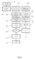
- FIG. 7 shows a flow chart for the high level software method embodied by the present novel system.
- FIG. 8 shows a flow chart for creating BGRs through virtual tessellation in the resident server.
- FIG. 9 shows an alternative method for creating BGRs in the resident server.
- FIG. 10 shows a flow chart for fleet customer set-up on the resident server.
- FIG. 11 shows is a flow chart of a server based navigation method using BGRs and Node Pairs.
- FIG. 12 shows a flow chart for the hand-held or remote electronic device software process.
- FIG. 13 shows the Earth inscribed in a tessellated cube.
- FIG. 7 shows a high level flow chart for the software method associated with the system. Some operations are only performed on set-up of operation: 99 initial START, 26 loading map database; 62 create BGRs through sub-routine, and 56 system initialization.
- the map database 26 can be purchased from any map database vendor, or a crowd-sourced map database can be used.
- the system initialization includes such administrative routines as forming the NPLUT, populating the NPLUT with any available data, creating a user database, populating the user database with any available data, and similar tasks.
- FIG. 13 shows the Earth 301 inscribed in a tessellated cube 302 .
- the virtual Earth 301 can be rotated or tilted until a geographic land mass of interest is centered.
- the geographic region of interest can be made to be almost parallel with a face of the inscribing cube 302 .
- This method is called Virtual Tessellation, because the pattern on the Earth 301 is not technically a tessellation, because all of the BGRs will not be the same shape and size.
- FIG. 8 shows a method of generating BGRs using Virtual Tessellation.
- the system inscribes the Earth in a cube 44 .
- the center of the cube face 45 is centered over the geographic region of interest.
- a starting tessellation size 46 for the face of the cube is selected.
- the Standard Surface Area (“SSA”) is the target surface area for the BGRs.
- a BGR SSA of approximately 1 sq. km seems ideal.
- the variation limit for the SSA 64 is set. This number should be small (less than 10%). All BGRs should have a surface area very close to the SSA in order to minimize the potential for confounded data (non-orthogonal independent variables during an analysis of variance).
- the size of the tessellation squares 47 on the inscribing cube can be varied. Although this is computationally more difficult, it will minimize SSA variation (only the inner most piece is a square, with each proceeding layer being rectangles with higher and higher aspect ratios.
- the cube tessellation is projected onto the Earth 48 to create initial BGRs.
- the SSA of all BGRs is assessed 49 . If the SSA analysis is okay 50 , the BGRs are stored 53 , and the BGR generation process ends 59 . If the SSA analysis is not okay 50 , all the BGRs are erased 51 .
- the system adjusts the starting tessellation size 52 , the outer layer tessellation ratio (how quickly the outer layers of the tessellated cube face become rectangles of higher and higher aspect ratio) is adjusted 63 , and adjust the SSA variation limit 64 . The whole process is then started again 47 .
- FIG. 9 shows the flow chart for an alternative embodiment for generating BGRs.
- the process is started 58 by finding the centroid of the geographic region of interest 65 .
- a single BGR is created 66 with a surface area equal to the SSA and at least four sides.
- the SSA variation limit is set 64 .
- a layer of BGRs is created around the existing BGR(s), in which the new layer of BGRs has its perimeter minimized 67 .
- the SSA for the layer is analyzed 49 . As long as the SSA analysis is okay, additional layers of BGRs are added. If the SSA is not okay 50 , the SSA for just the last layer is analyzed 69 .
- the BGRs are stored 71 . If it is not edge geography 70 , the last layer of BGRs is erased 51 . The allowable maximum perimeter will be increased by 10% from the previous iteration 68 , and a new layer of BGRs will be created 67 . The process continues until the entire geographic region of interest is covered with BGRs 72 .
- Fleet Set-up 61 ( FIG. 10 ) can occur.
- each customer or fleet is enrolled with a Fleet Set Up 80 .
- Data collected about Fleet Vehicles 81 includes number of vehicles 82 , types of vehicles (including fuel type) 83 , mileage of vehicles 84 , and other user defined vehicle data (independent variable or attribute data) 85 .
- Data collected about drivers includes name 87 , driver number or identifier 88 , employment type (employee, independent contractor, owner/operator, etc.) 89 , and other user defined driver data (independent variable or attribute data) 90 .
- Data collected about fleet services includes customer type 92 , service standards 93 , service area 94 , and other user defined service data (independent variable and attribute data) 95 .
- the database also allows user defined fueling stations 96 . Once all of the data has been defined, it is loaded into a database 97 , and the routine ends 98 .
- FIG. 1 shows an embodiment of wireless communication and geo-location, which is necessary for navigation.
- the end user is in a vehicle 201 , which has a remote electronic device (“RED”), either built-in or mounted.
- the vehicle 201 geo-locates via a GPS chip-set, a gyro, and/or a satellite transceiver.
- a plurality of satellites 200 provides GPS signals to the vehicle's 201 GPS transceiver.
- the vehicle 201 is then able to communicate its location to a central server 203 , using a wireless network 202 .
- the wireless network 202 can be a cellular or mobile phone network, a radio-frequency network, or other wireless means.
- the transmission could also be made over a mixed means network, such as a wi-fi network that downloads and uploads requests to the server via a wired internet connection (not shown).
- FIG. 2 shows an alternative embodiment for the communication and geo-location system.
- the vehicle 201 has been replaced with a cellphone, MDT, or RED 204 .
- the cellphone, MDT, or RED 204 geo-locates via the satellite network 200 .
- the cellphone, MDT, or RED 204 communicates with the server 203 , via a wireless network 202 .
- FIG. 3 shows an alternative embodiment for the communication and geo-location system in FIG. 2 .
- the wireless network 202 is used for both geo-location and communication with the server.
- the cellphone, MDT or RED 204 can use multiple cellphone towers or antennae to identify its current location. This data can be transmitted, along with a navigation request, to the remote server 203 .
- FIG. 4 shows an alternative embodiment for the communication and geo-location system in FIG. 2 .
- satellites 200 are used for both geo-location and communication.
- GPS satellites are not currently multi-tasked for communication, it is conceivable, in the future, that both geo-location information and communication would happen with the same satellite 200 .
- this system is architected according to current satellite trends: one set of satellites 200 provides geo-location information, and another satellite 200 is used for communication to the remote server 203 .
- FIG. 5 shows an alternative embodiment for the communication and geo-location system in FIG. 1 .
- the wireless network 202 is used for both geo-location and communication with the server.
- the vehicle 201 can use multiple cellphone towers or antennae to identify its current location. This data can be transmitted, along with a navigation request, to the remote server 203 .
- FIG. 6 shows an alternative embodiment for the communication and geo-location system in FIG. 1 .
- satellites 200 are used for both geo-location and communication.
- One set of satellites 200 provides geo-location information, and another satellite 200 is used for communication to the remote server 203 .
- an end-user nav request 32 is communicated through one of the communication and geo-location systems in FIG. 1 through FIG. 6 .
- the user interacts with the system through a user software method, generally referred to as a user application.
- the User Application starts 101 by insuring that the user is registered 102 . If the user is registered 102 , destination input 128 occurs. The user can add multiple destinations 127 , 128 , either specifying the order or allowing the system to order the trip. Once input is complete 127 , the data is transmitted 129 to the remote server via the means shown in FIGS. 1-6 .
- the remote server 203 transmits the route, where it is received 129 by the end user.
- the end user's application 101 will ping 130 the remote server 203 , by transmitting 126 its location.
- the remote server 203 will compare the user's progress versus what the remote server predicts the user's progress ought to be—If the progress towards the destination lies outside the acceptance criteria, the remote server 203 will transmit a re-route signal 125 to the user's application 101 .
- the end user's unit will notify the end user of the re-route, while the remote server 203 provides an alternative route.
- the new route will be received 126 by the end user's application 101 .
- the end user will arrive at the destination 124 .
- the end user's application 101 will transmit a final ping 123 to the remote server 203 , so that the remote server has a complete history of the trip.
- the unit can allow registration by opening an account 103 .
- the user selects ping frequency 104 , navigation preferences 106 , and navigation exclusions 105 .
- the user then has to complete independent variables concerning him- or herself, and his or her vehicle.
- Driver information 107 includes years driving 108 , driving record 109 , miles driven per year 110 , age 111 , marital status 112 , home address 113 , where the user learned to drive 114 , the user's profession 115 , the user's gender 116 , and other company- or group-defined data 117 .
- the vehicle information 118 includes vehicle owner 119 , make and model 120 , model year 121 and miles on the vehicle 122 .
- the independent variable data should be of very high quality, because the user will be aware that their accuracy in answering the questions may directly relate to how well the system can navigate for them.
- FIG. 7 shows that Guidance 60 occurs after End User Input 32 .
- Guidance 60 begins by selecting nav optimizing factors 1 . Once the BGRs have been created, it is possible for the invention to create navigation solutions.
- FIG. 11 shows a single vehicle navigation solution. The user starts by selecting an optimizing factor 1 , or dependent variable: time, distance, fuel, cost, or an user defined dependent variable. Next, the user, if desired, excludes certain solutions from consideration 2 , such as interstates, tollways, bridges, or other potential routes. The user enters one or more destinations 3 using the input device. If inputting more than one destination, the user can select 6 an automatic 10 or manual 5 ordering of the destinations.
- the automatic destination ordering module 10 When selecting a manual 5 ordering, the automatic destination ordering module 10 will defer to the manual entry. Once ordered, the origin and the next or only destination is identified 9 . If there is only a single destination input at the beginning 7 , the navigation core moves directly to identifying origin and destination 9 .
- the invention will identify the BGRs that lie, linearly, between the origin and destination 8 , and designates them as Active. These BGRs are termed Gen 1. In the BGR containing the origin, the origin is designated the sole entry node 12 . In the BGR containing the current destination 9 , the current destination is designated as the sole exit node 13 . In all other BGRs, Node Pairs are created by selecting only those nodes which have a BGR on both sides 11 . The navigation core than creates a Node Pairs list for all Active BGRs 16 .
- the navigation core will simultaneously create a temporary BGR array for all Node Pairs under consideration 20 , and survey the NPLUT 14 to see if solutions exist for any Node Pairs under consideration 17 . If the Node Pairs solution exists in the NPLUT, it is placed in the temporary BGR array 20 . If not, using weighting functions for each street classification, the invention makes dependent variable calculations for each Node Pair of each BGR 19 , capturing route information for each potential solution. The invention will delete any exclusions from the potential solution set 21 . Since only a limited set of BGRs are used for the initial calculation, not all nodes of each BGR is a potential entry and/or exit.
- the data generated from the nodes of interest can be stored in an array, in a temporary database format, or in any other data-handling format that allows quick access 20 .
- This temporary data can be stored in cache storage, on the hard-drive, or in any other type of suitable memory element. In a multi-core processor environment, such calculations are speedy, because each BGRs can be independently calculated.
- the invention then creates an initial trial route by finding the initial minimum solution from the origin to the destination, travelling only through BGRs that lie, linearly, between the origin and destination 22 .
- the exit node of one BGR is the entry node of the adjoining BGR.
- Gen 1 BGRs now use all nodes in the calculation.
- Gen 2 BGRs use a reduced set of nodes, because not all nodes have an adjoining BGR associated with them.
- the potential solutions calculated in the Gen 1 calculation are excluded, because they are found in the temporary array 20 .
- the invention again, applies the boundary condition that the exit node of one BGR is the entry node of the adjoining BGR.
- the invention yields an explicit solution, the Gen 2 trial route 22 .
- Gen 3 The process is repeated for Gen 3, in much the same way as for Gen 2 23 , 18 . All BGRs adjoining Gen 2 BGRs are added to the calculation. All previously considered trial solutions are excluded from the potential solution set. An explicit solution for the Gen 3 trial route is calculated.
- Gen A the optimum solution.
- C the total number of generations
- A the optimum generation
- B the number of desired divergent solutions calculated after the optimum solution.
- B is related to the distance between the origin and destination 23 . Additionally, selection of B can be optimized through a simple error feedback function, where the error is related to the distance.
- the upper limit of B is set by the maximum speed limit. In other words, the process ends when the vehicle would have to exceed the maximum allowable speed limit around the periphery in order to offer a more preferable solution to the dependent variable than the currently available solution.
- Initial destinations are determined by minimizing the number of BGRs traversed in order for all vehicles to get to a preliminary destination.
- the above algorithm creates a Route. At the first destination each vehicle is again assigned a destination, with the system attempting to minimize the number of BGRs traversed in order to get all vehicles to their next destination. In this way, it is possible to handle multiple vehicle multiple destination problems, with or without Constraints.
Landscapes
- Engineering & Computer Science (AREA)
- Radar, Positioning & Navigation (AREA)
- Remote Sensing (AREA)
- Physics & Mathematics (AREA)
- General Physics & Mathematics (AREA)
- Business, Economics & Management (AREA)
- Human Resources & Organizations (AREA)
- Automation & Control Theory (AREA)
- Strategic Management (AREA)
- Economics (AREA)
- Theoretical Computer Science (AREA)
- Signal Processing (AREA)
- Computer Networks & Wireless Communication (AREA)
- Marketing (AREA)
- Quality & Reliability (AREA)
- General Business, Economics & Management (AREA)
- Development Economics (AREA)
- Tourism & Hospitality (AREA)
- Game Theory and Decision Science (AREA)
- Operations Research (AREA)
- Entrepreneurship & Innovation (AREA)
- Data Mining & Analysis (AREA)
- Databases & Information Systems (AREA)
- General Engineering & Computer Science (AREA)
- Mathematical Physics (AREA)
- Software Systems (AREA)
- Traffic Control Systems (AREA)
- Navigation (AREA)
- Instructional Devices (AREA)
Priority Applications (7)
| Application Number | Priority Date | Filing Date | Title |
|---|---|---|---|
| US13/660,977 US8775059B2 (en) | 2011-10-26 | 2012-10-25 | Method and system for fleet navigation, dispatching and multi-vehicle, multi-destination routing |
| EP12842889.3A EP2771807B1 (de) | 2011-10-26 | 2012-10-26 | Verfahren und system für flottennavigation, aussendung und leitweglenkung mehrerer fahrzeuge und destinationen |
| CN201280064665.8A CN104025075A (zh) | 2011-10-26 | 2012-10-26 | 用于车队导航、调度以及多个车辆、多个目的地指定路线的方法及系统 |
| PCT/US2012/062238 WO2013063480A1 (en) | 2011-10-26 | 2012-10-26 | Method and system for fleet navigation, dispatching and multi-vehicle, multi-destination routing |
| RU2014119436A RU2629438C2 (ru) | 2011-10-26 | 2012-10-26 | Способ и система для навигации транспортного парка, диспетчеризация и прокладка маршрута для множества транспортных средств и множества мест назначения |
| JP2014539076A JP2015500981A (ja) | 2011-10-26 | 2012-10-26 | フリートナビゲーション、ディスパッチ及び複数の自動車で、複数の目的地を探索するための方法及びシステム |
| US15/206,097 USRE47985E1 (en) | 2011-10-26 | 2016-07-08 | Method and system for fleet navigation, dispatching and multi-vehicle, multi-destination routing |
Applications Claiming Priority (2)
| Application Number | Priority Date | Filing Date | Title |
|---|---|---|---|
| US201161628147P | 2011-10-26 | 2011-10-26 | |
| US13/660,977 US8775059B2 (en) | 2011-10-26 | 2012-10-25 | Method and system for fleet navigation, dispatching and multi-vehicle, multi-destination routing |
Related Child Applications (1)
| Application Number | Title | Priority Date | Filing Date |
|---|---|---|---|
| US15/206,097 Reissue USRE47985E1 (en) | 2011-10-26 | 2016-07-08 | Method and system for fleet navigation, dispatching and multi-vehicle, multi-destination routing |
Publications (2)
| Publication Number | Publication Date |
|---|---|
| US20130110385A1 US20130110385A1 (en) | 2013-05-02 |
| US8775059B2 true US8775059B2 (en) | 2014-07-08 |
Family
ID=48168594
Family Applications (2)
| Application Number | Title | Priority Date | Filing Date |
|---|---|---|---|
| US13/660,977 Ceased US8775059B2 (en) | 2011-10-26 | 2012-10-25 | Method and system for fleet navigation, dispatching and multi-vehicle, multi-destination routing |
| US15/206,097 Expired - Fee Related USRE47985E1 (en) | 2011-10-26 | 2016-07-08 | Method and system for fleet navigation, dispatching and multi-vehicle, multi-destination routing |
Family Applications After (1)
| Application Number | Title | Priority Date | Filing Date |
|---|---|---|---|
| US15/206,097 Expired - Fee Related USRE47985E1 (en) | 2011-10-26 | 2016-07-08 | Method and system for fleet navigation, dispatching and multi-vehicle, multi-destination routing |
Country Status (6)
| Country | Link |
|---|---|
| US (2) | US8775059B2 (de) |
| EP (1) | EP2771807B1 (de) |
| JP (1) | JP2015500981A (de) |
| CN (1) | CN104025075A (de) |
| RU (1) | RU2629438C2 (de) |
| WO (1) | WO2013063480A1 (de) |
Cited By (6)
| Publication number | Priority date | Publication date | Assignee | Title |
|---|---|---|---|---|
| US20130218469A1 (en) * | 2010-09-28 | 2013-08-22 | Brian Charles Hargrave Turton | Telecommunications network routing |
| US10928215B2 (en) | 2018-08-21 | 2021-02-23 | Honda Motor Co., Ltd. | Methods and systems for last mile navigation cache point of interest |
| US10977585B2 (en) | 2015-01-29 | 2021-04-13 | Beijing Didi Infinity Technology And Development Co., Ltd. | Order allocation system and method |
| US11168998B2 (en) | 2018-08-21 | 2021-11-09 | Honda Motor Co., Ltd. | Methods and systems for last mile navigation cache point of interest |
| US12018949B2 (en) | 2018-11-07 | 2024-06-25 | Google Llc | Providing navigation instructions to one device in view of another device |
| US12041041B2 (en) * | 2019-08-21 | 2024-07-16 | Truist Bank | Location-based mobile device authentication |
Families Citing this family (38)
| Publication number | Priority date | Publication date | Assignee | Title |
|---|---|---|---|---|
| US10109026B2 (en) | 2010-10-06 | 2018-10-23 | Tillster, Inc. | Mobile restaurant ordering system |
| US10102596B2 (en) * | 2010-10-06 | 2018-10-16 | Tillster, Inc. | Customer interface restaurant system |
| US8868332B2 (en) * | 2011-10-26 | 2014-10-21 | Right There Ware LLC | Method and system for navigation using bounded geograhic regions |
| US11574263B2 (en) | 2013-03-15 | 2023-02-07 | Via Transportation, Inc. | System and method for providing multiple transportation proposals to a user |
| RU2682313C2 (ru) | 2014-04-24 | 2019-03-18 | Бэйцзинь Диди Инфинити Текнолоджи Энд Дивелопмент Ко., Лтд. | Система (варианты) и способ (варианты) управления предоставлением услуги |
| US20170167882A1 (en) * | 2014-08-04 | 2017-06-15 | Xerox Corporation | System and method for generating available ride-share paths in a transportation network |
| US10593005B2 (en) * | 2014-09-03 | 2020-03-17 | Meru Cab Company Private Limited | Dynamic forecasting for forward reservation of cab |
| CN104197949A (zh) * | 2014-09-15 | 2014-12-10 | 江苏南亿迪纳数字科技发展有限公司 | 一种远程互助式车联网应用系统的实现方法 |
| US20160148136A1 (en) * | 2014-11-24 | 2016-05-26 | Boyi Ni | Multiple sequential planning and allocation of time-divisible resources |
| CN107209019B (zh) * | 2015-01-30 | 2021-01-15 | 索尼公司 | 信息处理系统和控制方法 |
| CN104697516B (zh) * | 2015-03-17 | 2018-03-23 | 徐军 | 移动终端以及行程引导方法 |
| US9562785B1 (en) * | 2015-07-20 | 2017-02-07 | Via Transportation, Inc. | Continuously updatable computer-generated routes with continuously configurable virtual bus stops for passenger ride-sharing of a fleet of ride-sharing vehicles and computer transportation systems and computer-implemented methods for use thereof |
| JP2018531474A (ja) * | 2015-08-26 | 2018-10-25 | ぺロトン テクノロジー インコーポレイテッド | 車両監視及び隊列走行装置、システム、並びに方法 |
| CN105261230A (zh) * | 2015-11-19 | 2016-01-20 | 北京九五智驾信息技术股份有限公司 | 车队管理方法及装置 |
| US10546254B2 (en) * | 2016-01-26 | 2020-01-28 | Oracle International Corporation | System and method for efficient storage of point-to-point traffic patterns |
| RU2674129C2 (ru) * | 2016-05-12 | 2018-12-04 | Общество с ограниченной ответственностью "Ситиликс" | Способ и система для определения, визуализации и прогнозирования транспортной доступности районов населённого пункта |
| US9857188B1 (en) * | 2016-06-29 | 2018-01-02 | Uber Technologies, Inc. | Providing alternative routing options to a rider of a transportation management system |
| CN106126723A (zh) * | 2016-06-30 | 2016-11-16 | 乐视控股(北京)有限公司 | 一种移动目标对象的方法及装置 |
| CN106248092A (zh) * | 2016-07-31 | 2016-12-21 | 北京九五智驾信息技术股份有限公司 | 导航方法 |
| CN106709591A (zh) * | 2016-08-11 | 2017-05-24 | 淮阴工学院 | 一种车联网环境下不确定需求的协同拼车路线选择方法 |
| SG10201609375XA (en) * | 2016-11-09 | 2018-06-28 | Cyclect Electrical Eng Pte Ltd | Vehicle, system and method for remote convoying |
| GB201711408D0 (en) * | 2016-12-30 | 2017-08-30 | Maxu Tech Inc | Early entry |
| US10677602B2 (en) | 2017-01-25 | 2020-06-09 | Via Transportation, Inc. | Detecting the number of vehicle passengers |
| WO2019023324A1 (en) | 2017-07-26 | 2019-01-31 | Via Transportation, Inc. | SYSTEMS AND METHODS FOR MANAGING AND ROUTING COOPERATING VEHICLES |
| JP6274545B1 (ja) * | 2017-08-10 | 2018-02-07 | フューネラル サービス ワーカーズ アカデミー,インク.Funeral service workers academy,Inc. | 霊柩寝台車配車サーバ |
| US20190120640A1 (en) * | 2017-10-19 | 2019-04-25 | rideOS | Autonomous vehicle routing |
| MX2020004484A (es) * | 2017-11-17 | 2020-08-03 | Nissan Motor | Dispositivo de asistencia a la operacion para vehiculos. |
| CN111670467A (zh) * | 2017-11-30 | 2020-09-15 | 罗伯特·博世有限公司 | 具有优先级因素层级的车辆车队管理 |
| WO2019136341A1 (en) | 2018-01-08 | 2019-07-11 | Via Transportation, Inc. | Systems and methods for managing and scheduling ridesharing vehicles |
| US11620592B2 (en) | 2018-04-09 | 2023-04-04 | Via Transportation, Inc. | Systems and methods for planning transportation routes |
| US11293770B2 (en) * | 2018-08-02 | 2022-04-05 | salesforces.com, Inc. | Geographic routing engine |
| US10274326B1 (en) * | 2018-08-02 | 2019-04-30 | Mapanything, Inc. | Utilizing a geo-locator service and zone servers to reduce computer resource requirements for determining high quality solutions to routing problems |
| CN109903137A (zh) * | 2019-02-27 | 2019-06-18 | 杭州优行科技有限公司 | 派单区域确定方法、装置、服务器及计算机可读存储介质 |
| US11493353B1 (en) | 2019-03-31 | 2022-11-08 | Gm Cruise Holdings Llc | Autonomous vehicle consumption of real-time public transportation data to guide curb access and usage |
| CN110991651B (zh) * | 2019-11-30 | 2023-04-28 | 航天科技控股集团股份有限公司 | 一种基于tbox的用户驾驶习惯的能耗预测分析系统及方法 |
| CN111696340A (zh) * | 2020-05-15 | 2020-09-22 | 深圳市元征科技股份有限公司 | 一种车辆控制的方法、装置及设备 |
| RU2770938C1 (ru) * | 2021-04-25 | 2022-04-25 | Николай Анатольевич Грязнов | Коммуникационно-навигационная система для управления транспортными потоками |
| CN117711610B (zh) * | 2024-02-05 | 2024-04-26 | 四川省医学科学院·四川省人民医院 | 一种网络化mdt多学科的远程会诊车系统 |
Citations (5)
| Publication number | Priority date | Publication date | Assignee | Title |
|---|---|---|---|---|
| US20030191578A1 (en) * | 2000-03-14 | 2003-10-09 | Cynthia Paulauskas | Method and system for providing reminders about points of interests while traveling |
| US20060058941A1 (en) * | 1999-04-19 | 2006-03-16 | Dekock Bruce W | System for providing traffic information |
| US20080051995A1 (en) * | 2006-08-25 | 2008-02-28 | Magellan Navigation, Inc. | Rerouting in Vehicle Navigation Systems |
| US20080195428A1 (en) * | 2007-02-12 | 2008-08-14 | O'sullivan Sean | Shared transport system and service network |
| US20100332113A1 (en) * | 2009-06-24 | 2010-12-30 | General Motors Corporation | System and method for providing route guidance to a requesting vehicle |
Family Cites Families (24)
| Publication number | Priority date | Publication date | Assignee | Title |
|---|---|---|---|---|
| EP1134674A4 (de) * | 1998-11-24 | 2010-06-09 | Panasonic Corp | Datenstruktur fpür dugutale karte |
| JP2002183892A (ja) * | 2000-12-12 | 2002-06-28 | Sharp Corp | 車両の運行経路選出方法およびそれを用いた配車管理方法、配車管理システム |
| JP4108291B2 (ja) * | 2001-04-16 | 2008-06-25 | 三菱電機株式会社 | 移動体ナビゲーション装置及び移動体ナビゲーション方法 |
| FR2831870B1 (fr) * | 2001-11-08 | 2004-08-13 | Airbus France | Procede et dispositif pour afficher un vecteur vitesse d'un aeronef |
| JP2003168195A (ja) * | 2001-12-03 | 2003-06-13 | Denso Corp | 配車サービス方法、配車サービスシステム、配車サービス装置、利用者用端末装置、事業者用端末装置、事業者用車載機 |
| JPWO2004057273A1 (ja) * | 2002-12-20 | 2006-04-20 | ジクー・データシステムズ株式会社 | 経路探索装置、経路探索システム、プログラム、及び経路探索方法 |
| US7493309B2 (en) * | 2003-01-16 | 2009-02-17 | International Business Machines Corporation | Framework for dynamic analysis of varying structured data using multiple analysis techniques |
| JP2004301667A (ja) * | 2003-03-31 | 2004-10-28 | Clarion Co Ltd | 経路配信サーバ、経路配信方法および経路配信プログラム並びに経路配信システム |
| US7627422B2 (en) * | 2003-06-24 | 2009-12-01 | At&T Intellectual Property I, Lp | Methods, systems and computer program products for ride matching based on selection criteria and drive characteristic information |
| JP2005164410A (ja) * | 2003-12-03 | 2005-06-23 | Nissan Motor Co Ltd | ナビゲーション装置およびナビゲーション方法 |
| US7539666B2 (en) * | 2004-04-06 | 2009-05-26 | International Business Machines Corporation | Method, system and program for managing geographic data stored in a database |
| US7425952B2 (en) * | 2004-11-23 | 2008-09-16 | Metavr, Inc. | Three-dimensional visualization architecture |
| US7698061B2 (en) * | 2005-09-23 | 2010-04-13 | Scenera Technologies, Llc | System and method for selecting and presenting a route to a user |
| JP4554653B2 (ja) * | 2007-08-08 | 2010-09-29 | クラリオン株式会社 | 経路探索方法、経路探索システムおよびナビゲーション装置 |
| CN101149268A (zh) * | 2007-10-30 | 2008-03-26 | 上海上大鼎正软件有限公司 | 一种导航用道路拓扑数据模型和计算方法 |
| DE102007057715A1 (de) * | 2007-11-30 | 2009-06-04 | Robert Bosch Gmbh | Verfahren zur Routenbestimmung und Anordnung dazu |
| JP5234339B2 (ja) * | 2008-08-13 | 2013-07-10 | クラリオン株式会社 | 計算機システム及び経路案内方法 |
| JP5551896B2 (ja) | 2009-06-29 | 2014-07-16 | 株式会社日立製作所 | ナビゲーション装置、経路探索サーバ、および経路探索システム |
| US9219500B2 (en) * | 2009-07-09 | 2015-12-22 | Tomtom International B.V. | Navigation devices and methods carried out thereon |
| WO2011004926A1 (ko) * | 2009-07-10 | 2011-01-13 | Kim Soon Yeong | 가금류 사육장 |
| JP2011033447A (ja) * | 2009-07-31 | 2011-02-17 | Clarion Co Ltd | ナビゲーション装置及びその表示方法 |
| RU2417424C1 (ru) * | 2009-12-30 | 2011-04-27 | Закрытое акционерное общество Научно-производственное предприятие "Реляционные экспертные системы" | Способ компрессии многомерных данных для хранения и поиска информации в системе управления базами данных и устройство для его осуществления |
| US8498953B2 (en) * | 2010-03-30 | 2013-07-30 | Sap Ag | Method for allocating trip sharing |
| JP5547106B2 (ja) * | 2011-02-01 | 2014-07-09 | クラリオン株式会社 | 経路演算装置 |
-
2012
- 2012-10-25 US US13/660,977 patent/US8775059B2/en not_active Ceased
- 2012-10-26 JP JP2014539076A patent/JP2015500981A/ja active Pending
- 2012-10-26 EP EP12842889.3A patent/EP2771807B1/de not_active Not-in-force
- 2012-10-26 CN CN201280064665.8A patent/CN104025075A/zh active Pending
- 2012-10-26 RU RU2014119436A patent/RU2629438C2/ru not_active IP Right Cessation
- 2012-10-26 WO PCT/US2012/062238 patent/WO2013063480A1/en active Application Filing
-
2016
- 2016-07-08 US US15/206,097 patent/USRE47985E1/en not_active Expired - Fee Related
Patent Citations (5)
| Publication number | Priority date | Publication date | Assignee | Title |
|---|---|---|---|---|
| US20060058941A1 (en) * | 1999-04-19 | 2006-03-16 | Dekock Bruce W | System for providing traffic information |
| US20030191578A1 (en) * | 2000-03-14 | 2003-10-09 | Cynthia Paulauskas | Method and system for providing reminders about points of interests while traveling |
| US20080051995A1 (en) * | 2006-08-25 | 2008-02-28 | Magellan Navigation, Inc. | Rerouting in Vehicle Navigation Systems |
| US20080195428A1 (en) * | 2007-02-12 | 2008-08-14 | O'sullivan Sean | Shared transport system and service network |
| US20100332113A1 (en) * | 2009-06-24 | 2010-12-30 | General Motors Corporation | System and method for providing route guidance to a requesting vehicle |
Cited By (7)
| Publication number | Priority date | Publication date | Assignee | Title |
|---|---|---|---|---|
| US20130218469A1 (en) * | 2010-09-28 | 2013-08-22 | Brian Charles Hargrave Turton | Telecommunications network routing |
| US9671229B2 (en) * | 2010-09-28 | 2017-06-06 | Airbus Defence And Space Limited | Telecommunications network routing |
| US10977585B2 (en) | 2015-01-29 | 2021-04-13 | Beijing Didi Infinity Technology And Development Co., Ltd. | Order allocation system and method |
| US10928215B2 (en) | 2018-08-21 | 2021-02-23 | Honda Motor Co., Ltd. | Methods and systems for last mile navigation cache point of interest |
| US11168998B2 (en) | 2018-08-21 | 2021-11-09 | Honda Motor Co., Ltd. | Methods and systems for last mile navigation cache point of interest |
| US12018949B2 (en) | 2018-11-07 | 2024-06-25 | Google Llc | Providing navigation instructions to one device in view of another device |
| US12041041B2 (en) * | 2019-08-21 | 2024-07-16 | Truist Bank | Location-based mobile device authentication |
Also Published As
| Publication number | Publication date |
|---|---|
| JP2015500981A (ja) | 2015-01-08 |
| EP2771807A1 (de) | 2014-09-03 |
| WO2013063480A4 (en) | 2013-08-08 |
| EP2771807B1 (de) | 2017-12-06 |
| RU2014119436A (ru) | 2015-12-10 |
| RU2629438C2 (ru) | 2017-08-29 |
| USRE47985E1 (en) | 2020-05-12 |
| WO2013063480A1 (en) | 2013-05-02 |
| EP2771807A4 (de) | 2015-07-22 |
| US20130110385A1 (en) | 2013-05-02 |
| CN104025075A (zh) | 2014-09-03 |
Similar Documents
| Publication | Publication Date | Title |
|---|---|---|
| USRE47985E1 (en) | Method and system for fleet navigation, dispatching and multi-vehicle, multi-destination routing | |
| USRE47107E1 (en) | Method and system for navigation using bounded geographic regions | |
| US20090063045A1 (en) | Gps based fuel efficiency optimizer | |
| US11692837B2 (en) | Automatic discovery of optimal routes for flying cars and drones | |
| US8738289B2 (en) | Advanced routing of vehicle fleets | |
| RU2407060C2 (ru) | Навигационное устройство для планирования зависящего от времени маршрута | |
| US20140222950A1 (en) | Predictive Mobile Map Download | |
| US20150292894A1 (en) | Travel route | |
| US9301099B2 (en) | Method of analyzing points of interest with probe data | |
| US20080172172A1 (en) | Route planning process | |
| US20180364061A1 (en) | Methods and systems for efficient and timely transportation of heavy-duty trucks | |
| US20180314998A1 (en) | Resource Allocation in a Network System | |
| US10274329B2 (en) | Method and apparatus for providing a minimum overlapping alternative path | |
| US9754226B2 (en) | Urban computing of route-oriented vehicles | |
| US20200011690A1 (en) | Method, apparatus, and computer program product for generation of a route including multiple waypoints | |
| US10972900B2 (en) | Method and apparatus for providing selected access to user mobility data based on a quality of service | |
| US12123726B2 (en) | Method and apparatus for ridesharing pickup wait time prediction | |
| Gkiotsalitis et al. | A mobile application for real-time multimodal routing under a set of users’ preferences | |
| TWI635447B (zh) | 乘車需求量預測方法及系統 | |
| CN113112850A (zh) | 众包导航系统和方法 | |
| US20240183671A1 (en) | Providing Navigational Instructions Based On Contextual Data | |
| US20230177444A1 (en) | Territory set determination based on historical service event data | |
| US20240320582A1 (en) | Systems and methods for planning transit systems containing fixed route and on-demand services | |
| US20240104491A1 (en) | Auto-Constraint Generation for the Optimization of Planned Pickups and Deliveries | |
| US20230053647A1 (en) | Systems and methods for reachability of different destinations |
Legal Events
| Date | Code | Title | Description |
|---|---|---|---|
| AS | Assignment |
Owner name: RIGHTTHEREWARE LLC, MICHIGAN Free format text: ASSIGNMENT OF ASSIGNORS INTEREST;ASSIGNORS:HEED, THOMAS P, MR.;HEED, JOHN C, MR.;REEL/FRAME:032752/0951 Effective date: 20140424 |
|
| STCF | Information on status: patent grant |
Free format text: PATENTED CASE |
|
| RF | Reissue application filed |
Effective date: 20160708 |
|
| FEPP | Fee payment procedure |
Free format text: MAINTENANCE FEE REMINDER MAILED (ORIGINAL EVENT CODE: REM.) |
|
| FEPP | Fee payment procedure |
Free format text: SURCHARGE FOR LATE PAYMENT, MICRO ENTITY (ORIGINAL EVENT CODE: M3554) |
|
| MAFP | Maintenance fee payment |
Free format text: PAYMENT OF MAINTENANCE FEE, 4TH YEAR, MICRO ENTITY (ORIGINAL EVENT CODE: M3551) Year of fee payment: 4 |