US8711397B2 - Printing system, information processing apparatus, print job processing method, information processing method, program, and storage medium - Google Patents
Printing system, information processing apparatus, print job processing method, information processing method, program, and storage medium Download PDFInfo
- Publication number
- US8711397B2 US8711397B2 US12/610,250 US61025009A US8711397B2 US 8711397 B2 US8711397 B2 US 8711397B2 US 61025009 A US61025009 A US 61025009A US 8711397 B2 US8711397 B2 US 8711397B2
- Authority
- US
- United States
- Prior art keywords
- capability information
- device capability
- print job
- printing system
- identification information
- Prior art date
- Legal status (The legal status is an assumption and is not a legal conclusion. Google has not performed a legal analysis and makes no representation as to the accuracy of the status listed.)
- Active, expires
Links
Images


Classifications
-
- H—ELECTRICITY
- H04—ELECTRIC COMMUNICATION TECHNIQUE
- H04N—PICTORIAL COMMUNICATION, e.g. TELEVISION
- H04N1/00—Scanning, transmission or reproduction of documents or the like, e.g. facsimile transmission; Details thereof
- H04N1/00127—Connection or combination of a still picture apparatus with another apparatus, e.g. for storage, processing or transmission of still picture signals or of information associated with a still picture
- H04N1/00204—Connection or combination of a still picture apparatus with another apparatus, e.g. for storage, processing or transmission of still picture signals or of information associated with a still picture with a digital computer or a digital computer system, e.g. an internet server
- H04N1/00209—Transmitting or receiving image data, e.g. facsimile data, via a computer, e.g. using e-mail, a computer network, the internet, I-fax
- H04N1/00222—Transmitting or receiving image data, e.g. facsimile data, via a computer, e.g. using e-mail, a computer network, the internet, I-fax details of image data generation or reproduction, e.g. scan-to-email or network printing
- H04N1/00233—Transmitting or receiving image data, e.g. facsimile data, via a computer, e.g. using e-mail, a computer network, the internet, I-fax details of image data generation or reproduction, e.g. scan-to-email or network printing details of image data reproduction, e.g. network printing or remote image display
-
- G—PHYSICS
- G06—COMPUTING; CALCULATING OR COUNTING
- G06F—ELECTRIC DIGITAL DATA PROCESSING
- G06F3/00—Input arrangements for transferring data to be processed into a form capable of being handled by the computer; Output arrangements for transferring data from processing unit to output unit, e.g. interface arrangements
- G06F3/12—Digital output to print unit, e.g. line printer, chain printer
- G06F3/1201—Dedicated interfaces to print systems
- G06F3/1202—Dedicated interfaces to print systems specifically adapted to achieve a particular effect
- G06F3/1203—Improving or facilitating administration, e.g. print management
- G06F3/1204—Improving or facilitating administration, e.g. print management resulting in reduced user or operator actions, e.g. presetting, automatic actions, using hardware token storing data
-
- G—PHYSICS
- G06—COMPUTING; CALCULATING OR COUNTING
- G06F—ELECTRIC DIGITAL DATA PROCESSING
- G06F3/00—Input arrangements for transferring data to be processed into a form capable of being handled by the computer; Output arrangements for transferring data from processing unit to output unit, e.g. interface arrangements
- G06F3/12—Digital output to print unit, e.g. line printer, chain printer
- G06F3/1201—Dedicated interfaces to print systems
- G06F3/1202—Dedicated interfaces to print systems specifically adapted to achieve a particular effect
- G06F3/1203—Improving or facilitating administration, e.g. print management
- G06F3/1205—Improving or facilitating administration, e.g. print management resulting in increased flexibility in print job configuration, e.g. job settings, print requirements, job tickets
-
- G—PHYSICS
- G06—COMPUTING; CALCULATING OR COUNTING
- G06F—ELECTRIC DIGITAL DATA PROCESSING
- G06F3/00—Input arrangements for transferring data to be processed into a form capable of being handled by the computer; Output arrangements for transferring data from processing unit to output unit, e.g. interface arrangements
- G06F3/12—Digital output to print unit, e.g. line printer, chain printer
- G06F3/1201—Dedicated interfaces to print systems
- G06F3/1223—Dedicated interfaces to print systems specifically adapted to use a particular technique
- G06F3/1237—Print job management
- G06F3/1253—Configuration of print job parameters, e.g. using UI at the client
- G06F3/1255—Settings incompatibility, e.g. constraints, user requirements vs. device capabilities
-
- G—PHYSICS
- G06—COMPUTING; CALCULATING OR COUNTING
- G06F—ELECTRIC DIGITAL DATA PROCESSING
- G06F3/00—Input arrangements for transferring data to be processed into a form capable of being handled by the computer; Output arrangements for transferring data from processing unit to output unit, e.g. interface arrangements
- G06F3/12—Digital output to print unit, e.g. line printer, chain printer
- G06F3/1201—Dedicated interfaces to print systems
- G06F3/1278—Dedicated interfaces to print systems specifically adapted to adopt a particular infrastructure
- G06F3/1285—Remote printer device, e.g. being remote from client or server
-
- H—ELECTRICITY
- H04—ELECTRIC COMMUNICATION TECHNIQUE
- H04N—PICTORIAL COMMUNICATION, e.g. TELEVISION
- H04N1/00—Scanning, transmission or reproduction of documents or the like, e.g. facsimile transmission; Details thereof
- H04N1/00567—Handling of original or reproduction media, e.g. cutting, separating, stacking
- H04N1/00639—Binding, stapling, folding or perforating, e.g. punching
-
- H—ELECTRICITY
- H04—ELECTRIC COMMUNICATION TECHNIQUE
- H04N—PICTORIAL COMMUNICATION, e.g. TELEVISION
- H04N1/00—Scanning, transmission or reproduction of documents or the like, e.g. facsimile transmission; Details thereof
- H04N1/32—Circuits or arrangements for control or supervision between transmitter and receiver or between image input and image output device, e.g. between a still-image camera and its memory or between a still-image camera and a printer device
- H04N1/333—Mode signalling or mode changing; Handshaking therefor
- H04N1/33307—Mode signalling or mode changing; Handshaking therefor prior to start of transmission, input or output of the picture signal only
- H04N1/33315—Mode signalling or mode changing; Handshaking therefor prior to start of transmission, input or output of the picture signal only reading or reproducing mode only, e.g. sheet size, resolution
-
- G—PHYSICS
- G06—COMPUTING; CALCULATING OR COUNTING
- G06F—ELECTRIC DIGITAL DATA PROCESSING
- G06F3/00—Input arrangements for transferring data to be processed into a form capable of being handled by the computer; Output arrangements for transferring data from processing unit to output unit, e.g. interface arrangements
- G06F3/12—Digital output to print unit, e.g. line printer, chain printer
- G06F3/1201—Dedicated interfaces to print systems
- G06F3/1223—Dedicated interfaces to print systems specifically adapted to use a particular technique
- G06F3/1237—Print job management
- G06F3/1259—Print job monitoring, e.g. job status
-
- H—ELECTRICITY
- H04—ELECTRIC COMMUNICATION TECHNIQUE
- H04N—PICTORIAL COMMUNICATION, e.g. TELEVISION
- H04N1/00—Scanning, transmission or reproduction of documents or the like, e.g. facsimile transmission; Details thereof
- H04N1/00127—Connection or combination of a still picture apparatus with another apparatus, e.g. for storage, processing or transmission of still picture signals or of information associated with a still picture
- H04N1/00204—Connection or combination of a still picture apparatus with another apparatus, e.g. for storage, processing or transmission of still picture signals or of information associated with a still picture with a digital computer or a digital computer system, e.g. an internet server
- H04N1/00209—Transmitting or receiving image data, e.g. facsimile data, via a computer, e.g. using e-mail, a computer network, the internet, I-fax
- H04N1/00222—Transmitting or receiving image data, e.g. facsimile data, via a computer, e.g. using e-mail, a computer network, the internet, I-fax details of image data generation or reproduction, e.g. scan-to-email or network printing
-
- H—ELECTRICITY
- H04—ELECTRIC COMMUNICATION TECHNIQUE
- H04N—PICTORIAL COMMUNICATION, e.g. TELEVISION
- H04N2201/00—Indexing scheme relating to scanning, transmission or reproduction of documents or the like, and to details thereof
- H04N2201/0077—Types of the still picture apparatus
- H04N2201/0094—Multifunctional device, i.e. a device capable of all of reading, reproducing, copying, facsimile transception, file transception
-
- H—ELECTRICITY
- H04—ELECTRIC COMMUNICATION TECHNIQUE
- H04N—PICTORIAL COMMUNICATION, e.g. TELEVISION
- H04N2201/00—Indexing scheme relating to scanning, transmission or reproduction of documents or the like, and to details thereof
- H04N2201/32—Circuits or arrangements for control or supervision between transmitter and receiver or between image input and image output device, e.g. between a still-image camera and its memory or between a still-image camera and a printer device
- H04N2201/333—Mode signalling or mode changing; Handshaking therefor
- H04N2201/33307—Mode signalling or mode changing; Handshaking therefor of a particular mode
- H04N2201/33314—Mode signalling or mode changing; Handshaking therefor of a particular mode of reading or reproducing mode
- H04N2201/33321—Image or page size, e.g. A3, A4
-
- H—ELECTRICITY
- H04—ELECTRIC COMMUNICATION TECHNIQUE
- H04N—PICTORIAL COMMUNICATION, e.g. TELEVISION
- H04N2201/00—Indexing scheme relating to scanning, transmission or reproduction of documents or the like, and to details thereof
- H04N2201/32—Circuits or arrangements for control or supervision between transmitter and receiver or between image input and image output device, e.g. between a still-image camera and its memory or between a still-image camera and a printer device
- H04N2201/333—Mode signalling or mode changing; Handshaking therefor
- H04N2201/33307—Mode signalling or mode changing; Handshaking therefor of a particular mode
- H04N2201/33314—Mode signalling or mode changing; Handshaking therefor of a particular mode of reading or reproducing mode
- H04N2201/33335—Presentation, e.g. orientation, simplex, duplex
Definitions
- the present invention relates to a printing system, information processing apparatus, print job processing method, information processing method, program, and storage medium.
- a publication passes through various kinds of work steps during its production, publication and distribution including entry of a document, design of the document, layout editing, comprehensive layout, proofreading, proof, block copy preparation, printing, post-processing, and shipping.
- “Comprehensive layout” may be understood to mean the presentation of the document by printing
- “proofreading” is understood to mean layout correction and color correction of the document
- “proof” is understood to mean proof-print, or the printing of a trial impression before the final publication is printed.
- block copy preparation is indispensable.
- block copy preparation requires careful proofreading (i.e. careful layout check and color confirmation). It generally takes a significant amount of time to prepare and issue publications.
- POD Print-On-Demand
- the POD market which is replacing large-scale printing presses and printing methods, handles jobs of relatively small lots in a short delivery period without using any bulky apparatus or system.
- the POD market implements digital printing using electronic data, and provides print services and the like by making the best of printing apparatuses such as a digital copying machine and a digital multifunction peripheral.
- JDF-compatible printing apparatuses have prevailed in the POD market.
- the JDF is a promising digital format (also called an “instruction statement” or “job ticket”) common to all printing processes in the POD printing system that is defined by CIP 4 .
- JDF stands for Job Definition Format
- CIP 4 stands for Cooperation for the Integration of Processes in Prepress, Press and Postpress.
- the JDF format uses the basic format “XML”.
- the JDF is expected to facilitate management throughout all printing processes. For example, production control, and confirmation of the operating states of devices including a printing apparatus and bookbinding apparatus can be done on a website by using the feature of the JDF.
- the JDF instruction statement can describe not only instructions to a single device, but also instructions associated with a series of work processes achieved by cooperation between devices, including document entry to delivery of printed materials serving as a final product.
- a single JDF instruction statement can also manage a workflow of processes using a plurality of devices.
- the JDF instruction statement enables cooperation between devices engaged in all printing processes and automation of various devices.
- JDF-compatible printing apparatuses have been developed for printing systems aimed at the POD market in order to make full use of JDF advantages.
- a JDF-compatible digital multifunction peripheral needs to enable print settings designated by a job ticket.
- the job ticket is a device-independent common format which exploits the advantages of the JDF aiming at processing a job by various kinds of devices. Unlike a printer driver, the job ticket can be created without knowing any device specification or configuration information.
- a printing apparatus may not be able to completely execute operations designated by a job ticket depending on the execution environment (e.g., device capability or mounted accessories).
- the printing apparatus printing system
- the printing apparatus cannot create the designated printed materials (e.g. it is a black-and-white printer, but the job ticket is for a color print)
- the printing apparatus cannot create the designated printed materials (e.g. it is a black-and-white printer, but the job ticket is for a color print)
- the JDF defines a specification to allow notification of device capability information of a printing apparatus.
- the device capability information creates notifications about JDF specifications processible by a printing apparatus, and enables cooperation between even mutually unknown printing apparatuses or systems.
- a client can automatically generate a job ticket processible by a printing apparatus.
- a device capability information test can be conducted to determine whether the printing apparatus can process the generated job ticket.
- the printing apparatus itself can use device capability information generated by it to determine whether it can process a received job ticket.
- JDF specifications processed by devices are very complicated.
- the device capability information test executed for a job ticket by a printing apparatus is time-consuming, generating a printing standby time.
- a printing apparatus is often shared between a plurality of client PCs connected via a network.
- client PCs input a plurality of print jobs to the apparatus, a plurality of jobs are queued in it.
- a shorter printing standby time leads to a higher use efficiency of the device. This is an important factor for improving user-friendliness.
- a printing system using the JDF requires device capability information because a job ticket may be created while device specifications and configuration information are not clear.
- a printing apparatus need not conduct the device capability information test as long as it is guaranteed that a client creates a job ticket with full knowledge about the arrangement of the printing apparatus and the specifications and status of device capability information.
- a printing apparatus notifies a specific client of processible JDF specifications in advance.
- the client generates JDF data processible by the printing apparatus, thereby shortening the printing time.
- the printing apparatus can start processing without performing the device capability information test for a job ticket transmitted from the specific client. The job ticket can therefore be processed quickly.
- JDF specifications processible by a printing apparatus are not always constant.
- the printing apparatus may not completely execute operations designated by even a job ticket transmitted from a specific client.
- JDF specifications processible by a printing apparatus change depending on a change of the device configuration, a change of medium information, a change of the remaining amount of consumables, a change of the device status, and the like. Upon the change, the printing apparatus notifies the client of device capability information.
- no method is proposed to determine whether the device can process a received job ticket.
- the present invention in its first aspect provides a printing system including a printing apparatus configured to perform print processing based on a print job, the system comprising:
- a reception unit adapted to receive input of the print job
- a specifying unit adapted to specify device capability information which is associated with the print job and which represents a function processible by the printing system by analyzing the print job received by the reception unit;
- a first determination unit adapted to determine whether the device capability information specified by the specifying unit is valid in the printing system
- control unit adapted to control execution of the print job in accordance with a determination result of the first determination unit.
- the present invention in its second aspect provides an information processing apparatus capable of communicating with a printing system, the apparatus comprising:
- a requesting unit adapted to request the printing system to notify device capability information representing a function processible by the printing system
- a reception unit adapted to receive the device capability information transmitted from the printing system in response to a request from the requesting unit
- a generation unit adapted to generate a print job
- a determination unit adapted to determine, based on the device capability information, whether the printing system can process the print job
- a creation unit adapted to, when the determination unit determines that the printing system can process the print job, create print job data by adding, to the print job, identification information contained in the device capability information to specify the device capability information;
- a transmission unit adapted to transmit the print job data created by the creation unit to the printing system.
- the present invention in its third aspect provides a print job processing method in a printing system including a printing apparatus which performs print processing based on a print job, the method comprising:
- a specifying step of specifying device capability information which is associated with the print job and represents a function processible by the printing system, by analyzing the print job accepted in the accepting step;
- control step of controlling execution of the print job in accordance with a determination result of the first determination step a control step of controlling execution of the print job in accordance with a determination result of the first determination step.
- the present invention in its fourth aspect provides an information processing method in an information processing apparatus capable of communicating with a printing system, the method comprising:
- a transmission step of transmitting the print job data created in the creation step to the printing system a transmission step of transmitting the print job data created in the creation step to the printing system.
- One advantage of an aspect of the present invention is that it is capable of performing proper print processing without bothering the user in a printing system which operates based on a print job describing printing conditions in a general-purpose format.
- Another aspect of the present invention has an advantage of contributing to the practical use of a product capable of meeting user needs concerning the JDF which may arise in a printing environment, like the POD environment, when a printing apparatus or system is configured to cope with the JDF.
- Still another aspect of the present invention has an advantage of determining whether a printing apparatus can process a job ticket sent to a device upon a change of JDF specifications processible by the printing apparatus.
- the printing apparatus can quickly process a job ticket assured to be processible by it, without conducting the device capability information test. This can improve user-friendliness of the device.
- FIG. 1 is a view for explaining an example of the overall configuration of a POD system (printing environment) including a printing system 1000 to be controlled in an embodiment;
- FIG. 2 is a block diagram for explaining an example of the configuration of the printing system 1000 to be controlled in the embodiment
- FIG. 3 is a view for explaining an example of the configuration of the printing system 1000 to be controlled in the embodiment
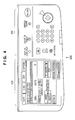
- FIG. 4 is a view for explaining an example of a user interface (UI) to be controlled in the embodiment
- FIG. 5 is a view for explaining an example of the UI to be controlled in the embodiment.
- FIG. 6 is a view for explaining various data stored in a ROM 207 included in the configuration of the printing system 1000 to be controlled in the embodiment;
- FIG. 7 is a view for explaining various data stored in a hard disk 209 (HDD) included in the configuration of the printing system 1000 to be controlled in the embodiment;
- HDD hard disk 209
- FIG. 8 is a view for explaining the structure of job data of a JDF print job processible by the printing system 1000 to be controlled in the embodiment;
- FIGS. 9A and 9B are views for explaining an example of the JDF part of the JDF print job shown in FIG. 8 processible by the printing system 1000 to be controlled in the embodiment;
- FIG. 10 is a view for explaining an example of a device capability information notification request processible by the printing system 1000 to be controlled in the embodiment;
- FIGS. 11A and 11B are views for explaining an example of device capability information processible by the printing system 1000 to be controlled in the embodiment
- FIG. 12 is a table for explaining the internal structure of a mounted option capability table shown in FIG. 6 among various data stored in the ROM 207 included in the configuration of the printing system 1000 to be controlled in the embodiment;
- FIG. 13 is a table for explaining the structure of a device configuration management table stored in a RAM 208 included in the configuration of the printing system 1000 to be controlled in the embodiment;
- FIG. 14 is a first table for explaining the internal structure of a processing rule table 3302 shown in FIG. 7 among various data stored in a hard disk 209 (HDD) included in the configuration of the printing system 1000 to be controlled in the embodiment;
- HDD hard disk 209
- FIG. 15 is a second table for explaining the internal structure of the processing rule table 3302 shown in FIG. 7 among various data stored in the hard disk 209 (HDD) included in the configuration of the printing system 1000 to be controlled in the embodiment;
- HDD hard disk 209
- FIG. 16 is a table for explaining the structure of a JDF analysis result table stored in the RAM 208 included in the configuration of the printing system 1000 to be controlled in the embodiment;
- FIG. 17 is a flowchart for explaining the operation of the overall printing system controlled by a controller 205 of the printing system 1000 to be controlled in the embodiment;
- FIG. 18 is a flowchart for explaining the detailed operation of a device configuration management program in step S 4702 shown in FIG. 17 in the first embodiment
- FIG. 19 is a flowchart for explaining a detailed operation of executing a JDF print job in step S 4710 shown in FIG. 17 in the first embodiment
- FIG. 20 is a flowchart for explaining the detailed operation of JDF part analysis processing in step S 5103 shown in FIG. 19 in the first embodiment
- FIG. 21 is a flowchart for explaining the detailed operation of device configuration change processing in step S 4711 shown in FIG. 17 in the first embodiment
- FIG. 22 is a flowchart for explaining the detailed operation of device capability information notification processing in step S 4712 shown in FIG. 17 in the first embodiment
- FIG. 23 is a flowchart for explaining the detailed operation of JDF part analysis processing in step S 5103 shown in FIG. 19 in the second embodiment;
- FIG. 24 is a block diagram for explaining an example of the hardware configuration of a client computer 104 to be controlled in the third embodiment
- FIG. 25 is a block diagram for explaining an example of the software configuration of the client computer 104 to be controlled in the third embodiment.
- FIG. 26 is a flowchart for explaining a job data transmission operation controlled by a printer control program 2502 of the client computer 104 in the third embodiment.
- the first embodiment can provide a technique of continuing processing after conducting a device capability information test when it cannot be confirmed whether a printing apparatus can process a JDF, upon a change of JDF specifications processible by the printing apparatus. Even for a JDF created while device specifications and configuration information are unknown, processing can continue after performing the device capability information test. This can improve user-friendliness of the device.
- the present embodiment assumes a printing environment such as the POD environment different from the office environment in order to solve the problems described in Description of the Related Art above.
- the embodiment will describe the system environment of the whole POD environment site (printing environment in FIG. 1 ) including a printing system 1000 .
- the embodiment is also applicable to even the printing environment.
- a printing environment to which the printing system 1000 is applicable is suited to even the POD environment and will be called a POD system 10000 .
- the POD system 10000 in FIG. 1 includes, as building components, the printing system 1000 , a server computer 103 (to be also referred to as a PC 103 ), and a client computer 104 (to be also referred to as a PC 104 ).
- the server computer 103 and client computer 104 function as information processing apparatuses.
- the POD system 10000 also includes a paper folding apparatus 107 , sheet cutting apparatus 109 , saddle stitching apparatus 110 , case binding apparatus 108 , and scanner 102 , which function as post-processing apparatuses. In this way, a plurality of apparatuses are available in the POD system 10000 .
- the printing system 1000 includes, as building components, a printing apparatus 100 (main body), and a sheet processing apparatus 200 formed from one or a plurality of apparatuses to function as a post-processing apparatus.
- a printing apparatus 100 the embodiment will exemplify a multifunction peripheral with a plurality of functions such as a copy function and a PC print function of accepting data from a PC to print.
- the printing apparatus 100 may also be a single-function printing apparatus with only the print function or copy function.
- the multifunction peripheral will also be called an MFP.
- the paper folding apparatus 107 , sheet cutting apparatus 109 , saddle stitching apparatus 110 , and case binding apparatus 108 in FIG. 1 are defined as sheet processing apparatuses, similar to the sheet processing apparatus 200 of the printing system 1000 . This is because these devices can execute sheet processes for job sheets (print sheets) printed by the printing apparatus 100 of the printing system 1000 .
- the paper folding apparatus 107 can fold sheets printed by the printing apparatus 100 .
- the sheet cutting apparatus 109 can cut a bundle of sheets printed by the printing apparatus 100 .
- the saddle stitching apparatus 110 can saddle-stitch sheets printed by the printing apparatus 100 .
- the case binding apparatus 108 can case-bind sheets printed by the printing apparatus 100 .
- control unit of the printing system comprehensively controls the printing apparatus 100 and sheet processing apparatus 200 .
- a controller 205 in the printing apparatus 100 in FIG. 2 executes the comprehensive control.
- the aforementioned sheet processing apparatuses will also be called post-processing apparatuses or post-presses.
- All these apparatuses in the POD system 10000 of FIG. 1 except for the saddle stitching apparatus 110 are connected to a network 101 to communicate data with each other.
- the printing apparatus 100 prints print data of a target job which is transmitted via the network 101 from an information processing apparatus serving as an exemplary external apparatus such as the PC 103 or 104 to request execution of printing.
- an information processing apparatus serving as an exemplary external apparatus such as the PC 103 or 104 to request execution of printing.
- the server computer 103 can manage all target jobs in the POD system 10000 (printing environment) by exchanging data with another apparatus by network communication.
- the server computer 103 functions as a computer for comprehensively managing a series of workflow steps including a plurality of processing steps.
- the server computer 103 determines post-processing conditions capable of finishing in the POD system 10000 (printing environment) based on a job instruction accepted from an operator.
- the server computer 103 designates a post-processing (finishing process) step as requested by an end user (customer who requests printing in this case).
- the server computer 103 uses information exchange tools such as JDF to exchange information with respective post-processing devices using commands and statuses in post-presses.
- the server computer 103 can execute, for printed media of a job having undergone print processing by the printing apparatus 100 , various sheet processes such as cutting, saddle stitching, case binding, sheet folding, punching, sealing, and collation.
- a sheet process is possible that comprises a booklet printing style if a booklet is what an end user (customer) wants.
- the server computer 103 manages other types of near-line finishers and offline finishers such as a dedicated stapler, dedicated puncher, inserter, and collator.
- the server computer 103 can grasp device statuses and job statuses from near-line finishers via the network 101 by sequential polling or the like using a predetermined protocol.
- the server computer 103 can also manage the execution statuses (progresses) of many jobs processed in the POD system 10000 (printing environment).
- different sheet processing apparatuses may execute a plurality of print sheet processes, or one sheet processing apparatus may execute many kinds of print sheet processes.
- the system may include any of sheet processing apparatuses.
- the printing system 1000 in FIG. 1 includes the printing apparatus 100 , and the sheet processing apparatus 200 detachable from the printing apparatus 100 .
- the sheet processing apparatus 200 can directly receive, via a sheet conveyance path, job sheets printed by the printing apparatus 100 .
- the sheet processing apparatus 200 executes sheet processing requested by a user together with a print execution request via a user interface for sheets printed by a printer unit 203 of the printing apparatus 100 .
- the internal configuration (mainly software configuration) of the printing system 1000 will be explained with reference to the system block diagram of FIG. 2 .
- the printing apparatus 100 incorporates all the units of the printing system 1000 shown in FIG. 2 except for the sheet processing apparatus 200 (strictly speaking, a group of sheet processing apparatuses configurable by a plurality of inline type sheet processing apparatuses).
- the sheet processing apparatus 200 is detachable from the printing apparatus 100 and can be provided as an option of the printing apparatus 100 .
- This configuration can provide a necessary number (1, 2, . . . , n) of inline finishers necessary in the POD environment.
- the printing apparatus 100 incorporates a nonvolatile memory such as a hard disk 209 (to be also referred to as an “HDD”) capable of storing a plurality of target job data.
- the printing apparatus 100 has a copy function of causing the printer unit 203 to print job data accepted from a scanner unit 201 of the printing apparatus 100 under the control of the controller 205 .
- the printing apparatus 100 also has a print function of causing the printer unit 203 to print job data accepted from an external apparatus such as the PC 103 or 104 via an external I/F 202 serving as an example of a communication unit under the control of the controller 205 .
- the printing apparatus 100 is an MFP type printing apparatus (to be also referred to as an image forming apparatus) having a plurality of functions.
- the printing apparatus can take any configuration of a color or monochrome printing apparatus as long as it can execute a variety of control operations to be described in the embodiment.
- the printing apparatus 100 includes the scanner unit 201 which scans a document image and processes scanned image data.
- the printing apparatus 100 also includes the external I/F 202 which transmits/receives image data to/from a facsimile device, network connection device, or external dedicated device.
- the printing apparatus 100 includes the hard disk 209 (HDD) capable of storing image data of jobs to be printed that are accepted from either the scanner unit 201 or external I/F 202 .
- the printing apparatus 100 includes the printer unit 203 which prints target job data stored in the hard disk 209 (HDD) on a print medium.
- the printing apparatus 100 further includes an operation unit 204 which has a display unit serving as an example of the user interface of the printing system 1000 . Other examples of the user interface provided by the printing system 1000 are the display unit, keyboard, and mouse of an external apparatus such as the PC 103 or 104 .
- a ROM 207 stores a variety of control programs necessary in the embodiment, including programs for executing various processes of flowcharts to be described later.
- the ROM 207 also stores a display control program to display various UI windows on the display unit of the operation unit 204 , including a user interface window (to be referred to as a UI window) shown in FIGS. 4 and 5 .
- the controller 205 reads out programs from the ROM 207 and executes them to cause the printing apparatus to perform various operations to be described in the embodiment.
- the ROM 207 also stores, for example, a program for executing an operation to analyze PDL (Page Description Language) code data received from an external apparatus (e.g., the PC 103 or 104 ) via the external I/F 202 and rasterize it into raster image data (bitmap image data).
- PDL Peage Description Language
- These programs are processed by software.
- the ROM 207 is a read-only memory which stores in advance various programs such as a boot sequence, font information, and the above-mentioned programs.
- a RAM 208 is a readable/writable memory which stores image data, various programs, and setting information sent from the scanner unit 201 or external I/F 202 via the controller 205 .
- the hard disk 209 is a large-capacity storage device which stores image data compressed by a compression/decompression unit 210 .
- the hard disk 209 (HDD) can hold a plurality of data such as print data of a target job.
- the controller 205 controls the printer unit 203 via the hard disk 209 (HDD) to print target job data input via a variety of input units such as the scanner unit 201 and external I/F 202 .
- the controller 205 also controls to transmit job data to an external apparatus via the external I/F 202 . In this fashion, the controller 205 controls to execute various kinds of output processes for target job data stored in the hard disk 209 (HDD).
- the compression/decompression unit 210 compresses/decompresses image data and the like stored in the RAM 208 and hard disk 209 (HDD) in accordance with various compression schemes such as JBIG and JPEG.
- the controller 205 serving as an example of the control unit of the printing system controls even the operation of the inline type sheet processing apparatus 200 , as shown in FIG. 1 .
- the hardware configuration of the printing system 1000 including a description of this operation will be explained with reference to FIG. 3 .
- the configuration (mainly hardware configuration) of the printing system 1000 will be explained with reference to the view of FIG. 3 for explaining the apparatus configuration.
- a hardware configuration will be explained with reference to an example wherein the printing apparatus 100 executes print processing before sheet processing is to be executed by the inline type sheet processing apparatuses 200 .
- a paper handling operation before supplying printed job sheets from the printer unit 203 into the sheet processing apparatus 200 will be mainly explained.
- the controller (to be also referred to as a control unit or CPU hereinafter) 205 in FIG. 2 causes the printing apparatus 100 to execute this operation.
- reference numeral 301 corresponds to the hardware configuration of the scanner unit 201 in FIG. 2 .
- Reference numerals 302 to 322 correspond to the hardware configuration of the printer unit 203 in FIG. 2 .
- the embodiment will describe the structure of a 1 D (Drum) color MFP.
- a 4 D (Drum) color MFP and monochrome MFP are also examples of the printing apparatus in the embodiment, but a description thereof will be omitted.
- the auto document feeder (ADF) 301 in FIG. 3 separates a document bundle set on the support surface of a document tray in page order from the first page, and feeds each document sheet to an original plate to scan it by the scanner 302 .
- the scanner 302 scans the image of the document sheet fed onto the original plate, and converts it into image data by a CCD.
- the rotating polygonal mirror (e.g., polygon mirror) 303 receives a light ray (e.g., a laser beam) modulated in accordance with the image data, and irradiates the photosensitive drum 304 with the scan beam reflected by a reflecting mirror.
- a latent image formed by the laser beam on the photosensitive drum 304 is developed with toner, and the toner image is transferred onto a sheet material adhered onto the transfer drum 305 .
- a series of image forming processes is executed sequentially with yellow (Y), magenta (M), cyan (C), and black (K) toners, forming a full-color image.
- the sheet material bearing the full-color image on the transfer drum 305 is separated by the separation gripper 306 , and conveyed to the fixing unit 308 by the pre-fixing conveyor 307 .
- the fixing unit 308 is formed from a combination of rollers and belts, and incorporates a heat source such as a halogen heater.
- the fixing unit 308 fuses and fixes, by heat and pressure, toner on a sheet material bearing a toner image.
- the discharge flapper 309 can swing about the swing shaft, and regulates the sheet material conveyance direction. When the discharge flapper 309 swings clockwise in FIG. 3 , a sheet material is conveyed straight and discharged from the apparatus by the discharge rollers 310 . When forming images on the two surfaces of a sheet material (i.e. both sides of a sheet of paper), the discharge flapper 309 swings counterclockwise in FIG. 3 to change the course of the sheet material to downwards. Then, the sheet material is supplied to a double-sided conveyor.
- the double-sided conveyor includes the reversing flapper 311 , reversing rollers 312 , reversing guide 313 , and double-sided tray 314 .
- the reversing flapper 311 can swing about a swing shaft, and regulates the sheet material conveyance direction.
- the controller 205 controls the reversing flapper 311 to swing counterclockwise in FIG. 3 and supply a sheet with the first surface printed by the printer unit 203 to the reversing guide 313 via the reversing rollers 312 . While the reversing rollers 312 clamp the trailing end of the sheet material, the reversing rollers 312 temporarily stop.
- the reversing flapper 311 swings clockwise in FIG. 3 , and the reversing rollers 312 rotate back. As a result, the sheet is switched back to replace its trailing and leading ends. Then, the sheet is guided to the double-sided tray 314 .
- the double-sided tray 314 temporarily supports the sheet material, and re-feed roller 315 supplies the sheet material again to registration rollers 316 .
- the sheet material is sent with a surface opposite to the first surface in the transfer step facing the photosensitive drum.
- the second image is formed on the second surface of the sheet.
- the sheet is discharged from the printing apparatus main body via the discharge rollers 310 after a fixing process.
- the controller 205 executes this double-sided print sequence.
- the printing apparatus can therefore execute double-sided printing of target job data on the first and second surfaces of a sheet.
- the sheet feed/conveyance section includes: the paper cassettes 317 and 318 (each capable of storing, for example, 500 sheets) serving as paper feed units for storing sheets necessary for print processing; the paper deck 319 (capable of storing, for example, 5,000 sheets); and the manual feed tray 320 .
- Units for feeding sheets from these paper feed units are the paper feed rollers 321 , registration rollers 316 , and the like.
- the paper cassettes 317 and 318 and the paper deck 319 allow setting sheets of various materials at various sheet sizes discriminately in the respective paper feed units.
- the manual feed tray 320 also allows the setting of various kinds of print media including a special sheet such as an OHP sheet.
- the paper feed rollers 321 are arranged in the paper cassettes 317 and 318 , paper deck 319 , and manual feed tray 320 , respectively.
- the paper feed roller 321 can successively feed sheets one by one. For example, a pickup roller picks up stacked sheet materials sequentially. While a separation roller facing the paper feed roller 321 prevents double feed, the sheet materials are supplied one by one to the conveyance guide.
- the separation roller receives a driving force via a torque limiter (not shown) to rotate the separation roller in a direction opposite to the conveyance direction. When only one sheet material enters a nip formed between the separation roller and the paper feed roller, the separation roller rotates in the conveyance direction following the sheet material.
- the separation roller rotates in a direction opposite to the conveyance direction to set back the double-fed sheet material and supply only one top sheet material.
- the supplied sheet material is guided between the conveyance guides and conveyed to the registration rollers 316 by a plurality of conveyance rollers.
- the registration rollers 316 stop, and the leading end of the sheet material abuts against the nip formed between a pair of registration rollers 316 .
- the sheet material forms a loop to correct a skew.
- the registration rollers 316 start rotating to convey the sheet material in synchronism with the timing to form a toner image on the photosensitive drum 304 in the image forming section.
- An attraction roller 322 electrostatically attracts the sheet material sent by the registration rollers 316 onto the surface of the transfer drum 305 .
- the sheet material discharged from the fixing unit 308 is introduced into the sheet conveyance path in the sheet processing apparatus 200 via the discharge rollers 310 .
- the controller 205 processes a job consisting of printing.
- the controller 205 causes the printer unit 203 by the above-described method to print job print data stored in the hard disk 209 (HDD).
- the job print data comes from a data generation source in response to a print execution request accepted from a user via the UI.
- the data generation source of a job may be the scanner unit 201 and a print execution request may be received from the operation unit 204 .
- the data generation source of a job, to which a print execution request is accepted from a host computer, means the host computer.
- the controller 205 stores print data of a target job sequentially from the first page onwards in the hard disk 209 (HDD).
- the controller 205 reads out the print data of the job from the hard disk 209 (HDD) in order from the first page, and forms the image of the print data on a sheet.
- the controller 205 supplies sheets printed sequentially, from the first page to the n th page, to the sheet conveyance path in the sheet processing apparatus 200 with the image surfaces of the sheets facing downwards.
- the controller 205 executes a switchback operation using the discharge flapper 309 and reversing rollers 312 , etc. to reverse the sheet travelling from the fixing unit 308 .
- the printing system 1000 in the embodiment includes a total of n inline type sheet processing apparatuses 200 cascade-connectable to the printing apparatus 100 .
- the number of installed inline sheet processing apparatuses is flexible.
- the present invention aims at improving user-friendliness and is not an essential constituent feature.
- the present invention should not be interpreted restrictively to the above-described arrangement.
- the present invention may adopt a system configuration in which the number of inline sheet processing apparatuses available in the printing system 1000 and the connection order of these apparatuses are fixed.
- the present invention includes any system configurations and apparatus arrangements as long as the system can execute at least one of various job control operations to be described later.
- the operation unit 204 serving as an example of the user interface (to be referred to as a UI) of the printing apparatus 100 in the printing system 1000 will be explained with reference to FIGS. 4 and 5 .
- the operation unit 204 includes a key input section 402 capable of accepting a user operation with hard keys, and a touch panel section 401 serving as an example of a display unit capable of accepting a user operation with soft keys (display keys).
- the key input section 402 includes an operation unit power switch 501 .
- the controller 205 controls the apparatus to cause it selectively to switch between the standby mode and the sleep mode.
- the standby mode is a normal operation state.
- the sleep mode is a state in which power consumption is suppressed by stopping programs, causing them to wait for an interruption by network printing, facsimile transmission, or the like.
- the controller 205 controls the apparatus to cause it to accept a user operation of the operation unit power switch 501 while a main power switch (not shown) for supplying power to the whole system is ON.
- a start key 503 enables the acceptance of an instruction from a user to cause the printing apparatus to start a job processing designated by that user, such as copying or transmission of a target job.
- a stop key 502 enables the acceptance of an instruction from the user to cause the printing apparatus to suspend the processing of an accepted job.
- a ten-key pad 506 allows the user to set the entries of various settings.
- a clear key 507 is used to cancel various parameters such as entries set by the user via the ten-key pad 506 .
- a reset key 504 is used to accept, from the user, an instruction to invalidate various settings made by the user to a target job and restore the set values to defaults.
- a user mode key 505 is used to shift to a system setup window for each user.
- the controller 205 executes the following exemplary control in the printing system 1000 having the above-described system configuration with an eye toward the POD market.
- FIG. 6 exemplifies a variety of programs which are stored in the ROM 207 in FIG. 2 , and read out and executed by the controller 205 in the printing system 1000 , and data used by the programs and the like.
- the ROM 207 stores programs for implementing various functions which can be provided by the printing system 1000 .
- a boot loader 3101 is a program executed immediately when the printing system 1000 is turned on.
- the boot loader 3101 is a program for executing various startup sequences necessary to start up the system.
- An operating system 3102 provides an execution environment for various programs which implement the functions of the printing system 1000 .
- the operating system 3102 mainly provides a function of managing the memory resource of the printing system 1000 , and a function of performing basic input/output control of a variety of devices shown in FIG. 6 .
- the memory of the printing system 1000 includes, for example, the ROM 207 , RAM 208 , and hard disk 209 in FIG. 2 .
- a data transmission/reception program 3103 is a control program to perform transmission/reception processing upon receiving a data input/output request via the external I/F 202 in FIG. 2 . More specifically, the data transmission/reception program 3103 is a control program which contains a protocol stack such as TCP/IP and controls communication of various data with a connected external device or the like via the network 101 in the POD system 10000 (printing environment) shown in FIG. 1 .
- This communication processing is specialized in communication processing in an HTTP server and at the transmission/reception level of data packets input/output between the printing system 1000 and the network 101 .
- the communication processing does not include processing to analyze received data contents, which will be described later.
- the controller 205 executes the data analysis processing based on the description contents of another program, which will be described later.
- a device management function program 3104 integrally manages the connection states, statuses, and capabilities of various devices, the devices being managed by the printing system 1000 to implement the functions of the MFP. These devices include detachable and non-detachable devices such as the printer unit 203 , scanner unit 201 , and sheet processing apparatus 200 .
- the device management function program 3104 runs when the controller 205 activates the system or is notified of a change of the state of a connected device.
- a copy function program 3105 causes the controller 205 to execute the copy function in accordance with an instruction from the operation unit 204 when the user designates execution of the copy function via the operation unit 204 .
- a scan function program 3106 causes the controller 205 to execute the scan function in accordance with an instruction from the operation unit 204 when the user designates execution of the scan function via the operation unit 204 .
- a PDL print function program 3107 causes the controller 205 to execute the PDL print function in accordance with an instruction from the operation unit 204 upon receiving PDL print job data via the external I/F 202 .
- a JDF print function program 3108 causes the controller 205 to execute the JDF print function in accordance with an instruction from the operation unit 204 upon receiving JDF-containing job data via the external I/F 202 .
- the controller 205 controls the apparatus to cause it to execute JDF print processing by sequentially instructing device resources in the printing system 1000 .
- the sequential instructions are for the execution of operations in an appropriate order based on a processing order and processing conditions described in the JDF print function program 3108 .
- the device resources for executing the JDF print function include, for example, the sheet processing apparatus 200 , printer unit 203 , hard disk 209 (HDD), compression/decompression unit 210 , and RAM 208 .
- a BOX function program 3109 causes the controller 205 to execute a BOX function in accordance with an instruction from the operation unit 204 when the user of the printing system 1000 designates execution of the BOX function via the operation unit 204 .
- a UI control program 3110 is a control program for the touch panel section 401 and key input section 402 of the operation unit shown in FIGS. 4 and 5 when the printing system is completely activated and can provide the functions of the MFP.
- Another control program 3111 implements functions not supported by any of the above-described programs, and executes various operations. However, details of the control program 3111 are not important for describing the effects of the embodiment, and a description thereof will be omitted.
- a mounted option capability table 3112 is table information which statically holds device information of apparatuses detachable from the printing system 1000 .
- the ROM 207 stores the device information so that the controller 205 in the printing system 1000 refers to it to perform processing to, for example, change processing contents in accordance with the capability of a mounted option when executing various jobs or managing devices.
- the table is named a mounted option capability table.
- Mounted options are not limited to apparatuses designed to be detachable, like a large-volume stacker, glue binding apparatus, and saddle stitching apparatus.
- this table may manage the printing apparatus 100 and the scanner of the printing apparatus 100 as special mounted options.
- the embodiment will describe a case in which a single table manages information on the printing apparatus 100 similarly to detachable apparatuses.
- FIG. 7 exemplifies the storage status of various data which are stored in the hard disk 209 in FIG. 2 , and read out or written by the controller 205 in the printing system 1000 .
- Information stored in the hard disk 209 dynamically changes depending on the device use status, device configuration, and job progress, unlike the internal state of the ROM 207 shown in FIG. 6 .
- FIG. 7 shows a state of the data stored in the hard disk 209 at a time when the printing system 1000 is running.
- the internal state of the hard disk 209 is not always the same as that in FIG. 7 .
- a free area 3306 shown in FIG. 7 may contain some of the data of the large-volume print jobs, changing the free capacity within it.
- the device management information area 3301 stores information such as the connection state of the sheet processing apparatus 200 detachable from the printing system 1000 , and the connection state, status, and capability of an optional device that depends on the configuration of the printing system 1000 .
- the device management information 3301 stores a valid device capability information ID uniquely representing information such as the connection state, status, and capability of a current device.
- the valid device capability information ID may be binary data expressing the contents of the device management information 3301 or the update date and time of the device management information 3301 .
- the valid device capability information ID is used to determine whether a client computer has created a JDF based on the latest device capability information.
- the device management function program 3104 shown in FIG. 6 manages the device management information 3301 . Information stored and managed in the device management table will be described later. When and how the controller 205 uses information in this table will also be described later.
- a processing rule table 3302 describes operation specifications concerning the operation of a device when the printing system 1000 tries to process a JDF print job but cannot physically execute it at job settings owing to the device configuration, device capability, or the like. Information stored in the processing rule table 3302 will be described later. When and how the controller 205 uses information in this table will also be described later. Job execution control based on the processing rule table is not limited to a JDF print job. It is also possible to define a processing rule table concerning another job type, and execute a job of this type similarly to the JDF print job. The embodiment targets only the JDF print job for descriptive convenience.
- Saved document data 3303 corresponds to document data held in the printing system using the BOX function provided by the BOX function program 3109 shown in FIG. 6 .
- a following saved document data management table 3304 holds management information of the saved document data 3303 .
- a spool area 3305 temporarily holds print data transmitted to the printing system 1000 until the completion of executing the job.
- the print data includes one transmitted by the PDL print function provided by the PDL print function program 3107 shown in FIG. 6 , or one transmitted by the JDF print function provided by the JDF print function program 3108 .
- the print job data is deleted from the spool area 3305 to free the area for a subsequent print job.
- the controller 205 controls the hard drive to cause it to store data in the spool area 3305 and free the spool area 3305 upon completion of the job while executing the PDL print function and JDF print function.
- the free area 3306 corresponds to an area in the hard disk 209 left over after all the areas described above have been allocated for storage. The capacity of this area changes along with the progress of processing in the printing system 1000 .
- the free area 3306 may run out and disappear depending on the use load of the hard disk 209 .
- FIG. 8 exemplifies the structure of job data to be processed by the JDF print function provided by the JDF print function program 3108 shown in FIG. 6 .
- a JDF print job is based on the premise that the following components are assembled into a single package in a MIME format. The following data encoded in the MIME format is accepted:
- JDF print function in the embodiment also assumes processing of job data in the MIME format.
- JDF specifications refer to handling of job data other than a MIME package.
- data packaging specifications are not essential for describing the effects of the embodiment, so job data of the MIME format will be explained.
- a MIME header 3501 is a header area always necessary when assembling a plurality of parts into a single package in the MIME format.
- the MIME header 3501 stores MIME management information such as the total data size of the MIME package.
- a JMF part 3502 is an area storing the above-mentioned management information for communication and status management between POD workflows.
- JMF Job Messaging Format which is the format of messages exchanged between processes and devices in a JDF workflow.
- a JDF part 3503 is an area holding the aforementioned job setting information.
- a JDF specification form issued by CIP 4 as JDF specifications describes setting information held in JDF and the format of the setting information.
- the JDF print function in the printing system 1000 is assumed to be implemented based on matters described in the specification form, and a detailed description thereof will be omitted. As a minimum example for describing the effects of the embodiment, an example of the JDF is shown in drawings subsequent to FIG. 8 , and its outline will be explained later.
- a PDL file 1 3504 , PDL file 2 3505 , and PDL file 3 3506 are content data to be printed.
- the MIME package contains three content data.
- the specifications do not limit the number of PDL content parts, and the same processing applies to even more than the three contents of FIG. 8 .
- PDL contents are held not in the MIME package but in an external file system or the like.
- the JDF describes only the URL of the file held in the external file system or the like.
- Some specifications designate processing content data by pulling a file held in the external file system or the like based on the URL.
- the JDF print function in the printing system 1000 can also process this function. Since the basic operation is the same, details of the content file pulling operation will not be described in the embodiment.
- the specifications of the MIME format are defined by RFC (Request for Comments), and a detailed description thereof will be omitted.
- FIGS. 9A and 9B show an example of the JDF description contents of the JDF part 3503 in the MIME package in FIG. 8 .
- the JDF shown in FIGS. 9A and 9B is merely a specific example of the JDF description based on JDF specifications, and the JDF description is not limited to it.
- the exemplary JDF shown in FIGS. 9A and 9B merely contains minimum contents to efficiently describe the following functions.
- the JDF part shown in FIGS. 9A and 9B is mainly made up of the following four parts:
- information stored in the JDF node 3701 contains a device management information ID stored in device capability information referred to by a client computer to create a JDF.
- the device management information ID is used to determine device capability information used by a client computer to create a JDF.
- an attribute refDevCapID corresponds to the device management information ID.
- Each part has specifications, described contents, schema, etc., compliant with JDF specifications.
- the JDF specifications are described in the JDF specification form, so details thereof will not be described in the embodiment of the present invention.
- FIG. 10 is a view showing a specific example of a device capability information notification request received by the I/F 202 from an external device.
- Device capability information shown in FIG. 10 is a specific example of a device capability information description based on JDF specifications, and the device capability information is not limited to it.
- the exemplary device capability information shown in FIG. 10 has minimum contents to efficiently describe the following functions.
- the device capability information notification request shown in FIG. 10 is roughly formed from the following two parts:
- JDF JDF specifications
- JDF specifications are described in the JDF specification form, so details thereof will not be described in the embodiment of the present invention.
- the device management function program 3104 shown in FIG. 6 implements the device management function.
- FIGS. 11A and 11B show an example of the description contents of device capability information generated by the device management function as a result of executing the device management function program 3104 .
- the device capability information shown in FIGS. 11A and 11B is a specific example of a device capability information description based on JDF specifications, and the device capability information is not limited to it.
- the exemplary device capability information shown in FIGS. 11A and 11B has minimum contents to efficiently describe the following functions.
- the device capability information shown in FIGS. 11A and 11B is roughly formed from the following two parts:
- information stored in the device capability node 3722 contains a device management information ID.
- the device management information ID is used to determine device capability information used by a client computer to create a JDF.
- an attribute DevCapID corresponds to the device management information ID.
- Each part contains specifications, described contents, schema, etc. compliant with JDF specifications.
- the JDF specifications are described in the JDF specification form, so details thereof will not be described in the embodiment of the present invention.
- FIG. 12 is a table for explaining details of information stored and managed in the mounted option capability table 3112 shown in FIG. 6 .
- the mounted option capability table 3112 is made up of four fields, and pieces of information in the four fields are managed and stored for each connected device.
- a device type field 3901 is used to identify the type of sheet processing apparatus 200 mountable in the printing system 1000 and the type of detachable device such as the paper deck 319 shown in FIG. 3 .
- the main body of the printing apparatus 100 is not a mounted option.
- the printing apparatus 100 is regarded as a special mounted option for easy management by a single table and managed in this table. If mounted options and the printing apparatus 100 is to be discriminated and managed exactly, the table shown in FIG. 12 is divided into two to manage them. However, the embodiment will not exemplify this case. In the description of FIG. 12 , both detachable devices and the printing apparatus 100 will be referred to as a device altogether.
- a category field 3902 stores a category to which a device described in the device type field 3901 belongs.
- the following categories can be defined as ones to be stored, and the category field 3902 stores one of them:
- the printing system 1000 includes the paper cassettes 317 and 318 , as shown in FIG. 3 .
- the mounted option capability table 3112 is managed such that each device is always classified into one of the four categories.
- a function field 3903 stores the types of functions provided by a device. Since functions by a device change depending on the category to which the device belongs, the contents of the table in FIG. 12 reflect them. In other words, the mounted option capability table 3112 is managed such that devices belonging to the same category have the same set of function fields.
- a support status field 3904 holds flag information representing whether each device can implement a function described in the function field 3903 .
- Possible values are a value meaning OK when the device supports the function, and a value meaning UNSUPPORTED when it does not support the function.
- Data in the mounted option capability table 3112 in FIG. 6 stored in the ROM 207 is a specific binary numerical value.
- the character string “OK” or “UNSUPPORTED” itself shown in FIG. 12 is not stored.
- the embodiment adopts the expressions “OK” and “UNSUPPORTED” as values equivalent to binary numerical values as if the character string “OK” or “UNSUPPORTED” were stored. This expression merely aims at easy understanding of the embodiment. In the following description of the embodiment, the same description method applies to a value stored in the table.
- the mounted option capability table 3112 shown in FIG. 12 stores information on five types of devices.
- the five types of devices are an MFP main body 3905 , large-volume paper deck 3906 , large-volume stacker 3907 , glue binding apparatus 3908 , and saddle stitching apparatus 3909 .
- the glue binding apparatus and saddle stitching apparatus belong to the same category “finisher”, as shown in FIG. 12 .
- FIG. 13 is a table for explaining the contents of a device configuration management table.
- the device configuration management table is managed by the device management function program 3104 shown in FIG. 6 , and held (stored) in the RAM 208 according to the method and conditions described with reference to the device management function program 3104 in FIG. 6 .
- the device configuration management table manages the connection states of the detachable sheet processing apparatus 200 installed in the printing system 1000 , the paper deck 319 shown in FIG. 3 , a subdevice of the printing apparatus 100 , and the like. This table is made up of three fields, which will be described below.
- a device name field 4101 lists all devices detachable from the printing system 1000 . When devices of the same type are attachable, they are managed distinctively with (alphanumerical) figures added to the end of their device names.
- the printing system 1000 allows selecting a complicated combination of options to meet a user need. However, not all devices can always be combined depending on their types, and some combinations are impossible owing to the physical or device configuration, as described above.
- the device name field 4101 shown in FIG. 13 does not manage the validity of each combination, and only lists all devices which may be installed in the printing system 1000 . Whether each device is actually mounted is indicated by a value in another field (connection state—see later) of this table.
- a device type field 4102 stores the category of a device described in the device name field 4101 .
- the device type field 4102 stores a value equivalent to the contents of the category field 3902 in the mounted option capability table shown in FIG. 12 .
- a connection state field 4103 stores whether a device described in the device name field 4101 is connected to the printing apparatus.
- a possible value is a value meaning OK when a device described in the device name field 4101 that supports a target function is connected to the printing apparatus.
- Another possible value is a value meaning not connected when a device described in the device name field 4101 is not connected to the printing apparatus.
- one scanner and one large-volume stacker are connected in the printing system 1000 .
- FIG. 14 is a table for explaining the detailed contents of information stored in the processing rule table 3302 which is stored in the hard disk 209 and has already been described with reference to FIG. 7 . As shown in FIG. 14 , this table is made up of three fields, which will be described below.
- a function field 4301 holds the type of setting attribute of a function necessary to execute a job settable by a JDF.
- 16 different setting items are registered.
- the number of setting items processible by an actual JDF print job is larger than that shown in FIG. 14 .
- only limited types of setting attributes will be exemplified for descriptive convenience, and the effects of the embodiment will be explained based on them.
- An operation specification field 4302 in the case of not supporting a designated function describes the contents of processing which should be employed when the printing system 1000 cannot execute a designated function and the controller 205 is to execute a JDF print job input to the printing apparatus.
- the operation specification field 4302 stores a value corresponding to operation designation information which designates an operation performed when the printing apparatus cannot provide a print function necessary to satisfy designated printing conditions. This field takes the following three values:
- the system sets in advance a value in the operation specification field in the case of not supporting a designated function that corresponds to each function described in the function field 4301 .
- the system may allow the user to change a value in this field.
- a default value field 4303 in FIG. 14 stores a default value selected when the “operation specification in the case of not supporting a designated function” field 4302 takes the value “operate at a default value”. When the operation specification field 4302 takes another value, the field 4303 is blank.
- FIG. 15 shows a case in which all values in the operation specification field 4302 in the case of not supporting a designated function are set to “cancel job” as an operation performed when functions described in the function field 4301 cannot be executed due to the device configuration or capability, etc. of the printing system 1000 in FIG. 14 .
- Job cancellation processing is done according to the description contents of the processing rule table when the JDF designates a non-executable function while the processing rule table stores information shown in FIG. 15 .
- processing to continue or cancel a job when the JDF designates a non-executable function can be controlled.
- FIG. 16 is a table for explaining details of a JDF analysis result table generated upon completion of analyzing the JDF part 3503 in job data shown in FIG. 8 when a JDF print job is input.
- the JDF print job is input via the external I/F 202 connected to an external device, based on processing of the JDF print function program 3108 which is stored in the hard disk 209 and executed by the controller 205 in FIG. 2 .
- this table is made up of three fields, which will be described below.
- a function field 4501 stores the type of setting attribute of each function that is turned out as a result of analyzing a JDF.
- An analysis result field 4502 stores the analysis result of a JDF in accordance with the type in the function field 4501 .
- An execution possible/impossible field 4503 stores a result of determining, for each setting item, whether to continuously execute a JDF print job by collating the analysis result of each function with the function field of the processing rule table by the controller 205 .
- a value is set in the execution possible/impossible field 4503 upon completion of JDF part analysis processing.
- the analysis result of each function is stored in, for example, the analysis result field 4502 .
- FIG. 14 exemplifies the processing rule table.
- the execution possible/impossible field 4503 takes the following three values:
- the JDF analysis result table shown in FIG. 16 is an example generated when the JDF exemplified in FIGS. 9A and 9B is analyzed while the device configuration management table shown in FIG. 13 is in a state shown in FIG. 13 .
- the JDF in FIGS. 9A and 9B designates execution of center folding by saddle stitching, but the device configuration management table shown in FIG. 13 shows that a finisher capable of executing center folding is not mounted.
- the value is “cancel job” in the operation specification field in the case of not supporting the saddle stitching function in the processing rule table shown in FIG. 14 .
- the value in the execution possible/impossible field for the saddle stitching function in FIG. 16 is UNSUPPORTED. That is, when the printing system 1000 has a configuration and state shown in FIG. 13 , a JDF print job containing the JDF exemplified in FIGS. 9A and 9B is not executed but canceled.
- FIG. 17 is a flowchart for explaining a processing sequence concerning control of the overall system serving as an MFP after the controller 205 in FIG. 2 activates the system.
- step S 4701 the system is booted (step S 4701 ). More specifically, the controller 205 reads out the boot loader 3101 shown in FIG. 6 from the ROM 207 and executes the readout program. Processes in this step include execution of all initialization processes such as issuing of initialization commands to various devices and resources, etc. connected to the printing system, and cleaning performed immediately after devices are activated. Processes performed by the boot loader 3101 also include a process to read out the operating system 3102 ( FIG. 6 ) from the HDD 209 (HDD) by the controller 205 and start the services of the operating system.
- the operating system 3102 FIG. 6
- HDD HDD 209
- the controller 205 Upon completion of the boot processing, the controller 205 reads out the device management function program 3104 from the ROM 207 and executes it (step S 4702 ). According to the device management function program 3104 executed in this step, the controller 205 checks the device connection state and creates the device configuration management table shown in FIG. 13 in the RAM 208 . Details of the operation in step S 4702 will be described later with reference to FIG. 18 .
- step S 4703 the controller 205 reads out other programs from the ROM 207 and executes them.
- various programs in FIG. 6 stored in the ROM are loaded except for those which have already been loaded in the preceding steps, but details thereof will be omitted.
- step S 4703 all preparations for the printing system 1000 to function as an MFP are complete, and the process shifts to step S 4704 to wait for an event.
- the event includes any of the following:
- controller 205 which controls the whole printing system does not shift from step S 4704 unless an event occurs.
- step S 4704 If any event occurs in the printing system 1000 and the controller 205 is notified of it in step S 4704 , the process advances to step S 4705 and subsequent steps.
- the controller 205 identifies the generated event and executes an operation corresponding to it.
- step S 4705 the controller 205 determines the type of event generated in step S 4704 . Based on the result of the determination in step S 4705 upon generation of the event, the controller 205 determines whether the generated event is a JDF job execution start request.
- the JDF job execution start request is an event issued to the controller 205 when it is determined that the I/F unit 202 in FIG. 2 has received JDF job data from an external device. If the controller 205 determines in step S 4706 that the generated event is the JDF job execution start request (YES in step S 4706 ), the process advances to step S 4710 . If the controller 205 determines in step S 4706 that the generated event is not the JDF job execution start request (NO in step S 4706 ), the process advances to step S 4707 .
- step S 4710 the controller 205 executes print processing of the JDF print job input from the external device to the printing system 1000 via the external I/F 202 . Details of the operation in step S 4710 will be described later with reference to FIG. 19 .
- step S 4706 determines whether the event determined in step S 4705 is not the JDF job execution start request (NO in step S 4706 ).
- the process advances to step S 4707 .
- step S 4707 the controller 205 determines whether the generated event is a change of the device configuration (third determination step).
- step S 4707 at least one of a change of the device configuration, a change of available print media, a change of the remaining amount of consumables, and a change of the device operation state is detected as a change of a function processible by the printing system.
- step S 4707 determines in step S 4707 that the generated event is a change of the device configuration (YES in step S 4707 ).
- the process advances to step S 4711 to execute device configuration change processing. Details of the device configuration change processing will be described later with reference to FIG. 21 .
- step S 4707 determines whether the generated event is a device capability information notification request.
- the device capability information notification request is an event issued to the controller 205 when, for example, it is determined that the I/F 202 in FIG. 2 has received the device capability information notification request from an external device. If the controller 205 determines in step S 4708 that the generated event is the device capability information notification request (YES in step S 4708 ), the process advances to step S 4712 to execute device capability information notification processing. Details of the device capability information notification processing will be described later with reference to FIG. 22 .
- step S 4708 the controller 205 executes processing corresponding to the type of generated event except for execution of the JDF job or the device configuration change processing.
- step S 4709 the controller 205 executes processing corresponding to the type of generated event except for execution of the JDF job or the device configuration change processing.
- processes of various contents may be executed. However, the type and contents of each operation are not important for a description of the embodiment, so these operations are described as a single step. However, this step includes execution of a plurality of processes, as described above.
- step S 4709 After the controller 205 completes the processes in steps S 4709 , S 4710 , S 4711 , and S 4712 , the process moves to step S 4704 , and the controller 205 waits again for the next event processing.
- FIG. 18 is a flowchart for explaining the detailed operation of the device configuration management program executed by the controller 205 in step S 4702 shown in FIG. 17 .
- the controller 205 creates the entry of the device configuration management table in the RAM 208 .
- the device configuration management table has already been described in detail with reference to FIG. 13 , and a description thereof will not be repeated.
- the device configuration management table created in step S 4901 stores information in only the device name field 4101 and device type field 4102 , and the connection state field 4103 is blank.
- step S 4902 and subsequent steps correspond to processing to store an appropriate value in the connection state field 4103 .
- step S 4902 as the first step of this processing, the controller 205 determines whether all devices registered in the device name field 4101 of the device configuration management table have been checked. When the process reaches step S 4902 immediately after step S 4901 , the determination result in step S 4902 is always NO.
- step S 4902 determines in step S 4902 that a device to be checked still remains (NO in step S 4902 )
- the process advances to step S 4903 to select an inquiry target device.
- devices are selected in order of device names in the device name field 4101 of the device configuration management table created in step S 4901 .
- step S 4904 determines in step S 4904 whether the device selected in step S 4903 is connected to the printing system 1000 .
- the connection state is confirmed in accordance with a specific protocol via a connection unit for electrically connecting devices, a detailed description of which will be omitted.
- the controller 205 receives a status to this effect and confirms the connection. To the contrary, if no response is sent back to an output inquiry request within a predetermined period and a time-out occurs, the controller 205 determines that the inquiry target device is not connected.
- step S 4905 the controller 205 determines the inquiry result of step S 4904 . If the controller 205 determines that the inquiry target device is connected (YES in step S 4905 ), the process advances to step S 4906 to update the status of the device in the connection state field 4103 of the device configuration management table to “OK”. If the controller 205 determines that no inquiry target device is connected (NO in step S 4905 ), the process advances to step S 4907 to update the status of the device in the connection state field 4103 of the device configuration management table to “not connected”.
- step S 4906 or S 4907 Upon completion of the processing in step S 4906 or S 4907 , the process returns to step S 4902 again to check the next device. Steps S 4902 to S 4906 and S 4907 form a loop, and these steps are iteratively executed until the completion of checking all devices described in the device name field 4101 of the device configuration management table.
- step S 4902 determines in step S 4902 that the connection states of all devices have been checked (YES in step S 4902 )
- the process advances to step S 4908 to update a valid device capability information ID stored in the device management information 3301 . After that, the sequence in FIG. 18 ends.
- FIG. 19 is a flowchart for explaining a detailed sequence in step S 4710 shown in FIG. 17 , that is, when the controller 205 executes print processing of a JDF print job input to the printing system 1000 .
- the controller 205 analyzes the MIME format of data building a JDF print job in step S 5101 . More specifically, the controller 205 extracts contents from received MIME data based on MIME header information (division into parts), and stores the extracted contents in the hard disk 209 . In this step, contents extracted from MIME data are three types: JMF, JDF, and PDL contents to be printed.
- the MIME format permits the presence of one or more PDL contents.
- step S 5102 to analyze the JMF part which has been extracted from the MIME data in step S 5101 and is stored in the hard disk 209 .
- the JMF itself is important in managing communication, status, and the like when the JDF workflow system is controlled.
- the JMF is not important in describing the effects of the embodiment, so a detailed description thereof will be omitted.
- step S 5103 Upon completion of the JMF part analysis processing in step S 5102 , the process advances to step S 5103 to analyze the JDF part which has been extracted from the MIME data in step S 5101 and is stored in the hard disk 209 . Detailed processing in step S 5103 will be described later with reference to FIG. 20 .
- the controller 205 In the JDF analysis processing in step S 5103 , the controller 205 also determines whether the received job can be executed, based on setting information described in the JDF, and the device capability and status.
- step S 5104 based on setting information described in the JDF determined in step S 5103 , and the device capability and status, the controller 205 determines whether the received job can be executed, and decides subsequent processing. If the controller 205 determines in step S 5104 that the received job can be executed (YES in step S 5104 ), the process advances to step S 5105 . If the controller 205 determines in step S 5104 that the received job cannot be executed (NO in step S 5104 ), the process advances to step S 5107 .
- step S 5105 the controller 205 analyzes PDL contents which have been extracted from the MIME data in step S 5101 and which are to be printed. More specifically, the controller 205 analyzes a PDL command and converts it into image data in accordance with the setting information described in the JDF analyzed in step S 5103 . The controller 205 finally converts the image data into a printable raster image, and stores the converted image data in the hard disk 209 . Details of the PDL data analysis processing are not important in describing the effects of the embodiment, so a detailed description thereof will be omitted.
- step S 5106 according to the setting information described in the JDF analyzed in step S 5103 , the controller 205 prints the image data which have been rasterized in step S 5105 and is stored in the hard disk 209 . That is, the controller 205 performs print processing based on the JDF analysis result table as exemplified in FIG. 16 .
- print functions necessary to satisfy printing conditions designated in the JDF a function which can be provided as designated by the printing system is executed.
- an operation based on the operation specification field 4302 in the case of not supporting the function is executed.
- the configuration according to the embodiment can therefore execute appropriate print processing using functions which can be provided by the printing system.
- step S 5106 After the end of the processing in step S 5106 , the process returns to step S 4704 in FIG. 17 .
- step S 5104 determines in step S 5104 that the received job cannot be executed, it cancels execution of the job in step S 5107 .
- step S 5107 the process returns to step S 4704 in FIG. 17 (as shown by the reference numeral “A”).
- FIG. 20 is a flowchart for explaining details of the operation in step S 5103 of FIG. 19 , that is, the JDF part analysis processing.
- the controller 205 analyzes the XML syntax, and loads elements and attribute information described in the JDF into an internal data structure (step S 5301 ).
- step S 5302 and subsequent steps the controller 205 executes semantic analysis processing based on information obtained as a result of the analysis in step S 5301 .
- the controller 205 performs semantic analysis processing for a JDF node serving as a root node in the JDF.
- the JDF node stores information necessary for job management and information on the definition of a target process in the JDF and the like.
- step S 5303 the controller 205 performs semantic analysis processing for information in a resource pool serving as the storage location of a setting parameter for job execution in the JDF.
- the resource pool stores various kinds of setting information which should be reflected in actual PDL rasterization processing, image processing (e.g., imposition), print processing, finishing processing, and the like.
- step S 5304 the controller 205 checks whether link information between JDF processes and resources is represented properly and whether there is any inconsistent link setting (resource link analysis). Steps S 5301 to S 5304 correspond to the syntax analysis and semantic analysis processing of the JDF part.
- step S 5305 determines in step S 5305 whether a syntax error (analysis error) has occurred in the processes of steps S 5301 to S 5304 . If the controller 205 determines that an analysis error has occurred (YES in step S 5305 ), no job can be executed. Thus, the process advances to step S 5307 to set a job execution flag to “not connected”.
- the job execution flag means data set in a specific area allocated in the RAM 208 in order to execute a program for performing the processing described in the flowchart of FIG. 20 by the controller 205 .
- step S 5305 If the controller 205 determines in step S 5305 that no analysis error has occurred in the processes of steps S 5301 to S 5304 (NO in step S 5305 ), the process advances to step S 5306 to create a JDF analysis result table (S 5306 ). Details of the JDF analysis result table created in this step have already been described with reference to FIG. 16 , and a description thereof will not be repeated. Upon completion of the processing in step S 5306 , the process advances to step S 5308 .
- step S 5308 the controller 205 searches for a device capability information ID as identification information for specifying device capability information, and determines whether the device capability information ID exists in association with the JDF. If the JDF contains the device capability information ID (YES in step S 5308 ), the process advances to step S 5309 . If the controller 205 determines in step S 5308 that the JDF does not contain the device capability information ID (NO in step S 5308 ), the process advances to step S 5310 .
- step S 5309 the controller 205 determines whether the device capability information ID contained in the JDF is valid (in a first determination step). This determination is made depending on whether the device capability information ID contained in the JDF matches a valid device capability information ID stored in the device management information 3301 . From this determination result, the controller 205 can determine whether the JDF has been created based on the latest device capability information. When the device capability information ID matches the valid device capability information ID, the printing apparatus (printing system) ensures execution of the print job. If the device capability information ID matches the valid device capability information ID stored in the device management information 3301 (YES in step S 5309 ), the process advances to step S 5314 to set the job execution flag to OK. If the device capability information ID does not match the valid device capability information ID stored in the device management information 3301 (NO in step S 5309 ), the process advances to step S 5310 , similar to the case of NO in step S 5308 .
- step S 5310 the controller 205 executes processes in steps S 5310 to S 5312 .
- step S 5310 the controller 205 collates information of the analysis result table created in step S 5306 with that of the mounted option capability table shown in FIG. 12 .
- functions which cannot be executed by the current configuration of the printing system 1000 are extracted from functions described in the mounted option capability table.
- step S 5311 the controller 205 collates each function which has been extracted in step S 5310 and cannot be executed by the current configuration of the printing system 1000 , with a corresponding function field of the processing rule table shown in FIG. 14 . By this collation, the controller 205 checks operation specifications for each unexecutable setting item.
- step S 5312 based on the result of the check in step S 5311 , the controller 205 determines whether job cancel is set as a value in the “operation specification in the case of not supporting the designated function” field 4302 in the processing rule table that corresponds to the function extracted in step S 5310 .
- step S 5312 If the controller 205 determines that there is a job setting which cannot be executed owing to the device configuration or capability and that there is even one function defined to cancel a job when this function is set (YES in step S 5312 ), the process advances to step S 5307 . In step S 5307 , the controller 205 cancels the job.
- step S 5312 If NO in step S 5312 , there is a job setting which cannot be executed due to the device configuration or capability but the job need not be canceled. In this case, the job can be executed continuously by selecting a default value in accordance with contents described in the processing rule table or ignoring the setting. Hence, if NO in step S 5312 , the process advances to step S 5313 to correct the contents of the JDF analysis result table in accordance with contents described in the processing rule table shown in FIG. 14 . Then, the process advances to step S 5314 to set the job execution flag to OK.
- FIG. 21 is a flowchart showing details of device configuration management table correction processing in step S 4711 of FIG. 17 , that is, when the device configuration changes upon activation of the printing system 1000 .
- step S 5501 determines in step S 5501 that a device to be checked still remains (NO in step S 5501 )
- the process advances to step S 5502 to select an inquiry target device.
- devices are selected in order of device names in the device name field 4101 of the device configuration management table.
- step S 5503 the controller 205 determines whether the device selected in step S 5502 is connected to the printing system 1000 .
- the connection state is confirmed according to a specific protocol via a connection unit for electrically connecting devices, a detailed description of which will be omitted.
- the controller 205 receives a status to this effect and confirms the connection. To the contrary, if no response is sent back to an output inquiry request within a predetermined period and a time-out occurs, the controller 205 determines that the inquiry target device is not connected.
- step S 5504 the controller 205 determines the inquiry result of step S 5503 . If the controller 205 determines that the inquiry target device is connected (YES in step S 5504 ), the process advances to step S 5505 to update the status of the device in the connection state field 4103 of the device configuration management table to “OK”. If the controller 205 determines in step S 5504 that no inquiry target device is connected (NO in step S 5504 ), the process advances to step S 5506 . In step S 5506 , the controller 205 updates the status of the device in the connection state field 4103 of the device configuration management table to “not connected”.
- step S 5505 or S 5506 Upon completion of the processing in step S 5505 or S 5506 , the process returns to step S 5501 again to check the next device. Steps S 5501 to S 5505 and S 5506 form a loop, and these steps are iteratively executed until the checking of all of the devices described in the device name field 4101 of the device configuration management table is completed.
- step S 5501 determines in step S 5501 that the connection states of all devices have been checked (YES in step S 5501 )
- the process advances to step S 5507 to update the valid device capability information ID stored in the device management information 3301 . Thereafter, the sequence in FIG. 21 ends.
- FIG. 22 is a flowchart showing details of device capability information notification processing in step S 4712 of FIG. 17 , that is, when a device capability information notification request event occurs.
- step S 5701 the controller 205 acquires information on a device connected to the printing system and generates device capability information representing functions processible by the printing system.
- the controller 205 creates device capability information in the RAM 208 to notify the client computer 104 of it.
- the device capability information created in step S 5701 does not reflect the connection state of the device.
- Processes in step S 5702 and subsequent steps correspond to processing to store appropriate information corresponding to the connect state of the device in the device capability information.
- step S 5702 as the first step of this processing, the controller 205 determines whether all devices registered in the device name field 4101 of the device configuration management table have been checked. As a matter of course, when the process reaches step S 5702 immediately after step S 5701 , the determination result in step S 5702 is always NO.
- step S 5702 determines in step S 5702 that a device to be checked still remains (NO in step S 5702 )
- the process advances to step S 5703 to select an inquiry target device.
- devices are selected in order of device names in the device name field 4101 of the device configuration management table.
- step S 5704 the controller 205 acquires the connection state field 4103 of the device selected in step S 5703 .
- step S 5705 the controller 205 determines whether the status of the connection state field 4103 acquired in step S 5704 is OK. If the controller 205 determines that the status is OK (YES in step S 5705 ), the process advances to step S 5706 to store the capability of the target device in the device capability information. If the controller 205 determines in step S 5705 that the status is not connected (NO in step S 5705 ) or the processing in step S 5706 is complete, the process returns to step S 5702 to check the next device. Steps S 5702 to S 5706 form a loop, and these steps are iteratively executed until the completion of checking all devices described in the device name field 4101 of the device configuration management table.
- step S 5707 the controller 205 stores, as a device capability information ID in the device capability information, a valid device capability information ID stored in the device management information 3301 .
- step S 5708 the controller 205 transmits the device capability information to the client computer 104 on the network 101 via the external I/F 202 . After that, the sequence in FIG. 22 ends.
- the first embodiment can provide a technique capable of performing proper print processing without bothering the user in a printing system which operates based on a print job describing printing conditions in a general-purpose format.
- the first embodiment can contribute to practical use of a product capable of meeting user needs concerning the JDF which may arise in the future in a printing environment, like the POD environment, when a printing apparatus or system is configured to cope with the JDF.
- the first embodiment can provide a technique of determining whether the printing apparatus can process a job ticket sent to a device upon a change of JDF specifications processible by the printing apparatus.
- the printing apparatus can quickly process a job ticket assured to be processible by it, without conducting the device capability information test. This can improve user-friendliness of the device.
- the second embodiment will describe a configuration to stop processing of a JDF for which it cannot be confirmed whether the JDF has been created based on the latest device capability information.
- the second embodiment can provide a technique of stopping processing of a JDF for which it cannot be confirmed whether the printing apparatus can process it upon a change of JDF specifications processible by the printing apparatus. This technique can prevent a failure cost generated by a printed material created differently from an instruction in a printing environment such as the POD environment.
- the second embodiment can improve user-friendliness of the device.
- the arrangement according to the second embodiment is almost the same as that according to the first embodiment.
- the same reference numerals as those in the first embodiment denote the same parts, and a difference will be described mainly.
- FIG. 23 is a flowchart showing an alternative sequence of the JDF part analysis processing shown in FIG. 20 .
- FIG. 23 is a flowchart for explaining details of the operation in step S 5103 of FIG. 19 , that is, JDF part analysis processing.
- a controller 205 analyzes the XML syntax, and loads elements and attribute information described in the JDF into an internal data structure (step S 5901 ).
- step S 5902 and subsequent steps the controller 205 executes semantic analysis processing based on information obtained as a result of the analysis in step S 5901 .
- step S 5902 the controller 205 performs semantic analysis processing for a JDF node serving as a root node in the JDF.
- the JDF node stores information necessary for job management and information on the definition of a target process in the JDF and the like.
- step S 5903 the controller 205 performs semantic analysis processing for information in a resource pool serving as the storage location of a setting parameter for job execution in the JDF.
- the resource pool stores various kinds of setting information which should be reflected in actual PDL rasterization processing, image processing (e.g., imposition), print processing, finishing processing, and the like.
- step S 5904 the controller 205 checks whether link information between JDF processes and resources is represented properly and whether there is any inconsistent link setting (resource link analysis). Steps S 5901 to S 5904 correspond to the syntax analysis and semantic analysis processing of the JDF part.
- step S 5905 determines in step S 5905 whether a syntax error (to be also referred to as an “analysis error”) has occurred in the processes of steps S 5901 to S 5904 . If the controller 205 determines that an analysis error has occurred (YES in step S 5905 ), no job can be executed. Thus, the process advances to step S 5907 to set a job execution flag to “not connected”.
- the job execution flag means data set in a specific area allocated in a RAM 208 in order to execute a program for performing the processing described in the flowchart of FIG. 23 by the controller 205 .
- step S 5905 determines in step S 5905 that no analysis error has occurred in the processes of steps S 5901 to S 5904 (NO in step S 5905 )
- the process advances to step S 5906 to create a JDF analysis result table. Details of the JDF analysis result table created in this step have already been described with reference to FIG. 16 , and a description thereof will not be repeated.
- step S 5908 Upon completion of the processing in step S 5906 , the process advances to step S 5908 .
- step S 5908 the controller 205 searches for a device capability information ID as identification information for specifying device capability information, and determines whether the device capability information ID exists in association with the JDF. If the JDF contains the device capability information ID (YES in step S 5908 ), the process advances to step S 5909 . If the controller 205 determines in step S 5908 that the JDF does not contain the device capability information ID (NO in step S 5908 ), the process advances to step S 5907 to set the job execution flag to “not connected” in order to stop execution of the job.
- step S 5909 the controller 205 determines whether the device capability information ID contained in the JDF is valid (first determination step). This determination is made depending on whether the device capability information ID contained in the JDF matches a valid device capability information ID stored in device management information 3301 . From this determination result, the controller 205 can determine whether the JDF has been created based on the latest device capability information. If the device capability information ID matches the valid device capability information ID stored in the device management information 3301 (YES in step S 5909 ), the process advances to step S 5910 to set the job execution flag to OK. If the device capability information ID does not match the valid device capability information ID stored in the device management information 3301 (NO in step S 5909 ), the process advances to step S 5907 to set the job execution flag to not connected in order to stop execution of the job.
- the third embodiment is an embodiment of a client computer 104 according to the present invention.
- the same reference numerals as those in the first and second embodiments denote the same parts, and a difference will be described mainly.
- FIG. 24 is a block diagram of the hardware of the client computer 104 .
- a CPU 601 executes an OS, general applications, and programs such as a bookbinding application, which are stored in the program ROM of a ROM 603 or loaded from a hard disk (HDD) 610 into a RAM 602 .
- the CPU 601 implements a software configuration in FIG. 25 or the sequence of a flowchart to be described later with reference to FIG. 26 .
- the RAM 602 functions as a main memory, work area, etc. for the CPU 601 .
- a keyboard controller (KBC) 605 controls key inputs from a keyboard (KB) 608 and a pointing device (not shown).
- a CRT controller (CRTC) 606 controls display of a CRT display 609 .
- KBC keyboard controller
- CRTC CRT controller
- a disk controller (DKC) 607 controls accesses to the hard disk 610 , a flexible disk (FD), or the like, which stores a boot program, various applications, font data, user files, edit files (to be described later), and the like.
- An NIC 611 is connected to a network and executes communication control processing with other devices connected to the network.
- FIG. 25 exemplifies a printing system applied to the present invention.
- the client computer 104 designates printing.
- An operating system 2505 runs on the client computer 104 .
- the operating system 2505 controls hardware and software, and stores software interfacing exchange between hardware and software in a computer and data used by software.
- An application program 2504 loads application data 2503 to provide an application service the user wants that is recorded in the application data 2503 .
- a printer control program 2502 generates print data suited to a printing system 1000 when the application program 2504 running on the client computer 104 instructs the printing system 1000 to print.
- the print data generated by the printer control program 2502 is transmitted from an external interface 2501 of the client computer 104 to the printing system 1000 via a network 101 .
- FIG. 26 is a flowchart for explaining the processing sequence of job data transmission processing suitable for the printing system 1000 when the application program 2504 instructs the printing system 1000 to print.
- the printer control program 2502 Upon receiving a PDL file from the application program 2504 , the printer control program 2502 issues a device capability information notification request. More specifically, the printer control program 2502 transmits a device capability information notification request shown in FIGS. 10 to the printing system 1000 via the external I/F 2501 (step S 6101 ). The printing system 1000 receives the device capability information notification request, and transmits device capability information to the client computer 104 by device capability notification processing described in the first embodiment. After the device capability information notification request, the printer control program 2502 advances to step S 6102 to shift to a device capability information reception standby state. The device capability information reception standby state ends in response to a factor such as reception of device capability information from the printing system 1000 , disconnection of the network, or a time-out.
- step S 6103 determines whether the client computer 104 has received the device capability information from the printing system 1000 . If it is determined that the client computer 104 has received the device capability information (YES in step S 6103 ), the process advances to step S 6104 to analyze the device capability information. If it is determined that the client computer 104 has not received the device capability information (NO in step S 6103 ), the process advances to step S 6105 to perform job cancellation processing. In this case, no JDF job data is transmitted to the printing system 1000 and no print processing is done.
- step S 6106 After the end of the device capability information analysis processing in step S 6104 , it is determined in step S 6106 whether a syntax error (analysis error) has occurred. If it is determined that an analysis error has occurred (YES in step S 6106 ), no job can be executed. Thus, the process advances to step S 6105 to perform job cancellation processing. If it is determined in step S 6106 that no analysis error has occurred (NO in step S 6106 ), the process advances to step S 6107 .
- a syntax error analysis error
- step S 6107 the printer control program 2502 creates a JDF.
- the JDF is created based on an instruction from the application program 2504 .
- the process advances to step S 6108 .
- step S 6108 the printer control program 2502 creates a JMF.
- the JMF is created based on an instruction from the application program 2504 .
- step S 6109 the printer control program 2502 conducts a device capability information test for the JDF created in step S 6107 . More specifically, based on the device capability information received in step S 6103 , the printer control program 2502 determines whether the printing system 1000 can process the JDF created in step S 6107 . Upon completion of the determination processing in step S 6109 , the process advances to step S 6110 .
- step S 6110 the printer control program 2502 determines whether the JDF generated in step S 6107 has passed the device capability information test in step S 6109 .
- step S 6110 If the printer control program 2502 determines that the JDF generated in step S 6107 has passed the device capability information test in step S 6109 (YES in step S 6110 ), the process advances to step S 6111 . If the printer control program 2502 determines that the JDF generated in step S 6107 has not passed (has failed) the device capability information test in step S 6109 (NO in step S 6110 ), the process advances to step S 6105 to perform job cancellation processing.
- step S 6111 the printer control program 2502 determines whether a device capability information ID exists in the device capability information received in step S 6103 . If the printer control program 2502 determines that a device capability information ID exists in the device capability information (YES in step S 6111 ), the process advances to step S 6112 to store the device capability information ID in the JDF. Thereafter, the process advances to step S 6113 . If the printer control program 2502 determines that no device capability information ID exists in the device capability information (NO in step S 6111 ), the process advances directly to step S 6113 without the storage step S 6112 .
- step S 6113 the printer control program 2502 packages the JDF, JMF, and PDL into MIME, generating job data shown in FIG. 8 .
- the JDF and JMF are ones created in steps S 6107 and S 6108 .
- the PDL is one received from the application program 2504 .
- step S 6114 the printer control program 2502 transmits job data to the printing system 1000 via the external I/F 2501 .
- the printing system 1000 executes print processing of a JDF print job by JDF print job print processing described in the first or second embodiment.
- the sequence of FIG. 26 ends.
- aspects of the present invention can also be realized by a computer of a system or apparatus (or devices such as a CPU or MPU) that reads out and executes a program recorded on a memory device to perform the functions of the above-described embodiment(s), and by a method, the steps of which are performed by a computer of a system or apparatus by, for example, reading out and executing a program recorded on a memory device to perform the functions of the above-described embodiment(s).
- the program is provided to the computer for example via a network or from a recording medium of various types serving as the memory device (e.g., computer-readable medium).
- the controller 205 in the printing apparatus serves as a main controller for various control operations.
- an external controller in a housing different from the printing apparatus may execute some or all of the control operations.
- the present invention incorporates a configuration including all configurations individually described in the embodiments and a configuration including the configuration of at least one embodiment unless the configurations are incompatible.
Landscapes
- Engineering & Computer Science (AREA)
- Theoretical Computer Science (AREA)
- General Engineering & Computer Science (AREA)
- Human Computer Interaction (AREA)
- Physics & Mathematics (AREA)
- General Physics & Mathematics (AREA)
- Multimedia (AREA)
- Signal Processing (AREA)
- Computing Systems (AREA)
- Accessory Devices And Overall Control Thereof (AREA)
- Control Or Security For Electrophotography (AREA)
- Facsimiles In General (AREA)
Applications Claiming Priority (2)
| Application Number | Priority Date | Filing Date | Title |
|---|---|---|---|
| JP2008287946A JP4663774B2 (ja) | 2008-11-10 | 2008-11-10 | 印刷システム、情報処理装置、印刷ジョブ処理方法、情報処理方法、印刷装置、印刷制御方法、およびプログラム |
| JP2008-287946 | 2008-11-10 |
Publications (2)
| Publication Number | Publication Date |
|---|---|
| US20100118337A1 US20100118337A1 (en) | 2010-05-13 |
| US8711397B2 true US8711397B2 (en) | 2014-04-29 |
Family
ID=41480229
Family Applications (1)
| Application Number | Title | Priority Date | Filing Date |
|---|---|---|---|
| US12/610,250 Active 2033-02-27 US8711397B2 (en) | 2008-11-10 | 2009-10-30 | Printing system, information processing apparatus, print job processing method, information processing method, program, and storage medium |
Country Status (4)
| Country | Link |
|---|---|
| US (1) | US8711397B2 (ja) |
| EP (1) | EP2184675B1 (ja) |
| JP (1) | JP4663774B2 (ja) |
| CN (1) | CN101738897B (ja) |
Cited By (2)
| Publication number | Priority date | Publication date | Assignee | Title |
|---|---|---|---|---|
| US10097626B2 (en) | 2014-09-25 | 2018-10-09 | Kabushiki Kaisha Toshiba | Cooperation system |
| US20220206732A1 (en) * | 2020-12-25 | 2022-06-30 | Brother Kogyo Kabushiki Kaisha | Image processing device and non-transitory computer-readable recording medium storing computer-readable instructions for image processing device |
Families Citing this family (19)
| Publication number | Priority date | Publication date | Assignee | Title |
|---|---|---|---|---|
| US9134944B1 (en) * | 2010-06-10 | 2015-09-15 | Intellectual Ventures Fund 79 Llc | Systems, methods, and mediums for selecting a printing device in a network |
| CN103168110A (zh) | 2010-09-08 | 2013-06-19 | 美铝公司 | 改进的铝-锂合金及其生产方法 |
| JP5664230B2 (ja) * | 2010-12-28 | 2015-02-04 | コニカミノルタ株式会社 | 画像読み込みシステムおよび読み込み画像処理システム |
| JP2012164124A (ja) * | 2011-02-07 | 2012-08-30 | Canon Inc | 画像形成装置、制御方法及びプログラム |
| JP6007494B2 (ja) * | 2011-03-02 | 2016-10-12 | 株式会社リコー | 印刷ジョブ編集プログラム、印刷ジョブ編集装置、印刷ジョブ編集方法及び印刷システム |
| JP5754174B2 (ja) | 2011-03-02 | 2015-07-29 | 株式会社リコー | 印刷管理プログラム、印刷管理装置、印刷管理方法及び印刷システム |
| JP5921095B2 (ja) * | 2011-06-22 | 2016-05-24 | キヤノン株式会社 | 画像形成装置、画像形成装置の制御方法およびコンピュータプログラム |
| CN102855097B (zh) * | 2011-06-30 | 2015-11-25 | 北大方正集团有限公司 | 基于jdf的按需印刷控制方法和装置 |
| JP6390453B2 (ja) * | 2014-02-05 | 2018-09-19 | 株式会社リコー | 情報処理装置、情報処理方法、プログラム |
| JP6424678B2 (ja) * | 2015-03-02 | 2018-11-21 | 株式会社リコー | 画像処理システム、画像形成出力制御装置、情報処理方法、情報処理プログラム |
| US9377982B1 (en) * | 2015-03-06 | 2016-06-28 | Kyocera Document Solutions Inc. | Short term job canceling in ESU model printer |
| US9836262B2 (en) * | 2015-09-29 | 2017-12-05 | Ricoh Company, Ltd. | Document audit trail for print jobs in a workflow |
| JP6631278B2 (ja) * | 2016-01-29 | 2020-01-15 | ブラザー工業株式会社 | ドライバプログラム、及びドライバプログラムとプリンタとのセット |
| CN107273068B (zh) * | 2017-06-29 | 2020-01-21 | 珠海赛纳打印科技股份有限公司 | 打印设备的选择方法、服务器及打印系统 |
| CN109388354B (zh) * | 2017-08-02 | 2021-11-12 | 精工爱普生株式会社 | 服务器系统、终端装置及它们的工作方法、存储介质 |
| CN107656710B (zh) * | 2017-08-30 | 2021-04-30 | 深圳市盛路物联通讯技术有限公司 | 数据迁移打印方法及相关设备 |
| JP7043896B2 (ja) * | 2018-03-07 | 2022-03-30 | 株式会社リコー | ネットワーク制御システム |
| JP7337578B2 (ja) * | 2019-07-24 | 2023-09-04 | キヤノン株式会社 | 画像形成装置、画像形成装置の制御方法、およびプログラム |
| JP7328095B2 (ja) * | 2019-09-13 | 2023-08-16 | キヤノン株式会社 | 印刷装置、および印刷装置の制御方法ならびにプログラム |
Citations (6)
| Publication number | Priority date | Publication date | Assignee | Title |
|---|---|---|---|---|
| US6246485B1 (en) * | 1996-05-23 | 2001-06-12 | Lexmark International, Inc. | Printer communication system and method |
| US6940615B1 (en) * | 1997-07-25 | 2005-09-06 | Seiko Epson Corporation | Print system, printing method, and printer |
| US20080079993A1 (en) | 2006-10-02 | 2008-04-03 | Canon Kabushiki Kaisha | Printing system, print control method, and storage medium |
| US20080174818A1 (en) | 2007-01-23 | 2008-07-24 | Canon Kabushiki Kaisha | System and program product |
| EP1986410A1 (en) | 2007-04-24 | 2008-10-29 | Canon Kabushiki Kaisha | Means for controlling an image-processing device and computer implemented method for updating an item of configuration information |
| US7489415B2 (en) * | 2003-07-16 | 2009-02-10 | Ricoh Company, Ltd. | Document processing system |
Family Cites Families (4)
| Publication number | Priority date | Publication date | Assignee | Title |
|---|---|---|---|---|
| JP2005043452A (ja) * | 2003-07-23 | 2005-02-17 | Konica Minolta Business Technologies Inc | 画像形成装置及び画像形成システム |
| JP2007025748A (ja) * | 2005-07-12 | 2007-02-01 | Seiko Epson Corp | 印刷形態評価システムおよび印刷形態評価プログラム、並びに印刷形態評価方法 |
| JP2008177910A (ja) * | 2007-01-19 | 2008-07-31 | Canon Inc | スケジュール管理装置、スケジュール管理方法、及びコンピュータプログラム |
| JP2008243153A (ja) * | 2007-03-29 | 2008-10-09 | Seiko Epson Corp | 印刷支援装置および印刷支援プログラム、並びに印刷支援方法 |
-
2008
- 2008-11-10 JP JP2008287946A patent/JP4663774B2/ja active Active
-
2009
- 2009-10-30 US US12/610,250 patent/US8711397B2/en active Active
- 2009-11-09 EP EP09175356.6A patent/EP2184675B1/en active Active
- 2009-11-10 CN CN2009102108325A patent/CN101738897B/zh active Active
Patent Citations (7)
| Publication number | Priority date | Publication date | Assignee | Title |
|---|---|---|---|---|
| US6246485B1 (en) * | 1996-05-23 | 2001-06-12 | Lexmark International, Inc. | Printer communication system and method |
| US6940615B1 (en) * | 1997-07-25 | 2005-09-06 | Seiko Epson Corporation | Print system, printing method, and printer |
| US7489415B2 (en) * | 2003-07-16 | 2009-02-10 | Ricoh Company, Ltd. | Document processing system |
| US20080079993A1 (en) | 2006-10-02 | 2008-04-03 | Canon Kabushiki Kaisha | Printing system, print control method, and storage medium |
| JP2008090631A (ja) | 2006-10-02 | 2008-04-17 | Canon Inc | 印刷システム、印刷装置、ジョブ処理方法、プログラム、及び、記憶媒体 |
| US20080174818A1 (en) | 2007-01-23 | 2008-07-24 | Canon Kabushiki Kaisha | System and program product |
| EP1986410A1 (en) | 2007-04-24 | 2008-10-29 | Canon Kabushiki Kaisha | Means for controlling an image-processing device and computer implemented method for updating an item of configuration information |
Non-Patent Citations (1)
| Title |
|---|
| European Search Report dated Oct. 8, 2012 issued in corresponding European Patent Application No. 09175356.6. |
Cited By (5)
| Publication number | Priority date | Publication date | Assignee | Title |
|---|---|---|---|---|
| US10097626B2 (en) | 2014-09-25 | 2018-10-09 | Kabushiki Kaisha Toshiba | Cooperation system |
| US10601904B2 (en) | 2014-09-25 | 2020-03-24 | Kabushiki Kaisha Toshiba | Cooperation system |
| US20220206732A1 (en) * | 2020-12-25 | 2022-06-30 | Brother Kogyo Kabushiki Kaisha | Image processing device and non-transitory computer-readable recording medium storing computer-readable instructions for image processing device |
| US11573756B2 (en) * | 2020-12-25 | 2023-02-07 | Brother Kogyo Kabushiki Kaisha | Image processing device and non-transitory computer-readable recording medium storing computer-readable instructions for image processing device |
| US11775243B2 (en) | 2020-12-25 | 2023-10-03 | Brother Kogyo Kabushiki Kaisha | Image processing device and non-transitory computer-readable recording medium storing computer-readable instructions for image processing device |
Also Published As
| Publication number | Publication date |
|---|---|
| EP2184675A3 (en) | 2012-11-07 |
| JP2010111100A (ja) | 2010-05-20 |
| JP4663774B2 (ja) | 2011-04-06 |
| CN101738897A (zh) | 2010-06-16 |
| EP2184675B1 (en) | 2020-04-01 |
| CN101738897B (zh) | 2013-08-28 |
| EP2184675A2 (en) | 2010-05-12 |
| US20100118337A1 (en) | 2010-05-13 |
Similar Documents
| Publication | Publication Date | Title |
|---|---|---|
| US8711397B2 (en) | Printing system, information processing apparatus, print job processing method, information processing method, program, and storage medium | |
| JP4906086B2 (ja) | 印刷装置及びその制御方法、プログラム | |
| US7999958B2 (en) | Printing system, job processing method, and storage medium | |
| US8139236B2 (en) | On-demand publishing system | |
| US8289534B2 (en) | Print apparatus, system, and print job processing method | |
| JP4533228B2 (ja) | 画像処理装置および画像処理方法および画像処理プログラム | |
| US8619307B2 (en) | Processing a job causing a post-processing unit to execute post processing on a sheet which is printed | |
| JP2008181239A (ja) | 印刷システム、印刷装置、ジョブ処理方法、プログラム、及び、記憶媒体 | |
| US8014008B2 (en) | Control apparatus, control method therefor, and printing system | |
| US20070171455A1 (en) | Print apparatus, system, print job processing method, storage medium, and program | |
| JP4942166B2 (ja) | 印刷装置及びその制御方法 | |
| US20080258374A1 (en) | Printing system, control method thereof, program, and storage medium | |
| JP2011194726A (ja) | 印刷装置及びその制御方法 | |
| JP2009039898A (ja) | 画像形成装置、制御方法、制御プログラム | |
| JP5202085B2 (ja) | 画像形成装置および制御方法および制御プログラム | |
| JP4764061B2 (ja) | 画像形成装置および画像形成方法および画像形成プログラムおよび印刷システム | |
| US20090059285A1 (en) | Printing system, control method, recording medium, and printing apparatus | |
| JP5539253B2 (ja) | 印刷装置及びその制御方法、プログラム | |
| JP2013028169A (ja) | 画像形成装置、制御方法、制御プログラム | |
| JP5791667B2 (ja) | 画像形成装置、制御方法、制御プログラム | |
| JP2011000773A (ja) | ジョブ処理方法、記憶媒体、プログラム、印刷システム、印刷装置 | |
| JP2024057978A (ja) | 制御装置、制御方法およびプログラム | |
| JP2013126758A (ja) | 印刷システム、印刷装置及びそれらの制御方法 | |
| JP2012116199A (ja) | 印刷システム及びその制御方法 |
Legal Events
| Date | Code | Title | Description |
|---|---|---|---|
| AS | Assignment |
Owner name: CANON KABUSHIKI KAISHA, JAPAN Free format text: ASSIGNMENT OF ASSIGNORS INTEREST;ASSIGNOR:KIUCHI, YOHEI;REEL/FRAME:023951/0523 Effective date: 20091029 Owner name: CANON KABUSHIKI KAISHA,JAPAN Free format text: ASSIGNMENT OF ASSIGNORS INTEREST;ASSIGNOR:KIUCHI, YOHEI;REEL/FRAME:023951/0523 Effective date: 20091029 |
|
| STCF | Information on status: patent grant |
Free format text: PATENTED CASE |
|
| MAFP | Maintenance fee payment |
Free format text: PAYMENT OF MAINTENANCE FEE, 4TH YEAR, LARGE ENTITY (ORIGINAL EVENT CODE: M1551) Year of fee payment: 4 |
|
| MAFP | Maintenance fee payment |
Free format text: PAYMENT OF MAINTENANCE FEE, 8TH YEAR, LARGE ENTITY (ORIGINAL EVENT CODE: M1552); ENTITY STATUS OF PATENT OWNER: LARGE ENTITY Year of fee payment: 8 |