US8635958B2 - Cable railway system and method of operating the same - Google Patents
Cable railway system and method of operating the same Download PDFInfo
- Publication number
- US8635958B2 US8635958B2 US13/161,021 US201113161021A US8635958B2 US 8635958 B2 US8635958 B2 US 8635958B2 US 201113161021 A US201113161021 A US 201113161021A US 8635958 B2 US8635958 B2 US 8635958B2
- Authority
- US
- United States
- Prior art keywords
- safety bar
- adjusting
- locking
- adjusting device
- checking
- Prior art date
- Legal status (The legal status is an assumption and is not a legal conclusion. Google has not performed a legal analysis and makes no representation as to the accuracy of the status listed.)
- Active, expires
Links
Images


Classifications
-
- B—PERFORMING OPERATIONS; TRANSPORTING
- B61—RAILWAYS
- B61B—RAILWAY SYSTEMS; EQUIPMENT THEREFOR NOT OTHERWISE PROVIDED FOR
- B61B12/00—Component parts, details or accessories not provided for in groups B61B7/00 - B61B11/00
- B61B12/002—Cabins; Ski-lift seats
-
- B—PERFORMING OPERATIONS; TRANSPORTING
- B61—RAILWAYS
- B61B—RAILWAY SYSTEMS; EQUIPMENT THEREFOR NOT OTHERWISE PROVIDED FOR
- B61B7/00—Rope railway systems with suspended flexible tracks
- B61B7/04—Rope railway systems with suspended flexible tracks with suspended tracks serving as haulage cables
-
- B—PERFORMING OPERATIONS; TRANSPORTING
- B61—RAILWAYS
- B61B—RAILWAY SYSTEMS; EQUIPMENT THEREFOR NOT OTHERWISE PROVIDED FOR
- B61B12/00—Component parts, details or accessories not provided for in groups B61B7/00 - B61B11/00
- B61B12/02—Suspension of the load; Guiding means, e.g. wheels; Attaching traction cables
-
- B—PERFORMING OPERATIONS; TRANSPORTING
- B61—RAILWAYS
- B61B—RAILWAY SYSTEMS; EQUIPMENT THEREFOR NOT OTHERWISE PROVIDED FOR
- B61B12/00—Component parts, details or accessories not provided for in groups B61B7/00 - B61B11/00
- B61B12/06—Safety devices or measures against cable fracture
-
- B—PERFORMING OPERATIONS; TRANSPORTING
- B61—RAILWAYS
- B61B—RAILWAY SYSTEMS; EQUIPMENT THEREFOR NOT OTHERWISE PROVIDED FOR
- B61B12/00—Component parts, details or accessories not provided for in groups B61B7/00 - B61B11/00
- B61B12/10—Cable traction drives
-
- Y—GENERAL TAGGING OF NEW TECHNOLOGICAL DEVELOPMENTS; GENERAL TAGGING OF CROSS-SECTIONAL TECHNOLOGIES SPANNING OVER SEVERAL SECTIONS OF THE IPC; TECHNICAL SUBJECTS COVERED BY FORMER USPC CROSS-REFERENCE ART COLLECTIONS [XRACs] AND DIGESTS
- Y02—TECHNOLOGIES OR APPLICATIONS FOR MITIGATION OR ADAPTATION AGAINST CLIMATE CHANGE
- Y02T—CLIMATE CHANGE MITIGATION TECHNOLOGIES RELATED TO TRANSPORTATION
- Y02T30/00—Transportation of goods or passengers via railways, e.g. energy recovery or reducing air resistance
Definitions
- the present invention relates to a cableway system with a conveying cable, which is guided via a reversing pulley in each case in the two terminal stations of the cableway system, and with chairs that can be coupled to the conveying cable and that are provided with a coupling device and with a traveling-gear mechanism. They are coupled to the conveying cable along the path of the cableway system, are uncoupled from the conveying cable at the entrance into the stations, are guided through the stations, along guide rails, by way of control tires, passengers boarding the chairs or disembarking therefrom in the process, and are coupled to the conveying cable again at the exit from the stations.
- the chairs are provided with at least one safety bar and the system includes a device for adjusting the safety bar into the closed position, and for locking the same, and a device for checking the proper lock arranged at the exit from the stations.
- the present invention also relates to a method of operating such a cableway system.
- a cableway system comprising:
- chairs formed with a coupling device for coupling to the conveying cable and a traveling-gear mechanism, wherein the chairs are coupled to the conveying cable along a path of the cableway system, uncoupled from the conveying cable at an entrance into the stations, guided through the stations along guide rails, whereupon passengers disembark from the chairs and board the chairs, and wherein the chairs are coupled to the conveying cable at an exit from the stations;
- the chairs each having at least one safety bar movably mounted between an open position and a closed position;
- a first adjusting device for adjusting and locking the safety bar in the closed position and an associated first checking device for checking whether or not the safety bar is locked in the closed position
- a second adjusting device for adjusting and locking the safety bar in the closed position, the second adjusting device being disposed at a distance from the first adjusting device, in a direction of travel of the chairs, and being movable into an active position;
- a second checking device associated with the second adjusting device, for checking whether or not the safety bar is locked in the closed position at the exit from the stations;
- the first checking device determines that locking by the first adjusting device has not taken place, the first checking device causes the second adjusting device for adjusting and locking the safety bar to be moved into the active position.
- a first device for adjusting and locking the safety bar and an associated device for checking the locking of the safety bar and, at a distance from the first device for adjusting and locking the safety bar, as seen in the direction of travel of the chairs, a second device for adjusting and locking the safety bar and, likewise, an associated device for checking the locking of the safety bar are provided at the exit from the stations, wherein, in the case where locking has not taken place, that device for checking the locking of the safety bar which is assigned to the first device for adjusting and locking the safety bar causes the second device for adjusting and locking the safety bar to be moved into its active position.
- the safety bar of the relevant chair has not been moved into its closed position and locked by the first device for adjusting and locking the safety bar, there is no need here for operation of the cableway system to be interrupted immediately. Rather, the relevant chair can be moved through the second device for adjusting and locking the safety bar, whereupon the locking of the safety bar is checked again. If the safety bar has then still not been locked, operation of the cableway system is interrupted by the second checking device.
- that device for checking the locking of the safety bar which is assigned to the first device for adjusting and locking the safety bar in addition causes the drive speed of the relevant chair to be reduced. It is preferable for the conveying speed of the cableway system as a whole to be reduced for this purpose. However, it is also possible for the drive speed for the control tires to be reduced independently of the operation of the cableway system. Furthermore, in the case where locking of the safety bar has not taken place, that device for checking the locking of the safety bar which is assigned to the first device for adjusting and locking the safety bar causes an acoustic and/or optical signal to be emitted.
- the second device for adjusting and locking the safety bar is preferably formed by a guide rail which is assigned to a device for adjusting and locking the safety bar and located on the chairs, and which can be pivoted out of an inactive position into an active position.
- the safety bar of the relevant chair is adjusted by the first device for adjusting and locking the safety bar, whereupon the locking of the safety bar is checked by that device for checking the locking of the safety bar which is assigned to the first device for adjusting and locking the safety bar, whereupon, in the case where the relevant safety bar has not been locked, the second device for adjusting and locking the safety bar is moved into its active position, preferably the drive speed of the relevant chair is reduced and, as a result, that device for checking the locking of the safety bar which is assigned to the second device for adjusting and locking the safety bar checks the locking of the relevant chair, wherein, in the case where the safety bar has not been locked, operation of the cableway system is stopped.
- FIG. 1 is a perspective illustration of one of the terminal stations of a cableway system according to the invention, with a chair of the cableway system located in a first operating position, having two devices for adjusting and locking the safety bar of the chair;
- FIG. 2 is a perspective illustration of the terminal station of FIG. 1 with the chair located in a second operating position, and the second device for adjusting and locking the safety bar of the chair located in a first operating position;
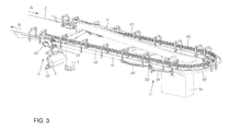
- FIG. 3 is a perspective illustration of the station according to FIG. 2 , the second device for adjusting and locking the safety bar of the chairs being located in a second operating position;
- FIG. 1A shows a detail of FIG. 1 , in an illustration which is on an enlarged scale in relation to FIG. 1 ;
- FIG. 1B shows the detail from FIG. 1A , as seen from the other side;
- FIG. 1C shows a further detail of FIG. 1 , in an illustration which is on an enlarged scale in relation to FIG. 1 ;
- FIG. 2A shows a detail from FIG. 2 , in an illustration which is on an enlarged scale in relation to FIG. 2 ;
- FIG. 2B shows the detail from FIG. 2A , as seen from the other side;
- FIG. 3A shows a detail of FIG. 3 , in an illustration which is on an enlarged scale in relation to FIG. 3 ;
- FIG. 3B shows the detail from FIG. 3A , as seen from the other side.
- FIG. 1 there is shown a terminal station of a cableway system with a load-bearing structure 10 which is borne by supports 1 and 1 a and on which a cable-reversing or cable-deflecting pulley 20 , also referred to as a head wheel 20 , for a conveying cable 2 of the cableway system is mounted such that it can be rotated about a more or less vertical axis.
- the conveying cable 2 is driven via at least one of the deflecting pulleys 20 located in the cableway system.
- a multiplicity of chairs 3 are coupled to the conveying cable 2 along the path of the cableway system.
- the chairs 3 are each multi-person chairs accommodating two, or three, or four, or six, or even eight or more passengers.
- the movement direction of the conveying cable 2 is indicated by arrows A and B.
- These chairs are uncoupled from the conveying cable 2 , whereupon they are moved through this station, along a guide rail 40 , by means of control tires 4 .
- the control tires 4 are driven in that they are coupled to at least one supporting roller of the conveying cable 2 , in order to be carried along therewith.
- a first group of control tires 4 here serve as decelerating tires 41 , by means of which the speed of the chairs 3 is reduced from, for example, 6 m/sec to, for example. 0.3 m/sec.
- the chairs 3 are moved at a speed of approximately 0.3 m/sec through a disembarking and boarding region for the passengers.
- the passengers disembark from and board the chairs in the process.
- a third group of control tires 4 these serving as accelerating tires 43 , the chairs 3 are accelerated to the travel speed of the conveying cable 2 , for example, 6 m/sec, whereupon they are coupled to the conveying cable 2 at the exit from the station.
- the chairs 3 are configured with a safety bar 31 which, as soon as passengers have boarded the chairs 3 , is adjusted into its closed position and locked, and which serves to prevent the passengers from sliding off the chairs 3 .
- a first adjusting device 5 which is provided on the load-bearing structure 10 , serves for adjusting the safety bar 31 into its closed position, and for locking the same.
- the adjusting device 5 has a control rail 51 , which is oriented obliquely in relation to the movement direction of the chairs 3 and along which runs a cam roller or control roller 32 , which is located on the chair 3 . As a result, the control roller 32 is pivoted and the pivoting movement causes the safety bar 31 to be moved into its closed position and locked therein.
- a checking device here, a sensor 50 , for instance, in the form of a pivotable rod—is provided in the movement path of the cam roller or control roller 32 , and this sensor emits a control signal when the control roller 32 is located in that pivoted position in which the safety bar 31 is located in its closed position and has been locked. If, in contrast, the sensor 50 does not emit any signal, because the control roller 32 is not located in this pivoting position, and it is not ensured that the safety bar 31 is located in its closed position and has not been locked either, operation of the known cableway system is interrupted.
- the cableway station contains, downstream of the first device 5 for adjusting the safety bar 31 into the closed position, and for locking the same, a second such adjusting device 6 , which is likewise provided with a control rail 61 and, when active, causes the control roller 32 , if not located in that pivoting position in which the safety bar 31 has been moved into its closed position and locked, to be pivoted into that position.
- this second adjusting device 6 is also assigned a sensor 60 , e.g. in the form of a pivotable rod, which checks the pivoting position of the control roller 32 , and thus the closed position and the locking of the safety bar 31 . If the control roller 32 , even after passing the second adjusting device 6 , is not located in that pivoting position in which the safety bar 31 is located in its closed position and has been locked, the cableway system is brought to a standstill.
- the second adjusting device 6 for the safety bar 31 is located in its inactive position. In contrast, the second adjusting device 6 is located in its active position in FIG. 3 .
- the control rail 51 can be pivoted in a vertical plane, about a more or less horizontal axis, by means of an adjusting motor 52 .
- a telescopic rod 53 which can be adjusted in its longitudinal direction by means of the drive motor 52 and which is designed with a transverse guide bolt 54 at its end which is directed away from the drive motor 52 .
- the control rail 51 has fastened on it a triangular carrying plate 55 , which is designed with a guide slot 56 , through which the guide bolt 54 passes.
- control rail 51 Also located on the control rail 51 are a plurality of bars 57 , which serve as weights and by means of which the control rail 51 is pivoted into its respectively lowermost position determined by the telescopic rod 53 . If the safety bar 31 of the relevant chair 3 does not pass into its closed position on account of an obstruction on the chair 3 , e.g. on account of a passenger's rucksack, the control rail 51 is raised, counter to the action of the weighting bars 57 , by the control roller 32 , this being possible by the adjustability of the guide bolt 54 in the guide slot 56 .
- the sensor 50 is located at that end of the control rail 51 which is located in the movement direction of the chairs 3 .
- the adjusting device 5 is always located in its active position.
- the control rail 51 is pivoted, by means of the drive motor 52 , into its upper, inactive position.
- FIG. 1C shows three positions of the control roller 32 , which is located on the chair 3 .
- the control roller 32 is mounted on an angled adjusting lever 33 , which can be adjusted between a first, upper pivoting position and a second, lower pivoting position.
- the adjusting lever 33 has articulated on it a Bowden cable 34 , by means of which the safety bar 31 of the chair 3 can be adjusted and locked.
- the control roller 32 runs onto the locking rail 51 in the direction of the arrow C
- the adjusting lever 33 with the control roller 32 is pivoted in a clockwise direction, as a result of which the safety bar 31 is pivoted into its closed position.
- the control lever 33 with the control roller 32 passes into an over-dead-center position, as a result of which the safety bar 31 is locked in the closed position.
- the adjusting lever 33 with the control roller 32 assumes a central position, which is illustrated by dashed lines. Locking of the safety bar 31 can take place only as soon as the obstruction has been removed in order for the safety bar 31 to be adjusted.
- control roller 32 If the control roller 32 is located in that lower pivoting position in which the safety bar 31 has been locked, movement of the control roller actuates the sensor 50 , and therefore the sensor emits a control signal to the effect that operation of the cableway system is continued. In contrast, in any other pivoting positions of the control roller 32 , the sensor 50 does not emit any control signal, whereupon the second control rail 61 is pivoted into its active position and preferably the drive speed of the cableway system is reduced.
- the second adjusting device 6 for the safety bar 31 also has a control rail 61 , which extends in the movement direction of the chairs 3 and can be pivoted vertically, about a framework-mounted pin 68 , by means of a drive motor 62 . It is also the case with this adjusting device 6 that the control rail 61 is coupled to the drive motor 62 via a telescopic rod 63 and a transverse guide bolt 64 , which passes through, and is guided in, a guide slot 66 , which is provided in a carrying plate 65 fastened on the control rail 61 . Furthermore, this control rail 61 is also designed with weighting bars 67 .
- the control rail 61 is usually located in a first pivoting position, which is illustrated in FIGS. 2A and 2B . This is the inactive, upper position of this control rail 61 , in which the control rollers 32 of the chairs 3 do not run on the control rail. If, in contrast, the control rail 61 has been moved into a second, lower pivoting position, which is illustrated in FIGS. 3 , 3 A and 3 B, it is located in its active position, in which the control roller 32 , which is located on the relevant chair 3 , runs on the control rail, as a result of which it is pivoted and as a result of which the safety bar 31 of the relevant chair 3 , if not already located in the closed position, is moved into this closed position and locked.
- the pivoting movement of the control rail 61 is limited by an adjustable stop 69 .
- the sensor 60 e.g. in the form of a control rod, is located on the control rail 61 , and this sensor is actuated when the control roller 32 is located in that pivoting position in which the safety bar 31 has been locked, as a result of which a control signal is emitted to the effect that the safety bar 31 of the relevant chair 3 is located in its closed position and has been locked therein, in which case operation of the cableway system can be continued.
- This cableway system operates as follows:
- the second adjusting device 6 for the safety bar 31 is located here in its inactive position.
- the senor 50 which is assigned to the first adjusting device 5 for the safety bar 31 , is not actuated, and therefore does not emit any operating signal, as the relevant chair 3 travels past, since the control roller 32 is not located in that pivoting position in which the safety bar 31 is located in its closed position and has been locked, on the one hand the second adjusting device 6 for the safety bar 31 is activated by the control rail 61 being moved into the second pivoting position by means of the adjusting motor 62 , and on the other hand the speed of the conveying cable 2 , and thus the drive speed of the accelerating tires 43 , which are coupled to the conveying cable 2 in order to be carried along therewith, are reduced.
- the control rail 61 passes into the movement path of the control roller 32 , which is located on the relevant chair 3 , as a result of which the control roller is pivoted, wherein this pivoting action causes the safety bar 31 , if not already located in the closed position, to be moved into this position and also to be locked.
- the sensor 60 which is assigned to the second adjusting device 6 , checks the pivoting position of the control roller 32 . If the control roller 32 is located in that pivoting position in which the safety bar 31 has been locked, the second sensor 60 is actuated. This emits an operating signal, by means of which normal operation of the cableway system is resumed. If, in contrast, the sensor 60 does not emit any operating signal, since the control roller 32 is not located in the pivoting position necessary for the locking of the safety bar 31 , the cableway system is brought to a standstill.
- the second adjusting device 6 is located in the region of the conveying tires 42 , there is no need to reduce the drive speed of the cableway system upon response of the sensor 50 , which is assigned to the first adjusting device 5 . If, however, the chairs 3 are accelerated between the first adjusting device 5 and the second adjusting device 6 , there is a need, upon response of the sensor 50 , for the speed at which the relevant chair 3 is guided through the second adjusting device 6 to be reduced in relation to normal operating speed.
- the sensor 50 which is assigned to the first adjusting device 5 , does not emit any signal, for operation of the cableway system to be brought to a standstill and for the safety bar 31 of the relevant chair 3 to be moved into its closed position.
- the control roller 32 runs onto the second locking rail 61 , as a result of which the control roller 32 is pivoted into its over-dead-center position, and the safety bar 31 is thus locked.
Landscapes
- Engineering & Computer Science (AREA)
- Transportation (AREA)
- Mechanical Engineering (AREA)
- Chairs For Special Purposes, Such As Reclining Chairs (AREA)
- Train Traffic Observation, Control, And Security (AREA)
- Electric Propulsion And Braking For Vehicles (AREA)
- Seats For Vehicles (AREA)
- Elevator Control (AREA)
- Types And Forms Of Lifts (AREA)
- Refuge Islands, Traffic Blockers, Or Guard Fence (AREA)
Applications Claiming Priority (2)
| Application Number | Priority Date | Filing Date | Title |
|---|---|---|---|
| ATA1275/2010 | 2010-07-29 | ||
| AT12752010 | 2010-07-29 |
Publications (2)
| Publication Number | Publication Date |
|---|---|
| US20120024187A1 US20120024187A1 (en) | 2012-02-02 |
| US8635958B2 true US8635958B2 (en) | 2014-01-28 |
Family
ID=44764069
Family Applications (1)
| Application Number | Title | Priority Date | Filing Date |
|---|---|---|---|
| US13/161,021 Active 2031-11-24 US8635958B2 (en) | 2010-07-29 | 2011-06-15 | Cable railway system and method of operating the same |
Country Status (11)
| Country | Link |
|---|---|
| US (1) | US8635958B2 (zh) |
| EP (1) | EP2412596B1 (zh) |
| JP (1) | JP5504522B2 (zh) |
| KR (1) | KR101385861B1 (zh) |
| CN (1) | CN102343913B (zh) |
| AT (1) | AT12420U1 (zh) |
| AU (1) | AU2011203497B2 (zh) |
| CA (1) | CA2743213C (zh) |
| ES (1) | ES2398735T3 (zh) |
| NZ (1) | NZ592915A (zh) |
| RU (1) | RU2516858C2 (zh) |
Cited By (2)
| Publication number | Priority date | Publication date | Assignee | Title |
|---|---|---|---|---|
| US11332166B2 (en) * | 2017-06-12 | 2022-05-17 | Innova Patent Gmbh | Cableway with lock monitoring for a vehicle |
| US11518418B2 (en) * | 2017-10-19 | 2022-12-06 | Innova Patent Gmbh | Tyre conveyor for transport means |
Families Citing this family (15)
| Publication number | Priority date | Publication date | Assignee | Title |
|---|---|---|---|---|
| ITMI20071618A1 (it) * | 2007-08-03 | 2009-02-04 | Rolic Invest Sarl | Impianto di trasporto a fune e metodo di azionamento dello stesso |
| EP2899728B2 (en) | 2014-01-22 | 2019-11-13 | ABB Schweiz AG | A device comprising a high voltage apparatus including a fluid and equipment for detecting one or more physical properties of the fluid |
| AT515733B1 (de) * | 2014-04-10 | 2016-02-15 | Innova Patent Gmbh | Seilbahnanlage |
| CN106864466B (zh) * | 2014-07-30 | 2019-11-12 | 王君华 | 一种安全型索道车 |
| JP6499838B2 (ja) * | 2014-08-25 | 2019-04-10 | 独立行政法人自動車技術総合機構 | 索道の椅子式搬器のセーフティバー警告装置及び警告方法 |
| AU2015310839B2 (en) * | 2014-09-04 | 2019-05-02 | Agence Nationale Pour La Gestion Des Dechets Radioactifs | Funicular driven by a cable with two towing sections and method for controlling such a funicular |
| ITUB20150167A1 (it) * | 2015-03-05 | 2016-09-05 | Eurotech S P A | Impianto di risalita a fune, metodo per incrementare la sicurezza di un impianto di risalita a fune e sistema di sicurezza per un impianto di risalita a fune |
| FR3037304B1 (fr) | 2015-06-12 | 2018-07-27 | Poma | Dispositif d'accouplement d'un vehicule a un cable tracteur, vehicule equipe d'un tel dispositif, et installation de transport par cable tracteur comprenant un tel vehicule |
| FR3044627B1 (fr) * | 2015-12-04 | 2018-01-05 | Poma | Installation de transport aerien |
| JP7138330B2 (ja) * | 2018-04-03 | 2022-09-16 | 日本ケーブル株式会社 | 索道における電力供給装置 |
| JP7138331B2 (ja) * | 2018-04-17 | 2022-09-16 | 日本ケーブル株式会社 | 索道における電力供給装置 |
| JP7435973B2 (ja) | 2020-02-28 | 2024-02-21 | 日本ケーブル株式会社 | チェアリフト搬器のセフティーバーロック装置 |
| AT523970A1 (de) * | 2020-07-06 | 2022-01-15 | Innova Patent Gmbh | Türsteuerung für eine Seilbahn |
| AT523971A1 (de) * | 2020-07-06 | 2022-01-15 | Innova Patent Gmbh | Türsteuerung für ein Seilbahnfahrzeug |
| CN112553981B (zh) * | 2020-09-07 | 2022-04-15 | 同济大学 | 一种用于索轨结构中的长线型索力控制系统及方法 |
Citations (2)
| Publication number | Priority date | Publication date | Assignee | Title |
|---|---|---|---|---|
| US20040003751A1 (en) | 2002-07-04 | 2004-01-08 | Reinhard Albrich | Apparatus for monitoring the locking of the safety bar of a chair in a cableway system |
| EP1780091A2 (de) | 2005-10-28 | 2007-05-02 | Innova Patent GmbH | Seilbahn zur Personenbeförderung mit einer Sicherungseinrichtung |
Family Cites Families (10)
| Publication number | Priority date | Publication date | Assignee | Title |
|---|---|---|---|---|
| JPS6385463U (zh) * | 1986-11-21 | 1988-06-03 | ||
| JPH0780452B2 (ja) * | 1988-09-24 | 1995-08-30 | 日本ケーブル株式会社 | スキーリフトの風防開閉装置 |
| AT396095B (de) * | 1991-04-22 | 1993-05-25 | Doppelmayr & Sohn | Sessel fuer eine sesselbahn |
| JPH08244599A (ja) * | 1995-03-10 | 1996-09-24 | Kawaden Co Ltd | 索道における搬器のフード開閉方法及びその装置 |
| US6494145B2 (en) * | 2000-09-15 | 2002-12-17 | Joseph F. Kernan | Automatic crossbar on ski chair-lift for facilitating passenger dismount |
| US20020043829A1 (en) * | 2000-10-04 | 2002-04-18 | Garaventa Holding Ag | Method and arrangement to close a bubble top for a chairlift |
| FR2879547B1 (fr) * | 2004-12-17 | 2007-03-02 | Pomagalski Sa | Mecanisme de commande a verrouillage d'un capot pivotant pour telesiege |
| AT503615A3 (de) * | 2006-04-26 | 2010-06-15 | Innova Patent Gmbh | Seilbahnanlage mit an ein trag- und förderseil ankuppelbaren fahrbetriebsmitteln |
| AT504614B1 (de) * | 2006-12-04 | 2009-02-15 | Innova Patent Gmbh | Schliessbügel eines sessels eines sesselliftes |
| ITMI20070157U1 (it) * | 2007-04-20 | 2008-10-21 | Rolic Invest Sarl | Seggiovia |
-
2011
- 2011-03-17 ES ES11450038T patent/ES2398735T3/es active Active
- 2011-03-17 EP EP11450038A patent/EP2412596B1/de active Active
- 2011-05-18 NZ NZ592915A patent/NZ592915A/en unknown
- 2011-05-25 KR KR1020110049663A patent/KR101385861B1/ko active IP Right Grant
- 2011-06-02 RU RU2011122502/11A patent/RU2516858C2/ru active
- 2011-06-14 CA CA2743213A patent/CA2743213C/en active Active
- 2011-06-15 JP JP2011133095A patent/JP5504522B2/ja not_active Expired - Fee Related
- 2011-06-15 US US13/161,021 patent/US8635958B2/en active Active
- 2011-06-20 CN CN201110165720.XA patent/CN102343913B/zh active Active
- 2011-07-11 AU AU2011203497A patent/AU2011203497B2/en not_active Ceased
- 2011-09-02 AT AT0807911U patent/AT12420U1/de not_active IP Right Cessation
Patent Citations (3)
| Publication number | Priority date | Publication date | Assignee | Title |
|---|---|---|---|---|
| US20040003751A1 (en) | 2002-07-04 | 2004-01-08 | Reinhard Albrich | Apparatus for monitoring the locking of the safety bar of a chair in a cableway system |
| EP1780091A2 (de) | 2005-10-28 | 2007-05-02 | Innova Patent GmbH | Seilbahn zur Personenbeförderung mit einer Sicherungseinrichtung |
| US7690313B2 (en) * | 2005-10-28 | 2010-04-06 | Innova Patent Gmbh | Cableway system with a safety device |
Cited By (2)
| Publication number | Priority date | Publication date | Assignee | Title |
|---|---|---|---|---|
| US11332166B2 (en) * | 2017-06-12 | 2022-05-17 | Innova Patent Gmbh | Cableway with lock monitoring for a vehicle |
| US11518418B2 (en) * | 2017-10-19 | 2022-12-06 | Innova Patent Gmbh | Tyre conveyor for transport means |
Also Published As
| Publication number | Publication date |
|---|---|
| AT12420U1 (de) | 2012-05-15 |
| US20120024187A1 (en) | 2012-02-02 |
| AU2011203497A1 (en) | 2012-02-16 |
| CN102343913A (zh) | 2012-02-08 |
| JP5504522B2 (ja) | 2014-05-28 |
| CA2743213C (en) | 2015-01-06 |
| EP2412596B1 (de) | 2012-12-12 |
| ES2398735T3 (es) | 2013-03-21 |
| NZ592915A (en) | 2012-06-29 |
| RU2516858C2 (ru) | 2014-05-20 |
| CN102343913B (zh) | 2015-05-06 |
| JP2012030781A (ja) | 2012-02-16 |
| EP2412596A1 (de) | 2012-02-01 |
| CA2743213A1 (en) | 2012-01-29 |
| AU2011203497B2 (en) | 2014-04-17 |
| KR20120012379A (ko) | 2012-02-09 |
| RU2011122502A (ru) | 2012-12-10 |
| KR101385861B1 (ko) | 2014-04-29 |
Similar Documents
| Publication | Publication Date | Title |
|---|---|---|
| US8635958B2 (en) | Cable railway system and method of operating the same | |
| CA2743623C (en) | Cable railway system | |
| US20070251407A1 (en) | Cableway system having transport devices that can be coupled to a conveying cable | |
| US7685947B2 (en) | Cable railway system | |
| US7690313B2 (en) | Cableway system with a safety device | |
| US20090151594A1 (en) | Cableway System with a Carrying and Conveying Cable | |
| US7490556B2 (en) | Cableway installation with rotatable cableway transport devices | |
| US20020007758A1 (en) | Installation for conveying persons | |
| US8418625B2 (en) | System for conveying persons and method for operating the system | |
| AU2013206586B2 (en) | Station for a cable railway system | |
| AU2014210672B2 (en) | Cableway system for transporting persons | |
| US20040011240A1 (en) | Aerial cableway system with at least one load-bearing and conveying cable moving between a valley station and a mountain station | |
| AU2021226837A1 (en) | Cableway having car stabilization | |
| NZ547270A (en) | Cableway installation with rotatable cableway transport devices | |
| US6526894B2 (en) | Traveling-gear mechanism for a transport assembly of a cableway system | |
| CA2588873A1 (en) | Cableway system having at least one conveying cable | |
| NZ612058B (en) | Station for a cable railway system |
Legal Events
| Date | Code | Title | Description |
|---|---|---|---|
| AS | Assignment |
Owner name: INNOVA PATENT GMBH, AUSTRIA Free format text: ASSIGNMENT OF ASSIGNORS INTEREST;ASSIGNOR:BECK, MARKUS;REEL/FRAME:029855/0731 Effective date: 20110519 |
|
| STCF | Information on status: patent grant |
Free format text: PATENTED CASE |
|
| FEPP | Fee payment procedure |
Free format text: PAYOR NUMBER ASSIGNED (ORIGINAL EVENT CODE: ASPN); ENTITY STATUS OF PATENT OWNER: LARGE ENTITY |
|
| FPAY | Fee payment |
Year of fee payment: 4 |
|
| MAFP | Maintenance fee payment |
Free format text: PAYMENT OF MAINTENANCE FEE, 8TH YEAR, LARGE ENTITY (ORIGINAL EVENT CODE: M1552); ENTITY STATUS OF PATENT OWNER: LARGE ENTITY Year of fee payment: 8 |