US8622271B2 - Fastener driving tool - Google Patents
Fastener driving tool Download PDFInfo
- Publication number
- US8622271B2 US8622271B2 US12/495,390 US49539009A US8622271B2 US 8622271 B2 US8622271 B2 US 8622271B2 US 49539009 A US49539009 A US 49539009A US 8622271 B2 US8622271 B2 US 8622271B2
- Authority
- US
- United States
- Prior art keywords
- plunger
- motor
- turned
- switch
- dead center
- Prior art date
- Legal status (The legal status is an assumption and is not a legal conclusion. Google has not performed a legal analysis and makes no representation as to the accuracy of the status listed.)
- Active, expires
Links
Images


Classifications
-
- B—PERFORMING OPERATIONS; TRANSPORTING
- B25—HAND TOOLS; PORTABLE POWER-DRIVEN TOOLS; MANIPULATORS
- B25C—HAND-HELD NAILING OR STAPLING TOOLS; MANUALLY OPERATED PORTABLE STAPLING TOOLS
- B25C1/00—Hand-held nailing tools; Nail feeding devices
- B25C1/06—Hand-held nailing tools; Nail feeding devices operated by electric power
-
- B—PERFORMING OPERATIONS; TRANSPORTING
- B25—HAND TOOLS; PORTABLE POWER-DRIVEN TOOLS; MANIPULATORS
- B25C—HAND-HELD NAILING OR STAPLING TOOLS; MANUALLY OPERATED PORTABLE STAPLING TOOLS
- B25C1/00—Hand-held nailing tools; Nail feeding devices
- B25C1/008—Safety devices
Definitions
- the present invention relates to a fastener driving tool, and more particularly, to an electrical fastener driving tool.
- a spring-driven nail gun that retracts a plunger against a resilient force of a spring and then releases the plunger for impacting a nail to a workpiece have been wellknown as an electric power tool.
- U.S. Pat. No. 3,589,588 discloses an electric power tool having a plunger which is retracted by a mechanism including a motor and decelerating gears in the tool, which reduces power required to retract the plunger.
- the tool includes a detecting switch that detects a release operation of the plunger. When the release operation is detected, the tool stops feed to the motor.
- An object of the invention is to provide a fastener driving tool which ceases an impacting operation in case a detecting switch is breakdown.
- the present invention features a fastener driving tool having a housing, a nose portion, a magazine, a motor, a plunger, a drive mechanism, a trigger switch, a detection switch, an energizing switch, a failure detection circuit.
- the magazine is configured to store and supply a fastener to the nose portion.
- the motor is provided in the housing.
- the a plunger is provided in the housing to move between a top dead center and a bottom dead center.
- the plunger has a blade for impacting the fastener.
- the drive mechanism is configured to drive the plunger with power from the motor.
- the trigger switch is configured to drive the drive mechanism, and operated by a user.
- the detection switch is configured to be switched according to an arrangement of the drive mechanism.
- the energizing switch is configured to control power feed of the motor.
- the energizing switch is switched by the trigger switch and the detection switch.
- the failure detection circuit is configured to turn off the energizing switch, based on a condition of the detection switch prior to impacting the fastener.
- FIG. 1 is a partial section showing an electric nail gun according to an embodiment of the present invention, in which a plunger is at a bottom dead center;
- FIG. 2A is a perspective view showing a spring compresssion release mechanism
- FIG. 2B is a partial exploded view showing the spring compression release mechanism of FIG. 2A ;
- FIG. 2C is an exploded view showing the spring compression release mechanism of FIG. 2A ;
- FIGS. 3A-3D are perspective views showing the the spring compression release mechanism with a drum being removed
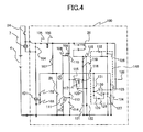
- FIG. 4 is a circuit diagram showing a controller according to the present invention.
- FIG. 5 is a timing chart of the controller during a normal operation.
- FIG. 6 is a timing chart of the controller when a stop switch is breakdown.
- FIG. 1 shows an electrically-operated type nail gun 1 that impacts a nail as a fastener into a workpiece such as a wood and a gypsum plaster board.
- the nail gun 1 mainly includes a housing 2 , a handle 3 , a battery 4 , a nose portion 5 , a magazine 6 , a trigger 10 , and a controller 100 .
- a direction in which a plunger 8 (described later) moves in the housing 2 to strike the nail will be described as a lateral direction.
- the housing 2 includes the plunger 8 , a spring 9 , a motor 7 , a decelerating mechanism 11 , a gear 14 , a guide plate 18 , a drum 13 , a wire 16 , and a stop switch 25 .
- the plunger 8 is arranged so as to move between a top dead center and a bottom dead center in the housing 2 .
- the plunger 8 has a blade 8 a .
- the blade 8 a has a tip end extending into a passage formed in the nose portion 5 .
- a disk-shaped plunger plate 8 b is arranged on the top dead center side of the plunger 8 .
- the center of the plunger plate 8 b is connected to the tip end of the blade 8 a on the top dead center side.
- the spring 9 is arranged between the plunger plate 8 b and a left end of the housing 2 shown in FIG. 1 .
- the motor 7 has a rotation shaft (not shown), and is rotated with electric power from the battery 4 to provide a torque to the decelerating mechanism 11 .
- the decelerating mechanism 11 has the motor 7 , a pulley (not shown) connected to the rotation shaft, gears, and a belt to generate a torque to an output shaft 19 described later (See FIGS. 2A to 2C ).
- the decelerating mechanism 11 amplifies a torque of the motor 7 , so the motor 7 used in the decelerating mechanism 11 can become compact.
- the drum 13 is rotated with the torque generated by the motor 7 and supplied through the decelerating mechanism 11 , interlocked with the operation of a compression release mechanism (a clutch mechanism) described later.
- the wire 16 is made with a plurality of metal rods wound and has some flexibility and strength.
- the wire 16 has a surface coated with a resin in order to avoid wearing due to contact with the drum 13 .
- the handle 3 extends from the housing 2 and is provided with the trigger 10 to control the operation of the motor 7 .
- a trigger switch 24 is provided in the handle 3 to be operated interlocking with the trigger 10 .
- the controller 100 is provided in the housing 2 .
- the battery 4 is detachably attached to an end of the housing 2 .
- the controller 100 feeds electric power from the battery 4 to the motor 7 by wiring (not shown) provided in the handle 3 .
- the magazine 6 is placed across the nose portion 5 and the top portion of the housing 2 .
- the magazine 6 accommodates a bunch of a plurality of nails (not shown) to supply the nail to the passage in the nose portion 5 .
- the length of the passage in the nose portion 5 is longer than the length of the nail, and provides an approach section to accelerate the nail until the nail becomes contact with the workpiece.
- the structure of the clutch mechanism as the compression release mechanism for the spring 9 will be described, referring to FIGS. 2A to 2C .
- the compression release mechanism for the spring 9 includes the decelerating mechanism 11 , the output shaft 19 of the decelerating mechanism 11 , the gear 14 , the guide plate 18 , a pin support plate 21 , a drum hook 22 , the drum 13 , a power transmission pin 17 , and the wire 16 .
- the gear 14 has a disk shape and has a fitting hole 14 b at the center.
- the fitting hole 14 b had a width across flat.
- a plurality of through holes 14 c are formed around the fitting hole 14 b .
- An extending portion 14 a is provided around the circumferential edge of an upper surface of the gear 14 .
- the output shaft 19 has a width across flat portion (not shown) which is cut in the shape of a width across flat. The width across flat portion of the output shaft 19 is inserted and fitted in the fitting hole 14 b of the gear 14 , so that the gear 14 is fixed to the output shaft 19 .
- the through holes 14 c are formed in the gear 14 for weight and inertia reduction of the gear 14 .
- the extending portion 14 a is formed in order to turn on and off the stop switch 25 by the engagement or disengagement with the stop switch 25 described later.
- the guide plate 18 is formed with a guide groove 18 a , a guide projection 18 b , a projection portion 18 d , and a through hole (not shown).
- the through hole is formed at a center of the guide plate 18 .
- the output shaft 19 are inserted through the through hole.
- the guide groove 18 a is formed adjacent to the through hole.
- the guide projection 18 b is formed around the through hole so as to have a portion which has a longer length from the through hole to the guide groove 18 a .
- the guide projection 18 b has a convex shape having a length of 5-15 mm in a radial direction from the center of the through hole.
- the projection portion 18 d has a rectangular shape and is formed at the outer periphery of guide plate 18 .
- a key 20 fixed to the output shaft 19 is provided on the upper surface of the guide projection 18 b .
- the key 20 has a outer shape having a width across flat in a horizontal cross section.
- the key 20 is fitted in a through hole 21 b of the pin support plate 21 described later.
- the stop switch 25 has a open/close portion 25 a having a rectangular shape.
- the stop switch 25 is turned on and off by opening and closing the open/close portion 25 a , respectively.
- the stop switch 25 is fixed to the guide plate 18 in order to be placed between the outer upper surface of the gear 14 and the lower surface of the projection portion 18 b of the guide plate 18 .
- the length of the stop switch 25 in the direction of the output shaft 19 is substantially equal to the height of extending portion 14 a of the gear 14 .
- the open/close portion 25 a is attached to the position in order that the engagement and disengagement with the extending portion 25 a is switched according to the rotation of the gear 14 .
- the pin support plate 21 has a through hole 21 b which is formed by forming out the width across flat hole in the body portion. An extending portion having a pin support slide portion 21 a extends from the body portion. When the key 20 is inserted in and engaged with the through hole 21 b , the pin support plate 21 is fixed to the output shaft 19 .
- a power transmission pin 17 includes a guide groove contact portion 17 a and a pin contact portion 17 b .
- the guide groove contact portion 17 a is able to be engaged in the guide groove 18 a . Accordingly, the moving direction and the moving distance of the power transmission pin 17 is controlled by the shape of the guide groove 18 a .
- the pin contact portion 17 b has the same height as that of a hook portion 22 a of a drum hook 22 , when being assembled with the compression release mechanism.
- the right side surface of the pin contact portion 17 b of the power transmission pin 17 is slid ably supported by the pin support slide portion 21 a.
- the above structure enables the pin support plate 21 and the power transmission pin 17 to rotate together in synchronization with the rotation of the output shaft 19 .
- the drum hook 22 includes a cylindrical main portion 22 c , a bearing 22 b , and a hook portion 22 a extending from the side surface of the main portion 22 c.
- the bearing 22 b is positioned so as to contact with the inner surface of the main portion 22 c ,.
- the output shaft 19 is inserted in he drum hook 22 through the bearing 22 b , so that the output shaft 19 and the drum hook 22 are not always rotated in synchronization with each other.
- the hook portion 22 a extends from the main portion 22 c in a direction perpendicular to the output shaft 19 and is able to contact with the pin contact portion 17 b of the power transmission pin 17 . Accordingly, the power transmission pin 17 always rotates in synchronization with the pin support plate 21 .
- the drum hook 22 rotates in synchronization with the pin support plate 21 and the power transmission pin 17 , only when the pin contact portion 17 b of the power transmission pin 17 becomes contact with the hook portion 22 a.
- the drum 13 has a disk shape.
- the drum 13 has a through hole 13 c at the center thereof, and the main portion 22 c of the drum hook 22 is pressed into the through hole 13 c ,. Accordingly, the drum 13 and the drum hook 22 rotate in synchronization with each other.
- a damper collision portion 13 a projects from the drum 13 in the axial direction of the output shaft 19 .
- the wire 16 is able to be wound around the lateral surface of the drum 13 and connects the drum 13 to the plunger 98 (see FIG. 1 ).
- the wire 16 is wound or rewound around the lateral surface of the drum 13 to move the plunger 8 .
- the operation of the spring compression release mechanism will be described, referring to FIGS. 3A to 3D .
- the plunger 8 is positioned at the bottom dead center at an initial stage of the impacting operation by nail gun 1 .
- electric power is supplied from the battery 4 to the motor 7 by the trigger switch 24 and the controller 100 to rotate the motor 7 .
- the torque generated by the motor 7 is transferred to the pin support plate 21 and the power transmission pin 17 through the decelerating mechanism 11 and the output shaft 19 .
- FIG. 3A shows the initial condition of the spring compression release mechanism.
- the pin contact portion 17 b is contact with the hook portion 22 a , the power transmission pin 17 and the drum hook 22 are engaged with each other to move together. Therefore, the pin support plate 21 is rotated, and the drum hook 22 and the drum 13 are rotated, simultaneously.
- the open/close portion 25 a of the stop switch 25 is positioned at a 90° angle in a clockwise direction with respect to the contact surface between the pin contact portion 17 b and the hook portion 22 a which are positioned at the initial condition.
- the extending portion 14 a of the gear 14 is positioned across the angular range from the above contact surface to 270° angle in a counterclockwise direction.
- the open/close portion 25 a of the stop switch 25 is engaged with the extending portion 14 a of the gear 14 to be closed.
- the stop switch 25 turns on immediately after the trigger switch 24 is turned on.
- FIG. 3B shows the pin support plate 21 which has been rotated by 180° angle from the condition shown in FIG. 3A in the counterclockwise direction.
- the drum 13 is rotated by 180° in synchronization with the rotation of the pin support plate 21 to entangle one end of the wire 16 to a drum concave portion 13 b .
- the plunger 8 connected to the other end of the wire 16 is pulled to move toward the top dead center.
- the plunger plate 8 b attached to the end of the plunger 8 compresses the spring 9 .
- the stop switch 25 is maintained turned on.
- the end of the power transmission pin 17 becomes contact with the guide projection 18 b of the guide groove 18 a .
- the guide projection 18 b has the convex shape having a length of 5-15 mm from the rotation axis in the radial direction.
- the power transmission pin 17 moves outward along the pin support slide portion 21 a in the radial direction and along the shape of the guide projection 18 b .
- the open/close portion 25 a of the stop switch 25 maintains the engagement with the extending portion 14 a and is turned on.
- the open/close portion 25 b is turned on by the extending portion 14 a of the gear 14 in the initial condition.
- the stop switch 25 is turned on immediately after the trigger switch 25 is turned on.
- the drum 13 is rotated by 270° angle with the stop switch 25 , maintaining the on condition, the power transmission pin 17 is disengaged from the hook portion 22 a , and the drum 13 starts reverse-rotation. These operation causes the impacting operation.
- the stop switch 25 is disengaged from the extending portion 14 a of the gear 14 , and the stop switch 25 is turned off. Due to the inertia of rotation, the gear 14 is further rotated, is back to nearly 0° angle, and returns to the condition shown in FIG. 3A .
- the configuration of the controller 100 will be described referring to the block diagram shown in FIG. 4 .
- the controller 100 includes a field-effect transistor (FET) 101 as an energizing switch, a PNP transistor 110 , an NPN transistor 111 , a PNP transistor 115 , a capacitor 114 , a capacitor 121 , the stop switch 25 , and a failure detection circuit 140 .
- FET field-effect transistor
- an N-channel FET is used as the FET 101 .
- the FET 101 is electrically connected to the battery 4 , the trigger switch 24 , and the motor 7 in series.
- a resistor 103 is connected between the gate and the source of the FET 101 .
- a resistor 102 is connected to the gate of the FET 101 .
- the resistor 102 is connected to a ground through a remaining nail amount detection switch 26 .
- the remaining nail amount detection switch 26 detects the remaining amount of the nails in the magazine 6 .
- the remaining nail amount detection switch 26 is turned off if the remaining amount of nails is more than a predetermined amount.
- the remaining nail amount detection switch 26 is turned on if the remaining amount of nails is less than or equal to the predetermined amount.
- a diode 104 is connected between the two terminals of the motor 7 to prevent generation of a fly back voltage.
- a smoothing circuit includes a resistor 105 and a capacitor 106 , and is connected to the higher potential terminal of the motor 7 .
- the output terminal of the smoothing circuit is connected to the gate of the FET 101 through resistors 107 and 102 .
- the output terminal of the smoothing circuit is connected to the emitter of the PNP transistor 110 .
- a resistor 109 is connected between the base and the emitter of the PNP transistor 110 .
- the base of the PNP transistor 110 is connected to the collector of the NPN transistor 111 through a resistor 108 .
- the collector of the PNP transistor 110 is connected to the base of the NPN transistor 111 through a resistor 113 .
- a resistor 112 is connected to the capacitor 114 in parallel.
- the parallel-connected resistor 112 and capacitor 114 is connected between the base and the emitter of the NPN transistor 111 .
- the emitter of the NPN transistor 111 is further connected to the negative terminal of the battery 4 .
- the collector of the NPN transistor 111 is connected to the gate of the FET 101 through the resistor 102 .
- the node between the resistor 108 and the collector of the NPN transistor 111 is designated as a node A hereinafter.
- the output terminal of the smoothing circuit is connected to one end of the stop switch 25 .
- the other end of the stop switch 25 is the negative terminal of the battery 4 through a resistor 122 .
- a diode 118 for backflow prevention, a resistor 119 , and the capacitor 121 are connected in series in this order between the other end of the stop switch 25 and the negative terminal of the battery 4 .
- the output terminal of the resistor 119 is further connected to the emitter of the PNP transistor 115 .
- a resistor 116 is connected between the base and the emitter of the PNP transistor 115 .
- the base of the PNP transistor 115 is further connected to the other end of the stop switch 25 through a resistor 117 and a diode 120 .
- the collector of the PNP transistor 115 is connected to the collector of the PNP transistor 110 .
- the failure detection circuit 140 includes an operational amplifier (Op-Amp) 130 , resistors 123 , 126 , 127 , and 128 , diodes 125 , 129 , and 131 , and a capacitor 124 .
- the resistors 126 and 127 are connected in series between the output terminal of the smoothing circuit and the negative terminal of the battery 4 .
- the voltage obtained by dividing the smoothed voltage Vs by the resistors 126 and 127 is applied to the non-inverting input terminal of the Op-amp 130 .
- the non-inverting input terminal of the Op-amp 130 is connected to the other end of the stop switch 25 through a diode 132 .
- the non-inverting input terminal of the Op-amp 130 is connected to the output terminal thereof through the resistor 128 and the diode 129 .
- the resistor 128 and the diode 129 constitute a Schmitt trigger circuit performing a positive feedback.
- the inverting input terminal is connected to the gate resistor 102 of the FET 101 through the resistor 123 , and connected to the ground through the capacitor 124 , so that the capacitor 124 is charged through the resistor 123 .
- the inverting input terminal is connected to the output terminal of the smoothing circuit through the diode 125 .
- the output terminal of the Op-amp 130 is connected to the gate resistor 102 through the diode 131 . It is noted that the smoothed voltage Vs is applied to the Op-amp 130 as a power supply to the Op-amp 130 .
- FIG. 5 shows time charts of the controller 100 under a normal operation.
- the smoothed voltage Vs is applied from the smoothing circuit to the gate of the FET 101 to turn on the FET 101 , so that a current flow starts flowing to the motor 7 .
- the motor 7 then starts rotating, and the pin support plate 21 and the drum 13 also start rotating.
- the resistor 103 has a sufficient larger resistance than the resistances of the resistors 108 and 109 (for example, approximate 10 times) in order to prevent the PNP transistor 110 from turning on immediately after the trigger switch 24 is turned on.
- the stop switch 25 When the stop switch 25 is turned on immediately after the trigger switch 24 is turned on, the charging the capacitor 121 starts through the diode 118 and the resistor 119 .
- the stop switch 25 is maintained on while the rotation angle of the drum 13 stays within the range from 0° to 270° angles.
- the emitter potential of the PNP transistor 115 When the stop switch 25 is maintained on, the emitter potential of the PNP transistor 115 is lower than the cathode potential of the diode 120 . Under this condition, the potential difference to turn on the PNP transistor 115 does not appear between the base and the emitter of the PNP transistor 115 . Accordingly, the PNP transistor 115 is maintained off.
- the smoothed voltage Vs is divided by the resistors 126 and 127 .
- the input voltage to the non-inverting input terminal is set to be approximately a half of the smoothed voltage, when the smoothed voltage is divided by the resistors 126 and 127 to the input voltage. This input voltage is obtained if the resistances of the resistors 126 and 127 are set identical.
- the smoothed voltage Vs is applied to the non-inverting input terminal of the Op-amp 130 through the stop switch 25 and the diode 132 .
- the smoothed voltage Vs is applied to the capacitor 124 through the resistors 107 and 123 to charge the capacitor 124 .
- the voltage across the capacitor 124 is applied to the inverting input terminal of the Op-amp 130 .
- the input voltage to the inverting input terminal is always lower than the smoothed voltage Vs, though the capacitor 124 is charged.
- a High output appears at the output terminal of the Op-amp 130 . This High output is interrupted by the diode 131 .
- the input voltage at the non-inverting input terminal of the Op-amp 130 becomes the voltage appearing across the resistor 127 which is obtained by dividing the smoothed voltage Vs by the resistors 126 and 127 .
- the output of the Op-amp 130 becomes Low, because the input voltage at the non-inverting input terminal becomes lower than the input voltage at the inverting input terminal.
- the current flow flows through the resistor 128 by the diode 129 , and the input voltage at the non-inverting input terminal further drops.
- the Low output of the Op-amp 130 causes the potential of the node A to become O volt, which turns off the FET 101 and the current flow ceases flowing to the motor 7 .
- the output voltage of the Op-amp 130 is changed to High. However, the High output of the Op-amp 130 is interrupted by the diode 131 . Further, the potential at the node A is maintained 0 volt, because the transistors 110 and 111 are maintained to be turned on until the trigger switch 24 is turned off.
- the base of the PNP transistor 115 is connected to the ground through the resistor 117 , the diode 120 , and the resistor 122 , and the emitter of the PNP transistor 115 is connected to the charged capacitor 121 . Then, a potential difference occurs between the base and the emitter of the PNP transistor 115 . Accordingly, the PNP transistor 115 is turned on, and the electric charge in the capacitor 121 is flown to the capacitor 114 through the resistor 1 13 .
- the potential at the base of the NPN transistor 111 rises to turn on the NPN transistor 111 .
- the NPN transistor 111 is turned on, the potential at the node A becomes the ground, and the potential at the gate of the FET 101 becomes the ground. Therefore, the FET 101 is turned off and the current flow to the motor 7 is ceased.
- the NPN transistor 111 When the NPN transistor 111 is turned on, the base of the PNP transistor 110 is also connected to the ground level through the resistor 108 , and the transistor 110 is turned on. As long as the trigger switch 24 is maintained closed, the smoothed voltage is applied to the base of the NPN transistor 111 , which maintains the NPN transistor 111 turned on. Accordingly, once the NPN transistor 111 is turned on, the NPN transistor 111 is maintained on, i.e., the FET 101 is maintained off, even if all electric charge stored in the capacitor 121 is discharged. It is preferable that the capacitance of the capacitor 114 is set to be larger than the capacitance of the capacitor 121 .
- the PNP transistor 110 When the trigger switch 24 is turned off, the PNP transistor 110 is turned off, and the off condition of the FET 101 can be released. And then, if the trigger switch 24 is again turned on, the FET 101 is turned on to energize the motor 7 .
- the above operation of the controller 100 enables the nail gun 1 to impact the nail.
- the single impact of the nail has been implemented, if the FET 101 is turned off after finishing the single operation to impact the nail.
- the controller 100 prevents impacting the nail as follows.
- the output voltage from the Op-amp 130 is interrupted by the diodes 129 and 131 .
- the output of the Op-amp 130 becomes Low output.
- the resistance of the positive feedback resistor 128 is set to be one third of the smoothed voltage Vs which is obtained by dividing the smoothed voltage Vs by the resistance of the resistor 126 and the parallel-connected combined resistance of the resistors 127 and 128 .
- the Low output of the Op-amp 130 causes the voltage of the node A to be maintained 0 volt by the diode 131 , so that the gate voltage of the FET 101 drops to 0 volt by the resistor 102 , the FET 101 is turned off to interrupt the power supply to the motor 7 .
- the time period from t 0 to t 11 is set longer than the time period from t 0 to t 1 because of the combination of the proper resistance of the resistor 123 and the proper capacitance of the capacitor 124 .
- the time period from t 0 to t 11 is set a sufficient short time such as 30 ms in order to cease the impact operation.
- the stop switch 25 is turned on immediately after the trigger switch 24 is turned on, and turned off after the impacting action is over.
- the output of the Op-amp 130 becomes a Low
- the gate terminal voltage of the FET 101 becomes 0 volt to turn off the FET 101 .
- the failure detection circuit 140 monitors whether the stop switch 25 is switched or not prior to impacting the nail. If the stop switch 25 is not switched, the controller 100 causes the FET to turn off for stopping feed to the motor 7 . Accordingly, the impacting action is prevented when the stop switch 25 is breakdown.
- the plunger 8 is positioned at the bottom dead center in the initial condition.
- an amount of time period from the operation of the trigger to the beginning of the impact action may change due to the repeated operations of the trigger switch.
- the impacting operation of the nail gun is prohibited without providing a specific mechanism prior to performing the impacting nail according to the operation of the trigger switch if the stop switch is breakdown.
- the nail gun which is easy to operate, reliable, and at low cost can be provided.
- a micro computer having the same functions can be used instead of the failure detection circuit 140 .
Landscapes
- Engineering & Computer Science (AREA)
- Mechanical Engineering (AREA)
- Portable Nailing Machines And Staplers (AREA)
Applications Claiming Priority (2)
| Application Number | Priority Date | Filing Date | Title |
|---|---|---|---|
| JP2008-171274 | 2008-06-30 | ||
| JP2008171274A JP5348608B2 (ja) | 2008-06-30 | 2008-06-30 | 電動式打込機 |
Publications (2)
| Publication Number | Publication Date |
|---|---|
| US20090321492A1 US20090321492A1 (en) | 2009-12-31 |
| US8622271B2 true US8622271B2 (en) | 2014-01-07 |
Family
ID=41152940
Family Applications (1)
| Application Number | Title | Priority Date | Filing Date |
|---|---|---|---|
| US12/495,390 Active 2029-10-13 US8622271B2 (en) | 2008-06-30 | 2009-06-30 | Fastener driving tool |
Country Status (4)
| Country | Link |
|---|---|
| US (1) | US8622271B2 (ja) |
| EP (1) | EP2140979B1 (ja) |
| JP (1) | JP5348608B2 (ja) |
| CN (1) | CN101618537B (ja) |
Cited By (6)
| Publication number | Priority date | Publication date | Assignee | Title |
|---|---|---|---|---|
| US20110114345A1 (en) * | 2009-11-17 | 2011-05-19 | Gerd Schlesak | Handheld power tool device |
| US20140263535A1 (en) * | 2013-03-12 | 2014-09-18 | Techtronic Power Tools Technology Limited | Direct current fastening device and related control methods |
| US20150314432A1 (en) * | 2012-11-05 | 2015-11-05 | Makita Corporation | Driving tool |
| US10286534B2 (en) | 2014-04-16 | 2019-05-14 | Makita Corporation | Driving tool |
| US10427284B2 (en) * | 2016-02-02 | 2019-10-01 | Makita Corporation | Fastener driving tool |
| US11065749B2 (en) | 2018-03-26 | 2021-07-20 | Tti (Macao Commercial Offshore) Limited | Powered fastener driver |
Families Citing this family (14)
| Publication number | Priority date | Publication date | Assignee | Title |
|---|---|---|---|---|
| DE102011089860A1 (de) * | 2011-12-23 | 2013-06-27 | Hilti Aktiengesellschaft | Eintreibvorrichtung |
| JP5800749B2 (ja) | 2012-04-09 | 2015-10-28 | 株式会社マキタ | 打込み工具 |
| JP5800748B2 (ja) | 2012-04-09 | 2015-10-28 | 株式会社マキタ | 打込み工具 |
| JP5758841B2 (ja) | 2012-05-08 | 2015-08-05 | 株式会社マキタ | 打ち込み工具 |
| US11229995B2 (en) | 2012-05-31 | 2022-01-25 | Black Decker Inc. | Fastening tool nail stop |
| US9827658B2 (en) | 2012-05-31 | 2017-11-28 | Black & Decker Inc. | Power tool having latched pusher assembly |
| WO2014156470A1 (ja) | 2013-03-29 | 2014-10-02 | 日立工機株式会社 | 打込機 |
| JP5991437B2 (ja) | 2013-07-31 | 2016-09-14 | 日立工機株式会社 | 打込機 |
| US10434634B2 (en) * | 2013-10-09 | 2019-10-08 | Black & Decker, Inc. | Nailer driver blade stop |
| JP6100680B2 (ja) | 2013-12-11 | 2017-03-22 | 株式会社マキタ | 打ち込み工具 |
| EP3970918A1 (en) * | 2015-04-24 | 2022-03-23 | Koki Holdings Co., Ltd. | Electric tool |
| CN112020410A (zh) * | 2018-04-26 | 2020-12-01 | 工机控股株式会社 | 打入机 |
| JP7115025B2 (ja) * | 2018-05-18 | 2022-08-09 | 工機ホールディングス株式会社 | 打込機 |
| TWI819002B (zh) * | 2019-06-11 | 2023-10-21 | 鑽全實業股份有限公司 | 電動釘槍及其開關檢測方法 |
Citations (35)
| Publication number | Priority date | Publication date | Assignee | Title |
|---|---|---|---|---|
| US3589588A (en) * | 1969-07-14 | 1971-06-29 | George O Vasku | Impact tool |
| US5495161A (en) * | 1994-01-05 | 1996-02-27 | Sencorp | Speed control for a universal AC/DC motor |
| US5511715A (en) * | 1993-02-03 | 1996-04-30 | Sencorp | Flywheel-driven fastener driving tool and drive unit |
| US5919203A (en) * | 1998-01-21 | 1999-07-06 | Royce H. Husted | Powered surgical tool |
| WO2002051591A1 (en) | 2000-12-22 | 2002-07-04 | Senco Products, Inc. | Control module for flywheel operated hand tool |
| US6598684B2 (en) * | 2000-11-17 | 2003-07-29 | Makita Corporation | Impact power tools |
| US20030149508A1 (en) * | 2002-02-07 | 2003-08-07 | Masahiro Watanabe | Power tools |
| US6604666B1 (en) * | 2001-08-20 | 2003-08-12 | Tricord Solutions, Inc. | Portable electrical motor driven nail gun |
| US20040026475A1 (en) * | 2002-08-09 | 2004-02-12 | Hitachi Koki Co., Ltd. | Combustion-powered nail gun |
| US6705503B1 (en) * | 2001-08-20 | 2004-03-16 | Tricord Solutions, Inc. | Electrical motor driven nail gun |
| US6783045B2 (en) * | 2002-08-09 | 2004-08-31 | Hitachi Koki Co., Ltd. | Combustion-powered nail gun |
| US6796475B2 (en) * | 2000-12-22 | 2004-09-28 | Senco Products, Inc. | Speed controller for flywheel operated hand tool |
| US20050217873A1 (en) * | 2004-04-02 | 2005-10-06 | Paul Gross | Solenoid positioning methodology |
| US20050218174A1 (en) * | 2004-04-02 | 2005-10-06 | Kenney James J | Activation arm configuration for a power tool |
| US6971567B1 (en) * | 2004-10-29 | 2005-12-06 | Black & Decker Inc. | Electronic control of a cordless fastening tool |
| US6983871B2 (en) * | 2002-08-09 | 2006-01-10 | Hitachi Koki Co., Ltd. | Combustion-powered nail gun |
| US7137541B2 (en) * | 2004-04-02 | 2006-11-21 | Black & Decker Inc. | Fastening tool with mode selector switch |
| US20070215664A1 (en) * | 2004-02-09 | 2007-09-20 | Moeller Larry M | Fan control for combustion-powered fastener-driving tool based on firing rate |
| US7285877B2 (en) * | 2004-04-02 | 2007-10-23 | Black & Decker Inc. | Electronic fastening tool |
| EP1867439A1 (en) | 2006-06-12 | 2007-12-19 | Makita Corporation | Driving power tool |
| US20080017689A1 (en) * | 2006-05-31 | 2008-01-24 | David Simonelli | Fastener driving device |
| US20080047999A1 (en) * | 2004-04-02 | 2008-02-28 | Alan Berry | Lock-out for activation arm mechanism in a power tool |
| US20080257934A1 (en) * | 2007-04-18 | 2008-10-23 | Hideyuki Tanimoto | Nailing machine |
| US7464846B2 (en) * | 2006-01-31 | 2008-12-16 | Ethicon Endo-Surgery, Inc. | Surgical instrument having a removable battery |
| US7467739B2 (en) * | 2004-09-29 | 2008-12-23 | Hitachi Koki Co., Ltd. | Combustion-powered, fastener-driving tool generating sparks in succession when triggered |
| US7469811B2 (en) * | 2006-09-14 | 2008-12-30 | Hitachi Koko Co., Ltd. | Electric driving machine |
| US7494036B2 (en) * | 2006-09-14 | 2009-02-24 | Hitachi Koki Co., Ltd. | Electric driving machine |
| US20090071998A1 (en) * | 2007-09-03 | 2009-03-19 | Hitachi Koki Co., Ltd. | Driving machine |
| US20090179062A1 (en) * | 2008-01-15 | 2009-07-16 | Hitachi Koki Co., Ltd. | Fastener driving tool |
| US7646157B2 (en) * | 2007-03-16 | 2010-01-12 | Black & Decker Inc. | Driving tool and method for controlling same |
| US7652442B2 (en) * | 2006-06-29 | 2010-01-26 | Matsushitu Electric Works, Ltd. | Electric tool switch mechanism |
| US7832610B2 (en) * | 2007-03-26 | 2010-11-16 | Hitachi Koki Co., Ltd. | Fastener driving tool having impact buffering mechanism |
| US8186553B2 (en) * | 2007-04-03 | 2012-05-29 | Hitachi Koki Co., Ltd. | Fastener driving tool |
| US8251271B2 (en) * | 2008-11-28 | 2012-08-28 | Hitachi Koki Co., Ltd. | Nailing machine |
| US8393512B2 (en) * | 2007-03-26 | 2013-03-12 | Hitachi Koki Co., Ltd. | Fastener driving tool |
-
2008
- 2008-06-30 JP JP2008171274A patent/JP5348608B2/ja active Active
-
2009
- 2009-06-30 US US12/495,390 patent/US8622271B2/en active Active
- 2009-06-30 EP EP09008574.7A patent/EP2140979B1/en active Active
- 2009-06-30 CN CN2009101396274A patent/CN101618537B/zh active Active
Patent Citations (39)
| Publication number | Priority date | Publication date | Assignee | Title |
|---|---|---|---|---|
| US3589588A (en) * | 1969-07-14 | 1971-06-29 | George O Vasku | Impact tool |
| US5511715A (en) * | 1993-02-03 | 1996-04-30 | Sencorp | Flywheel-driven fastener driving tool and drive unit |
| US5495161A (en) * | 1994-01-05 | 1996-02-27 | Sencorp | Speed control for a universal AC/DC motor |
| US5919203A (en) * | 1998-01-21 | 1999-07-06 | Royce H. Husted | Powered surgical tool |
| US6598684B2 (en) * | 2000-11-17 | 2003-07-29 | Makita Corporation | Impact power tools |
| WO2002051591A1 (en) | 2000-12-22 | 2002-07-04 | Senco Products, Inc. | Control module for flywheel operated hand tool |
| US20020185514A1 (en) * | 2000-12-22 | 2002-12-12 | Shane Adams | Control module for flywheel operated hand tool |
| JP2004536542A (ja) | 2000-12-22 | 2004-12-02 | センコ プロダクツ、インコーポレーテッド | フライホイール作動形手持ち式工具用制御モジュール |
| US6974061B2 (en) * | 2000-12-22 | 2005-12-13 | Senco Products, Inc. | Control module for flywheel operated hand tool |
| US6796475B2 (en) * | 2000-12-22 | 2004-09-28 | Senco Products, Inc. | Speed controller for flywheel operated hand tool |
| US6604666B1 (en) * | 2001-08-20 | 2003-08-12 | Tricord Solutions, Inc. | Portable electrical motor driven nail gun |
| US6705503B1 (en) * | 2001-08-20 | 2004-03-16 | Tricord Solutions, Inc. | Electrical motor driven nail gun |
| US20030149508A1 (en) * | 2002-02-07 | 2003-08-07 | Masahiro Watanabe | Power tools |
| US6983871B2 (en) * | 2002-08-09 | 2006-01-10 | Hitachi Koki Co., Ltd. | Combustion-powered nail gun |
| US6783045B2 (en) * | 2002-08-09 | 2004-08-31 | Hitachi Koki Co., Ltd. | Combustion-powered nail gun |
| US20040026475A1 (en) * | 2002-08-09 | 2004-02-12 | Hitachi Koki Co., Ltd. | Combustion-powered nail gun |
| US20060283909A1 (en) * | 2002-08-09 | 2006-12-21 | Hitachi Koki Co.,Ltd. | Combustion-powered nail gun |
| US20070215664A1 (en) * | 2004-02-09 | 2007-09-20 | Moeller Larry M | Fan control for combustion-powered fastener-driving tool based on firing rate |
| US20050217873A1 (en) * | 2004-04-02 | 2005-10-06 | Paul Gross | Solenoid positioning methodology |
| US20050218174A1 (en) * | 2004-04-02 | 2005-10-06 | Kenney James J | Activation arm configuration for a power tool |
| US7137541B2 (en) * | 2004-04-02 | 2006-11-21 | Black & Decker Inc. | Fastening tool with mode selector switch |
| US7285877B2 (en) * | 2004-04-02 | 2007-10-23 | Black & Decker Inc. | Electronic fastening tool |
| US20080047999A1 (en) * | 2004-04-02 | 2008-02-28 | Alan Berry | Lock-out for activation arm mechanism in a power tool |
| US7467739B2 (en) * | 2004-09-29 | 2008-12-23 | Hitachi Koki Co., Ltd. | Combustion-powered, fastener-driving tool generating sparks in succession when triggered |
| US6971567B1 (en) * | 2004-10-29 | 2005-12-06 | Black & Decker Inc. | Electronic control of a cordless fastening tool |
| US7464846B2 (en) * | 2006-01-31 | 2008-12-16 | Ethicon Endo-Surgery, Inc. | Surgical instrument having a removable battery |
| US20080017689A1 (en) * | 2006-05-31 | 2008-01-24 | David Simonelli | Fastener driving device |
| EP1867439A1 (en) | 2006-06-12 | 2007-12-19 | Makita Corporation | Driving power tool |
| US7652442B2 (en) * | 2006-06-29 | 2010-01-26 | Matsushitu Electric Works, Ltd. | Electric tool switch mechanism |
| US7469811B2 (en) * | 2006-09-14 | 2008-12-30 | Hitachi Koko Co., Ltd. | Electric driving machine |
| US7494036B2 (en) * | 2006-09-14 | 2009-02-24 | Hitachi Koki Co., Ltd. | Electric driving machine |
| US7646157B2 (en) * | 2007-03-16 | 2010-01-12 | Black & Decker Inc. | Driving tool and method for controlling same |
| US7832610B2 (en) * | 2007-03-26 | 2010-11-16 | Hitachi Koki Co., Ltd. | Fastener driving tool having impact buffering mechanism |
| US8393512B2 (en) * | 2007-03-26 | 2013-03-12 | Hitachi Koki Co., Ltd. | Fastener driving tool |
| US8186553B2 (en) * | 2007-04-03 | 2012-05-29 | Hitachi Koki Co., Ltd. | Fastener driving tool |
| US20080257934A1 (en) * | 2007-04-18 | 2008-10-23 | Hideyuki Tanimoto | Nailing machine |
| US20090071998A1 (en) * | 2007-09-03 | 2009-03-19 | Hitachi Koki Co., Ltd. | Driving machine |
| US20090179062A1 (en) * | 2008-01-15 | 2009-07-16 | Hitachi Koki Co., Ltd. | Fastener driving tool |
| US8251271B2 (en) * | 2008-11-28 | 2012-08-28 | Hitachi Koki Co., Ltd. | Nailing machine |
Non-Patent Citations (1)
| Title |
|---|
| Japan Patent Office office action for patent application JP2008-171274 (Nov. 29, 2012). |
Cited By (9)
| Publication number | Priority date | Publication date | Assignee | Title |
|---|---|---|---|---|
| US20110114345A1 (en) * | 2009-11-17 | 2011-05-19 | Gerd Schlesak | Handheld power tool device |
| US9144875B2 (en) * | 2009-11-17 | 2015-09-29 | Robert Bosch Gmbh | Handheld power tool device |
| US20150314432A1 (en) * | 2012-11-05 | 2015-11-05 | Makita Corporation | Driving tool |
| US10272553B2 (en) * | 2012-11-05 | 2019-04-30 | Makita Corporation | Driving tool |
| US20140263535A1 (en) * | 2013-03-12 | 2014-09-18 | Techtronic Power Tools Technology Limited | Direct current fastening device and related control methods |
| US10286534B2 (en) | 2014-04-16 | 2019-05-14 | Makita Corporation | Driving tool |
| US10427284B2 (en) * | 2016-02-02 | 2019-10-01 | Makita Corporation | Fastener driving tool |
| US11065749B2 (en) | 2018-03-26 | 2021-07-20 | Tti (Macao Commercial Offshore) Limited | Powered fastener driver |
| US11654538B2 (en) | 2018-03-26 | 2023-05-23 | Techtronic Power Tools Technology Limited | Powered fastener driver |
Also Published As
| Publication number | Publication date |
|---|---|
| CN101618537B (zh) | 2011-06-01 |
| EP2140979A1 (en) | 2010-01-06 |
| US20090321492A1 (en) | 2009-12-31 |
| JP5348608B2 (ja) | 2013-11-20 |
| JP2010005776A (ja) | 2010-01-14 |
| EP2140979B1 (en) | 2016-08-31 |
| CN101618537A (zh) | 2010-01-06 |
Similar Documents
| Publication | Publication Date | Title |
|---|---|---|
| US8622271B2 (en) | Fastener driving tool | |
| US8631986B2 (en) | Fastener driver with an operating switch | |
| JP4692932B2 (ja) | 電動式打込機 | |
| USRE43041E1 (en) | Control module for flywheel operated hand tool | |
| JP4556188B2 (ja) | 電動式打込機 | |
| JP5146736B2 (ja) | 留め具打込機 | |
| JP5146734B2 (ja) | 留め具打込機 | |
| EP1349710B1 (en) | Control module for flywheel operated hand tool | |
| US11097408B2 (en) | Driving tool | |
| JP5424009B2 (ja) | 留め具打込機 | |
| JP2008068356A (ja) | 電動式打込機 | |
| WO2005098885A2 (en) | Method for operating a power driver | |
| JP5288322B2 (ja) | 打込機 | |
| JP2008264970A (ja) | 打込機 | |
| JP5256972B2 (ja) | 電動式打込機 | |
| JP2010005714A (ja) | 電動式打込機 | |
| JP4882683B2 (ja) | 電動式打込機 | |
| TW200835581A (en) | Electric driving machine | |
| JP5146904B2 (ja) | 打込機 | |
| JP2008068359A (ja) | 留め具打込機 | |
| JP5382396B2 (ja) | 打込機 | |
| JP5257684B2 (ja) | 電動式打込機 | |
| AU2002231229A1 (en) | Control module for flywheel operated hand tool |
Legal Events
| Date | Code | Title | Description |
|---|---|---|---|
| AS | Assignment |
Owner name: HITACHI KOKI CO., LTD., JAPAN Free format text: ASSIGNMENT OF ASSIGNORS INTEREST;ASSIGNORS:SHIMA, YUKIHIRO;ODA, HIROYUKI;NAKANO, YOSHIHIRO;AND OTHERS;REEL/FRAME:022897/0633 Effective date: 20090629 |
|
| STCF | Information on status: patent grant |
Free format text: PATENTED CASE |
|
| FPAY | Fee payment |
Year of fee payment: 4 |
|
| AS | Assignment |
Owner name: KOKI HOLDINGS CO., LTD., JAPAN Free format text: CHANGE OF NAME;ASSIGNOR:HITACHI KOKI KABUSHIKI KAISHA;REEL/FRAME:047270/0107 Effective date: 20180601 |
|
| MAFP | Maintenance fee payment |
Free format text: PAYMENT OF MAINTENANCE FEE, 8TH YEAR, LARGE ENTITY (ORIGINAL EVENT CODE: M1552); ENTITY STATUS OF PATENT OWNER: LARGE ENTITY Year of fee payment: 8 |