US8552738B2 - Device for checking a safety circuit of an elevator - Google Patents
Device for checking a safety circuit of an elevator Download PDFInfo
- Publication number
- US8552738B2 US8552738B2 US12/626,090 US62609009A US8552738B2 US 8552738 B2 US8552738 B2 US 8552738B2 US 62609009 A US62609009 A US 62609009A US 8552738 B2 US8552738 B2 US 8552738B2
- Authority
- US
- United States
- Prior art keywords
- unit
- hardware
- safety circuit
- elevator
- monitoring
- Prior art date
- Legal status (The legal status is an assumption and is not a legal conclusion. Google has not performed a legal analysis and makes no representation as to the accuracy of the status listed.)
- Expired - Fee Related, expires
Links
- 238000012544 monitoring process Methods 0.000 claims abstract description 78
- 238000012360 testing method Methods 0.000 claims abstract description 33
- 239000002131 composite material Substances 0.000 claims abstract description 14
- 238000012423 maintenance Methods 0.000 claims description 17
- 231100001261 hazardous Toxicity 0.000 claims description 11
- 238000000034 method Methods 0.000 claims description 8
- 238000001514 detection method Methods 0.000 claims description 5
- 230000006698 induction Effects 0.000 claims description 5
- 230000008569 process Effects 0.000 claims description 2
- 238000005259 measurement Methods 0.000 description 13
- 230000003449 preventive effect Effects 0.000 description 5
- 230000006870 function Effects 0.000 description 4
- 230000008901 benefit Effects 0.000 description 3
- 230000008859 change Effects 0.000 description 3
- 239000004020 conductor Substances 0.000 description 3
- 238000009434 installation Methods 0.000 description 3
- 238000010276 construction Methods 0.000 description 2
- 239000000463 material Substances 0.000 description 2
- 238000012806 monitoring device Methods 0.000 description 2
- 238000012545 processing Methods 0.000 description 2
- 238000011155 quantitative monitoring Methods 0.000 description 2
- 235000014676 Phragmites communis Nutrition 0.000 description 1
- 230000009471 action Effects 0.000 description 1
- 230000004913 activation Effects 0.000 description 1
- 230000004888 barrier function Effects 0.000 description 1
- 230000008878 coupling Effects 0.000 description 1
- 238000010168 coupling process Methods 0.000 description 1
- 238000005859 coupling reaction Methods 0.000 description 1
- 230000006735 deficit Effects 0.000 description 1
- 230000007613 environmental effect Effects 0.000 description 1
- 238000011156 evaluation Methods 0.000 description 1
- 230000001939 inductive effect Effects 0.000 description 1
- 230000000977 initiatory effect Effects 0.000 description 1
- 230000008520 organization Effects 0.000 description 1
- 230000003647 oxidation Effects 0.000 description 1
- 238000007254 oxidation reaction Methods 0.000 description 1
- 230000001105 regulatory effect Effects 0.000 description 1
- 239000000126 substance Substances 0.000 description 1
Images




Classifications
-
- B—PERFORMING OPERATIONS; TRANSPORTING
- B66—HOISTING; LIFTING; HAULING
- B66B—ELEVATORS; ESCALATORS OR MOVING WALKWAYS
- B66B5/00—Applications of checking, fault-correcting, or safety devices in elevators
- B66B5/0006—Monitoring devices or performance analysers
- B66B5/0018—Devices monitoring the operating condition of the elevator system
- B66B5/0031—Devices monitoring the operating condition of the elevator system for safety reasons
-
- B—PERFORMING OPERATIONS; TRANSPORTING
- B66—HOISTING; LIFTING; HAULING
- B66B—ELEVATORS; ESCALATORS OR MOVING WALKWAYS
- B66B13/00—Doors, gates, or other apparatus controlling access to, or exit from, cages or lift well landings
- B66B13/22—Operation of door or gate contacts
Definitions
- This invention relates to elevator controls. More particularly, the invention is directed to checking the safety circuit of an elevator installation.
- an elevator apparatus with a safety circuit wherein the safety circuit comprises a series-circuit of contacts, a safety relay, a voltage converter, and a monitor, the signal from the safety relay being communicated to an elevator control.
- a voltage that shall be regulated across the safety relay is applied to a network of the elevator apparatus that is connected to the voltage converter.
- the voltage converter, the series-circuit, and the network form a closed-loop control system that checks the voltage across the safety relay and holds it constant when all contacts of the series-circuit are closed.
- the safety circuit acts independently of an output voltage of a voltage source that is subject to voltage fluctuations.
- An objective of the invention is particularly to provide a device by means of which a reliable functioning of a hardware component, in particular of the safety circuit of an elevator, is realizable with little outlay.
- a testing device is proposed that serves the purpose of monitoring an elevator apparatus, or a component of an elevator, in particular a composite resistor of an elevator apparatus.
- This testing device comprises at least one hardware-monitoring unit which is provided for the purpose of monitoring at least one functionally relevant composite resistor.
- “Hardware” shall be particularly understood as at least one material component, for example a sensor.
- Hardware-monitoring unit is particularly to be understood as a unit that in at least one operating mode performs a checking and/or analysis of at least one characteristic of at least one component, and/or a sensing of at least one physical parameter, and/or, particularly preferably, has a processing unit, a memory unit, and contained in the memory unit an operating program for a monitoring.
- “Provided” shall be particularly understood as “specially equipped” and/or “designed” and/or “programmed”.
- a “resistor” shall be understood to be a material element that presents to an electric current flowing through this element a resistance which is hereinafter referred to as “resistance-value”.
- a “functionally relevant resistor” shall be particularly understood as a resistor element whose condition, particularly its resistance-value, is significant for at least one function of a device that contains the resistor.
- a “composite resistor” shall be particularly understood to be a resistor that results from connecting together at least two individual resistor elements. Such a composite resistor can, for example, consist of all the individual switching elements of a safety circuit of an elevator that form individual resistors.
- the individual resistors that are arranged in such a safety circuit are in particular formed by output-switching elements of sensors, which sensors detect states, in particular positions, of elevator components that are important for the safety of the elevator operation.
- Such output-switching elements of sensors are preferably present in the form of electronic or mechanical switches, in particular in the form of output-switching contacts.
- monitoring by the hardware-monitoring unit of a resistor shall be particularly understood that the hardware-monitoring unit, in particular at various points in time, quantitatively and/or qualitatively evaluates at least one characteristic of the resistor.
- an apparatus for achieving reliable functioning of the safety circuit can be realized.
- a testing device with a unit for recognition of functionally hazardous changes in the condition of interacting hardware components, and in particular a series of electrically interconnected individual resistors, can be realized
- the detection of a functionally hazardous increase in on-state resistance-values of electric output-switching elements of sensors of a safety circuit of an elevator can be realized.
- the hardware-monitoring unit of the testing device comprises at least one sensing unit with at least one current-measuring unit and/or at least one voltage-measuring unit and/or at least one resistance-measuring unit.
- the hardware-monitoring unit of the testing device comprises at least one sensing unit with at least one current-measuring unit and/or at least one voltage-measuring unit and/or at least one resistance-measuring unit.
- the sensing unit be provided for the purpose of continuously, or at certain time intervals, sensing at least one resistor parameter that serves to detect functionally hazardous changes in condition of the resistor.
- a resistor parameter shall particularly be understood to be a physical parameter that can be used to calculate a resistance-value, or that gives the resistance-value of the resistor directly.
- resistor parameters are an electric voltage that is applied to the resistor, and an electric current that is present in the resistor. In this manner, a reliable monitoring of the condition of the functionally relevant resistor can be realized.
- the current-measuring unit is embodied as an induction current-measuring unit.
- a contactless measuring of the current-magnitude in a conductor that carries the electric current can be realized.
- the introduction of a measurement resistance into this conductor, for example into the safety circuit of an elevator, can be avoided.
- the hardware-monitoring unit, or the sensing unit that is present in the monitoring unit has a comparison unit that is provided for the purpose of comparing a resistor parameter with at least one reference value.
- the hardware-monitoring unit or sensing unit contains at least one calibrating unit that is provided for the purpose of generating, preferably automatically, the reference value for the resistor parameter.
- the hardware-monitoring unit or sensing unit contains at least one calibrating unit that is provided for the purpose of generating, preferably automatically, the reference value for the resistor parameter.
- the hardware-monitoring unit or sensing unit has at least one output unit which is provided for the purpose of emitting at least one signal when an inadmissibly large change in the condition of the monitored hardware component, for example an inadmissibly large increase in a resistor parameter, or the resistance-value, of a functionally relevant composite resistor, is detected.
- the functional safety of the device that contains the composite resistor for example of an elevator that is monitored by a safety circuit
- a need for maintenance of the composite resistor for example of a safety circuit
- an operational incapability of the hardware components for example of the functionally relevant resistor, can be prevented.
- the signal from the output unit can also be transmitted wirelessly, as for example by radio, and in particular also by SMS and/or e-mail.
- an elevator apparatus comprises at least one safety circuit that interacts with an elevator control and with at least one testing device.
- Safety circuit shall be particularly understood to mean at least two output-switching elements of sensors that are connected together in series, which sensors each sense an operating state of an apparatus of an elevator.
- the testing device has at least one hardware-monitoring device which in at least one operating mode monitors at least one functionally relevant condition of at least one hardware component of the safety circuit.
- a “functionally relevant” property of a hardware component shall be understood to be a characteristic of the hardware component that affects at least one function of a device that contains this hardware component.
- a “condition” of a hardware component shall be particularly understood to be a characteristic of the hardware component which the latter possesses, or obtains, as a result of the action upon it of environmental influences and/or chemical and/or physical processes.
- the hardware-monitoring unit “monitors” a condition of a hardware component shall be understood to mean that, in particular at various points in time, the hardware-monitoring unit quantitatively and/or qualitatively checks at least one characteristic or feature of the condition of the hardware component.
- the hardware-monitoring unit that belongs to the testing device of the elevator apparatus contains at least one sensing device, which in the at-least one operating mode senses at least one resistor parameter that serves to determine the resistance-value of the safety circuit, or gives its resistance-value directly.
- the hardware-monitoring unit that belongs to the testing device of the elevator apparatus contains at least one sensing device, which in the at-least one operating mode senses at least one resistor parameter that serves to determine the resistance-value of the safety circuit, or gives its resistance-value directly.
- the resistor parameter that is sensed by the sensing unit is the resistance-value of the entire safety circuit.
- an inexpensive construction can be realized.
- an elaborate monitoring of individual resistors can be obviated.
- the sensing unit has at least one current-measuring unit and/or at least one voltage-measuring unit and/or at least one resistance-measuring unit.
- the sensing unit has at least one current-measuring unit and/or at least one voltage-measuring unit and/or at least one resistance-measuring unit.
- the current-measuring unit be embodied as an induction current-measuring unit.
- the current-measuring unit be embodied as an induction current-measuring unit.
- a contactless measurement of the current-magnitude can be realized.
- an introduction of a measurement resistance into a conductor unit that carries the electric current can be avoided.
- the sensing unit continuously, or at certain time intervals, senses at least one resistor parameter.
- the hardware-monitoring unit that belongs to the testing device of the elevator apparatus has at least one comparison unit, which, in the at-least one operating mode, compares the resistor parameter with at least one reference parameter.
- the hardware-monitoring device that belongs to the testing device of the elevator apparatus has at least one calibration unit, which in the at-least one operating mode generates the reference value. In this manner, a simple commissioning of the testing device can be realized. In particular, a determination of the reference value by an installation technician can be avoided.
- a safety-circuit voltage that is preferably taken from the elevator control is transmitted over the safety circuit and an interruption of this safety-circuit voltage, for example by an output-switching element of one of the sensors of the safety circuit, is detected by a control unit that belongs to the elevator apparatus.
- this control unit causes the elevator control to stop operation of the elevator. It is therefore preferably integrated into the elevator control, or in its proximity, and can deliver a safety-circuit voltage that originates from the elevator control, or contain a voltage source of its own for the safety-circuit voltage.
- the safety-circuit voltage energizes the safety circuit and causes in the safety circuit a current-flow when all output-switching elements of the sensors of the safety circuit are conductive.
- the current-flow that occurs when the safety circuit is uninterrupted is used for monitoring the condition of the hardware components, in particular for monitoring the resistance-value of the series-connected output-switching elements of sensors. Then, from the voltage across the conducting output-switching elements of the sensors, for example across a series of closed output-switching contacts, and from the current-magnitude that is sensed, at least the total resistance-value of the entire safety circuit is determined. With suitable sensing devices, additional characteristics of the transmitted voltage, and/or of the current-flow that arises, can be registered and evaluated.
- the hardware-monitoring unit that belongs to the testing device of the elevator apparatus has at least one separate monitoring-voltage source. From this separate monitoring-voltage source, for the purpose of monitoring the condition of the hardware components of the safety circuit, in particular for monitoring the total resistance-value of the output elements of sensors of the safety circuit that are connected in series, a measurement voltage is applied to the safety circuit.
- the separate monitoring-voltage source of the safety circuit is decoupled from the safety circuit while the monitoring voltage described above that is taken from the elevator control energizes the safety circuit.
- the separate monitoring-voltage source is preferably connected to the safety circuit at a point in time when all output elements of the sensors of the safety circuit are conductive.
- Such a measurement operation advantageously takes place during a stationary period of the elevator and lasts less than 10 seconds, preferably less than one second.
- the said monitoring voltage which in normal operation is applied via the safety circuit, is decoupled from the safety circuit and preferably prevents any movement of the elevator by the elevator control.
- a separate monitoring-voltage source can be coupled to the safety circuit, which is more suitable for monitoring the condition of the hardware components than the voltage source that is connected to the safety circuit when the safety circuit is in operation.
- the hardware-monitoring unit has at least one output unit which, upon a detected change of the condition of the hardware components, in particular a change in the resistance-value of the series-connected output-switching elements of the sensors of the safety circuit, generates a signal.
- This signal serves to inform the elevator maintenance personnel of a need for maintenance of the safety circuit.
- the signal can also be transmitted wirelessly, as for example by radio, and in particular also by SMS and/or e-mail, to a maintenance operation.
- the elevator apparatus has at least one triggering unit that activates the hardware-monitoring unit.
- This triggering unit is preferably integrated into the hardware-monitoring unit that belongs to the testing unit of the elevator apparatus. Since the hardware-monitoring can only be performed when all output-switching elements contained in the safety circuit are conductive, the activation preferably takes place at a defined time of day at which usually only little elevator traffic occurs, or when the safety circuit has not been interrupted for a long period of time. By this means it can be realized that the short interruption of operation of the elevator that is necessary for the hardware-monitoring is not perceptible as a disturbance.
- At least one of the sensors is embodied as a mechanical limit switch, by means of which a pressure element actuates an electric output-switching contact.
- a simple construction of the sensor can be realized.
- the sensors can, however, also be embodied as, for example, inductive or capacitive switches, magnetic switches (reed switches), light sensors or light barriers, pressure switches, etc.
- a hardware-monitoring method in particular with a testing device, is proposed, in which a functionally relevant composite resistor is monitored by means of a continuous, or periodically occurring, measurement of the total resistance-value.
- FIG. 1 a diagrammatic representation of an elevator apparatus according to the present invention
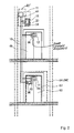
- FIG. 2 is a schematic view of an elevator with the elevator apparatus according to FIG. 1 ;
- FIG. 3 a diagrammatic representation of a comparison of a resistor parameter with a reference parameter
- FIG. 4 a time-ray that represents an operating time of the elevator apparatus
- FIG. 5 a diagrammatic representation of an alternative exemplary embodiment of an elevator apparatus with a separate monitoring-voltage source according to the present invention.
- FIG. 6 a further diagrammatic representation of another alternative exemplary embodiment with an induction current-measuring unit according to the present invention.
- FIG. 1 shows a diagrammatic representation of an elevator apparatus 1 according to the invention, which comprises a safety circuit 10 with three series-connected output-switching elements (output-switching contacts) 12 . 1 , 14 . 1 , 15 . 1 of sensors 12 , 14 , 15 , and a testing device 11 with a control unit 44 and a hardware-monitoring unit 16 .
- a sensing unit 20 of the hardware-monitoring unit 16 contains a resistance-measuring unit 34 which is composed of a current-measuring unit 30 and a voltage-measuring unit 32 .
- the elevator apparatus 1 is a part of an elevator.
- FIG. 2 shows such an elevator with the elevator apparatus according to the present invention.
- the elevator has elevator-hoistway doors 48 , 50 and a car door 52 . Closable with the car door 52 is a car 54 of the elevator which is provided for the purpose of transporting goods and persons.
- the sensors 12 , 14 are each assigned to one of the door-locking elements 86 , 88 , 90 of the elevator-hoistway doors 48 , 50 , or of the car door 52 . If one of the elevator-hoistway doors 48 , 50 , or the car door 52 , is closed and locked, the electrical output-switching contact 12 . 1 , 14 . 1 , 15 .
- a voltage is present on the safety circuit of the elevator apparatus 1 .
- This voltage causes a current-flow when the output-switching contacts 12 . 1 , 14 . 1 , 15 . 1 of all sensors 12 , 14 , 15 of the safety circuit 10 are closed.
- the control unit 44 this signals to the elevator control 45 that a movement of the car 54 is allowed.
- the control unit 44 is integrated in the elevator control 45 that is represented by means of chain-dotted lines.
- the hardware-monitoring unit 16 monitors at least one functionally relevant condition of the hardware components 18 which are formed by the sensors 12 , 14 , 15 .
- the safety circuit 10 conducts electric current when the output-switching elements of all sensors 12 , 14 , 15 of the safety circuit 10 are conductive, i.e. when the output-switching contacts 12 . 1 , 14 . 1 , 15 . 1 of the sensors 12 , 14 , 15 represented in FIGS. 1 and 2 are closed. So that in a safe state of the elevator, current can actually flow through the safety circuit 10 , the output-switching elements and the output-switching contacts 12 . 1 , 14 . 1 , 15 .
- the output-switching elements of the sensors 12 , 14 , 15 that are embodied as output-switching contacts 12 . 1 , 14 . 1 , 15 . 1 must, for example, be free of significant soiling, and free of significantly oxidized contact points, so that in the conductive state they do not form excessively high contact resistances in the safety circuit.
- the sensing unit 20 senses a resistor parameter which can be, for example, the total resistance-value 22 of the safety circuit 10 .
- the total resistance-value of the safety circuit 10 is that resistance-value which the series-connection of the output-switching contacts 12 . 1 , 14 . 1 , 15 . 1 of the sensors 12 , 14 , 15 of the safety circuit 10 has in total when all output-switching contacts of the sensors are in a closed state.
- the current-measuring unit 30 has an output 46 which is connected to an input 58 of the control unit 44 . Further, an input 60 of the current-measuring unit 30 is connected to an end 76 of the safety circuit 10 , i.e. to the sensor 12 . An output 56 of the control unit 44 is conductively connected to an end 78 of the safety circuit 10 , i.e. to the sensor 15 . Furthermore, an input 62 of the voltage-measuring unit 32 is conductively connected to the output 56 . An output 64 of the voltage-measuring unit 32 is connected to the input 58 of the control unit 44 .
- the voltage-measuring unit 32 measures a voltage that is present between the output 56 and the input 58 of the control unit 44 in the state in which the safety circuit 10 in principle conducts electric current. Furthermore, the current-measuring device 30 measures the current-magnitude of the electric current that flows through the safety circuit 20 when the safety circuit 10 is in the state in which it in principle conducts electric current, and, by means of the control unit 44 , a voltage is applied to the input 58 and to the output 56 . Should at least the output-switching contact 12 . 1 , 14 . 1 , 15 .
- the safety circuit 10 carries only a current of reduced current-magnitude, or no current at all. From the measured current-magnitude and the measured voltage, the hardware-monitoring unit 16 determines the total resistance-value 22 of the safety circuit 10 .
- the hardware-monitoring unit 16 of the testing device 11 has a comparison unit 24 which in the at-least one operating mode compares the resistor parameters, in the present case the measured total resistance-value 22 , with a reference value 26 ( FIG. 3 ).
- the reference value 26 is identical to the total resistance-value that the safety circuit 10 has with unsoiled and unoxidized output-switching contacts 12 . 1 , 14 . 1 , 15 . 1 of the sensors 12 , 14 , 15 in particular immediately after a first commissioning of the elevator apparatus.
- the reference value 26 is measured by the hardware-monitoring unit 16 , which contains a calibrating unit 28 , and stored in a memory unit 66 of the comparison unit 24 .
- the comparison unit 24 compares the measured total resistance-value 22 of the safety circuit with the reference value 26 and signals to an output unit 40 that is integrated in the hardware-monitoring unit 16 a need for maintenance of the sensors 12 , 14 , 15 when the total resistance-value 22 deviates by more than a certain percentage value from the reference value 26 .
- the output unit 40 After a receipt of the need-for-maintenance signal, by means of a telephone or radio connection the output unit 40 notifies an elevator maintenance organization or a maintenance person. The maintenance person can then remove a possible soiling and/or oxidation and/or other impairment of the output-switching contacts of the sensors 12 , 14 , 15 before a further increase in the total resistance-value of the safety circuit 10 causes an interruption of the elevator operation.
- the sensing unit 20 senses the resistor parameter, and/or the total resistance-value 22 , during all phases of the operating time in which all output-switching contacts of the sensors of the safety circuit are closed, i.e. in all phases in which the current-measuring unit detects a current-flow.
- FIG. 4 shows a time-ray which begins with a completion of the first commissioning of the elevator apparatus.
- the reference value 26 is measured at point-in-time 68 .
- the resistor parameter, or total resistance-value 22 is measured and compared with the reference value 26 .
- the hardware-monitoring unit 16 of the testing device 11 has a processing unit, a memory unit, and an operating program which is stored in the memory unit.
- the safety circuit 10 has further electrical contacts which, for example, serve to monitor a brake of the elevator.
- the elevator apparatus 1 can also be retrofitted in an already existing elevator or in existing elevator systems.
- FIGS. 5 and 6 Represented in FIGS. 5 and 6 are two alternative exemplary embodiments of an elevator apparatus. Components, characteristics, and functions that remain essentially the same are in principle indicated with the same reference numbers. However, to differentiate the exemplary embodiments, in FIGS. 5 and 6 the reference numbers are suffixed with the letters “a” and “b” respectively. The following description is essentially limited to the differences relative to the exemplary embodiment in FIGS. 1 to 4 , while for components, characteristics, and functions that remain the same, reference should be made to the description of the exemplary embodiment in FIGS. 1 to 4 .
- the elevator apparatus 1 a that is represented in FIG. 5 comprises a testing device 11 a with a control unit 44 a and a safety circuit 10 a wherein the control unit and the safety circuit preferably form a part of the elevator control 45 a of an elevator. Furthermore, the testing device 11 a comprises a hardware-monitoring unit 16 a with a sensing unit 20 a and a switching relay 70 a with two switching contacts 70 . 1 a , 70 . 2 a . During operation of the elevator, via the control unit 44 a of the elevator control 45 a a safety-circuit voltage is applied to the safety circuit 10 a .
- a current flows through the safety circuit 10 a which, for example, activates a safety relay 38 a of the control unit 44 a , which signals to the elevator control 45 a that a transportation of persons and/or goods by the elevator is possible without danger.
- the control unit 44 a has a time-measuring unit 74 which measures a period of time during which the current flows uninterruptedly through the safety circuit 10 a .
- a triggering unit 42 a of the control unit 44 a activates the hardware-monitoring unit 16 a and the switching relay 70 a with the switching contacts 70 . 1 a , 70 . 2 a .
- the switching contacts 70 . 1 a , 70 . 2 a thereupon decouple the safety circuit 10 a from the control unit 44 a and connect one end 76 a of the safety circuit 10 a with one input 80 a of the hardware-monitoring unit 16 a , and another end 78 a of the safety circuit 10 a with an output 82 a of the hardware-monitoring unit 16 a .
- a voltage that is generated by a monitoring-voltage source 84 a in the hardware-monitoring unit 16 a is applied to the safety circuit 10 a .
- a current-measuring unit 30 a and a voltage-measuring unit 32 a of the sensing unit 20 a form a resistance-measuring unit 34 a which determines a total resistance-value of the safety circuit 10 a .
- the current-measuring unit 30 a measuring the current-flow that is generated by the voltage source 84 a , the resistance-measuring unit 34 a measuring the monitoring voltage that is present on the safety circuit during the measuring operation, and the sensing unit determining from the measured current-magnitude and the measured monitoring-voltage the momentary total resistance-value of the safety circuit.
- the total resistance that is determined in a comparison unit 24 a is compared with a saved reference value, whereupon if applicable the comparison unit of an output unit 40 a signals an inadmissibly high total resistance-value.
- the switching relay decouples the safety circuit 10 a from the sensing unit 20 a and applies again to the safety circuit the safety-circuit voltage that originates from the control unit 44 a of the elevator control 45 a . If the hardware-monitoring unit 16 a is activated on account of the time period during which the safety circuit is not interrupted, a measurement of the total resistance-value takes place preferably at night, because in this time period a use of the elevator is rare.
- control unit 44 a recognizes in another manner that the elevator is not in use and thereupon causes a decoupling of the safety circuit 10 a from the safety-circuit voltage and a coupling to the monitoring-voltage source of the hardware-monitoring unit 16 a . It is further conceivable that the sensing of the total resistance-value 22 is limited to a fixed number of measurements per time unit, for example to one measurement per day at a time at which, according to experience, the elevator is hardly used.
- FIG. 6 shows a further exemplary embodiment of an elevator apparatus 1 b with a control unit 44 b , a safety circuit 10 b , and a hardware-monitoring unit 16 b with a sensing unit 20 b .
- the manner of functioning of the elevator apparatus 1 b is essentially the same as the manner of functioning of the elevator apparatus described in connection with the elevator apparatus described with FIGS. 1 and 2 .
- the sensing unit 20 b has a current-measuring unit 30 b which is embodied as an induction current-measuring unit.
Landscapes
- Maintenance And Inspection Apparatuses For Elevators (AREA)
- Elevator Control (AREA)
- Indicating And Signalling Devices For Elevators (AREA)
Priority Applications (1)
| Application Number | Priority Date | Filing Date | Title |
|---|---|---|---|
| US12/626,090 US8552738B2 (en) | 2008-11-27 | 2009-11-25 | Device for checking a safety circuit of an elevator |
Applications Claiming Priority (2)
| Application Number | Priority Date | Filing Date | Title |
|---|---|---|---|
| US11845408P | 2008-11-27 | 2008-11-27 | |
| US12/626,090 US8552738B2 (en) | 2008-11-27 | 2009-11-25 | Device for checking a safety circuit of an elevator |
Publications (2)
| Publication Number | Publication Date |
|---|---|
| US20100141267A1 US20100141267A1 (en) | 2010-06-10 |
| US8552738B2 true US8552738B2 (en) | 2013-10-08 |
Family
ID=41666592
Family Applications (1)
| Application Number | Title | Priority Date | Filing Date |
|---|---|---|---|
| US12/626,090 Expired - Fee Related US8552738B2 (en) | 2008-11-27 | 2009-11-25 | Device for checking a safety circuit of an elevator |
Country Status (8)
| Country | Link |
|---|---|
| US (1) | US8552738B2 (de) |
| EP (1) | EP2349899B1 (de) |
| CN (1) | CN102227367B (de) |
| BR (1) | BRPI0921866B1 (de) |
| ES (1) | ES2484320T3 (de) |
| PL (1) | PL2349899T3 (de) |
| SG (1) | SG171429A1 (de) |
| WO (1) | WO2010060950A1 (de) |
Cited By (8)
| Publication number | Priority date | Publication date | Assignee | Title |
|---|---|---|---|---|
| US20110272216A1 (en) * | 2009-03-04 | 2011-11-10 | Mitsubishi Electric Corporation | Elevator device and method of inspecting same |
| US20150377968A1 (en) * | 2013-02-12 | 2015-12-31 | Inventio Ag | Battery-assisted safety circuit monitoring system |
| US20180079622A1 (en) * | 2015-03-20 | 2018-03-22 | Otis Elevator Company | Elevator testing arrangement |
| US10364127B2 (en) * | 2013-12-18 | 2019-07-30 | Inventio Ag | Elevator installation safety system and method of checking same |
| US10526169B2 (en) * | 2014-12-17 | 2020-01-07 | Inventio Ag | Safety switching for an elevator system |
| US10640330B2 (en) * | 2015-06-22 | 2020-05-05 | Thyssenkrupp Elevator Ag | Safety devices, lift systems with safety devices and methods of operating lift systems with safety devices |
| EP3753893A1 (de) | 2019-06-18 | 2020-12-23 | Inventio AG | Testverfahren und vorrichtung zum testen der integrität einer aufzugssignalübertragungsleitung in einem aufzug |
| US12570500B2 (en) | 2018-06-29 | 2026-03-10 | Inventio Ag | Elevator safety switching system and method for switching between operating modes |
Families Citing this family (21)
| Publication number | Priority date | Publication date | Assignee | Title |
|---|---|---|---|---|
| FI122473B (fi) * | 2010-12-14 | 2012-02-15 | Kone Corp | Liitäntäyksikkö, kuljetusjärjestelmä sekä menetelmä |
| EP2604566B1 (de) * | 2011-12-12 | 2014-03-26 | Cedes AG | Sicherungsvorrichtung sowie Aufzugvorrichtung |
| CN104271484B (zh) * | 2012-04-20 | 2017-05-03 | 通力股份公司 | 测试设备和安全配置件 |
| TWI622548B (zh) * | 2012-12-13 | 2018-05-01 | 伊文修股份有限公司 | 用於人員輸送設備的監視裝置、人員輸送設備、以及用於監視人員輸送設備之方法 |
| EP2789563B1 (de) * | 2013-04-09 | 2015-11-04 | Kone Corporation | Aufzug mit einer Sicherungskette mit einer Reihenschaltung von Sicherheitsschalteranordnungen |
| US11016131B2 (en) * | 2016-04-29 | 2021-05-25 | Hp Indigo B.V. | Monitoring circuitry |
| WO2018019639A1 (en) * | 2016-07-28 | 2018-02-01 | Inventio Ag | Hoistway door lock with reed switches |
| DE102016117821A1 (de) * | 2016-09-21 | 2018-03-22 | Pilz Gmbh & Co. Kg | Sicherheitsschaltung zum fehlersicheren Abschalten einer gefahrbringenden technischen Anlage |
| WO2018141422A1 (en) * | 2017-01-31 | 2018-08-09 | Inventio Ag | Elevator with a monitoring arrangement for monitoring an integrity of suspension members |
| EP3403967B1 (de) * | 2017-05-15 | 2019-07-03 | KONE Corporation | Stromabschaltanordnung eines aufzugs |
| US11242226B2 (en) * | 2018-05-14 | 2022-02-08 | Otis Elevator Company | Elevator door safety control |
| DE102019206984A1 (de) * | 2018-05-31 | 2019-12-05 | Robert Bosch Engineering And Business Solutions Private Limited | Eine eingriffsfreie aufzugsüberwachungseinrichtung |
| CN109142910A (zh) * | 2018-07-11 | 2019-01-04 | 戈尔电梯(天津)有限公司 | 一种电梯门机状态监测系统及方法 |
| EP3617114A1 (de) * | 2018-08-30 | 2020-03-04 | Inventio AG | Verfahren und überwachungsvorrichtung zum überwachen einer sicherheitskettenschaltung in einer aufzuganlage |
| US10636272B2 (en) * | 2018-09-26 | 2020-04-28 | Otis Elevator Company | Time domain reflectometry for electrical safety chain condition based maintenance |
| EP3650388B1 (de) * | 2018-11-06 | 2025-08-06 | KONE Corporation | Verfahren und system zum erkennen einer fehlfunktion einer aufzugsanlage |
| IT201900006980A1 (it) * | 2019-05-17 | 2020-11-17 | Astra S R L | Sistema di controllo del funzionamento di un apparato dotato di mezzi motori controllati e regolati elettricamente |
| EP3825706B1 (de) | 2019-11-25 | 2023-09-27 | Otis Elevator Company | Elektronischer testknoten für automatische überprüfung einer sicherheitskette |
| EP4267504B1 (de) * | 2020-12-24 | 2024-11-13 | Inventio Ag | Aufzugsüberwachungssystem |
| CN115783921A (zh) * | 2022-09-20 | 2023-03-14 | 上海三菱电梯有限公司 | 安全回路触点失效检测装置及检测方法 |
| CN117142300B (zh) * | 2023-08-01 | 2025-12-26 | 巨人通力电梯有限公司 | 一种电梯门锁触点阻值检测和电压监测系统及其方法 |
Citations (7)
| Publication number | Priority date | Publication date | Assignee | Title |
|---|---|---|---|---|
| US4322712A (en) * | 1978-11-01 | 1982-03-30 | Mitsubishi Denki Kabushiki Kaisha | Elevator speed detecting apparatus |
| US4678063A (en) * | 1984-10-05 | 1987-07-07 | Mitsubishi Denki Kabushiki Kaisha | Apparatus for controlling an elevator |
| US6114847A (en) * | 1995-10-04 | 2000-09-05 | Johnson; Darrell | Connectionless signal detection device for conductive cables |
| EP1090870A1 (de) | 1999-10-08 | 2001-04-11 | Inventio Ag | Sicherheitskreis für eine Aufzugsanlage |
| US6385547B1 (en) * | 1999-09-22 | 2002-05-07 | Otis Elevator Company | Automatic monitoring of high voltage signals |
| US7084640B2 (en) * | 2004-04-08 | 2006-08-01 | Atmel Germany Gmbh | Operating and evaluation circuit of an insect sensor |
| WO2008081074A1 (en) * | 2007-01-03 | 2008-07-10 | Kone Corporation | Elevator safety device |
Family Cites Families (3)
| Publication number | Priority date | Publication date | Assignee | Title |
|---|---|---|---|---|
| FR2777087B1 (fr) | 1998-04-03 | 2000-05-05 | Otis Elevator Co | Dispositif pour localiser une panne de fermeture de porte paliere dans une installation d'ascenseur |
| DE10122204B4 (de) * | 2001-05-08 | 2008-10-09 | Otis Elevator Co., Farmington | Aufzugssicherheitssystem |
| WO2006108433A1 (en) | 2005-04-11 | 2006-10-19 | Otis Elevator Company | Safety circuit for a passenger conveyor system |
-
2009
- 2009-11-25 US US12/626,090 patent/US8552738B2/en not_active Expired - Fee Related
- 2009-11-26 ES ES09771732.6T patent/ES2484320T3/es active Active
- 2009-11-26 CN CN2009801474587A patent/CN102227367B/zh not_active Expired - Fee Related
- 2009-11-26 WO PCT/EP2009/065879 patent/WO2010060950A1/de not_active Ceased
- 2009-11-26 EP EP09771732.6A patent/EP2349899B1/de not_active Not-in-force
- 2009-11-26 SG SG2011038320A patent/SG171429A1/en unknown
- 2009-11-26 PL PL09771732T patent/PL2349899T3/pl unknown
- 2009-11-26 BR BRPI0921866-1A patent/BRPI0921866B1/pt not_active IP Right Cessation
Patent Citations (8)
| Publication number | Priority date | Publication date | Assignee | Title |
|---|---|---|---|---|
| US4322712A (en) * | 1978-11-01 | 1982-03-30 | Mitsubishi Denki Kabushiki Kaisha | Elevator speed detecting apparatus |
| US4678063A (en) * | 1984-10-05 | 1987-07-07 | Mitsubishi Denki Kabushiki Kaisha | Apparatus for controlling an elevator |
| US6114847A (en) * | 1995-10-04 | 2000-09-05 | Johnson; Darrell | Connectionless signal detection device for conductive cables |
| US6385547B1 (en) * | 1999-09-22 | 2002-05-07 | Otis Elevator Company | Automatic monitoring of high voltage signals |
| EP1090870A1 (de) | 1999-10-08 | 2001-04-11 | Inventio Ag | Sicherheitskreis für eine Aufzugsanlage |
| US7084640B2 (en) * | 2004-04-08 | 2006-08-01 | Atmel Germany Gmbh | Operating and evaluation circuit of an insect sensor |
| WO2008081074A1 (en) * | 2007-01-03 | 2008-07-10 | Kone Corporation | Elevator safety device |
| US20090321192A1 (en) * | 2007-01-03 | 2009-12-31 | Kone Corporation | Elevator safety device |
Cited By (10)
| Publication number | Priority date | Publication date | Assignee | Title |
|---|---|---|---|---|
| US20110272216A1 (en) * | 2009-03-04 | 2011-11-10 | Mitsubishi Electric Corporation | Elevator device and method of inspecting same |
| US8807285B2 (en) * | 2009-03-04 | 2014-08-19 | Mitsubishi Electric Corporation | Elevator device and method of inspecting same |
| US20150377968A1 (en) * | 2013-02-12 | 2015-12-31 | Inventio Ag | Battery-assisted safety circuit monitoring system |
| US10012696B2 (en) * | 2013-02-12 | 2018-07-03 | Inventio Ag | Battery-assisted safety circuit monitoring system |
| US10364127B2 (en) * | 2013-12-18 | 2019-07-30 | Inventio Ag | Elevator installation safety system and method of checking same |
| US10526169B2 (en) * | 2014-12-17 | 2020-01-07 | Inventio Ag | Safety switching for an elevator system |
| US20180079622A1 (en) * | 2015-03-20 | 2018-03-22 | Otis Elevator Company | Elevator testing arrangement |
| US10640330B2 (en) * | 2015-06-22 | 2020-05-05 | Thyssenkrupp Elevator Ag | Safety devices, lift systems with safety devices and methods of operating lift systems with safety devices |
| US12570500B2 (en) | 2018-06-29 | 2026-03-10 | Inventio Ag | Elevator safety switching system and method for switching between operating modes |
| EP3753893A1 (de) | 2019-06-18 | 2020-12-23 | Inventio AG | Testverfahren und vorrichtung zum testen der integrität einer aufzugssignalübertragungsleitung in einem aufzug |
Also Published As
| Publication number | Publication date |
|---|---|
| EP2349899A1 (de) | 2011-08-03 |
| EP2349899B1 (de) | 2014-04-23 |
| WO2010060950A1 (de) | 2010-06-03 |
| ES2484320T3 (es) | 2014-08-11 |
| PL2349899T3 (pl) | 2014-09-30 |
| SG171429A1 (en) | 2011-07-28 |
| CN102227367A (zh) | 2011-10-26 |
| CN102227367B (zh) | 2013-05-29 |
| US20100141267A1 (en) | 2010-06-10 |
| BRPI0921866B1 (pt) | 2019-04-24 |
| HK1160435A1 (en) | 2012-08-17 |
| BRPI0921866A2 (pt) | 2015-12-29 |
Similar Documents
| Publication | Publication Date | Title |
|---|---|---|
| US20100141267A1 (en) | Device for checking a safety circuit of an elevator | |
| US9731627B2 (en) | Capacitive sensor | |
| EP3408130B1 (de) | Anordnung mit batteriesystem zur bereitstellung elektrischer energie an ein fahrzeug | |
| US7026787B2 (en) | Method and device for determining the starting capability of a vehicle | |
| US9561767B2 (en) | Drive arrangement for driving a vehicle safety device | |
| AU2002336464B2 (en) | Controller for switch machine | |
| CN104937379B (zh) | 电容式的接近传感器 | |
| US10550998B2 (en) | Safety switch | |
| KR20180125546A (ko) | 다중 전류 센서 시스템 | |
| EP1824708A1 (de) | Kollisionserkennungsvorrichtung für ein fahrzeug | |
| US9382744B2 (en) | Method for testing the operation of an anti-trap system and diagnostic device | |
| US20170146601A1 (en) | Method and system for verification of contact operation | |
| US7719131B2 (en) | Apparatus for monitoring a supply system, in particular a motor-vehicle electrical system, and method for monitoring a supply system of this type | |
| EP2472690B1 (de) | Verfahren und Systeme mit Überwachungsschaltkreis-Konnektivität | |
| WO2002044657A3 (en) | Method for detecting faulty liquid level sensors | |
| JP2002526327A (ja) | プリテンショナー用点火素子およびシートベルト操作状態センサから成る回路装置 | |
| HK1160435B (en) | Device for checking a safety chain of an elevator | |
| JP4662757B2 (ja) | 閉電路形踏切制御子の列車検知アダプタ | |
| JP4186841B2 (ja) | 乗員検知装置 | |
| CN212658803U (zh) | 具有电流检测功能的诊断电路 | |
| CN118647565A (zh) | 无线式传感器和升降机信息收集系统 | |
| JPH02171997A (ja) | センサ故障検出装置 |
Legal Events
| Date | Code | Title | Description |
|---|---|---|---|
| AS | Assignment |
Owner name: INVENTIO AG,SWITZERLAND Free format text: ASSIGNMENT OF ASSIGNORS INTEREST;ASSIGNOR:QUINN, DANIEL;REEL/FRAME:024062/0373 Effective date: 20100202 Owner name: INVENTIO AG, SWITZERLAND Free format text: ASSIGNMENT OF ASSIGNORS INTEREST;ASSIGNOR:QUINN, DANIEL;REEL/FRAME:024062/0373 Effective date: 20100202 |
|
| STCF | Information on status: patent grant |
Free format text: PATENTED CASE |
|
| FEPP | Fee payment procedure |
Free format text: PAYOR NUMBER ASSIGNED (ORIGINAL EVENT CODE: ASPN); ENTITY STATUS OF PATENT OWNER: LARGE ENTITY |
|
| FPAY | Fee payment |
Year of fee payment: 4 |
|
| FEPP | Fee payment procedure |
Free format text: MAINTENANCE FEE REMINDER MAILED (ORIGINAL EVENT CODE: REM.); ENTITY STATUS OF PATENT OWNER: LARGE ENTITY |
|
| LAPS | Lapse for failure to pay maintenance fees |
Free format text: PATENT EXPIRED FOR FAILURE TO PAY MAINTENANCE FEES (ORIGINAL EVENT CODE: EXP.); ENTITY STATUS OF PATENT OWNER: LARGE ENTITY |
|
| STCH | Information on status: patent discontinuation |
Free format text: PATENT EXPIRED DUE TO NONPAYMENT OF MAINTENANCE FEES UNDER 37 CFR 1.362 |
|
| FP | Lapsed due to failure to pay maintenance fee |
Effective date: 20211008 |