US8534951B2 - Joint unit - Google Patents
Joint unit Download PDFInfo
- Publication number
- US8534951B2 US8534951B2 US13/061,224 US200913061224A US8534951B2 US 8534951 B2 US8534951 B2 US 8534951B2 US 200913061224 A US200913061224 A US 200913061224A US 8534951 B2 US8534951 B2 US 8534951B2
- Authority
- US
- United States
- Prior art keywords
- pressing
- pressing body
- case
- joint
- bolt
- Prior art date
- Legal status (The legal status is an assumption and is not a legal conclusion. Google has not performed a legal analysis and makes no representation as to the accuracy of the status listed.)
- Active, expires
Links
- 238000003825 pressing Methods 0.000 claims abstract description 189
- 230000007246 mechanism Effects 0.000 claims abstract description 20
- 230000009471 action Effects 0.000 claims description 5
- 230000004044 response Effects 0.000 abstract description 8
- 238000010276 construction Methods 0.000 description 20
- 230000002093 peripheral effect Effects 0.000 description 5
- XEEYBQQBJWHFJM-UHFFFAOYSA-N Iron Chemical compound [Fe] XEEYBQQBJWHFJM-UHFFFAOYSA-N 0.000 description 4
- 229910000831 Steel Inorganic materials 0.000 description 4
- 238000013459 approach Methods 0.000 description 4
- 239000010959 steel Substances 0.000 description 4
- 238000005096 rolling process Methods 0.000 description 3
- 238000006073 displacement reaction Methods 0.000 description 2
- 230000005489 elastic deformation Effects 0.000 description 2
- 229910052742 iron Inorganic materials 0.000 description 2
- 238000005452 bending Methods 0.000 description 1
- 238000009937 brining Methods 0.000 description 1
- 230000003247 decreasing effect Effects 0.000 description 1
- 230000000694 effects Effects 0.000 description 1
- 238000005286 illumination Methods 0.000 description 1
- 230000006872 improvement Effects 0.000 description 1
- 230000007257 malfunction Effects 0.000 description 1
- 238000005259 measurement Methods 0.000 description 1
- 239000002184 metal Substances 0.000 description 1
- 229910052751 metal Inorganic materials 0.000 description 1
- 238000000034 method Methods 0.000 description 1
- 230000009467 reduction Effects 0.000 description 1
- 238000009877 rendering Methods 0.000 description 1
- 239000011347 resin Substances 0.000 description 1
- 229920005989 resin Polymers 0.000 description 1
- 230000035939 shock Effects 0.000 description 1
- 238000003466 welding Methods 0.000 description 1
Images


Classifications
-
- F—MECHANICAL ENGINEERING; LIGHTING; HEATING; WEAPONS; BLASTING
- F16—ENGINEERING ELEMENTS AND UNITS; GENERAL MEASURES FOR PRODUCING AND MAINTAINING EFFECTIVE FUNCTIONING OF MACHINES OR INSTALLATIONS; THERMAL INSULATION IN GENERAL
- F16C—SHAFTS; FLEXIBLE SHAFTS; ELEMENTS OR CRANKSHAFT MECHANISMS; ROTARY BODIES OTHER THAN GEARING ELEMENTS; BEARINGS
- F16C11/00—Pivots; Pivotal connections
- F16C11/04—Pivotal connections
- F16C11/10—Arrangements for locking
- F16C11/103—Arrangements for locking frictionally clamped
- F16C11/106—Arrangements for locking frictionally clamped for ball joints
-
- F—MECHANICAL ENGINEERING; LIGHTING; HEATING; WEAPONS; BLASTING
- F16—ENGINEERING ELEMENTS AND UNITS; GENERAL MEASURES FOR PRODUCING AND MAINTAINING EFFECTIVE FUNCTIONING OF MACHINES OR INSTALLATIONS; THERMAL INSULATION IN GENERAL
- F16M—FRAMES, CASINGS OR BEDS OF ENGINES, MACHINES OR APPARATUS, NOT SPECIFIC TO ENGINES, MACHINES OR APPARATUS PROVIDED FOR ELSEWHERE; STANDS; SUPPORTS
- F16M11/00—Stands or trestles as supports for apparatus or articles placed thereon ; Stands for scientific apparatus such as gravitational force meters
- F16M11/02—Heads
- F16M11/04—Means for attachment of apparatus; Means allowing adjustment of the apparatus relatively to the stand
- F16M11/06—Means for attachment of apparatus; Means allowing adjustment of the apparatus relatively to the stand allowing pivoting
- F16M11/10—Means for attachment of apparatus; Means allowing adjustment of the apparatus relatively to the stand allowing pivoting around a horizontal axis
-
- F—MECHANICAL ENGINEERING; LIGHTING; HEATING; WEAPONS; BLASTING
- F16—ENGINEERING ELEMENTS AND UNITS; GENERAL MEASURES FOR PRODUCING AND MAINTAINING EFFECTIVE FUNCTIONING OF MACHINES OR INSTALLATIONS; THERMAL INSULATION IN GENERAL
- F16M—FRAMES, CASINGS OR BEDS OF ENGINES, MACHINES OR APPARATUS, NOT SPECIFIC TO ENGINES, MACHINES OR APPARATUS PROVIDED FOR ELSEWHERE; STANDS; SUPPORTS
- F16M11/00—Stands or trestles as supports for apparatus or articles placed thereon ; Stands for scientific apparatus such as gravitational force meters
- F16M11/02—Heads
- F16M11/04—Means for attachment of apparatus; Means allowing adjustment of the apparatus relatively to the stand
- F16M11/06—Means for attachment of apparatus; Means allowing adjustment of the apparatus relatively to the stand allowing pivoting
- F16M11/12—Means for attachment of apparatus; Means allowing adjustment of the apparatus relatively to the stand allowing pivoting in more than one direction
- F16M11/14—Means for attachment of apparatus; Means allowing adjustment of the apparatus relatively to the stand allowing pivoting in more than one direction with ball-joint
-
- F—MECHANICAL ENGINEERING; LIGHTING; HEATING; WEAPONS; BLASTING
- F16—ENGINEERING ELEMENTS AND UNITS; GENERAL MEASURES FOR PRODUCING AND MAINTAINING EFFECTIVE FUNCTIONING OF MACHINES OR INSTALLATIONS; THERMAL INSULATION IN GENERAL
- F16C—SHAFTS; FLEXIBLE SHAFTS; ELEMENTS OR CRANKSHAFT MECHANISMS; ROTARY BODIES OTHER THAN GEARING ELEMENTS; BEARINGS
- F16C11/00—Pivots; Pivotal connections
- F16C11/04—Pivotal connections
- F16C11/06—Ball-joints; Other joints having more than one degree of angular freedom, i.e. universal joints
-
- F—MECHANICAL ENGINEERING; LIGHTING; HEATING; WEAPONS; BLASTING
- F16—ENGINEERING ELEMENTS AND UNITS; GENERAL MEASURES FOR PRODUCING AND MAINTAINING EFFECTIVE FUNCTIONING OF MACHINES OR INSTALLATIONS; THERMAL INSULATION IN GENERAL
- F16C—SHAFTS; FLEXIBLE SHAFTS; ELEMENTS OR CRANKSHAFT MECHANISMS; ROTARY BODIES OTHER THAN GEARING ELEMENTS; BEARINGS
- F16C11/00—Pivots; Pivotal connections
- F16C11/04—Pivotal connections
- F16C11/10—Arrangements for locking
-
- F—MECHANICAL ENGINEERING; LIGHTING; HEATING; WEAPONS; BLASTING
- F16—ENGINEERING ELEMENTS AND UNITS; GENERAL MEASURES FOR PRODUCING AND MAINTAINING EFFECTIVE FUNCTIONING OF MACHINES OR INSTALLATIONS; THERMAL INSULATION IN GENERAL
- F16M—FRAMES, CASINGS OR BEDS OF ENGINES, MACHINES OR APPARATUS, NOT SPECIFIC TO ENGINES, MACHINES OR APPARATUS PROVIDED FOR ELSEWHERE; STANDS; SUPPORTS
- F16M11/00—Stands or trestles as supports for apparatus or articles placed thereon ; Stands for scientific apparatus such as gravitational force meters
- F16M11/20—Undercarriages with or without wheels
- F16M11/2007—Undercarriages with or without wheels comprising means allowing pivoting adjustment
- F16M11/2035—Undercarriages with or without wheels comprising means allowing pivoting adjustment in more than one direction
- F16M11/2078—Undercarriages with or without wheels comprising means allowing pivoting adjustment in more than one direction with ball-joint
-
- G—PHYSICS
- G01—MEASURING; TESTING
- G01B—MEASURING LENGTH, THICKNESS OR SIMILAR LINEAR DIMENSIONS; MEASURING ANGLES; MEASURING AREAS; MEASURING IRREGULARITIES OF SURFACES OR CONTOURS
- G01B5/00—Measuring arrangements characterised by the use of mechanical techniques
- G01B5/0002—Arrangements for supporting, fixing or guiding the measuring instrument or the object to be measured
-
- F—MECHANICAL ENGINEERING; LIGHTING; HEATING; WEAPONS; BLASTING
- F16—ENGINEERING ELEMENTS AND UNITS; GENERAL MEASURES FOR PRODUCING AND MAINTAINING EFFECTIVE FUNCTIONING OF MACHINES OR INSTALLATIONS; THERMAL INSULATION IN GENERAL
- F16M—FRAMES, CASINGS OR BEDS OF ENGINES, MACHINES OR APPARATUS, NOT SPECIFIC TO ENGINES, MACHINES OR APPARATUS PROVIDED FOR ELSEWHERE; STANDS; SUPPORTS
- F16M2200/00—Details of stands or supports
- F16M2200/02—Locking means
- F16M2200/021—Locking means for rotational movement
- F16M2200/022—Locking means for rotational movement by friction
-
- Y—GENERAL TAGGING OF NEW TECHNOLOGICAL DEVELOPMENTS; GENERAL TAGGING OF CROSS-SECTIONAL TECHNOLOGIES SPANNING OVER SEVERAL SECTIONS OF THE IPC; TECHNICAL SUBJECTS COVERED BY FORMER USPC CROSS-REFERENCE ART COLLECTIONS [XRACs] AND DIGESTS
- Y10—TECHNICAL SUBJECTS COVERED BY FORMER USPC
- Y10T—TECHNICAL SUBJECTS COVERED BY FORMER US CLASSIFICATION
- Y10T403/00—Joints and connections
- Y10T403/32—Articulated members
- Y10T403/32008—Plural distinct articulation axes
- Y10T403/32032—Plural ball and socket
-
- Y—GENERAL TAGGING OF NEW TECHNOLOGICAL DEVELOPMENTS; GENERAL TAGGING OF CROSS-SECTIONAL TECHNOLOGIES SPANNING OVER SEVERAL SECTIONS OF THE IPC; TECHNICAL SUBJECTS COVERED BY FORMER USPC CROSS-REFERENCE ART COLLECTIONS [XRACs] AND DIGESTS
- Y10—TECHNICAL SUBJECTS COVERED BY FORMER USPC
- Y10T—TECHNICAL SUBJECTS COVERED BY FORMER US CLASSIFICATION
- Y10T403/00—Joints and connections
- Y10T403/32—Articulated members
- Y10T403/32254—Lockable at fixed position
- Y10T403/32262—At selected angle
- Y10T403/32311—Ball and socket
Definitions
- the present invention relates to a joint unit comprising a holder, an arm having a joint section to be housed in the holder and a lock mechanism configured to lock the arm at a desired pivotal angle by brining the joint section into pressed contact against the inner surface of the holder.
- Patent Document 1 exists as an art relating to the joint unit having the above-described construction.
- Patent Document 2 exists as an art relating to the pressed contact.
- a spherical head section 21 formed at a base 16 of a ball joint is housed in a housing 17 against inadvertent withdrawal therefrom.
- a neck portion 22 formed integral with the spherical head section 21 is caused to project to the outside of the housing 17. Further, a pressure from a threaded bar 19 provided in a retaining portion 11 is transmitted via an attachment 18 provided inside the housing 17 to the spherical head section 21, whereby this spherical head section 21 is brought into pressed contact against the inner surface of the housing 17.
- the pivotal angle of the base 16 relative to the housing 17 can be locked as desired.
- Patent Document 2 includes: three gripping portions 11A, 11B, 11C which come into contact with a cylindrical outer peripheral surface 101 of an object to be gripped (“gripped object” hereinafter) 100 to be deformed toward the center of the gripped object 100, thus gripping this object 100; a first member 21, plate-like second members 22A, 22B pivotally jointed to the opposed ends of the first member 21; cylindrical members 23A, 23B provided at the ends of the second members 22A, 22B; a ball 26 disposed between the cylindrical member 23A and the gripping portion 11A: and a male screw member 43 configured to cause a pressure generated by an operation of a hexagonal wrench 40 to be applied to the first member 21.
- a male screw member 43 configured to cause a pressure generated by an operation of a hexagonal wrench 40 to be applied to the first member 21.
- the second member 22A and the second member 22B are housed under flexed conditions thereof within a flexed-member accommodating hole 33.
- the pressure from the male screw member 43 is applied to the first member 21.
- the force from this first member 21 displaces the second member 22A and the cylindrical member 23, as a result of which the three gripping portions 11A, 11B, 11C are brought into pressed contact with the gripped object 100 for gripping this object 100.
- the end portion of the cylindrical housing (corresponding to a “holder” provided in the present invention) is formed with a reduced diameter, thus forming a retaining portion for the spherical head portion (corresponding to a “joint section” provided in the present invention).
- the pressing force from the threaded bar (corresponding to a portion of a “lock mechanism” provided in the present invention) is caused to be applied via the attachment to the spherical head portion, such that this spherical head portion is brought into pressed contact against the inner surface of the retaining portion.
- the base and the housing are brought into a locked state, thereby to maintain an angle relative to each other.
- Patent Document 2 it is conceivable to employ a lock arrangement configured to grip an object with a plurality of gripping portions.
- the construction disclosed in Patent Document 2 involves a large number of parts, thus inviting cost increase and great trouble in its assembly. In these respects, it was believed that employing this construction would not seem preferable or attractive.
- the object of the present invention is to configure a joint unit in a reasonable manner, which does not invite disadvantageous enlargement or operational failure of the mechanism used for locking the pivotal angle of the arm relative to the holder.
- a joint unit comprising a holder, an arm having a joint section to be housed in the holder and a lock mechanism configured to lock the arm at a desired pivotal angle by bringing the joint section into pressed contact against the inner surface of the holder,
- said lock mechanism includes, within said holder, a first pressing body having a round cross section and configured for receiving a pressing force from a clamp, a second pressing body having a round cross section and placed in contact with the first pressing body for receiving the pressing force therefrom and a pressure block configured for causing the force from either the first pressing body or the second pressing body to be applied to the joint section for bringing this joint section into pressed contact with the holder inner surface.
- the construction can omit such component such as a screw to be disposed under the posture along the direction for applying the pressure to the pressure block.
- the pressing force can be transmitted via the respective outer faces thereof which are formed round, such that during the application of the pressing force, each body can pivot and can also readily pivot upon release of the pressing force applied thereto. Consequently, there has been realized a joint unit which does not invite any malfunction of the mechanism used for locking of the pivotal angle of the arm relative to the holder.
- the joint unit includes a cylindrical case that houses the pressure block while allowing movement thereof along the direction of the axis and that forms an inside space for accommodating the first pressing body and the second pressing body;
- said clamp is configured such that a rotary operational portion is provided in a bolt for threading engagement with a female thread portion formed in said case, and said first pressing body and said second pressing body are maintained under a relative positional relationship with each other when a leading end of the bolt of the clamp is in agreement with an inner wall surface of said case.
- the relative positional relationship between the first pressing body and the second pressing body is maintained with setting of a cross sectional dimension of the first pressing body, a cross sectional dimension of the second pressing body and a dimension from one face of the pressure block on the side of the inner space to a further face thereof opposed thereto in the direction of the axis.
- the joint unit further includes a first retaining member for retaining said first pressing body and a second retaining member for retaining said second pressing body; and the pressing force from said clamp is applied to either one of said first and second retaining members in a direction for bringing said first pressing body and said second pressing body into the pressed contact with each other.
- FIG. 1 is a perspective view of a measuring instrument
- FIGS. 2( a ) and 2 ( b ) are sides views of the measuring instrument and a section view of a joint unit
- FIGS. 3( a ) and 3 ( b ) are section views of the joint unit showing the positional relationships between the first pressing body and the second pressing body under a locked state and an unlocked state, respectively,
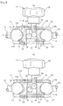
- FIGS. 4( a ) and 4 ( b ) are section views showing the joint unit under the locked state and the unlocked state as seen along the direction of the case axis,
- FIG. 5 is a section view of a joint unit according to a further embodiment (a).
- FIG. 6 is a section view of a joint unit according to a further embodiment (b).
- a measuring instrument is constructed by connecting in series, a base unit B to be supported on a level block or a table, a joint unit J and a gauge unit G of a dial gauge type.
- the base unit B When using this measuring instrument, first the base unit B will be fixedly stuck to the level block or table formed of iron by means of magnetic force of a magnet. Then, under this condition, the base unit B and the gauge unit G will be set to a relative positional relationship with each other. Thereafter, this relative positions of and between the base unit B and the gauge unit G will be fixed by means of the joint unit J. Then, the terminal end of a contact shoe 4 of the gauge unit G will be placed into contact with the outer surface of an object to be measured (“measured object” hereinafter) such as a work or a tool supported to the level block or table via a jig or the like, so as to allow reading of a measured value from an indicator 5 A of the gauge unit G.
- an object to be measured such as a work or a tool supported to the level block or table via a jig or the like
- the base unit B includes a handle 2 attached to an outer surface of a case 1 .
- the position of the magnet (a permanent magnet, not shown) inside the case 1 is varied, whereby the base unit B can be switched over between a state where the unit B is fixedly and magnetically stuck to the iron table and a state where the unit B is released from the magnetic attraction.
- the gauge unit G includes a gauge housing 3 supported to the joint unit J via a shock-absorbing mechanism, the shaft or bar-like contact shoe 4 provided to this gauge housing 3 , and a dial displaying section 5 formed in the gauge housing 3 .
- a spherical portion 4 A is formed at the outer terminal end of the contact shoe 4 . The amount of displacement of the contact shoe 4 in the axial direction when the spherical portion 4 A is brought into contact with the measured object is given as a mechanical or physical rotational amount to the indicator 5 A of the dial displaying section 5 .
- the shock-absorbing mechanism integrally includes a plate spring portion 8 formed by bending a portion of a block-like frame 7 and an adjustment bolt 9 threaded to the frame 7 to be rotatably operated by a grip 9 A.
- an initial elastic deformation amount can be set by bringing the leading end of the adjustment bolt 9 into contact with the free end of the plate spring portion 8 by a rotational operation on the grip 9 A.
- an amount of play in the measuring direction will be provided by means of elastic deformation of the plate spring portion 8 .
- the joint unit J includes holders 11 , 12 at the opposed ends of a case 10 comprising a cylindrical steel member and a lock mechanism L provided at the intermediate portion of this case 10 .
- one holder 11 is formed as a separate member (made of steel) rotatably supported to the case 10 whereas the other holder 12 is formed integrally with the case 10 .
- the one holder 11 houses therein a ball-like joint section 14 provided at the base of an arm 13 to be connected to the base unit B, whereas the other holder 12 houses therein a ball-like joint section 14 provided at a base end of an arm 13 to be connected to the gauge unit G.
- the arm 13 has a bolt-like construction forming a thread groove in its circumference.
- the one arm 13 will be threaded and fixed to the case 1 of the base unit B with a lock nut 13 N and the other arm 13 will be threaded and fixed to the frame 7 of the gauge unit G with a lock nut 13 N, thus forming the joined and fixed assembly.
- the outer ends of the holders 11 , 12 are reduced in their diameters, thus forming retaining portions for the joint sections 14 . Further, on the inner sides of these outer ends, there are formed holder inner surfaces 11 S, 12 S provided in the form of concave surfaces having a radius equal to the radius of the joint sections 14 . Further, at a portion of the periphery of the opening of the holder 11 , 12 into which the arm 13 is to be inserted, there is formed along the radial direction a cutout groove 11 T, 12 T into which the arm 13 comes into engagement. As the arm 13 comes into engagement with this cutout groove 11 T, 12 T, there is obtained a large pivotal angle.
- the case axis X is assumed to be present at the center position (in agreement with the center portion of the inner peripheral face) of the outer periphery of the case 10 .
- the outer peripheral face of this case 10 has a reduced diameter at the portion thereof where the holder 11 is to be disposed.
- a sleeve 11 A formed integrally with the holder 11 is engaged externally; and between this sleeve 11 A and the case 10 , there is disposed an engaging member 15 for providing retaining function therebetween.
- the holder 11 is supported to be freely pivotable about the case axis X, with the holder 11 being maintained in its position along the direction of the case axis X relative to the case 10 .
- the lock mechanism L includes a roller-like first pressing body 21 provided inside the case for receiving a pressing force from a clamp Lc, a roller-like second pressing body 22 for receiving the pressing force from the first pressing body 21 , a pressure block 16 provided on the side of the gauge unit for receiving the pressing force from the first pressing body 21 , and a further pressure block 16 provided on the side of the base unit for receiving the pressing force from the second pressing body 22 . Further, at a position inside the case 10 in opposition to the clamp Lc, there is provided a plate 23 for supporting the second pressing body 22 , with the plate 23 being fixed to the inner surface of the case 10 by means of such technique as bonding or welding or pin-engagement with the case 10 .
- the clamp Lc includes a bolt 18 threaded with the female thread portion formed in the case 10 under a posture perpendicular to the case axis X, and a knob 19 as a rotary operational portion which manually rotates the bolt 18 .
- the first pressing body 21 and the second pressing body 22 are provided in the form of “rollers” using steel members having a round cross sectional shape.
- Both of the two pressure blocks 16 are provided in the form of “pistons” as a whole using metal or resin. And, these blocks 16 are engaged within the case 10 to be movable along the case axis X.
- the above-described dimension S becomes the “distance” along the direction of the case axis X between those faces of the pair of pressure blocks 16 which are opposed to each other on the side of the inner space of the case, under the condition that the pressure applied to the first pressing body 21 from the bolt 18 of the clamp Lc is released.
- the first pressing body 21 and the second pressing body 22 are provided in the form of rollers and the plate 23 is provided as being fixed to the inner face of the case 10 , the inconvenience of inadvertent rolling action of each body 21 , 22 about the case axis X within the case is avoided.
- the dimensional relationship is set such that the above-described dimension S is smaller than the sum of the diameter (2r) of the first pressing body 21 and the diameter (2r) of the second pressing body 22 (S ⁇ 4r). And, the dimensional relationship is set also such that the above-described dimension H is smaller than the sum of the diameter (2r) of the first pressing body 21 and the diameter (2r) of the second pressing body 22 (H ⁇ 4r).
- the dimension S agrees with the dimension of the plate 23 in the direction along the case axis X.
- the dimension H corresponds to the distance between the surface position of the plate 23 and the position of the opposed ends of the first pressing body 1 contacting the inner surface of the case 10 opposed thereto, under the condition where the bolt 18 of the clamp Lc is in agreement with the inner wall surface of the case 10 .
- the dimension W corresponds to the length of the longitudinally movable area of the second pressing body 22 , under the condition where the bolt 18 of the clamp Lc is in agreement with the inner wall surface of the case 10 .
- the condition of the relative positional relationship being maintained is established through combination of the following conditions. Namely, while the first pressing body 21 contacts the inner face of the case 10 to have its longitudinal movement thereof restricted, this first pressing body contacts the second pressing body 22 or the pressure block 16 on the gauge unit side. While the second pressing body 22 contacts the inner face of the case 10 to have its longitudinal movement thereof restricted, this second pressing body 22 contacts the first pressing body 21 or the plate 23 or the pressure block 16 on the base unit side.
- the first pressing body 21 and the second pressing body 22 will revolve along the respective outer peripheral surfaces thereof, in the course of which each body 21 , 22 will apply a force to the pressure block 16 in contact therewith in the direction of increasing the distance between the two pressure blocks 16 (the distance along the case axis X).
- the joint sections 14 to which the pressing forces from the pressure blocks 16 are being applied are pressed against the holder inner surfaces 11 S, 12 S, thus reaching a locked state for fixing the arms 13 at the respective desired pivotal angles.
- rotational movement of the holder 11 about the case axis X is prevented, thus being locked to the case 10 .
- the pressing force from the clamp Lc is transmitted from the first pressing body 21 having a round cross section to the second pressing body 22 also having a round cross section. Therefore, in comparison with a different construction wherein the pressing force from the clamp Lc is transmitted to a slidable intermediate member, the above construction does not invite operational failure and allows smooth operation as well as reliable and speedy locking and unlocking actions.
- the present invention may be embodied as follows, alternatively to the foregoing embodiment (in the following discussion of other embodiments, components having the same functions as those in the foregoing embodiment are denoted with same reference numerals or marks as those used in the foregoing embodiment).
- a joint unit J includes a holder 12 at one terminal end of a cylindrical case 10 and at the other terminal end of the case 10 , there is formed a flat guide face 10 G disposed normal to the case axis X. And, on the side of this terminal end, an opening 10 S is formed. Also on this other terminal end side of the case 10 , there is disposed a first retaining member 31 with which a terminal end of the guide face 10 G is placed in contact.
- the first retaining member 31 defines a recess 31 A in which the roller-like first pressing body 21 is engaged and supported. Further, this first retaining member 31 defines a thread hole formed coaxial with an operational axis Y thereof extending parallel with the guide face 10 G.
- the holder 12 holds therein a ball-like joint section 14 formed at the base end of the arm 13 .
- the holder 12 holds also the pressure block 16 for applying a pressing force to this joint section 14 and a second retaining member 32 with allowing movements thereof along the case axis X.
- the second retaining member 32 defines a recess 32 A in which the roller-like second pressing body 22 is engaged and supported.
- the first pressing body 21 and the second pressing body 22 are disposed under a positional relationship shown in the same figure wherein the respective outer peripheries thereof contact each other.
- the bolt 18 of the clamp Lc of the lock mechanism L extends through the case 10 and is threaded into the thread hole of the first retaining member 31 .
- the first retaining member 31 is displaced upward along the operational axis Y while sliding against the guide face 10 G.
- the first pressing body 21 comes into pressed contact with the second pressing body 22 and the pressing force is transmitted from the second pressing body 22 to the second retaining member 32 and then to the pressure block 16 , respectively along the case axis X.
- the joint section 14 becomes pressed against the holder inner surface 12 S, thus reaching a locked state.
- the bolt 18 of the clamp Lc is placed in threaded engagement with the first retaining member 31 .
- a joint unit J includes a pair of holders 11 , 12 at opposed ends of the cylindrical case 10 and each holder 11 , 12 holds therein a ball-like joint section 14 connected to the arm 13 . Further, the case 10 houses therein a pair of pressure blocks 16 for applying pressing force to the joint sections 14 , with the blocks 16 being movable along the case axis X.
- This case 10 defines, at an intermediate portion thereof, a female thread portion in which the bolt 18 of the clamp Lc is threaded under a posture normal to the case axis X.
- the case 10 houses therein a roller-like first pressing body 21 for receiving a pressing force from the bolt 18 .
- the mutually opposed faces of the pair of pressure blocks 16 form second pressing bodies 22 for coming into contact with the first pressing body 21 .
- Each second pressing body 22 is provided in the form of a roller having a portion thereof removed and has an incomplete round or circular cross section.
- the first pressing body 21 and the second pressing bodies 22 are placed under the positional relationship with these members contacting each other.
- a pressing force is applied from the leading end of the bolt 18 to the first pressing body 21 and at the same time, a pressing force is applied from this first pressing body 21 to the pair of second pressing bodies 22 placed in contact therewith.
- each of the pair of second pressing bodies 22 applies a pressing force to each pressure block 16 corresponding thereto.
- the joint sections 14 are pressed against the holder inner surfaces 11 S, 12 S respectively, thus reaching a locked state.
- the first pressing body 21 and the second pressing body 22 have a same length. Instead of this, it is possible to employ pressing bodies of different lengths, such as the second pressing body 22 having a longer length that the first pressing body 21 . Or, it is also possible to employ “balls” made of steel or the like as the first pressing body 21 and the second pressing body 22 .
- a member that effects rotation or rolling in two-dimensional manner can be used.
- a bar-like pivot portion may be formed at the base end of the arm. And, this pivot portion is supported to the holder and the pressure block is placed in contact with the outer peripheral portion of the pivot portion, thereby providing a locking action.
- the joint unit can include an arm only at on terminal end of the case.
- This joint unit can be used not only for a measuring instrument, but for locking the posture of a level block of a tripod used for photographing by a camera or at a joint section for supporting a lamp for illumination.
- the present invention can be used as joint units in general using a lock mechanism which is locked by a pressing force from a clamp.
Landscapes
- Engineering & Computer Science (AREA)
- General Engineering & Computer Science (AREA)
- Mechanical Engineering (AREA)
- Physics & Mathematics (AREA)
- General Physics & Mathematics (AREA)
- Pivots And Pivotal Connections (AREA)
- Clamps And Clips (AREA)
Applications Claiming Priority (3)
| Application Number | Priority Date | Filing Date | Title |
|---|---|---|---|
| JP2008-228715 | 2008-09-05 | ||
| JP2008228715A JP5172551B2 (ja) | 2008-09-05 | 2008-09-05 | ジョイントユニット |
| PCT/JP2009/065518 WO2010027056A1 (fr) | 2008-09-05 | 2009-09-04 | Unité de joint |
Publications (2)
| Publication Number | Publication Date |
|---|---|
| US20110188925A1 US20110188925A1 (en) | 2011-08-04 |
| US8534951B2 true US8534951B2 (en) | 2013-09-17 |
Family
ID=41797220
Family Applications (1)
| Application Number | Title | Priority Date | Filing Date |
|---|---|---|---|
| US13/061,224 Active 2029-12-08 US8534951B2 (en) | 2008-09-05 | 2009-09-04 | Joint unit |
Country Status (7)
| Country | Link |
|---|---|
| US (1) | US8534951B2 (fr) |
| EP (1) | EP2333393B1 (fr) |
| JP (1) | JP5172551B2 (fr) |
| KR (1) | KR101590052B1 (fr) |
| CN (1) | CN102144119B (fr) |
| TW (1) | TWI484112B (fr) |
| WO (1) | WO2010027056A1 (fr) |
Cited By (8)
| Publication number | Priority date | Publication date | Assignee | Title |
|---|---|---|---|---|
| US20110020055A1 (en) * | 2009-07-22 | 2011-01-27 | Ryan Kallas | Adjustable joint for microphone |
| US20150258647A1 (en) * | 2014-03-11 | 2015-09-17 | Erowa Ag | Coupling Device For A Manipulator |
| US9415520B2 (en) * | 2014-08-11 | 2016-08-16 | Swivel-Link, LLC | Swivel link for mounting end of arm tooling |
| US20160368429A1 (en) * | 2015-06-22 | 2016-12-22 | Havis, Inc. | Vehicle mounting system |
| US20180037172A1 (en) * | 2016-08-05 | 2018-02-08 | MotoCrane, LLC | Releasable vehicular camera mount |
| US10274130B2 (en) * | 2012-01-08 | 2019-04-30 | De-Sta-Co Europe Gmbh | Carrier device |
| US20190168683A1 (en) * | 2016-08-25 | 2019-06-06 | Hong Wang | Adjustable electronic device mount |
| US11667248B2 (en) | 2021-01-12 | 2023-06-06 | Havis, Inc. | Vehicle mounting system |
Families Citing this family (12)
| Publication number | Priority date | Publication date | Assignee | Title |
|---|---|---|---|---|
| GB2492418A (en) * | 2011-07-01 | 2013-01-02 | Tamar Clarke | An articulated infant monitor stand |
| US8572849B1 (en) * | 2011-09-20 | 2013-11-05 | Donald P. Clark | System and method of connecting surfaces in an irregular space or measuring an irregular space |
| EP2761220B1 (fr) * | 2011-09-26 | 2018-12-26 | Access Products Group LLC | Articulation ajustable pour microphone |
| DE102013205700B4 (de) * | 2013-03-28 | 2018-05-09 | 9.Solutions Technology Co., Limited | Gelenkarm |
| CN104279411B (zh) * | 2013-07-02 | 2017-08-04 | 深圳一电科技有限公司 | 摄像机固定装置 |
| WO2018038755A1 (fr) * | 2016-08-25 | 2018-03-01 | Hong Wang | Support réglable pour dispositif électronique |
| KR101777707B1 (ko) * | 2017-01-24 | 2017-09-13 | 손순호 | 스위블 링크 |
| JP6540737B2 (ja) * | 2017-03-23 | 2019-07-10 | ヤマハ株式会社 | 固定部材、および固定部材を備える伸縮部材 |
| US10866256B2 (en) * | 2018-07-20 | 2020-12-15 | George V. Zusman | Universal sensor mount |
| WO2020023040A1 (fr) * | 2018-07-26 | 2020-01-30 | Hewlett-Packard Development Company, L.P. | Supports magnétiques à axes multiples |
| USD928220S1 (en) * | 2020-04-29 | 2021-08-17 | Andy Liang | Gimbal spherical bracket |
| US11572976B1 (en) | 2021-05-17 | 2023-02-07 | The United States Of America As Represented By The Secretary Of The Navy | Multiple angle pivoting placement (MAPP) stand |
Citations (16)
| Publication number | Priority date | Publication date | Assignee | Title |
|---|---|---|---|---|
| US4236844A (en) * | 1977-04-21 | 1980-12-02 | Gebr. Berchtold | Joint support structure |
| US4320884A (en) * | 1979-03-05 | 1982-03-23 | Bengt Leo | Tripod arm |
| US4402481A (en) * | 1981-02-27 | 1983-09-06 | Mitutoyo Mfg. Co., Ltd. | Articulated device for service component |
| US4431329A (en) * | 1980-02-15 | 1984-02-14 | Baitella Carlo | Articulated support stand |
| US4491435A (en) * | 1983-07-18 | 1985-01-01 | Automated Medical Products Corporation | Jointed stand |
| JPS6215619U (fr) | 1985-07-11 | 1987-01-30 | ||
| JPS63280911A (ja) | 1987-05-08 | 1988-11-17 | Kanetsuu Kogyo Kk | 自在支持装置 |
| JPH0395776U (fr) | 1990-01-22 | 1991-09-30 | ||
| US5092551A (en) * | 1988-12-09 | 1992-03-03 | Tekusa Ag | Articulated stand |
| US5261590A (en) * | 1990-06-27 | 1993-11-16 | Danny Tsai | Structure of soldering system with solder wire automatic feeding mechanism |
| US5419522A (en) * | 1992-05-06 | 1995-05-30 | New Focus, Inc. | Universal optical mount |
| US5681018A (en) * | 1994-03-02 | 1997-10-28 | Hoftman; Moshe M. | Operating room tray system |
| JP2004052911A (ja) | 2002-07-19 | 2004-02-19 | Toshio Tomioka | 自在継手及びこの自在継手を用いた保持装置 |
| JP2006123105A (ja) | 2004-10-29 | 2006-05-18 | Daishowa Seiki Co Ltd | 把握装置 |
| US20090065671A1 (en) * | 2003-12-22 | 2009-03-12 | Harald Burgstaller | Adjusting device and fixing device |
| US7717938B2 (en) * | 2004-08-27 | 2010-05-18 | Depuy Spine, Inc. | Dual rod cross connectors and inserter tools |
Family Cites Families (5)
| Publication number | Priority date | Publication date | Assignee | Title |
|---|---|---|---|---|
| DE9011338U1 (fr) * | 1990-08-02 | 1990-10-04 | Kuerbi & Niggeloh Bilora Gmbh, 5608 Radevormwald, De | |
| FR2679968A1 (fr) * | 1991-08-01 | 1993-02-05 | Pflieger Roger | Dispositif de blocage d'une rotule avec mouvement souple. |
| CN2503305Y (zh) * | 2001-08-10 | 2002-07-31 | 李黄权 | 改良结构的万向滚珠 |
| CN2515505Y (zh) * | 2001-09-07 | 2002-10-09 | 李黄权 | 万向滚珠的圆珠座 |
| CN1508468A (zh) * | 2002-12-14 | 2004-06-30 | 庄儒桂 | 可任意调节支撑方向的支撑座 |
-
2008
- 2008-09-05 JP JP2008228715A patent/JP5172551B2/ja active Active
-
2009
- 2009-09-04 CN CN200980134762.8A patent/CN102144119B/zh active Active
- 2009-09-04 WO PCT/JP2009/065518 patent/WO2010027056A1/fr active Application Filing
- 2009-09-04 US US13/061,224 patent/US8534951B2/en active Active
- 2009-09-04 EP EP09811581.9A patent/EP2333393B1/fr active Active
- 2009-09-04 KR KR1020117003914A patent/KR101590052B1/ko active IP Right Grant
- 2009-09-04 TW TW098130013A patent/TWI484112B/zh active
Patent Citations (16)
| Publication number | Priority date | Publication date | Assignee | Title |
|---|---|---|---|---|
| US4236844A (en) * | 1977-04-21 | 1980-12-02 | Gebr. Berchtold | Joint support structure |
| US4320884A (en) * | 1979-03-05 | 1982-03-23 | Bengt Leo | Tripod arm |
| US4431329A (en) * | 1980-02-15 | 1984-02-14 | Baitella Carlo | Articulated support stand |
| US4402481A (en) * | 1981-02-27 | 1983-09-06 | Mitutoyo Mfg. Co., Ltd. | Articulated device for service component |
| US4491435A (en) * | 1983-07-18 | 1985-01-01 | Automated Medical Products Corporation | Jointed stand |
| JPS6215619U (fr) | 1985-07-11 | 1987-01-30 | ||
| JPS63280911A (ja) | 1987-05-08 | 1988-11-17 | Kanetsuu Kogyo Kk | 自在支持装置 |
| US5092551A (en) * | 1988-12-09 | 1992-03-03 | Tekusa Ag | Articulated stand |
| JPH0395776U (fr) | 1990-01-22 | 1991-09-30 | ||
| US5261590A (en) * | 1990-06-27 | 1993-11-16 | Danny Tsai | Structure of soldering system with solder wire automatic feeding mechanism |
| US5419522A (en) * | 1992-05-06 | 1995-05-30 | New Focus, Inc. | Universal optical mount |
| US5681018A (en) * | 1994-03-02 | 1997-10-28 | Hoftman; Moshe M. | Operating room tray system |
| JP2004052911A (ja) | 2002-07-19 | 2004-02-19 | Toshio Tomioka | 自在継手及びこの自在継手を用いた保持装置 |
| US20090065671A1 (en) * | 2003-12-22 | 2009-03-12 | Harald Burgstaller | Adjusting device and fixing device |
| US7717938B2 (en) * | 2004-08-27 | 2010-05-18 | Depuy Spine, Inc. | Dual rod cross connectors and inserter tools |
| JP2006123105A (ja) | 2004-10-29 | 2006-05-18 | Daishowa Seiki Co Ltd | 把握装置 |
Non-Patent Citations (3)
| Title |
|---|
| International Preliminary Report mailed on Apr. 14, 2011 in the corresponding International application No. PCT/JP2009/065518. |
| International Search Report mailed on Oct. 6, 2009 for the corresponding International patent application No. PCT/JP2009/065518. |
| Office Action issued on Aug. 30, 2012 in the corresponding Japanese Priority Application No. 2008-228715 (and English translation). |
Cited By (13)
| Publication number | Priority date | Publication date | Assignee | Title |
|---|---|---|---|---|
| US8894316B2 (en) * | 2009-07-22 | 2014-11-25 | Music Express, Llc | Adjustable joint for microphone |
| US20110020055A1 (en) * | 2009-07-22 | 2011-01-27 | Ryan Kallas | Adjustable joint for microphone |
| US10274130B2 (en) * | 2012-01-08 | 2019-04-30 | De-Sta-Co Europe Gmbh | Carrier device |
| US9937595B2 (en) * | 2014-03-11 | 2018-04-10 | Erowa Ag | Coupling device for a manipulator |
| US20150258647A1 (en) * | 2014-03-11 | 2015-09-17 | Erowa Ag | Coupling Device For A Manipulator |
| US9415520B2 (en) * | 2014-08-11 | 2016-08-16 | Swivel-Link, LLC | Swivel link for mounting end of arm tooling |
| US20160368429A1 (en) * | 2015-06-22 | 2016-12-22 | Havis, Inc. | Vehicle mounting system |
| US20180037172A1 (en) * | 2016-08-05 | 2018-02-08 | MotoCrane, LLC | Releasable vehicular camera mount |
| US10479288B2 (en) * | 2016-08-05 | 2019-11-19 | MotoCrane, LLC | Releasable vehicular camera mount |
| US20190168683A1 (en) * | 2016-08-25 | 2019-06-06 | Hong Wang | Adjustable electronic device mount |
| US10583790B2 (en) * | 2016-08-25 | 2020-03-10 | Daniel Cotton | Adjustable electronic device mount |
| US11667248B2 (en) | 2021-01-12 | 2023-06-06 | Havis, Inc. | Vehicle mounting system |
| US11926264B2 (en) | 2021-01-12 | 2024-03-12 | Havis, Inc. | Vehicle mounting system |
Also Published As
| Publication number | Publication date |
|---|---|
| KR101590052B1 (ko) | 2016-01-29 |
| EP2333393A1 (fr) | 2011-06-15 |
| KR20110083593A (ko) | 2011-07-20 |
| JP2010060111A (ja) | 2010-03-18 |
| TW201013084A (en) | 2010-04-01 |
| CN102144119A (zh) | 2011-08-03 |
| EP2333393B1 (fr) | 2013-05-15 |
| CN102144119B (zh) | 2014-10-08 |
| TWI484112B (zh) | 2015-05-11 |
| US20110188925A1 (en) | 2011-08-04 |
| WO2010027056A1 (fr) | 2010-03-11 |
| EP2333393A4 (fr) | 2011-08-24 |
| JP5172551B2 (ja) | 2013-03-27 |
Similar Documents
| Publication | Publication Date | Title |
|---|---|---|
| US8534951B2 (en) | Joint unit | |
| US7765897B2 (en) | Ratchet wrench | |
| US8443702B2 (en) | Torque wrench | |
| CA2611505C (fr) | Cintreuse et procede | |
| US8294815B2 (en) | Camera support device | |
| JP2006214559A (ja) | 多関節アームとフレキシブルチューブアーム併用構造の空中位置決めスタンド | |
| US6371425B2 (en) | Articulated mechanism | |
| US8333527B2 (en) | Mechanical double joint system | |
| US20090301263A1 (en) | Self-adjustable universal ratchet spanner | |
| JP2002059294A (ja) | クランプ装置 | |
| JP3214645U (ja) | チューブ用クランプ装置 | |
| JP6945901B1 (ja) | 固定具 | |
| US20230228552A1 (en) | Angle measurement device with attachment to pipe, conduit or cylindrical workpiece | |
| TWM438351U (en) | Improved ratchet wrench structure | |
| US9341472B2 (en) | Finger grip spirit level | |
| TWI680843B (zh) | 拆卸工具 | |
| US11441726B2 (en) | Connection assembly and robot having the same | |
| TWM325901U (en) | Torsion wrench with digital display | |
| JP2023035420A (ja) | 固定具 | |
| JP2006334736A (ja) | 屈折自在アーム | |
| JP3826341B2 (ja) | トルク測定器のソケット | |
| JPH0746465Y2 (ja) | 単能型トルクレンチ | |
| TWM554144U (zh) | 管件的夾管裝置 |
Legal Events
| Date | Code | Title | Description |
|---|---|---|---|
| AS | Assignment |
Owner name: BIG ALPHA CO., INC., JAPAN Free format text: ASSIGNMENT OF ASSIGNORS INTEREST;ASSIGNORS:KOMINE, TSUYOSHI;DOI, MASAYUKI;REEL/FRAME:026128/0007 Effective date: 20110401 |
|
| STCF | Information on status: patent grant |
Free format text: PATENTED CASE |
|
| FEPP | Fee payment procedure |
Free format text: PAYOR NUMBER ASSIGNED (ORIGINAL EVENT CODE: ASPN); ENTITY STATUS OF PATENT OWNER: LARGE ENTITY |
|
| FPAY | Fee payment |
Year of fee payment: 4 |
|
| AS | Assignment |
Owner name: BIG DAISHOWA CO., LTD., JAPAN Free format text: ASSIGNMENT OF ASSIGNORS INTEREST;ASSIGNOR:BIG ALPHA CO., INC.;REEL/FRAME:044473/0251 Effective date: 20171128 Owner name: BIG ALPHA CO., INC., JAPAN Free format text: CHANGE OF ADDRESS;ASSIGNOR:BIG ALPHA CO., INC.;REEL/FRAME:044921/0128 Effective date: 20171128 |
|
| MAFP | Maintenance fee payment |
Free format text: PAYMENT OF MAINTENANCE FEE, 8TH YEAR, LARGE ENTITY (ORIGINAL EVENT CODE: M1552); ENTITY STATUS OF PATENT OWNER: LARGE ENTITY Year of fee payment: 8 |
|
| AS | Assignment |
Owner name: BIG DAISHOWA CO., LTD., JAPAN Free format text: CHANGE OF ADDRESS;ASSIGNOR:BIG DAISHOWA CO., LTD.;REEL/FRAME:058964/0038 Effective date: 20211210 |
|
| AS | Assignment |
Owner name: BIG DAISHOWA CO., LTD., JAPAN Free format text: CHANGE OF ADDRESS;ASSIGNOR:BIG DAISHOWA CO., LTD.;REEL/FRAME:059218/0742 Effective date: 20220221 |