US8508658B2 - Electronic apparatus - Google Patents
Electronic apparatus Download PDFInfo
- Publication number
- US8508658B2 US8508658B2 US13/071,407 US201113071407A US8508658B2 US 8508658 B2 US8508658 B2 US 8508658B2 US 201113071407 A US201113071407 A US 201113071407A US 8508658 B2 US8508658 B2 US 8508658B2
- Authority
- US
- United States
- Prior art keywords
- operation member
- zoom
- neutral position
- electronic apparatus
- spring
- Prior art date
- Legal status (The legal status is an assumption and is not a legal conclusion. Google has not performed a legal analysis and makes no representation as to the accuracy of the status listed.)
- Expired - Fee Related, expires
Links
Images


Classifications
-
- H—ELECTRICITY
- H04—ELECTRIC COMMUNICATION TECHNIQUE
- H04N—PICTORIAL COMMUNICATION, e.g. TELEVISION
- H04N23/00—Cameras or camera modules comprising electronic image sensors; Control thereof
- H04N23/60—Control of cameras or camera modules
-
- H—ELECTRICITY
- H04—ELECTRIC COMMUNICATION TECHNIQUE
- H04N—PICTORIAL COMMUNICATION, e.g. TELEVISION
- H04N23/00—Cameras or camera modules comprising electronic image sensors; Control thereof
- H04N23/50—Constructional details
-
- H—ELECTRICITY
- H04—ELECTRIC COMMUNICATION TECHNIQUE
- H04N—PICTORIAL COMMUNICATION, e.g. TELEVISION
- H04N23/00—Cameras or camera modules comprising electronic image sensors; Control thereof
- H04N23/60—Control of cameras or camera modules
- H04N23/69—Control of means for changing angle of the field of view, e.g. optical zoom objectives or electronic zooming
Definitions
- the present invention relates to an operation member in an electronic apparatus, and more specifically, to an operation member in an imaging device such as a digital camera.
- a conventional zoom operation member is configured so that a rotatable operation member is held in a neutral position by a spring, whereby the operation member can be operated as far as the position of the rotating edge against the spring by a user operating the operation member.
- this operation member is configured to return to the neutral position by a return spring if the user releases the operation member. While the operation member is being returned to the neutral position by the return spring, a vibration sound is also produced due to the spring scraping against a rotating movement member and self-oscillating.
- an electronic apparatus includes an operation member which can be rotated and operated in two directions from a neutral position, a holding member configured to rotatably hold the operation member, a rotation limiting member configured to limit a rotational range of the operation member by abutting the operation member, an elastic member having a first portion which is fixed to the holding member and a second portion which engages with the operation member, and configured to elastically deform by rotating the operation member from the neutral position, and an abutment member configured to abut the second portion of the elastic member before the rotation limiting member limits the rotational range of the operation member.
- an electronic apparatus can be provided which mitigates the operational sounds (sound of collisions and vibrations) when the user operates an operation member.
- FIG. 1 is an exploded perspective diagram illustrating a configuration near a zoom lever of a digital camera 100 .
- FIGS. 2A to 2F illustrate an appearance of the digital camera 100 .
- FIGS. 3A to 3C each illustrate a state when a zoom lever 112 is operated.
- FIGS. 4A and 4B each illustrate a state when the zoom lever 112 is operated.
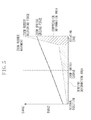
- FIG. 5 is a graph illustrating a state of deformation of a zoom rubber 122 and a zoom spring 123 when the zoom lever 112 is rotated.
- a digital camera 100 which is an example of an electronic apparatus in which the present invention is applied, will be described using FIGS. 1 to 5 .
- FIG. 1 is an exploded perspective diagram illustrating a configuration near a zoom lever of the digital camera 100 .
- a release button 111 is an operation member for performing imaging preparation and for starting imaging by being pressed.
- the release button 111 is attached to a zoom lever 112 .
- a release spring 118 is arranged between the release button 111 and the zoom lever 112 .
- the release spring 118 applies an urging force in a direction in which the zoom lever 112 and the release button 111 are moved apart.
- the release button 111 when the release button 111 is pressed, against the urging force of the release spring 118 , the release button 111 is made to stroke the zoom lever 112 .
- a boss 111 a is formed on the release button 111 . By pressing the release button 111 , this boss 111 a is made to protrude from the zoom lever 112 , whereby a release switch 125 is turned on.
- a top cover 117 is an exterior member arranged on an upper face of the digital camera.
- the top cover 117 functions as a holding member for rotatably holding the zoom lever 112 to which the release button 111 is attached.
- On the top cover 117 are formed a circular opening 117 a , which serves as the rotational center of the zoom lever 112 , and circular arc shape openings 117 b and 117 c formed around the periphery of the circular opening 117 a.
- a cylindrical member 112 a On the zoom lever 112 are formed a cylindrical member 112 a , bosses 112 b and 112 c on which a screw seat is formed, and a positioning pin 112 d .
- the zoom lever 112 is arranged on the top cover 117 so that the cylindrical member 112 a is positioned in the opening 117 a , the boss 112 b is positioned in the opening 117 b , and the boss 112 b and the positioning pin 112 d are positioned in the opening 117 b , respectively.
- the top cover 117 is sandwiched between the zoom lever 112 and the zoom plate 121 , so that the zoom lever 112 is attached to the top cover 117 .
- a positioning hole 121 a and screw holes 121 b and 121 c On the zoom plate 121 are formed a positioning hole 121 a and screw holes 121 b and 121 c .
- the positioning pin 112 d is inserted into the positioning hole 121 a , and the position of the boss 112 b screw seat is aligned with the screw hole 121 b , and the position of the boss 112 c screw seat is aligned with the screw hole 121 c .
- a fastening screw 119 is screwed into the boss 112 c screw seat, and a stepped screw 120 is screwed into the boss 112 c screw seat.
- the zoom plate 121 is fixed to the zoom lever 112 .
- the zoom lever 112 functions as a lever member and the zoom plate 121 functions as a plate member.
- the integrally-formed zoom lever 112 and zoom plate 121 function as an operation member that can be rotated and operated in two directions from the neutral position.
- the rotational range of the zoom lever 112 is from the position where the boss 112 b abuts an edge (a first edge) of the opening 117 b of the top cover 117 to the position where the boss 112 b abuts the other edge (a second edge) of the opening 117 b of the top cover 117 . Therefore, in the present exemplary embodiment, the opening 117 b formed on the top cover 117 functions as a rotation limiting member that limits the rotational range of the operation member.
- a protrusion 117 d that abuts the zoom spring 123 .
- the zoom spring 123 which is a spring member that urges the zoom lever 112 toward the neutral position, is arranged so that its two arms sandwich the spring hook 121 d of the zoom plate 121 and the protrusion 117 d of the top cover 117 .
- the zoom spring 123 is fixed to the top cover 117 by a screw 124 .
- a ground plate 127 is fitted in between the zoom spring 123 and the top cover 117 .
- the ground plate 127 is connected with a ground potential section in the digital camera. Therefore, the zoom spring 123 , the zoom plate 121 , the fastening screw 119 , the stepped screw 120 , and the screw 124 are set to be the ground potential.
- a zoom rubber 122 is arranged as an elastic member so that a fixing member 122 a , which is a first portion formed on one side, is fixed to a boss 117 e formed on the top cover 117 , and a U-shaped member 122 b , which is a second portion formed on the other side, covers the periphery of the stepped screw 120 . Therefore, the U-shaped member 122 b of the zoom rubber 122 has a U shape, and engages with the integrally-formed zoom lever 112 and zoom plate 121 that function as an operation member.
- the zoom lever 112 is rotated, before the boss 112 b abuts an edge (first edge) of the opening 117 b of the top cover 117 , the U-shaped member 122 b covering the periphery of the stepped screw 120 abuts an abutment member 117 f or 117 g of the top cover 117 .
- the abutment member 117 f or 117 g of the top cover 117 functions as an abutment member.
- the release switch 125 and the zoom switch 126 are mounted on a flexible substrate (not illustrated), overlapping the zoom plate 121 .
- FIGS. 2A and 2B illustrate an appearance of the digital camera 100 .
- FIG. 2A is a front view of the digital camera 100
- FIG. 2B is a rear view of the digital camera 100
- FIG. 2C is a right side view of the digital camera 100
- FIG. 2D is a left side view of the digital camera 100
- FIG. 2E is a top view of the digital camera 100
- FIG. 2F is a bottom view of the digital camera 100 .
- a lens barrel 104 forms an imaging optical system.
- a front cover 105 is an exterior member that covers the front face of the digital camera 100 .
- a flash 106 and an autofocus (AF) auxiliary light window 107 are arranged on the front face of the digital camera 100 .
- a rear face cover 101 is an exterior member that covers the body rear face.
- a protection window 102 protects a liquid crystal panel.
- An intermediate member 103 holds the protection window 102 and is fixed to the rear face cover 101 .
- An operating button group 108 is configured from a center button and peripheral buttons, which are used when performing various settings during imaging and image playback.
- a connector cover 109 protects the terminals provided for connection to various external devices.
- the digital camera 100 includes terminals such as an analog video terminal, a power terminal, and a universal serial bus (USB) terminal.
- a strap base 110 has a hole for passing a strap through.
- the user performs imaging preparation and starts imaging by operating the release button 111 .
- the zoom lever 112 By operating the zoom lever 112 , the user optically or electronically changes the magnification of an object image.
- the power button 113 By operating the power button 113 , the user turns the power source of the digital camera 100 on/off.
- a mode dial 114 By operating a mode dial 114 , the user sets an imaging mode.
- the top cover 117 is an exterior member that covers the upper face of the digital camera 100 . As described above, the zoom lever 112 is attached to the top cover 117 .
- a battery cover 115 covers a battery compartment of the digital camera 100 .
- a tripod hole 116 is a hole for fixing the digital camera 100 to a tripod.
- FIG. 3A illustrates a state in which the zoom lever 112 has not been operated, specifically, a state in which the zoom lever 112 is in the neutral position.
- the zoom spring 123 sandwiches the spring hook 121 d of the zoom plate 121 and the protrusion 117 d of the top cover 117 with both of two arms thereof. Further, neither of the abutment members 121 e or 121 f of the zoom plate 121 abut the arm 126 a of the zoom switch 126 .
- the U-shaped member 122 b of the zoom rubber 122 is pulling the stepped screw 120 in the direction of the arrow N in FIG. 3A . Due to this pulling force, the zoom plate 121 is held in the neutral position. More specifically, when the zoom lever 112 is at the neutral position, the U-shaped member 122 b of the zoom rubber 122 is applying a force on the zoom plate 121 in a direction that is approximately orthogonal to the direction in which the zoom lever 112 is operated.
- FIG. 3B illustrates a state in which, from the state illustrated in FIG. 3A , the zoom lever 112 has been rotated in an anticlockwise direction, so that the boss 112 b abuts an edge (first edge) of the opening 117 b of the top cover 117 .
- the zoom spring 123 produces an urging force in the direction that narrows the distance between its two arms. Therefore, as the distance between the two arms widens, the urging force increases. Consequently, the more the rotation amount of the zoom lever 112 increases, the greater the force for returning to the neutral position.
- FIG. 3B illustrates a state in which the urging force is at its greatest.
- FIG. 4A illustrates a state in which, in the state illustrated in FIG. 3B , the zoom switch 126 , the zoom rubber 122 , the zoom spring 123 , the screw 124 , and the zoom plate 121 have been removed.
- the boss 112 b is in a state abutting an edge (first edge) of the opening 117 b of the top cover 117 .
- the boss 112 b is in a state of abutting an edge (first edge) of the opening 117 b of the top cover 117 , prior to that, the U-shaped member 122 b , which is wound around the periphery of the stepped screw 120 , abuts the abutment member 117 f of the top cover 117 . Since the boss 112 b abuts an edge (first edge) of the opening 117 b after the U-shaped member 122 b abuts the abutment member 117 f , the collision of the boss 112 b abutting the edge of the opening 117 b can be mitigated, enabling the collision sound to be reduced.
- the zoom plate 121 when in the state illustrated in FIG. 3B , if operation of the zoom lever 112 is released, due to the urging force of the zoom spring 123 and the restoring force of the zoom rubber 122 , the zoom plate 121 returns to the state illustrated in FIG. 3A . At this stage, the zoom plate 121 vibrates near the neutral position, and then returns to the state illustrated in FIG. 3A . More specifically, due to the urging force of the zoom spring 123 and the restoring force of the zoom rubber 122 , the zoom plate 121 is rotated clockwise to a position beyond the neutral position.
- the zoom plate 121 is rotated anticlockwise.
- the zoom lever 112 returns to the neutral position, the zoom plate 121 vibrates in such a manner near the neutral position.
- the arms of the zoom spring 123 and the spring hook 121 d repeatedly collide, thereby producing a collision sound.
- the vibrations can be quickly made to converge.
- the U-shaped member 122 b of the zoom rubber 122 pulling the stepped screw 120 in the direction of the arrow N in FIG. 3A , the U-shaped member 122 b is functioning as a damper for dampening vibrations.
- FIG. 3C illustrates, from the state illustrated in FIG. 3A , a state in which the zoom lever 112 has been rotated in a clockwise direction, so that the boss 112 b abuts an edge (first edge) of the opening 117 b of the top cover 117 . More specifically, from the state illustrated in FIG. 3A , if the zoom lever 112 is rotated in a clockwise direction, in a state in which one of the arms of the zoom spring 123 is caught by the protrusion 117 d , the other arm of the zoom spring 123 is elastically deformed by the spring hook 121 d.
- the zoom lever 112 As the distance between the two arms of the zoom spring 123 widens, the urging force increases, reaching a maximum in the state illustrated in FIG. 3C . From the state illustrated in FIG. 3A , if the zoom lever 112 is rotated in a clockwise direction, the abutment member 121 e of the zoom plate 121 abuts the arm 126 a of the zoom switch 126 , and pushes the arm 126 a over. Consequently, the zoom switch 126 outputs a signal to reduce the object image.
- FIG. 4B illustrates a state in which, in the state illustrated in FIG. 3C , the zoom switch 126 , the zoom rubber 122 , the zoom spring 123 , the screw 124 , and the zoom plate 121 have been removed.
- the boss 112 b is in a state of abutting an edge (first edge) of the opening 117 b of the top cover 117 .
- the U-shaped member 122 b which is wound around the periphery of the stepped screw 120 , abuts the abutment member 117 g of the top cover 117 , and then the boss 112 b abuts the other edge (second edge) of the opening 117 b of the top cover 117 . Therefore, the collision of the boss 112 b abutting an edge (first edge) of the opening 117 b can be mitigated, enabling the collision sound to be reduced.
- FIG. 5 is a graph illustrating a state of deformation of the zoom rubber 122 and the zoom spring 123 when the zoom lever 112 is rotated.
- the zoom rubber 122 is elastically deformed by a smaller elastic modulus than the zoom spring 123 .
- the zoom switch 126 outputs a signal.
- the zoom lever 112 abuts the abutment member 117 f or 117 g of the top cover 117 , the U-shaped member 122 b of the zoom rubber 122 starts compressive deformation, and is elastically deformed by a larger elastic modulus than the zoom spring 123 .
- the maximum compression amount is reached in the states illustrated in FIG. 3B or 3 C in which rotation is limited.
- the zoom rubber 122 has two areas, a bending deformation area and a compression deformation area. After the zoom switch 126 outputs a signal, the deformation area of the zoom rubber 122 switches from the state illustrated in FIG. 3B or 3 C in which rotation is limited to the previous state.
- a collision sound is mitigated by causing the zoom rubber 122 to compressively deform.
- the vibration sound of the zoom plate 121 is dampened and mitigated by the force for holding the zoom lever 112 in the neutral position of the zoom rubber 122 . Consequently, operation sounds produced during operation of the zoom lever 112 are mitigated, so that unnecessary sounds can be prevented from being recorded when capturing a moving image.
Landscapes
- Engineering & Computer Science (AREA)
- Multimedia (AREA)
- Signal Processing (AREA)
- Studio Devices (AREA)
- Camera Bodies And Camera Details Or Accessories (AREA)
Applications Claiming Priority (2)
| Application Number | Priority Date | Filing Date | Title |
|---|---|---|---|
| JP2010071938A JP2011203585A (ja) | 2010-03-26 | 2010-03-26 | 撮像装置 |
| JP2010-071938 | 2010-03-26 |
Publications (2)
| Publication Number | Publication Date |
|---|---|
| US20110234891A1 US20110234891A1 (en) | 2011-09-29 |
| US8508658B2 true US8508658B2 (en) | 2013-08-13 |
Family
ID=44656040
Family Applications (1)
| Application Number | Title | Priority Date | Filing Date |
|---|---|---|---|
| US13/071,407 Expired - Fee Related US8508658B2 (en) | 2010-03-26 | 2011-03-24 | Electronic apparatus |
Country Status (2)
| Country | Link |
|---|---|
| US (1) | US8508658B2 (enExample) |
| JP (1) | JP2011203585A (enExample) |
Cited By (1)
| Publication number | Priority date | Publication date | Assignee | Title |
|---|---|---|---|---|
| US20120307138A1 (en) * | 2011-06-03 | 2012-12-06 | Canon Kabushiki Kaisha | Electronic apparatus |
Families Citing this family (4)
| Publication number | Priority date | Publication date | Assignee | Title |
|---|---|---|---|---|
| JP2012185351A (ja) * | 2011-03-07 | 2012-09-27 | Sanyo Electric Co Ltd | 操作部を有する電子機器 |
| JP2013066064A (ja) | 2011-09-16 | 2013-04-11 | Sony Corp | 音響再生装置および照明装置ならびに吊り下げ式開閉装置 |
| JP5541430B1 (ja) | 2013-08-19 | 2014-07-09 | ソニー株式会社 | 撮像ユニット、装着装置 |
| JP5541429B1 (ja) * | 2013-08-19 | 2014-07-09 | ソニー株式会社 | 撮像装置 |
Citations (9)
| Publication number | Priority date | Publication date | Assignee | Title |
|---|---|---|---|---|
| US5684640A (en) * | 1994-04-27 | 1997-11-04 | Nikon Corporation | Camera with vibration compensation device having anti-vibration lens urging mechanism and feed screw mechanism |
| US20060056058A1 (en) * | 2004-09-10 | 2006-03-16 | Chong Seng C | Variable focus optic module and optic system |
| US20060209205A1 (en) * | 2005-03-19 | 2006-09-21 | Hon Hai Precision Industry Co., Ltd. | Digital camera module with manual focusing function |
| US7208905B2 (en) * | 2004-10-28 | 2007-04-24 | Konica Minolta Photo Imaging, Inc. | Driving method, driving mechanism, and image capturing apparatus |
| US20070217029A1 (en) * | 2006-03-15 | 2007-09-20 | Fujinon Corporation | Lens device |
| US20080174690A1 (en) * | 2007-01-24 | 2008-07-24 | Hon Hai Precision Industry Co., Ltd. | Lens module with ramped lens and camera module with same |
| JP2008203632A (ja) | 2007-02-21 | 2008-09-04 | Canon Inc | 電子機器 |
| US7782559B2 (en) * | 2008-04-28 | 2010-08-24 | Fu Zhun Precision Industry (Shen Zhen) Co., Lt.d | Camera module |
| US20110007202A1 (en) * | 2009-07-10 | 2011-01-13 | Hon Hai Precision Industry Co., Ltd. | Optical zoom camera module |
-
2010
- 2010-03-26 JP JP2010071938A patent/JP2011203585A/ja not_active Withdrawn
-
2011
- 2011-03-24 US US13/071,407 patent/US8508658B2/en not_active Expired - Fee Related
Patent Citations (10)
| Publication number | Priority date | Publication date | Assignee | Title |
|---|---|---|---|---|
| US5684640A (en) * | 1994-04-27 | 1997-11-04 | Nikon Corporation | Camera with vibration compensation device having anti-vibration lens urging mechanism and feed screw mechanism |
| US20060056058A1 (en) * | 2004-09-10 | 2006-03-16 | Chong Seng C | Variable focus optic module and optic system |
| US7208905B2 (en) * | 2004-10-28 | 2007-04-24 | Konica Minolta Photo Imaging, Inc. | Driving method, driving mechanism, and image capturing apparatus |
| US20060209205A1 (en) * | 2005-03-19 | 2006-09-21 | Hon Hai Precision Industry Co., Ltd. | Digital camera module with manual focusing function |
| US7679670B2 (en) * | 2005-03-19 | 2010-03-16 | Hon Hai Precision Industry Co., Ltd. | Digital camera module with manual focusing function |
| US20070217029A1 (en) * | 2006-03-15 | 2007-09-20 | Fujinon Corporation | Lens device |
| US20080174690A1 (en) * | 2007-01-24 | 2008-07-24 | Hon Hai Precision Industry Co., Ltd. | Lens module with ramped lens and camera module with same |
| JP2008203632A (ja) | 2007-02-21 | 2008-09-04 | Canon Inc | 電子機器 |
| US7782559B2 (en) * | 2008-04-28 | 2010-08-24 | Fu Zhun Precision Industry (Shen Zhen) Co., Lt.d | Camera module |
| US20110007202A1 (en) * | 2009-07-10 | 2011-01-13 | Hon Hai Precision Industry Co., Ltd. | Optical zoom camera module |
Cited By (2)
| Publication number | Priority date | Publication date | Assignee | Title |
|---|---|---|---|---|
| US20120307138A1 (en) * | 2011-06-03 | 2012-12-06 | Canon Kabushiki Kaisha | Electronic apparatus |
| US8743277B2 (en) * | 2011-06-03 | 2014-06-03 | Canon Kabushiki Kaisha | Electronic apparatus |
Also Published As
| Publication number | Publication date |
|---|---|
| JP2011203585A (ja) | 2011-10-13 |
| US20110234891A1 (en) | 2011-09-29 |
Similar Documents
| Publication | Publication Date | Title |
|---|---|---|
| US8743277B2 (en) | Electronic apparatus | |
| US7941045B2 (en) | Camera body, interchangeable lens unit, and imaging apparatus | |
| JP4769908B2 (ja) | 撮像装置 | |
| US8508658B2 (en) | Electronic apparatus | |
| WO2001063333A1 (en) | Lens driver | |
| JP2007163855A (ja) | デジタルカメラ | |
| JP5322959B2 (ja) | バリア装置及び撮影装置 | |
| JP2002290816A (ja) | 固定装置及びそれを用いた手振れ補正可能な撮像装置 | |
| JP2007258198A (ja) | 蓋部材の支持構造及び電子機器 | |
| JP6980576B2 (ja) | 撮像装置 | |
| JP7207967B2 (ja) | 電子装置 | |
| US11184540B2 (en) | Image pickup apparatus with a flexible printed circuit board with a bent portion | |
| JP2019079696A (ja) | 電子機器 | |
| JP3513820B2 (ja) | レンズ位置調整方法 | |
| CN114647130B (zh) | 电子设备 | |
| US20130208177A1 (en) | Electronic apparatus having operation portion | |
| JP3204898B2 (ja) | ズーム操作装置 | |
| JP6833416B2 (ja) | 電子機器 | |
| JP2007257844A (ja) | 押釦構造 | |
| KR20100104049A (ko) | 디지털 영상 처리장치 | |
| JP2018189861A (ja) | 電子機器 | |
| JP2024151447A (ja) | 撮像装置 | |
| JP2015060050A (ja) | 撮像装置のレンズマウント構造 | |
| JP2015144363A (ja) | 電子機器 | |
| JP2014052600A (ja) | 把持部材および撮像装置 |
Legal Events
| Date | Code | Title | Description |
|---|---|---|---|
| AS | Assignment |
Owner name: CANON KABUSHIKI KAISHA, JAPAN Free format text: ASSIGNMENT OF ASSIGNORS INTEREST;ASSIGNOR:KEI, HIDETOSHI;REEL/FRAME:026421/0193 Effective date: 20110309 |
|
| STCF | Information on status: patent grant |
Free format text: PATENTED CASE |
|
| FPAY | Fee payment |
Year of fee payment: 4 |
|
| MAFP | Maintenance fee payment |
Free format text: PAYMENT OF MAINTENANCE FEE, 8TH YEAR, LARGE ENTITY (ORIGINAL EVENT CODE: M1552); ENTITY STATUS OF PATENT OWNER: LARGE ENTITY Year of fee payment: 8 |
|
| FEPP | Fee payment procedure |
Free format text: MAINTENANCE FEE REMINDER MAILED (ORIGINAL EVENT CODE: REM.); ENTITY STATUS OF PATENT OWNER: LARGE ENTITY |
|
| LAPS | Lapse for failure to pay maintenance fees |
Free format text: PATENT EXPIRED FOR FAILURE TO PAY MAINTENANCE FEES (ORIGINAL EVENT CODE: EXP.); ENTITY STATUS OF PATENT OWNER: LARGE ENTITY |
|
| STCH | Information on status: patent discontinuation |
Free format text: PATENT EXPIRED DUE TO NONPAYMENT OF MAINTENANCE FEES UNDER 37 CFR 1.362 |
|
| FP | Lapsed due to failure to pay maintenance fee |
Effective date: 20250813 |