US8480331B2 - Road making machine with a material deflector - Google Patents
Road making machine with a material deflector Download PDFInfo
- Publication number
- US8480331B2 US8480331B2 US13/359,839 US201213359839A US8480331B2 US 8480331 B2 US8480331 B2 US 8480331B2 US 201213359839 A US201213359839 A US 201213359839A US 8480331 B2 US8480331 B2 US 8480331B2
- Authority
- US
- United States
- Prior art keywords
- making machine
- material deflector
- road making
- operating mode
- road
- Prior art date
- Legal status (The legal status is an assumption and is not a legal conclusion. Google has not performed a legal analysis and makes no representation as to the accuracy of the status listed.)
- Active
Links
Images


Classifications
-
- E—FIXED CONSTRUCTIONS
- E01—CONSTRUCTION OF ROADS, RAILWAYS, OR BRIDGES
- E01C—CONSTRUCTION OF, OR SURFACES FOR, ROADS, SPORTS GROUNDS, OR THE LIKE; MACHINES OR AUXILIARY TOOLS FOR CONSTRUCTION OR REPAIR
- E01C19/00—Machines, tools or auxiliary devices for preparing or distributing paving materials, for working the placed materials, or for forming, consolidating, or finishing the paving
- E01C19/48—Machines, tools or auxiliary devices for preparing or distributing paving materials, for working the placed materials, or for forming, consolidating, or finishing the paving for laying-down the materials and consolidating them, or finishing the surface, e.g. slip forms therefor, forming kerbs or gutters in a continuous operation in situ
-
- B—PERFORMING OPERATIONS; TRANSPORTING
- B60—VEHICLES IN GENERAL
- B60R—VEHICLES, VEHICLE FITTINGS, OR VEHICLE PARTS, NOT OTHERWISE PROVIDED FOR
- B60R19/00—Wheel guards; Radiator guards, e.g. grilles; Obstruction removers; Fittings damping bouncing force in collisions
- B60R19/54—Obstruction removers or deflectors
-
- E—FIXED CONSTRUCTIONS
- E01—CONSTRUCTION OF ROADS, RAILWAYS, OR BRIDGES
- E01B—PERMANENT WAY; PERMANENT-WAY TOOLS; MACHINES FOR MAKING RAILWAYS OF ALL KINDS
- E01B27/00—Placing, renewing, working, cleaning, or taking-up the ballast, with or without concurrent work on the track; Devices therefor; Packing sleepers
Definitions
- the invention relates to a road making machine with a running gear and at least one material deflector in front of the running gear in the driving direction and which can be pivoted up and lowered, and including a control system that enables an operator can to select between at least the laying and transport operating modes and to a method of operating such a road making machine.
- the material deflector must be temporarily folded up to be able, for example, to drive over obstacles, such as manhole covers.
- the accessibility of the material deflector is sometimes very bad as the walls of the material bunker of the road making machine which are situated immediately above the material deflector might be folded down.
- a material deflector for a road making machine which is described in DE 299 15 875 U1 and in the parallel EP 1 083 263 A1, respectively, offers an improvement.
- This document already identifies the problem that material scrapers can disturb during the loading of a road finishing machine onto a low bed truck, or that they can leave undesired traces in the road surface at obstacles. Therefore, DE 299 15 875 U1 suggests to retain the material deflector such that it is only limited in its travel downwards, that means that it has free travel to the top.
- a road making machine having the features of claim a running gear and at least one material deflector in front of the running gear in the driving direction and which can be pivoted up and lowered, and including a control system that enables an operator to select between at least the laying and transport operating modes and by a method of operating a road making machine having the features of claim 10 , respectively.
- the road making machine comprises a control system by means of which an operator can choose between different operating modes, including at least the laying and transport operating modes.
- the road making machine In the operating mode laying, the road making machine is adapted to contribute to the laying of a road surface.
- the road making machine In the transport operating mode, the road making machine can be moved from one point to another without any laying operation taking place simultaneously.
- control system in the road making machine is now adapted to automatically completely pivot up the material deflector in the transport operating mode.
- the control system is adapted to let the operator manually adjust a pivot position of the material deflector.
- the advantage of the road making machine according to the invention is that the operator almost does not have to take care of the material deflector anymore. It is sufficient for the operator to choose between the laying and transport. operating modes The control system will then automatically take care of the optimal orientation of the material deflector without the operator having to separately actuate, not to speak of manually fold up, the material deflector. In this manner, the handling of the material deflector is substantially improved, and damages to the road making machine or to other transport vehicles, such as low bed trucks, can be avoided. For in the road making machine according to the invention, it can no longer happen that an operator of this road making machine forgets to bring the material deflector into its folded up position during a transport drive or during the loading of the road making machine.
- a pivot position to be assumed by the material deflector in the laying operating mode (which is optionally variable) being stored in the control system. If the operator selects or activates the operating mode laying, the material deflector is automatically brought into this stored pivot position. From this position, it can be further pivoted manually. The operator can store a new standard pivot position in the control system for the operating mode laying.
- the material deflector can be pivoted up with respect to the horizontal by an angle of up to 30°, preferably up to 35°. This permits both an advantageous loading angle of the road making machine, for example onto a low bed truck, and a safe removal of the material deflector in case of obstacles in front of the road making machine.
- the automatic adjustment of the material deflector into its different pivot positions can be realized by means of a hydraulic system.
- hydraulic circuits are anyway already provided on road making machines, for example for adjusting material bunker walls or screeds, so that the provision of another hydraulic system for the material deflector does not involve any substantial additional efforts. It would also be conceivable to integrate the hydraulic system for the material deflector into an already existing hydraulic system.
- a point of application of a hydraulic cylinder at the material deflector is preferably retained in an oblong hole.
- the arrangement of such an oblong hole directly at the point of application of the hydraulic cylinder permits free travel for the material deflector in a constructively simple manner.
- a hydraulic cylinder that pivots the material deflector to assume a floating position to retain the material deflector with free travel.
- the floating position of the hydraulic cylinder could even be adjustable to adjust the angle over which the material deflector can adjust with free travel.
- the material deflector In the position where it is completely pivoted up, the material deflector should be secured so that it cannot be unintentionally pivoted downwards. This can be done by retaining the material deflector with a check valve located in the hydraulic system, by a latch and/or by a mechanical toggle when the deflector s completely pivoted up.
- the road making machine can include a special operational control, for example a key button.
- a special operational control for example a key button.
- the control system automatically causes the material deflector to pivot up into its completely raised position.
- This special operational control can be actuated by the operator of the road making machine when he identifies an obstacle or any other situation requiring the operator to quickly or temporarily pivot the material deflector into the up position.
- the road making machine can be in particular a road finishing machine, a feeder for a road finishing machine, or an excavator.
- a road finishing machine a feeder for a road finishing machine
- an excavator a road finishing machine
- other construction machines for example track-laying machines, could comprise a material deflector and be configured according to the invention.
- the invention also relates to a method for the operation of a road making machine wherein an operator chooses, by means of a control system of the road making machine, at least between the operating modes, wherein the material deflector is automatically pivoted up to its highest pivot position in the transport operating mode, and wherein the operator manually adjusts a pivot position of the material deflector in the laying operating mode.
- FIG. 1 shows a road making machine according to the invention, in particular a road finishing machine
- FIG. 2 shows the material deflector of a road making machine according to the invention in a lower pivot position
- FIG. 3 shows the material deflector shown in FIG. 2 in its completely raised position
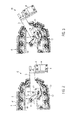
- FIG. 4 shows a second embodiment of a material deflector according to the invention.
- FIG. 5 shows the material deflector shown in FIG. 4 in its completely raised position.
- FIG. 1 shows a road finishing machine F as an example of a road making machine according to the invention.
- the road making machine F can alternatively be an excavator or a feeder.
- This road finishing machine F has a chassis 1 with a running gear R, in the shown case a tracklaying gear.
- a material bunker B for laying material is provided which is filled from a filling side E.
- On the chassis 1 there is a primary drive source 2 , for example a diesel engine, and behind this drive source 2 , there is a driver stand 3 .
- the tracklaying gear R comprises a longitudinally placed support T which can be supported at the chassis 1 to be movable vertically or in a swinging manner.
- the support T carries a caterpillar track K on chain wheels.
- a material deflector M is arranged in front of its caterpillar track K in the working drive direction.
- the material deflector M serves to displace material lying on the foundation course in front of the road finishing machine F and in particular to keep it away from the running gear R.
- the material deflector can have a deflecting surface A inclined with respect to the working drive direction by means of which it displaces the material lying on the foundation course to the inside between the caterpillar tracks K to thus keep the track of the caterpillar tracks K clear.
- the road making machine F comprises a control system S.
- an operator of the road making machine F can choose between various operating modes, in particular between the operating modes transport and laying.
- the operator will choose the laying operating mode when the road making machine is to actively take part in a road making process, for example by applying the road surface onto the foundation course or by transporting laying material to a following road finishing machine.
- the control system S is preferably adapted to put certain working units, such as transport devices, conveyor devices or a screed, into an active operating state, when the laying operating mode was chosen.
- the operator will in contrast choose the operating mode transport when the road making machine F is only to be displaced without a road surface being laid.
- the road finishing machine F according to FIG. 1 moreover has a hydraulic system H.
- This schematically represented hydraulic system H is controlled by the control system S.
- the hydraulic system is used, among other things, to pivot the material deflector M.
- FIG. 2 shows a side view of a material deflector M according to the invention which is located in front of the running gear R of a road making machine F and mounted on chassis 1 .
- the material deflector M is arranged such that its deflecting surface A is located in the working drive direction in front of the front end of the running gear R of the road making machine F.
- the running gear R does not have to be a tracklaying gear, it can just as well be a wheel gear.
- the deflecting surface A is inclined with respect to the working drive direction of the running gear R. Via fastening means 4 , for example screws, the deflecting surface A is releasably and optionally adjustably fixed to a boom 5 .
- This boom can be pivoted about a horizontal swiveling axis 6 .
- This swiveling axis 6 is located at the support T of the running gear R.
- a hydraulic cylinder 7 is provided between the support T of the running gear R and the boom 5 .
- the hydraulic cylinder 7 can be supplied with pressurized fluid via the hydraulic system H to retract or extend a piston 8 and thus change the length of the hydraulic cylinder 7 .
- the left end of the hydraulic cylinder in FIG. 2 is fixed to a support element 9 , which in turn is fixed to the support T of the running gear R via a swivel bearing 10 so as to be pivoting.
- the outer end of the piston 8 opposed to the support element 9 represents the point of application 11 of the hydraulic cylinder 7 .
- This point of application 11 which can comprise, for example, a pin arranged in the horizontal direction, is arranged in an oblong hole 12 in the boom 5 .
- FIG. 2 shows the material deflector M in a lowered position in which the boom 5 extends in an approximately horizontal direction, i.e. the material deflector (or scraper) M rests on the foundation course or at a stop screw.
- the hydraulic cylinder 7 is in its retracted position.
- the point of application 11 of the hydraulic cylinder 7 is located in the center of the oblong hole 12 in the boom 5 .
- the interaction between the oblong hole 12 and the point of application 11 of the hydraulic cylinder 7 permits free upward and downward travel for the material deflector M.
- the material deflector M can pivot downwards about a pivot angle until the point of application 11 of the hydraulic cylinder 7 reaches the right end 13 of the oblong hole 12 or a stop screw, or it can pivot upwards until the point of application 11 of the hydraulic cylinder 7 reaches the left end 14 of the oblong hole 12 .
- the material deflector M can perform such a passive temporary pivoting movement when encountering an obstacle in front of the road making machine F. Free travel can also be permitted by the hydraulic cylinder 7 taking a floating position.
- FIG. 3 shows the material deflector M in its completely raised position.
- the material deflector has been pivoted upwards about an angle ⁇ of about 27° by the hydraulic system H having supplied the hydraulic cylinder 7 with high-pressure fluid and thus extended the hydraulic cylinder 7 .
- the point of application 11 of the hydraulic cylinder 7 acts on the front end 13 of the oblong hole 12 and thus moves the boom 5 upward.
- This movement can be caused by the control system H by the operator choosing the operating mode transport on the operator panel D.
- the movement can also be triggered by an operator on the driver stand 3 of the road making machine F actuating a special operational control 15 , for example a push button 15 , to temporarily lift the material deflector M during the operating mode laying and without changing this operating mode.
- the operation of the road making machine F according to the invention is substantially facilitated in that the movement of the material deflector M is automatically effected by the operator choosing a certain operating mode of the road making machine F and/or actuating a special operational control 15 .
- the cumbersome manual folding up of the material deflector M can be avoided.
- FIG. 4 shows a second embodiment of a material deflector M.
- This second embodiment differs from the first embodiment in that a stop screw 20 is provided at the support T of the running gear R of the road finishing machine F.
- This stop screw 20 can be even more clearly seen in the completely raised position of the material deflector M which is shown in FIG. 5 .
- the stop screw 20 cooperates with a corresponding counterstop at the boom 5 of the material deflector M and limits the pivoting travel of the boom 5 to the rear.
- the stop screw 20 can be optionally adjusted to change the pivot angle of the boom 5 of the material deflector M which can be covered to the rear.
- the material deflector M does not have free travel to the top and bottom, but that it only has free travel to the top (or to the bottom) to be able to evade obstacles.
Landscapes
- Engineering & Computer Science (AREA)
- Architecture (AREA)
- Civil Engineering (AREA)
- Structural Engineering (AREA)
- Mechanical Engineering (AREA)
- Road Paving Machines (AREA)
Applications Claiming Priority (2)
| Application Number | Priority Date | Filing Date | Title |
|---|---|---|---|
| DE11001515.3 | 2011-02-23 | ||
| EP11001515.3A EP2492396B1 (de) | 2011-02-23 | 2011-02-23 | Straßenbaumaschine mit einem Materialabweiser |
Publications (2)
| Publication Number | Publication Date |
|---|---|
| US20120213585A1 US20120213585A1 (en) | 2012-08-23 |
| US8480331B2 true US8480331B2 (en) | 2013-07-09 |
Family
ID=44117026
Family Applications (1)
| Application Number | Title | Priority Date | Filing Date |
|---|---|---|---|
| US13/359,839 Active US8480331B2 (en) | 2011-02-23 | 2012-01-27 | Road making machine with a material deflector |
Country Status (5)
| Country | Link |
|---|---|
| US (1) | US8480331B2 (pl) |
| EP (1) | EP2492396B1 (pl) |
| JP (1) | JP5960443B2 (pl) |
| CN (1) | CN102650115B (pl) |
| PL (1) | PL2492396T3 (pl) |
Cited By (5)
| Publication number | Priority date | Publication date | Assignee | Title |
|---|---|---|---|---|
| CN105317058B (zh) * | 2014-07-28 | 2018-09-04 | 郭立友 | 遥控打隧道挖河疏浚机 |
| US10428471B1 (en) | 2018-05-22 | 2019-10-01 | Caterpillar Paving Products Inc. | Systems and methods for controlling cold planer material flow |
| US10472777B1 (en) * | 2018-05-02 | 2019-11-12 | Caterpillar Paving Products Inc. | Screed tow point assembly for paver |
| US10640931B2 (en) | 2017-12-13 | 2020-05-05 | Joseph Voegele Ag | Road finisher with liftable chassis |
| US10745867B2 (en) | 2016-01-12 | 2020-08-18 | Joseph Voegele Ag | Paving machine with projector as navigation aid |
Families Citing this family (6)
| Publication number | Priority date | Publication date | Assignee | Title |
|---|---|---|---|---|
| DE202012003217U1 (de) * | 2012-03-29 | 2013-07-01 | Joseph Vögele AG | Außensteuerstand für eine Baumaschine |
| JP6124714B2 (ja) * | 2013-07-08 | 2017-05-10 | 住友建機株式会社 | 舗装機械の合材除去装置 |
| DE202014007084U1 (de) * | 2014-08-29 | 2015-12-04 | Joseph Vögele AG | Baumaschine mit versetzten Bunkerrückwänden |
| PL3091125T3 (pl) * | 2015-05-06 | 2017-12-29 | Joseph Vögele AG | Maszyna budowlana z urządzeniem podnoszącym dla procesu załadowczego i sposób przestawiania tylnej klapy |
| DE102016010474A1 (de) | 2015-09-07 | 2017-03-09 | Dynapac Gmbh | Straßenbaumaschine, insbesondere Straßenfertiger oder Beschicker |
| JP6954751B2 (ja) * | 2017-03-13 | 2021-10-27 | 世紀東急工業株式会社 | アスファルトフィニッシャ |
Citations (7)
| Publication number | Priority date | Publication date | Assignee | Title |
|---|---|---|---|---|
| US2080888A (en) * | 1936-04-21 | 1937-05-18 | Fred W Hintz | Ridge breaker |
| US2623310A (en) * | 1946-06-19 | 1952-12-30 | Case Co J I | Wheel track attachment for tractors |
| US3732024A (en) * | 1971-03-01 | 1973-05-08 | J Gendrich | Leveler for paving machine |
| US4026658A (en) | 1974-07-26 | 1977-05-31 | Barber-Greene Company | Automatic support system for a screed |
| US5000650A (en) | 1989-05-12 | 1991-03-19 | J.I. Case Company | Automatic return to travel |
| US5974773A (en) * | 1996-11-05 | 1999-11-02 | Rieck; Ryan William | Crop divider for the wheel of an agricultural machine |
| DE29915875U1 (de) | 1999-09-09 | 1999-12-30 | Joseph Voegele Ag, 68163 Mannheim | Straßenfertiger |
Family Cites Families (5)
| Publication number | Priority date | Publication date | Assignee | Title |
|---|---|---|---|---|
| JPH0713363B2 (ja) * | 1991-03-27 | 1995-02-15 | 建設省北陸地方建設局長 | 操作ボード式のブレード切換装置 |
| JPH0742191A (ja) * | 1993-07-29 | 1995-02-10 | Yasunori Nara | 暗渠排水工事用穿孔装置付き掘削機 |
| JPH0713574U (ja) * | 1993-08-04 | 1995-03-07 | 實 亀岡 | 排土板付き装軌運搬車 |
| JP2005256478A (ja) * | 2004-03-12 | 2005-09-22 | Hitachi Constr Mach Co Ltd | 転圧機械 |
| EP2886718B1 (de) * | 2010-06-11 | 2016-05-25 | Joseph Vögele AG | Bohlenanordnung für einen straßenfertiger |
-
2011
- 2011-02-23 PL PL11001515T patent/PL2492396T3/pl unknown
- 2011-02-23 EP EP11001515.3A patent/EP2492396B1/de active Active
-
2012
- 2012-01-27 US US13/359,839 patent/US8480331B2/en active Active
- 2012-02-22 JP JP2012035746A patent/JP5960443B2/ja active Active
- 2012-02-22 CN CN201210042940.8A patent/CN102650115B/zh active Active
Patent Citations (8)
| Publication number | Priority date | Publication date | Assignee | Title |
|---|---|---|---|---|
| US2080888A (en) * | 1936-04-21 | 1937-05-18 | Fred W Hintz | Ridge breaker |
| US2623310A (en) * | 1946-06-19 | 1952-12-30 | Case Co J I | Wheel track attachment for tractors |
| US3732024A (en) * | 1971-03-01 | 1973-05-08 | J Gendrich | Leveler for paving machine |
| US4026658A (en) | 1974-07-26 | 1977-05-31 | Barber-Greene Company | Automatic support system for a screed |
| US5000650A (en) | 1989-05-12 | 1991-03-19 | J.I. Case Company | Automatic return to travel |
| US5974773A (en) * | 1996-11-05 | 1999-11-02 | Rieck; Ryan William | Crop divider for the wheel of an agricultural machine |
| DE29915875U1 (de) | 1999-09-09 | 1999-12-30 | Joseph Voegele Ag, 68163 Mannheim | Straßenfertiger |
| EP1083263A1 (de) | 1999-09-09 | 2001-03-14 | Joseph Vögele AG | Strassenfertiger |
Non-Patent Citations (1)
| Title |
|---|
| European Search Report dated Aug. 2, 2011, which issued in corresponding EP Application No. 11001515.3. |
Cited By (5)
| Publication number | Priority date | Publication date | Assignee | Title |
|---|---|---|---|---|
| CN105317058B (zh) * | 2014-07-28 | 2018-09-04 | 郭立友 | 遥控打隧道挖河疏浚机 |
| US10745867B2 (en) | 2016-01-12 | 2020-08-18 | Joseph Voegele Ag | Paving machine with projector as navigation aid |
| US10640931B2 (en) | 2017-12-13 | 2020-05-05 | Joseph Voegele Ag | Road finisher with liftable chassis |
| US10472777B1 (en) * | 2018-05-02 | 2019-11-12 | Caterpillar Paving Products Inc. | Screed tow point assembly for paver |
| US10428471B1 (en) | 2018-05-22 | 2019-10-01 | Caterpillar Paving Products Inc. | Systems and methods for controlling cold planer material flow |
Also Published As
| Publication number | Publication date |
|---|---|
| JP2012172515A (ja) | 2012-09-10 |
| JP5960443B2 (ja) | 2016-08-02 |
| CN102650115A (zh) | 2012-08-29 |
| US20120213585A1 (en) | 2012-08-23 |
| EP2492396B1 (de) | 2015-04-08 |
| PL2492396T3 (pl) | 2015-09-30 |
| CN102650115B (zh) | 2016-01-20 |
| EP2492396A1 (de) | 2012-08-29 |
Similar Documents
| Publication | Publication Date | Title |
|---|---|---|
| US8480331B2 (en) | Road making machine with a material deflector | |
| US8770386B2 (en) | Folding transport conveyor for a construction machine, automotive construction machine, as well as method for pivoting a transport conveyor | |
| US10131387B2 (en) | Construction vehicle having a tippable chassis | |
| US20150367901A1 (en) | Vehicle | |
| US9260825B2 (en) | Road-building machine | |
| CA2862668C (en) | Sod positioning machine | |
| EP3237253B1 (en) | Material transfer vehicle having an expandable truck-receiving hopper | |
| US20120284989A1 (en) | Positioning Arrangement For Fitting An Interchangeable Milling Assembly Of A Road-Building Machine | |
| JP6159442B2 (ja) | 供給工程のためのリフト装置を有する建設機械 | |
| CN106894322A (zh) | 铣刨单元的运输装置、运输车辆以及运输铣刨单元的方法 | |
| EA019297B1 (ru) | Вагон-накопитель для транспортировки сыпучего груза и способ | |
| CA2969907C (en) | Positioning assembly for placing steerable drive in multiple positions with respect to milling machine housing | |
| EP3865625A2 (en) | Strike off assembly for a placer spreader | |
| JP5408901B2 (ja) | 荷役車両 | |
| JP2018043577A (ja) | 作業車両のアウトリガジャッキ動作制御装置 | |
| US5405215A (en) | Paving apparatus | |
| US20210163066A1 (en) | Drilling rig | |
| AU2016250434B2 (en) | A vehicle having a ramp arrangement and a ramp arrangement | |
| AU2018200408B2 (en) | Gravel spreader for repairing or building a roadway | |
| EP0624690B1 (en) | Machine for grading road surfaces | |
| EP1512568A1 (en) | Improvements in and relating to a covering system | |
| JP2019137541A (ja) | 高所作業車の安全装置 | |
| JP2023085771A (ja) | 区画線用施工ユニット | |
| WO2025217669A1 (en) | Skid steer attachment | |
| JP2022174405A (ja) | 軌陸車用載退線装置 |
Legal Events
| Date | Code | Title | Description |
|---|---|---|---|
| AS | Assignment |
Owner name: JOSEPH VOGELE AG, GERMANY Free format text: ASSIGNMENT OF ASSIGNORS INTEREST;ASSIGNORS:SCHMIDT, THOMAS;SEIBEL, MARTIN;REEL/FRAME:027852/0828 Effective date: 20120220 |
|
| FEPP | Fee payment procedure |
Free format text: PAYOR NUMBER ASSIGNED (ORIGINAL EVENT CODE: ASPN); ENTITY STATUS OF PATENT OWNER: LARGE ENTITY |
|
| STCF | Information on status: patent grant |
Free format text: PATENTED CASE |
|
| FPAY | Fee payment |
Year of fee payment: 4 |
|
| MAFP | Maintenance fee payment |
Free format text: PAYMENT OF MAINTENANCE FEE, 8TH YEAR, LARGE ENTITY (ORIGINAL EVENT CODE: M1552); ENTITY STATUS OF PATENT OWNER: LARGE ENTITY Year of fee payment: 8 |
|
| MAFP | Maintenance fee payment |
Free format text: PAYMENT OF MAINTENANCE FEE, 12TH YEAR, LARGE ENTITY (ORIGINAL EVENT CODE: M1553); ENTITY STATUS OF PATENT OWNER: LARGE ENTITY Year of fee payment: 12 |