EP0624690B1 - Machine for grading road surfaces - Google Patents
Machine for grading road surfaces Download PDFInfo
- Publication number
- EP0624690B1 EP0624690B1 EP94107481A EP94107481A EP0624690B1 EP 0624690 B1 EP0624690 B1 EP 0624690B1 EP 94107481 A EP94107481 A EP 94107481A EP 94107481 A EP94107481 A EP 94107481A EP 0624690 B1 EP0624690 B1 EP 0624690B1
- Authority
- EP
- European Patent Office
- Prior art keywords
- machine
- hopper
- road surfaces
- grading
- grader blade
- Prior art date
- Legal status (The legal status is an assumption and is not a legal conclusion. Google has not performed a legal analysis and makes no representation as to the accuracy of the status listed.)
- Expired - Lifetime
Links
- 239000000463 material Substances 0.000 claims description 14
- 239000010426 asphalt Substances 0.000 description 12
- 238000004140 cleaning Methods 0.000 description 2
- 230000000694 effects Effects 0.000 description 2
- 238000010276 construction Methods 0.000 description 1
- 230000000670 limiting effect Effects 0.000 description 1
Images


Classifications
-
- E—FIXED CONSTRUCTIONS
- E01—CONSTRUCTION OF ROADS, RAILWAYS, OR BRIDGES
- E01C—CONSTRUCTION OF, OR SURFACES FOR, ROADS, SPORTS GROUNDS, OR THE LIKE; MACHINES OR AUXILIARY TOOLS FOR CONSTRUCTION OR REPAIR
- E01C19/00—Machines, tools or auxiliary devices for preparing or distributing paving materials, for working the placed materials, or for forming, consolidating, or finishing the paving
- E01C19/48—Machines, tools or auxiliary devices for preparing or distributing paving materials, for working the placed materials, or for forming, consolidating, or finishing the paving for laying-down the materials and consolidating them, or finishing the surface, e.g. slip forms therefor, forming kerbs or gutters in a continuous operation in situ
-
- E—FIXED CONSTRUCTIONS
- E01—CONSTRUCTION OF ROADS, RAILWAYS, OR BRIDGES
- E01C—CONSTRUCTION OF, OR SURFACES FOR, ROADS, SPORTS GROUNDS, OR THE LIKE; MACHINES OR AUXILIARY TOOLS FOR CONSTRUCTION OR REPAIR
- E01C2301/00—Machine characteristics, parts or accessories not otherwise provided for
- E01C2301/40—Working platform or walkway
Definitions
- the present invention concerns machines for grading road surfaces (see e.g. DE-A-3237718).
- the aim of the present invention is to provide a machine to lay asphalt, especially on sidewalks or in any case on road sections of limited width, almost fully eliminating the use of manual work but nonetheless providing a finished road surface of extremely commendable characteristics and with a significant reduction in construction costs.
- the grader according to the invention enters this field with innovative technical solutions that make it unique in its kind.
- the machine according to the invention comprises a hopper 1 (figure 1) which is connected to the tracked truck 2 by means of a fifth wheel 3 that allows the hopper to rotate about its vertical axis.
- Levers 4 extend from the tracked truck 2 and support, by means of a so-called parallelogram-like system, the grader blade 5 on which the control post 6 is mounted; the operator that controls the machine climbs onto said control post.
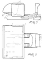
- the screw feeder 7 is arranged inside the guiding hopper 1 (figure 4) and, by rotating in both directions, moves the material deposited by the hopper in order to make it descend through the outlet 8.
- the hopper can be loaded by means of a conventional power loader or with a dumper truck.
- the tow hook 9 allows the machine to be towed with a tractor or a similar towing vehicle.
- the front wall 10 (figures 5 and 6) of the hopper 1 can swing down completely by virtue of the presence of the jacks 11 that move it, thus facilitating the loading of said hopper by means of a truck of any size.
- the shape given to the hopper 1 allows the engine and component parts to be accommodated on the side that lies opposite to the opening in the wall 10.
- grader blade 5 (figures 7 and 8) is connected to the truck that supports the hopper 1 by means of the levers 4, which form a so-called "parallelogram" system.
- the machine according to the invention allows the asphalt to be laid in various ways depending on the particular requirements.
- grader blade 5 is mounted on preferably chromium-plated rods 12 arranged in an inclined position with respect to the advancement axis of the machine, thus allowing the material to be distributed uniformly and any obstacles on the roadbed to be passed over more easily.
- Figure 12 illustrates the laying of asphalt along a strip 13 which is arranged symmetrically along the advancement axis of the machine, and figure 13 illustrates the laying of asphalt on a strip 14 which lies entirely outside the advancement axis of the machine, with the hopper 1 orientated so that its axis is approximately at 45° with respect to the machine advancement axis; figure 14 illustrates the laying of asphalt on a strip 15 which lies partially outside and partially inside the machine, with the hopper 1 orientated at an angle of less than 45° with respect to the axis of the machine.
- the post 6, together with the associated control panel, remains in a central position with respect to the advancement tracks of the truck that supports the machine.
- said screw feeders When said screw feeders are present, they are mounted in the rear part of the machine, between the tractor and the grader blade, and this makes it absolutely impossible to discharge the material in a single position, and therefore the material must be first discharged and then conveyed by the screw feeders, which distribute it and leave traces of asphalt even where they are not necessary, thus requiring an additional and expensive road-cleaning operation.
- the front opening of the side wall 10 allows the hopper 1 to be loaded without entailing losses onto the ground; this is not at all ensured by currently used loading hoppers, which have openings on their side walls to allow this loading.
- the position of the operator is such that he is ensured of great visibility in any working condition, both onto the loading hopper and onto the strip of ground to be covered with asphalt.
- said machine allows substantially perfect and uniform laying of the asphalt along the required strip without needing subsequent manual laying operations or cleaning operations, with a significant reduction in the onerous labor costs and a considerable improvement in the laying characteristics of the material.
Description
Claims (7)
- Machine for grading road surfaces, characterized in that it comprises a loading hopper (1) which is mounted on a tracked device (2) with the interposition of a central wheel (3), rods (4) being arranged at the tracked device (2) so as to form a parallelogram-like system, said rods (4) supporting a post (6) with a platform for an operator and with control panels, a grader blade (5) being mounted below said post (6), the movement of the grader blade (5) being independent of the position of the hopper (1), the material whereof can be discharged along a central or lateral strip as desired by the operator.
- Machine for grading road surfaces according to claim 1, characterized in that a screw feeder (7) with a discharge opening (8) is arranged inside the hopper (1) to move the material inside the hopper (1) and to allow its discharge in the desired position without losses of material.
- Machine for grading road surfaces according to claims 1 and 2, characterized in that the hopper (1) can be opened by swinging down a side wall (10), thus allowing trucks or buckets to load said hopper (1) without unwanted losses of material.
- Machine for grading road surfaces according to claims 1 and 3, characterized in that said rods (4) keep the platform on which the operator rests always horizontal in any condition, even if the terrain over which the machine advances is uneven.
- Machine for grading road surfaces according to claim 3, characterized in that said side wall (10) of the hopper (1) can swing down by means of a piston-operated actuation system (11).
- Machine for grading road surfaces, according to claims 1 to 5, characterized in that said grader blade (5) can move laterally and lay the material inside or outside the advancement path of the tracked device (2) according to particular requirements.
- Machine for grading road surfaces according to claims 1 to 6, characterized in that said grader blade (5) is mounted on rods (12) which are inclined with respect to the advancement axis of the machine.
Applications Claiming Priority (2)
| Application Number | Priority Date | Filing Date | Title |
|---|---|---|---|
| ITVI930079A IT1270778B (en) | 1993-05-13 | 1993-05-13 | ROAD COATS SHAVING MACHINE |
| ITVI930079 | 1993-05-13 |
Publications (3)
| Publication Number | Publication Date |
|---|---|
| EP0624690A2 EP0624690A2 (en) | 1994-11-17 |
| EP0624690A3 EP0624690A3 (en) | 1995-01-04 |
| EP0624690B1 true EP0624690B1 (en) | 1998-07-29 |
Family
ID=11425224
Family Applications (1)
| Application Number | Title | Priority Date | Filing Date |
|---|---|---|---|
| EP94107481A Expired - Lifetime EP0624690B1 (en) | 1993-05-13 | 1994-05-13 | Machine for grading road surfaces |
Country Status (3)
| Country | Link |
|---|---|
| EP (1) | EP0624690B1 (en) |
| DE (1) | DE69411993T2 (en) |
| IT (1) | IT1270778B (en) |
Families Citing this family (2)
| Publication number | Priority date | Publication date | Assignee | Title |
|---|---|---|---|---|
| GB2329168B (en) * | 1997-04-16 | 2001-05-16 | Douglas Patrick J | Tractor unit and wheeled trailer combination |
| GB9707655D0 (en) * | 1997-04-16 | 1997-06-04 | Douglas Patrick J | Tractor unit mobile screening plant combination |
Family Cites Families (3)
| Publication number | Priority date | Publication date | Assignee | Title |
|---|---|---|---|---|
| GB942349A (en) * | 1961-09-01 | 1963-11-20 | Renner Co | Improvements in or relating to curb forming machines |
| DE3237718A1 (en) * | 1982-10-12 | 1983-04-07 | Josef Oevermann Gmbh & Co Hoch | Conversion unit for road finishers for the lateral discharge of material |
| FR2619133B1 (en) * | 1987-08-06 | 1991-05-24 | Gerland | PROCESS FOR PRODUCING HOUSEHOLD CHANNELS AT THE EDGE OF ROAD TRAFFIC LIGHTS MADE OF BITUMINOUS COATED MATERIALS AND DEVICE FOR IMPLEMENTING SAME |
-
1993
- 1993-05-13 IT ITVI930079A patent/IT1270778B/en active IP Right Grant
-
1994
- 1994-05-13 EP EP94107481A patent/EP0624690B1/en not_active Expired - Lifetime
- 1994-05-13 DE DE69411993T patent/DE69411993T2/en not_active Expired - Fee Related
Also Published As
| Publication number | Publication date |
|---|---|
| DE69411993T2 (en) | 1998-12-10 |
| DE69411993D1 (en) | 1998-09-03 |
| EP0624690A2 (en) | 1994-11-17 |
| IT1270778B (en) | 1997-05-07 |
| EP0624690A3 (en) | 1995-01-04 |
| ITVI930079A0 (en) | 1993-05-13 |
| ITVI930079A1 (en) | 1994-11-13 |
Similar Documents
| Publication | Publication Date | Title |
|---|---|---|
| US8205359B2 (en) | Sidewalk grader apparatus and method | |
| US5344254A (en) | Pivoting screed edger | |
| US3130654A (en) | Material distributing and leveling machine | |
| EP0957204B1 (en) | Roadpaver and hopper | |
| US4502389A (en) | Track work train | |
| US5846022A (en) | Apparatus for laying pavement layers | |
| EP1516962B2 (en) | A method of deploying multi-use road paving equipment | |
| JPH0197703A (en) | Method and apparatus for paving asphalt aggregate | |
| US8480331B2 (en) | Road making machine with a material deflector | |
| US20240076838A1 (en) | Aggregate spreading device with spreader system | |
| US3620458A (en) | Dual-purpose vehicle | |
| US4074802A (en) | Concrete receiver and placer for road paving | |
| US3010727A (en) | Dump truck with conveyor and spreader | |
| US5190432A (en) | Dump truck stone slinger | |
| US2950660A (en) | Road surfacing material spreader | |
| US3625489A (en) | Road repair machine | |
| US20190039497A1 (en) | Material dispersal blade for a bottom dump trailer | |
| EP0624690B1 (en) | Machine for grading road surfaces | |
| US6554080B2 (en) | Motor grader having material distribution attachment | |
| US3296720A (en) | Grab shovel for tractive vehicles | |
| US4579479A (en) | Pothole patching and roadway surface paving machine | |
| US5405215A (en) | Paving apparatus | |
| US5549414A (en) | Road-surfacing vehicle | |
| CN113602368A (en) | Sectional type automatic unloading boxcar | |
| US3783949A (en) | Snow handling apparatus |
Legal Events
| Date | Code | Title | Description |
|---|---|---|---|
| PUAI | Public reference made under article 153(3) epc to a published international application that has entered the european phase |
Free format text: ORIGINAL CODE: 0009012 |
|
| PUAL | Search report despatched |
Free format text: ORIGINAL CODE: 0009013 |
|
| AK | Designated contracting states |
Kind code of ref document: A2 Designated state(s): DE GB IT SE |
|
| AK | Designated contracting states |
Kind code of ref document: A3 Designated state(s): DE GB IT SE |
|
| 17P | Request for examination filed |
Effective date: 19950619 |
|
| 17Q | First examination report despatched |
Effective date: 19970404 |
|
| GRAG | Despatch of communication of intention to grant |
Free format text: ORIGINAL CODE: EPIDOS AGRA |
|
| GRAG | Despatch of communication of intention to grant |
Free format text: ORIGINAL CODE: EPIDOS AGRA |
|
| GRAG | Despatch of communication of intention to grant |
Free format text: ORIGINAL CODE: EPIDOS AGRA |
|
| GRAH | Despatch of communication of intention to grant a patent |
Free format text: ORIGINAL CODE: EPIDOS IGRA |
|
| GRAH | Despatch of communication of intention to grant a patent |
Free format text: ORIGINAL CODE: EPIDOS IGRA |
|
| RAP1 | Party data changed (applicant data changed or rights of an application transferred) |
Owner name: BITELLI S.P.A. |
|
| GRAA | (expected) grant |
Free format text: ORIGINAL CODE: 0009210 |
|
| AK | Designated contracting states |
Kind code of ref document: B1 Designated state(s): DE GB IT SE |
|
| REF | Corresponds to: |
Ref document number: 69411993 Country of ref document: DE Date of ref document: 19980903 |
|
| PLBE | No opposition filed within time limit |
Free format text: ORIGINAL CODE: 0009261 |
|
| STAA | Information on the status of an ep patent application or granted ep patent |
Free format text: STATUS: NO OPPOSITION FILED WITHIN TIME LIMIT |
|
| 26N | No opposition filed | ||
| REG | Reference to a national code |
Ref country code: GB Ref legal event code: IF02 |
|
| REG | Reference to a national code |
Ref country code: GB Ref legal event code: 732E |
|
| PGFP | Annual fee paid to national office [announced via postgrant information from national office to epo] |
Ref country code: SE Payment date: 20070503 Year of fee payment: 14 |
|
| PGFP | Annual fee paid to national office [announced via postgrant information from national office to epo] |
Ref country code: DE Payment date: 20070531 Year of fee payment: 14 |
|
| PGFP | Annual fee paid to national office [announced via postgrant information from national office to epo] |
Ref country code: GB Payment date: 20070410 Year of fee payment: 14 |
|
| PGFP | Annual fee paid to national office [announced via postgrant information from national office to epo] |
Ref country code: IT Payment date: 20070519 Year of fee payment: 14 |
|
| GBPC | Gb: european patent ceased through non-payment of renewal fee |
Effective date: 20080513 |
|
| PG25 | Lapsed in a contracting state [announced via postgrant information from national office to epo] |
Ref country code: DE Free format text: LAPSE BECAUSE OF NON-PAYMENT OF DUE FEES Effective date: 20081202 |
|
| PG25 | Lapsed in a contracting state [announced via postgrant information from national office to epo] |
Ref country code: GB Free format text: LAPSE BECAUSE OF NON-PAYMENT OF DUE FEES Effective date: 20080513 |
|
| PG25 | Lapsed in a contracting state [announced via postgrant information from national office to epo] |
Ref country code: IT Free format text: LAPSE BECAUSE OF NON-PAYMENT OF DUE FEES Effective date: 20080513 |
|
| PG25 | Lapsed in a contracting state [announced via postgrant information from national office to epo] |
Ref country code: SE Free format text: LAPSE BECAUSE OF NON-PAYMENT OF DUE FEES Effective date: 20080514 |