EP1516962B2 - A method of deploying multi-use road paving equipment - Google Patents
A method of deploying multi-use road paving equipment Download PDFInfo
- Publication number
- EP1516962B2 EP1516962B2 EP04254802.4A EP04254802A EP1516962B2 EP 1516962 B2 EP1516962 B2 EP 1516962B2 EP 04254802 A EP04254802 A EP 04254802A EP 1516962 B2 EP1516962 B2 EP 1516962B2
- Authority
- EP
- European Patent Office
- Prior art keywords
- paving
- tractor
- tool attachment
- road
- hopper
- Prior art date
- Legal status (The legal status is an assumption and is not a legal conclusion. Google has not performed a legal analysis and makes no representation as to the accuracy of the status listed.)
- Not-in-force
Links
- 238000000034 method Methods 0.000 title claims description 15
- 239000000463 material Substances 0.000 claims abstract description 20
- 238000003466 welding Methods 0.000 claims description 3
- 238000009826 distribution Methods 0.000 claims description 2
- 239000002184 metal Substances 0.000 claims 2
- 238000000926 separation method Methods 0.000 claims 2
- 230000013011 mating Effects 0.000 claims 1
- 230000008878 coupling Effects 0.000 abstract description 4
- 238000010168 coupling process Methods 0.000 abstract description 4
- 238000005859 coupling reaction Methods 0.000 abstract description 4
- 230000008901 benefit Effects 0.000 description 6
- 230000007246 mechanism Effects 0.000 description 6
- 239000010426 asphalt Substances 0.000 description 5
- 230000032258 transport Effects 0.000 description 2
- 238000013459 approach Methods 0.000 description 1
- 230000001419 dependent effect Effects 0.000 description 1
- 230000009977 dual effect Effects 0.000 description 1
- 230000003028 elevating effect Effects 0.000 description 1
- 230000008030 elimination Effects 0.000 description 1
- 238000003379 elimination reaction Methods 0.000 description 1
- 238000012986 modification Methods 0.000 description 1
- 230000004048 modification Effects 0.000 description 1
- 230000008569 process Effects 0.000 description 1
- 238000007788 roughening Methods 0.000 description 1
- 238000003860 storage Methods 0.000 description 1
Images


Classifications
-
- E—FIXED CONSTRUCTIONS
- E01—CONSTRUCTION OF ROADS, RAILWAYS, OR BRIDGES
- E01C—CONSTRUCTION OF, OR SURFACES FOR, ROADS, SPORTS GROUNDS, OR THE LIKE; MACHINES OR AUXILIARY TOOLS FOR CONSTRUCTION OR REPAIR
- E01C19/00—Machines, tools or auxiliary devices for preparing or distributing paving materials, for working the placed materials, or for forming, consolidating, or finishing the paving
- E01C19/48—Machines, tools or auxiliary devices for preparing or distributing paving materials, for working the placed materials, or for forming, consolidating, or finishing the paving for laying-down the materials and consolidating them, or finishing the surface, e.g. slip forms therefor, forming kerbs or gutters in a continuous operation in situ
-
- E—FIXED CONSTRUCTIONS
- E01—CONSTRUCTION OF ROADS, RAILWAYS, OR BRIDGES
- E01C—CONSTRUCTION OF, OR SURFACES FOR, ROADS, SPORTS GROUNDS, OR THE LIKE; MACHINES OR AUXILIARY TOOLS FOR CONSTRUCTION OR REPAIR
- E01C19/00—Machines, tools or auxiliary devices for preparing or distributing paving materials, for working the placed materials, or for forming, consolidating, or finishing the paving
- E01C19/12—Machines, tools or auxiliary devices for preparing or distributing paving materials, for working the placed materials, or for forming, consolidating, or finishing the paving for distributing granular or liquid materials
- E01C19/18—Devices for distributing road-metals mixed with binders, e.g. cement, bitumen, without consolidating or ironing effect
- E01C19/185—Devices for distributing road-metals mixed with binders, e.g. cement, bitumen, without consolidating or ironing effect for both depositing and spreading-out or striking-off the deposited mixture
-
- E—FIXED CONSTRUCTIONS
- E01—CONSTRUCTION OF ROADS, RAILWAYS, OR BRIDGES
- E01C—CONSTRUCTION OF, OR SURFACES FOR, ROADS, SPORTS GROUNDS, OR THE LIKE; MACHINES OR AUXILIARY TOOLS FOR CONSTRUCTION OR REPAIR
- E01C2301/00—Machine characteristics, parts or accessories not otherwise provided for
- E01C2301/02—Feeding devices for pavers
- E01C2301/04—Independent shuttles
Definitions
- the present invention generally relates to a method according to claim 1 or 2 using road paving equipment, and more particularly using pavers, and even more particularly using pavers with a capability for remixing hot mix asphalt (HMA) material placed in the hopper onboard the paver.
- HMA hot mix asphalt
- US Patent No. 6,481,925 discloses a work machine used in the paving industry. It includes a receiving portion that is adapted to receive a plurality of attachments.
- the receiving portion includes an aligning and fastening arrangement that can include both patterns, locating pins, mechanical or hydraulic clamps.
- the paving tractor is provided with a seat for the driver at the rear end, a hopper at the front, and means for conveying material from the hopper to the rear end.
- U.S. Patent 6,007,272 is an example of an improved paver with mixing capabilities. While such improvements have been made to remixing capabilities of pavers, they remain a single use machine. Most paving contractors will have a paver, a road widener and some means for transferring the mix to the paver and road widener, all of which are independent machines.
- EP 0469 272 B1 discloses a tractor having two pull arms.
- the pull arms are equipped with connector elements with which a paver screed or a road surface roughening screed can be attached.
- the present invention is a method for deploying multiple paving tools, designed to satisfy the aforementioned needs, provide the previously stated objects, include the above-listed features, and achieve the already articulated advantages.
- the present invention is carried out in a "redundant hardware-less" manner in a sense that the need to own, maintain and transport multiple paving hoppers, remixing equipment and propulsion mechanisms for a group of road paving tools, has been eliminated.
- the present invention is a method including a paving tractor with a capability for readily connecting and disconnecting a road paving tool thereto.
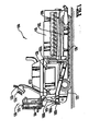
- a multi-use paving tractor generally designated 100, which includes a hopper and mixing apparatus 101, a conveying shaft 102, auger 109, driver station 120, driver seat 122, steering wheel 124, engine 126, chassis 127 and drive train 128.
- Items 101, 102, 109, 122, 124, 126, 127 and 128 are preferably similar or identical to components of prior art remixing road pavers such as described in the above- referenced U.S. patent and the prior art road paver manufactured by Cedarapids, Inc. of Cedar Rapids, Iowa.
- Engine 126 is drawn as a simple block, but it may include numerous related systems and/or components not limited to components of a hydraulic pump and system, an electrical system and other systems.
- One of the key aspects of these prior art pavers is that they do not exhibit the characteristics of dropping or dribbling asphalt from a return conveyor under the machine as is common in other prior art pavers.
- the elimination of dribbling from underneath the prior art paver was not perceived as a significant benefit because that machine and the machine described in the above-referenced patent were both dedicated pavers. Dribbles on the ground in front of a paver were not a problem because the paver covered these dribbles as the paver progressed forward.
- tractor 100 it is desirable that the tractor 100 not dribble asphalt on the ground as it progresses forward.
- the non-dribbling configuration of the above-referenced patent and the above-described paver is preferred.
- any other non-dribbling or low-dribbling mechanisms could be used in conjunction with the remainder of the present invention.
- a pull arm 103 is shown coupled to the tractor 100.
- a pull arm 103 is disposed on each side of the tractor.
- Pull arm 103 may include a quick connector 1032 disposed on or near a rear end 1031 of the pull arm 103.
- Pull-arm quick connector 1032 could be numerous types of connectors, such as a butt plate with holes for receiving bolts or pins, a channel for receiving an insert dropped in from above, a male or female connector, etc.
- Pull arm quick connector 1032 may have additional connectivity capability beyond structural connections, such as electric connections, hydraulic hose connections, etc. In any case, it is preferred that pull arm quick connector 1032 provide for the ability to add or remove attachments very quickly and while in the field.
- Hydraulic cylinders 1034 and 1035 or other mechanism for manipulating pull arm 103 between various raised and lowered positions are also shown.
- the pull arm 103 can be raised or lowered to engage tool attachments, discussed in detail below. While it may be preferred to utilize dual pull arms 103 on each side, it should be understood that a centrally disposed pull arm or group of centrally disposed pull arms could be used as well.
- the pull arm 103 is movable.
- An upper link 104 could be another connection between the tractor 100 and tool attachments.
- Upper link 104 if hydraulically extendable and retractable, could be used to connect, position and otherwise manipulate any tool attachment coupled to pull arm 103.(Note: that the upper link 104 may not be used on some attachments such as the screed.) An upper link 104 may be disposed on either side of the tractor 100, or a single upper link could be used as well. Appropriate driver controls 125 may be included to assist in the manipulation of pull arm 103 and upper link 104.
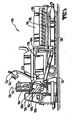
- FIG. 2 shows a multi-use paving tractor 100 of Figure 1 , together with an HMA mix transfer tool attachment, generally designated 200, which includes an elevator assembly 205, which collects remixed HMA from the rear of conveying shaft 102 and hopper and mixing apparatus 101 and elevates the HMA.
- Elevator assembly 205 includes elevator assembly lower connecting floor 206, which seals the elevator assembly 205 to the rear of the conveying shaft 102.
- Elevator assembly lower connecting floor 206 is where the HMA is collected prior to being elevated above the conveying shaft 102 by the elevator assembly 205.
- Elevator assembly slat conveyor 207 is shown disposed in elevator assembly 205.
- elevator assembly 205 is a preferred embodiment of the present invention. Alternate means and methods of elevating the HMA could be employed, such as augers, pumps and pipes or hoses, etc.
- the purpose of elevator assembly 205 is to collect the HMA and deliver it to swinging slat conveyor 209. However, it should be understood that elevator assembly 205 or its alternate means could be adjustable vertically and radially so as to eliminate the need for swinging slat conveyor 209.
- swinging slat conveyor 209 is a vertically and radially adjustable conveyor which can be swung to the right or the left upon swinging slat conveyor pivot support 211, which can be a hinge or other pivot support.
- Swinging slat conveyor 209 includes a swinging slat conveyor interior chain assembly 208 and a swinging slat conveyor raising mechanism 210 which can be disposed on one pull arm 103 or one side of the multi-use paving tractor 100, or it can have one on each side of multi-use paving tractor 100 or attached to right and left pull arms 103.
- Swinging slat conveyor raising mechanism 210 if mounted to a side of multi-use paving tractor 100, can both raise swinging slat conveyor 209 and swing swinging slat conveyor 209 right and left as needed.
- Swinging slat conveyor raising mechanism 210 can be a hydraulic cylinder, a cable/winch system or other system for lifting and swinging the swinging slat conveyor 209.
- Swinging slat conveyor pivot support 211 is preferably a support for pivoting about a horizontal axis and a vertical axis.
- a rotational coupling or independent orthogonal pivots could be used to enable swinging slat conveyor 209 to be both raised and swung as needed.
- FIG. 3 and 4 shows a right- or left-sided road widener attachment 300, which is preferably attached to multi-use paving tractor 100 via pull arm 103.
- elevator assembly 205 is used to elevate the HMA for distribution to a chute or cross conveyor 302.
- the HMA is then distributed alongside the multi-use paving tractor 100 so as to provide for road widening by road widener strike-off blade 417.
- the road width extension dimension 414 can be adjusted by manipulation of road widener strike-off blade angle control link 415, which controls the angle of road widener strike-off blade 417.
- the HMA is partially contained by road widener end gate assembly 413, which is adjusted by manipulation of road widener end gate angle control link 416.
- Right- or left-sided road widener attachment 300 is shown with few details because it is believed that numerous right- or left-sided road widener attachments 300 could be designed to meet the peculiar needs for various road types. It is believed that a person skilled in the art of making road wideners could readily adapt the above-described concept to work with most any particular road widening project type.
- road widener strike-off blade 417 could be made to pivot about both a horizontal axis and a vertical axis.
- Figure 5 shows a multi-use paving tractor 100 with a paver screed 518 attached thereto. It is believed that one skilled in the art given the description of the present invention could develop various paver screeds 518 to meet particular needs of various paving job types.
- a multi-use paving tractor 100 which accepts HMA in a hopper and mixing apparatus 101 and transports it rearward via conveying shaft 102.
- One of several attachments such as HMA mix transfer tool attachment, right- or left-sided road widener attachment 300 or paver screed 518 could be attached to the multi-use paving tractor 100, depending upon the needs at the time.
- the combination is then deployed and used on a road.
- the attachment then is removed and replaced with another of the several attachments and the new combination is used.
- Numerous road-paving tools can be deployed on one job without the need for redundant components.
- the removal and replacement process preferably can be done by either using a lift to pick up the attachment or raising the attachment and backing the multi-use paving tractor 100 to a trailer or platform where the attachment is then lowered and disconnected.
- Hopper and mixing apparatus 101 may comprise a rectangular box or an angled rectangular or circular bin or any shaped container and material mixing and transfer apparatus which is suitable for the paving material being used.
Abstract
Description
- The present invention generally relates to a method according to claim 1 or 2 using road paving equipment, and more particularly using pavers, and even more particularly using pavers with a capability for remixing hot mix asphalt (HMA) material placed in the hopper onboard the paver.
- In the past, road paving equipment designers have endeavored to improve the functionality of road pavers.
-
US Patent No. 6,481,925 discloses a work machine used in the paving industry. It includes a receiving portion that is adapted to receive a plurality of attachments. The receiving portion includes an aligning and fastening arrangement that can include both patterns, locating pins, mechanical or hydraulic clamps. The paving tractor is provided with a seat for the driver at the rear end, a hopper at the front, and means for conveying material from the hopper to the rear end. -
U.S. Patent 6,007,272 is an example of an improved paver with mixing capabilities. While such improvements have been made to remixing capabilities of pavers, they remain a single use machine. Most paving contractors will have a paver, a road widener and some means for transferring the mix to the paver and road widener, all of which are independent machines. - While these approaches of using independent pavers, road wideners and mix transfer machines, etc. have been used extensively in the past, they do have some drawbacks. First of all, they require significant investment Secondly, they require considerable space for storage and transportation.
- Consequently, there exists a need for improved methods for deploying multiple paving equipment tools.
-
EP 0469 272 B1 discloses a tractor having two pull arms. The pull arms are equipped with connector elements with which a paver screed or a road surface roughening screed can be attached. - The invention is defined in independent claims 1 and 2. Advantageous features are set forth in dependent claims 3 to 5.
- It is an object of the present invention to provide a method for deploying multiple paving equipment tools in an efficient manner.
- It is a feature of the present invention to utilize a multi-use paving tractor.
- It is an advantage of the present invention to reduce the cost of owning a group of paving tools.
- It is another advantage to permit multiple paving equipment tools to be stored in a smaller space.
- It is yet another advantage to permit reduced transportation costs in moving several paving tools to a job site.
- The present invention is a method for deploying multiple paving tools, designed to satisfy the aforementioned needs, provide the previously stated objects, include the above-listed features, and achieve the already articulated advantages. The present invention is carried out in a "redundant hardware-less" manner in a sense that the need to own, maintain and transport multiple paving hoppers, remixing equipment and propulsion mechanisms for a group of road paving tools, has been eliminated.
- Accordingly, the present invention is a method including a paving tractor with a capability for readily connecting and disconnecting a road paving tool thereto.
- The invention may be more fully understood by reading the following description of the preferred embodiments of the invention, in conjunction with the appended drawings wherein:
-
Figure 1 is an elevation view of the multi-use paving tractor, with a partial cut-away portion to reveal a plurality of augers. -
Figure 2 is an elevation view of the paving tractor ofFigure 1 , having an attached mix transfer tool. -
Figure 3 is an elevation view of the paving tractor ofFigure 1 , having an attached road widener tool. -
Figure 4 is a partial top view of the paving tractor and road widener tool ofFigure 3 . -
Figure 5 is an elevation view of the paving tractor ofFigure 1 , having an attached screed. - Now referring to the drawings wherein like numerals refer to like matter throughout, and more specifically referring to
Figure 1 , there is shown a multi-use paving tractor, generally designated 100, which includes a hopper and mixingapparatus 101, aconveying shaft 102,auger 109,driver station 120,driver seat 122,steering wheel 124,engine 126,chassis 127 anddrive train 128.Items Engine 126 is drawn as a simple block, but it may include numerous related systems and/or components not limited to components of a hydraulic pump and system, an electrical system and other systems. One of the key aspects of these prior art pavers is that they do not exhibit the characteristics of dropping or dribbling asphalt from a return conveyor under the machine as is common in other prior art pavers. The elimination of dribbling from underneath the prior art paver was not perceived as a significant benefit because that machine and the machine described in the above-referenced patent were both dedicated pavers. Dribbles on the ground in front of a paver were not a problem because the paver covered these dribbles as the paver progressed forward. However, for the present invention, it is desirable that thetractor 100 not dribble asphalt on the ground as it progresses forward. The non-dribbling configuration of the above-referenced patent and the above-described paver is preferred. However, it should be understood that any other non-dribbling or low-dribbling mechanisms could be used in conjunction with the remainder of the present invention. - A
pull arm 103 is shown coupled to thetractor 100. Preferably apull arm 103 is disposed on each side of the tractor.Pull arm 103 may include aquick connector 1032 disposed on or near arear end 1031 of thepull arm 103. Pull-armquick connector 1032 could be numerous types of connectors, such as a butt plate with holes for receiving bolts or pins, a channel for receiving an insert dropped in from above, a male or female connector, etc. Pull armquick connector 1032 may have additional connectivity capability beyond structural connections, such as electric connections, hydraulic hose connections, etc. In any case, it is preferred that pull armquick connector 1032 provide for the ability to add or remove attachments very quickly and while in the field. No welding and preferably no powered tools, other than those receiving power from themulti-use paving tractor 100 and a lift used to move the attachment, would be necessary.Hydraulic cylinders pull arm 103 between various raised and lowered positions are also shown. Thepull arm 103 can be raised or lowered to engage tool attachments, discussed in detail below. While it may be preferred to utilizedual pull arms 103 on each side, it should be understood that a centrally disposed pull arm or group of centrally disposed pull arms could be used as well. Thepull arm 103 is movable. Anupper link 104 could be another connection between thetractor 100 and tool attachments.Upper link 104, if hydraulically extendable and retractable, could be used to connect, position and otherwise manipulate any tool attachment coupled to pull arm 103.(Note: that theupper link 104 may not be used on some attachments such as the screed.) Anupper link 104 may be disposed on either side of thetractor 100, or a single upper link could be used as well.Appropriate driver controls 125 may be included to assist in the manipulation ofpull arm 103 andupper link 104. - A more detailed understanding of the present invention can be achieved by now referring to
Figure 2 , which shows amulti-use paving tractor 100 ofFigure 1 , together with an HMA mix transfer tool attachment, generally designated 200, which includes anelevator assembly 205, which collects remixed HMA from the rear of conveyingshaft 102 and hopper and mixingapparatus 101 and elevates the HMA.Elevator assembly 205 includes elevator assembly lower connectingfloor 206, which seals theelevator assembly 205 to the rear of theconveying shaft 102. Elevator assembly lower connectingfloor 206 is where the HMA is collected prior to being elevated above theconveying shaft 102 by theelevator assembly 205. Elevatorassembly slat conveyor 207 is shown disposed inelevator assembly 205. It should be understood that the depicted arrangement ofelevator assembly 205 is a preferred embodiment of the present invention. Alternate means and methods of elevating the HMA could be employed, such as augers, pumps and pipes or hoses, etc. The purpose ofelevator assembly 205 is to collect the HMA and deliver it to swinging slat conveyor 209. However, it should be understood thatelevator assembly 205 or its alternate means could be adjustable vertically and radially so as to eliminate the need for swinging slat conveyor 209. - In this preferred embodiment, swinging slat conveyor 209 is a vertically and radially adjustable conveyor which can be swung to the right or the left upon swinging slat conveyor pivot support 211, which can be a hinge or other pivot support. Swinging slat conveyor 209 includes a swinging slat conveyor interior chain assembly 208 and a swinging slat
conveyor raising mechanism 210 which can be disposed on onepull arm 103 or one side of themulti-use paving tractor 100, or it can have one on each side ofmulti-use paving tractor 100 or attached to right and left pullarms 103. Swinging slatconveyor raising mechanism 210, if mounted to a side ofmulti-use paving tractor 100, can both raise swinging slat conveyor 209 and swing swinging slat conveyor 209 right and left as needed. Swinging slatconveyor raising mechanism 210 can be a hydraulic cylinder, a cable/winch system or other system for lifting and swinging the swinging slat conveyor 209. - Swinging slat conveyor pivot support 211 is preferably a support for pivoting about a horizontal axis and a vertical axis. A rotational coupling or independent orthogonal pivots could be used to enable swinging slat conveyor 209 to be both raised and swung as needed.
- An even more detailed understanding of the present invention may be achieved by now referring to
Figures 3 and4 , which shows a right- or left-sidedroad widener attachment 300, which is preferably attached tomulti-use paving tractor 100 viapull arm 103. In this figure,elevator assembly 205 is used to elevate the HMA for distribution to a chute orcross conveyor 302. The HMA is then distributed alongside themulti-use paving tractor 100 so as to provide for road widening by road widener strike-off blade 417. The road width extension dimension 414 can be adjusted by manipulation of road widener strike-off bladeangle control link 415, which controls the angle of road widener strike-off blade 417. The HMA is partially contained by road widenerend gate assembly 413, which is adjusted by manipulation of road widener end gateangle control link 416. Right- or left-sidedroad widener attachment 300 is shown with few details because it is believed that numerous right- or left-sidedroad widener attachments 300 could be designed to meet the peculiar needs for various road types. It is believed that a person skilled in the art of making road wideners could readily adapt the above-described concept to work with most any particular road widening project type. For example, road widener strike-off blade 417 could be made to pivot about both a horizontal axis and a vertical axis. -
Figure 5 shows amulti-use paving tractor 100 with apaver screed 518 attached thereto. It is believed that one skilled in the art given the description of the present invention could developvarious paver screeds 518 to meet particular needs of various paving job types. - In operation, the method of the present invention as described in
Figures 1-5 , could function as follows: - Firstly, a
multi-use paving tractor 100 is provided which accepts HMA in a hopper and mixingapparatus 101 and transports it rearward via conveyingshaft 102. - One of several attachments, such as HMA mix transfer tool attachment, right- or left-sided
road widener attachment 300 orpaver screed 518 could be attached to themulti-use paving tractor 100, depending upon the needs at the time. The combination is then deployed and used on a road. The attachment then is removed and replaced with another of the several attachments and the new combination is used. Numerous road-paving tools can be deployed on one job without the need for redundant components. The removal and replacement process preferably can be done by either using a lift to pick up the attachment or raising the attachment and backing themulti-use paving tractor 100 to a trailer or platform where the attachment is then lowered and disconnected. - Throughout the above description, HMA is described as the material to be used. It should be understood that the present invention is directed to any type of road surface. It is believed that recycled asphalt products could be used, cold mix asphalt, and even in certain applications with any appropriate modifications, concrete could be the paving material. Hopper and mixing
apparatus 101 may comprise a rectangular box or an angled rectangular or circular bin or any shaped container and material mixing and transfer apparatus which is suitable for the paving material being used. - It is thought that the method of the present invention will be understood from the foregoing description and that it will be apparent that various changes may be made in the form, construct steps, and arrangement of the parts and steps thereof, without departing from the scope of the invention or sacrificing all of their material advantages. The form herein described is merely a preferred exemplary embodiment thereof.
Claims (5)
- A method of deploying multi-use road paving equipment comprising the steps of:providing a paving tractor (100) with a first detachable road paving tool attachment (518) operatively coupled thereto at a first connection point (1032), where said first connection point is on a vertically adjustable pull arm (103);replacing said first detachable road paving tool attachment (518) with a second detachable road paving tool attachment (200) without welding or cutting metal at said first connection point;where said first detachable road paving tool attachment (518) is configured to perform a substantially different task than said second detachable road paving tool attachment (200);wherein said first detachable road paving tool attachment is a paver screed (518) and said second detachable road paving tool attachment is a mix transfer tool attachment (200) which includes an elevator assembly (205), which collects remixed paving material from the rear of a conveying shaft and hopper (101) and mixing apparatus (101) and elevates the paving material;
and,wherein said paving tractor (100) is a self-propelled vehicle configured to be driven by a driver located on and at a rear end of said paving tractor (100), said paving tractor (100) further comprising the hopper (101) disposed forward of said rear end, and means for conveying paving material from said hopper (101) to said rear end. - A method of deploying multi-use road paving equipment comprising the steps of:providing a paving tractor (100) with a first detachable road paving tool attachment (518) operatively coupled thereto at a first connection point (1032), where said first connection point is on a vertically adjustable pull arm (103);replacing said first detachable road paving tool attachment (518) with a second detachable road paving tool attachment (300) without welding or cutting metal at said first connection point;where said first detachable road paving tool attachment (518) is configured to perform a substantially different task than said second detachable road paving tool attachment (300);wherein said first detachable road paving tool attachment is a paver screed (518) and said second detachable road paving tool attachment is a right- or left road widener attachment (300), which includes an elevator assembly (205) which collects remixed paving material from the rear of a conveying shaft and hopper (101) and mixing apparatus (101) and elevates the paving material for distribution to a chute or cross conveyoer (302) by which the paving material is then distributed alongside the multi use paving tractor (100) so as to provide for road widening by a road widener strike-off blade (417);
and,wherein said paving tractor (100) is a self-propelled vehicle configured to be driven by a driver located on and at a rear end of said paving tractor (100), said paving tractor (100) further comprising a hopper (101) disposed forward of said rear end, and means for conveying paving material from said hopper (101) to said rear end. - A method of claim 1 or 2 wherein said step of replacing comprises the steps of:causing said first detachable road paving tool attachment (518), while coupled to said paving tractor (100), to be disposed over a structural member disposed higher than a tractor operating surface upon which said paving tractor (100) is disposed;causing a vertical separation between said structural member and said first detachable road paving tool attachment (518) to decrease; and,
separating said first detachable road paving tool (200,300) from said paving tractor (100). - A method of claim 3 wherein said step of causing a vertical separation is accomplished by a manipulation of said vertically adjustable pull arm (103).
- A method of claim 4 where said step of replacing further comprises the steps of:mating said second detachable road paving tool attachment (200, 300) to said vertically adjustable pull arm (103); and,using a lifting force assisted by an engine (126) onboardsaid roadpaving tractor (100) to lift said second detachable road paving tool attachment (200, 300).
Applications Claiming Priority (2)
| Application Number | Priority Date | Filing Date | Title |
|---|---|---|---|
| US10/605,249 US20050058507A1 (en) | 2003-09-17 | 2003-09-17 | Multi-use paving tractor with tool attachments |
| US605249 | 2003-09-17 |
Publications (4)
| Publication Number | Publication Date |
|---|---|
| EP1516962A2 EP1516962A2 (en) | 2005-03-23 |
| EP1516962A3 EP1516962A3 (en) | 2005-08-31 |
| EP1516962B1 EP1516962B1 (en) | 2009-05-13 |
| EP1516962B2 true EP1516962B2 (en) | 2014-08-20 |
Family
ID=34193451
Family Applications (1)
| Application Number | Title | Priority Date | Filing Date |
|---|---|---|---|
| EP04254802.4A Not-in-force EP1516962B2 (en) | 2003-09-17 | 2004-08-10 | A method of deploying multi-use road paving equipment |
Country Status (5)
| Country | Link |
|---|---|
| US (2) | US20050058507A1 (en) |
| EP (1) | EP1516962B2 (en) |
| AT (1) | ATE431462T1 (en) |
| CA (1) | CA2472266C (en) |
| DE (1) | DE602004021072D1 (en) |
Families Citing this family (22)
| Publication number | Priority date | Publication date | Assignee | Title |
|---|---|---|---|---|
| CA2582210A1 (en) * | 2006-03-22 | 2007-09-22 | Cedarapids, Inc. | Multi-stage modular road paving equipment and method of manufacture and sales |
| US7785034B2 (en) * | 2008-06-26 | 2010-08-31 | Weiler, Inc. | Desegregation system |
| DE202010012456U1 (en) * | 2010-09-10 | 2011-12-12 | Smg Sportplatzmaschinenbau Gmbh | Ready-to-install with a storage container |
| US9089827B2 (en) | 2011-07-27 | 2015-07-28 | Res Usa Llc | Gasification system and method |
| US8506204B1 (en) | 2011-10-04 | 2013-08-13 | Quality Paving LLC | Strike-off accessory device, particularly for use with a vehicle |
| US8864388B2 (en) | 2012-05-01 | 2014-10-21 | Hewlett-Packard Development Company, L.P. | Faceplate apparatus and system for coupling to an electronic device |
| PL2711460T3 (en) * | 2012-09-21 | 2017-02-28 | Joseph Vögele AG | Construction machine with material conveyor system |
| CN102912712B (en) * | 2012-11-08 | 2015-06-10 | 河南万里路桥集团有限公司 | Cold-stirring and cold-paving all-in-one machine |
| CN103866677B (en) * | 2014-03-04 | 2016-05-11 | 湖南三一路面机械有限公司 | A kind of conveyer and milling machine |
| US9428869B2 (en) * | 2014-10-24 | 2016-08-30 | Gomaco Corporation | Adjustable width trail paver |
| DE102014018533B4 (en) | 2014-12-12 | 2023-09-28 | Bomag Gmbh | Method for controlling a work train |
| CN105908602B (en) * | 2016-06-27 | 2018-02-09 | 徐工集团工程机械股份有限公司道路机械分公司 | A kind of small-sized paver manipulation after-poppet |
| US10619402B2 (en) * | 2017-03-30 | 2020-04-14 | Carlson Paving Products, Inc. | Apparatus and method for a material control device with a sliding door |
| US10472777B1 (en) * | 2018-05-02 | 2019-11-12 | Caterpillar Paving Products Inc. | Screed tow point assembly for paver |
| US11060248B2 (en) * | 2018-12-06 | 2021-07-13 | Donelson Construction Co., Llc | Actuating resurfacing system and method |
| US11585049B2 (en) * | 2019-08-28 | 2023-02-21 | Caterpillar Paving Products Inc. | Overload support system for a paving machine screed assembly |
| DE102019133444A1 (en) * | 2019-12-06 | 2021-06-10 | Wirtgen Gmbh | Mobile soil cultivation machine, comprising a functional device that can preferably be releasably coupled to a machine frame without tools |
| CN115247391B (en) * | 2021-04-26 | 2023-07-04 | 山东省路桥集团有限公司 | Expansion auger mechanism of heat supplementing machine |
| CN113216581A (en) * | 2021-05-19 | 2021-08-06 | 江西木之歌装饰工程有限公司 | High-efficient laying device of concrete filling layer |
| CN113622266B (en) * | 2021-09-08 | 2022-07-05 | 中铁十九局集团第三工程有限公司 | Road surface asphalt construction device and method for road engineering |
| CN113996490B (en) * | 2021-11-22 | 2023-11-03 | 青岛科技大学 | Efficient automatic mixing construction device for bi-component coating and working method |
| CN113996491B (en) * | 2021-11-22 | 2023-11-03 | 青岛科技大学 | Mechanical control type continuous and automatic coating mixing and discharging construction device and working method |
Citations (1)
| Publication number | Priority date | Publication date | Assignee | Title |
|---|---|---|---|---|
| EP0469272B1 (en) † | 1990-08-03 | 1993-09-08 | Joseph Vögele AG | Process and apparatus for working road surfaces |
Family Cites Families (54)
| Publication number | Priority date | Publication date | Assignee | Title |
|---|---|---|---|---|
| US2067236A (en) * | 1934-01-22 | 1937-01-12 | Charles J Hepburn | Mixing machine |
| US3729824A (en) * | 1970-12-07 | 1973-05-01 | G A C International Inc | Orthodontic arch wire |
| US3901616A (en) * | 1974-07-22 | 1975-08-26 | Kenneth J Greening | Self-propelled paver |
| DE2712455C2 (en) * | 1977-03-22 | 1982-11-04 | Aeg-Elotherm Gmbh, 5630 Remscheid | Device for inductive quench hardening of bearing surfaces of a crankshaft |
| DE3120226A1 (en) * | 1981-05-21 | 1982-12-09 | Albert 8500 Nürnberg Friebel | DEVICE FOR REMOVING AND SMOOTHING THE SURFACE OF BOEDEN |
| US4420957A (en) * | 1981-10-26 | 1983-12-20 | Progressive Blasting Systems, Inc. | Monitor method and apparatus for particle blasting equipment |
| FI823299L (en) * | 1982-09-27 | 1984-03-28 | Uretaanitekniikka Oy | PROCEDURE FOR THE PURPOSE OF BUCKETS |
| US4646482A (en) * | 1985-11-12 | 1987-03-03 | Clements National Company | Recirculating sandblasting machine |
| US4702642A (en) * | 1986-07-25 | 1987-10-27 | Cedarapids, Inc. | Extensible screed assembly for a bituminous paver |
| GB8702354D0 (en) * | 1987-02-03 | 1987-03-11 | Kango Wolf Power Tools | Tool for stone-blowing |
| BR8707726A (en) * | 1987-04-10 | 1989-10-03 | Domenico Domenighetti | SPREADER-FINISHING PAVEMENTS FOR HIGHWAYS WITH A COMBINATION OF AXLES WITH SPEED WHEELS AND TRACK UNITS |
| US5035534A (en) * | 1987-08-25 | 1991-07-30 | Barber-Greene Company | Apparatus for transferring an asphalt-aggregate mixture |
| US5015120A (en) * | 1987-08-25 | 1991-05-14 | Barber-Greene Company | Methods and apparatus for making an asphalt-aggregate pavement |
| US4878320A (en) * | 1987-12-04 | 1989-11-07 | Whitemetal, Inc. | Abrasive feed system |
| US5123206A (en) * | 1987-12-04 | 1992-06-23 | Whitemetal, Inc. | Wet abrasive blasting method |
| US4839969A (en) * | 1988-02-26 | 1989-06-20 | Permian Research Corporation | Drying method and apparatus |
| US4865487A (en) * | 1988-06-16 | 1989-09-12 | Kenco Engineering, Inc. | Screed for asphalt paver |
| US4962913A (en) * | 1988-10-24 | 1990-10-16 | Stewart John V | Sidewalk lifter |
| US5325638A (en) * | 1989-07-07 | 1994-07-05 | Lynn William R | Pliant media blasting device |
| US4955754A (en) * | 1990-01-19 | 1990-09-11 | Barber-Greene Company | Shock absorbing device for a paving machine |
| US5230185A (en) * | 1990-04-06 | 1993-07-27 | Church & Dwight Co., Inc. | Blasting apparatus and method |
| US5083402A (en) * | 1990-04-06 | 1992-01-28 | Church & Dwight Co., Ind. | Blasting apparatus |
| US5081799A (en) * | 1990-04-06 | 1992-01-21 | Church & Dwight Co., Inc. | Blasting apparatus |
| FR2668512B1 (en) * | 1990-10-29 | 1993-04-09 | Franex Ste Nouvelle | MACHINE FOR IMPLEMENTING ROAD MATERIALS. |
| US5203642A (en) * | 1991-04-03 | 1993-04-20 | Barber-Greene Company | Extendable screed for an asphalt paver |
| US5201603A (en) * | 1991-05-17 | 1993-04-13 | Caterpillar Paving Products Inc. | Tow point for an asphalt paver |
| US5201604A (en) * | 1991-07-30 | 1993-04-13 | Raytheon Company | Field configurable sonic grade control |
| US5529434A (en) * | 1993-04-08 | 1996-06-25 | Swisher, Jr.; George W. | Paving material machine having hopper capacity and compensating tunnel capacity |
| USD362449S (en) * | 1993-07-09 | 1995-09-19 | Swisher Jr George W | Paving material machine with tunnel |
| US6514007B2 (en) * | 1993-11-27 | 2003-02-04 | Elk Richter | Finisher to lay and compact asphalt layers and method for operating same |
| US5533828A (en) * | 1994-09-29 | 1996-07-09 | Astec Industries, Inc. | Method and apparatus for discharging paving materials on top of distributing auger |
| US5553969A (en) * | 1995-02-13 | 1996-09-10 | Reed; Jeffrey | Paving apparatus |
| US5577446A (en) * | 1995-02-14 | 1996-11-26 | Pandrol Jackson, Inc. | Stoneblower having adjustable workheads and improved blowing tubes |
| US5522670A (en) * | 1995-03-15 | 1996-06-04 | Granite Rock Company | Hitching mechanism |
| CA2181969C (en) * | 1995-12-05 | 2007-07-17 | Charles G. Macku | Asphalt paver with remixing conveyor system |
| US6071040A (en) * | 1995-12-05 | 2000-06-06 | Cedarapids Inc., | Additive injection device for paving machines |
| DE19634013B4 (en) * | 1996-08-22 | 2015-02-05 | Joseph Vögele AG | Feeder for pavers |
| US5860783A (en) * | 1997-07-11 | 1999-01-19 | Corcoran; John | Cargo container storage and retrieval system and method including an on deck carriage assembly |
| US6079901A (en) * | 1997-08-12 | 2000-06-27 | Midland Machinery Co., Inc | Paving machine capable of spraying a liquid binding material |
| US6074129A (en) * | 1997-11-24 | 2000-06-13 | Caterpillar Inc. | Apparatus and method for securing a screed plate to a frame member of a screed assembly |
| US6203243B1 (en) * | 1998-02-03 | 2001-03-20 | Universal Screed Inc. | Two-stage paving screed extension |
| US6056474A (en) * | 1998-05-29 | 2000-05-02 | Caterpillar Inc. | Height control mechanism for strike-off plate of an asphalt paver screed assembly |
| US6612774B1 (en) * | 1999-05-11 | 2003-09-02 | Rick Dulin | Method and apparatus for compacting road shoulders |
| JP3383908B2 (en) * | 1999-06-15 | 2003-03-10 | 住友建機製造株式会社 | Screed device for road paving vehicles such as asphalt finishers |
| US6422785B1 (en) * | 1999-08-06 | 2002-07-23 | Rexcon-Division Of Rose Industries, Inc. | Track belt placer for placing construction materials and method for placing construction materials |
| ES1045144Y (en) * | 2000-02-07 | 2001-02-01 | Feixes Conrado Pont | MACHINE TO LEVEL MATERIALS ON THE FLOOR. |
| US6582152B2 (en) * | 2000-05-11 | 2003-06-24 | Leone Construction Company | Zero clearance variable width concrete paving machine |
| US6308785B1 (en) * | 2000-05-24 | 2001-10-30 | Rod Earl Rhoden | Adjustable grader-spreader bar |
| US20030219309A1 (en) * | 2000-07-13 | 2003-11-27 | Moore Mark C. | Apparatus and method for finishing concrete during a leveling process |
| US6481925B1 (en) * | 2000-11-01 | 2002-11-19 | Caterpillar Pavimg Products Inc | Paving work machine and method of transforming the same |
| US6543962B2 (en) * | 2001-03-29 | 2003-04-08 | Koch Industries, Inc. | Screed assembly with improved sensitivity and response to varying surface conditions |
| DE10155507B4 (en) * | 2001-11-13 | 2005-10-06 | Abg Allgemeine Baumaschinen-Gesellschaft Mbh | Finisher for the bottom-side installation of layers for roads od. Like. |
| US6712549B2 (en) * | 2002-07-09 | 2004-03-30 | Blaw-Knox Construction Equipment Corporation | Double-axis oscillating bogie wheels |
| US7311465B2 (en) * | 2005-03-10 | 2007-12-25 | Guntert & Zimmerman Const. Div., Inc. | Strike-off beam and spreader plow assembly for placer/spreader |
-
2003
- 2003-09-17 US US10/605,249 patent/US20050058507A1/en not_active Abandoned
-
2004
- 2004-06-25 CA CA2472266A patent/CA2472266C/en not_active Expired - Fee Related
- 2004-08-10 DE DE602004021072T patent/DE602004021072D1/en active Active
- 2004-08-10 AT AT04254802T patent/ATE431462T1/en not_active IP Right Cessation
- 2004-08-10 EP EP04254802.4A patent/EP1516962B2/en not_active Not-in-force
-
2011
- 2011-03-29 US US13/074,614 patent/US8025458B2/en not_active Expired - Fee Related
Patent Citations (1)
| Publication number | Priority date | Publication date | Assignee | Title |
|---|---|---|---|---|
| EP0469272B1 (en) † | 1990-08-03 | 1993-09-08 | Joseph Vögele AG | Process and apparatus for working road surfaces |
Non-Patent Citations (4)
| Title |
|---|
| DRUCKSCHRIFT VÖGELE SONDERBAUSTELLE PARABOLPROFIL † |
| DRUCKSCHRIFT VÖGELE SUPER 1502 DE OKT. 1995 † |
| DRUCKSCHRIFT VÖGELE SUPER 1603 DE NOV. 1995 † |
| Druckschrift VÖGELE SUPER 1804 DE Mai 1996 † |
Also Published As
| Publication number | Publication date |
|---|---|
| CA2472266C (en) | 2012-03-27 |
| DE602004021072D1 (en) | 2009-06-25 |
| US8025458B2 (en) | 2011-09-27 |
| EP1516962A3 (en) | 2005-08-31 |
| EP1516962A2 (en) | 2005-03-23 |
| US20050058507A1 (en) | 2005-03-17 |
| US20110176868A1 (en) | 2011-07-21 |
| ATE431462T1 (en) | 2009-05-15 |
| CA2472266A1 (en) | 2005-03-17 |
| EP1516962B1 (en) | 2009-05-13 |
Similar Documents
| Publication | Publication Date | Title |
|---|---|---|
| EP1516962B2 (en) | A method of deploying multi-use road paving equipment | |
| US7458747B2 (en) | Frame raising multi-use paving tractor with blind mateable quick connecting tool attachments | |
| US5441361A (en) | Field convertible apparatus for conducting either front load road planing operation or cold in-place recycling operation | |
| CA2346600C (en) | Improved folding pusher | |
| US5344254A (en) | Pivoting screed edger | |
| EP3237253B1 (en) | Material transfer vehicle having an expandable truck-receiving hopper | |
| JPS62276104A (en) | Asphalt paving machine | |
| CA3062182C (en) | Quick-change attachment for material transfer vehicle | |
| US5522670A (en) | Hitching mechanism | |
| US20070065230A1 (en) | Self Propelled Remix Machine with Conveyor | |
| US6176551B1 (en) | Surface preparation apparatus and method of using the same | |
| EP1891272B1 (en) | Material transfer vehicle for use in asphalt paving | |
| CA2565506C (en) | A frame raising multi-use paving tractor with blind mateable quick connecting tool attachments | |
| US20200156872A1 (en) | Flexible hopper for a conveyor system | |
| AU2020392084B2 (en) | Road working machine with egress lighting system | |
| US5215403A (en) | Machine for transferring paving material | |
| US3743432A (en) | Automated paving machine | |
| WO1998046472A1 (en) | Tractor unit and wheeled trailer combination | |
| EP0624690B1 (en) | Machine for grading road surfaces | |
| JPH03199510A (en) | Asphalt mixture supply controller in on-road cutting mixer |
Legal Events
| Date | Code | Title | Description |
|---|---|---|---|
| PUAI | Public reference made under article 153(3) epc to a published international application that has entered the european phase |
Free format text: ORIGINAL CODE: 0009012 |
|
| AK | Designated contracting states |
Kind code of ref document: A2 Designated state(s): AT BE BG CH CY CZ DE DK EE ES FI FR GB GR HU IE IT LI LU MC NL PL PT RO SE SI SK TR |
|
| AX | Request for extension of the european patent |
Extension state: AL HR LT LV MK |
|
| PUAL | Search report despatched |
Free format text: ORIGINAL CODE: 0009013 |
|
| AK | Designated contracting states |
Kind code of ref document: A3 Designated state(s): AT BE BG CH CY CZ DE DK EE ES FI FR GB GR HU IE IT LI LU MC NL PL PT RO SE SI SK TR |
|
| AX | Request for extension of the european patent |
Extension state: AL HR LT LV MK |
|
| 17P | Request for examination filed |
Effective date: 20060227 |
|
| AKX | Designation fees paid |
Designated state(s): AT BE BG CH CY CZ DE DK EE ES FI FR GB GR HU IE IT LI LU MC NL PL PT RO SE SI SK TR |
|
| 17Q | First examination report despatched |
Effective date: 20080414 |
|
| GRAP | Despatch of communication of intention to grant a patent |
Free format text: ORIGINAL CODE: EPIDOSNIGR1 |
|
| GRAP | Despatch of communication of intention to grant a patent |
Free format text: ORIGINAL CODE: EPIDOSNIGR1 |
|
| GRAS | Grant fee paid |
Free format text: ORIGINAL CODE: EPIDOSNIGR3 |
|
| GRAA | (expected) grant |
Free format text: ORIGINAL CODE: 0009210 |
|
| AK | Designated contracting states |
Kind code of ref document: B1 Designated state(s): AT BE BG CH CY CZ DE DK EE ES FI FR GB GR HU IE IT LI LU MC NL PL PT RO SE SI SK TR |
|
| REG | Reference to a national code |
Ref country code: GB Ref legal event code: FG4D |
|
| REG | Reference to a national code |
Ref country code: CH Ref legal event code: EP |
|
| REG | Reference to a national code |
Ref country code: IE Ref legal event code: FG4D |
|
| REF | Corresponds to: |
Ref document number: 602004021072 Country of ref document: DE Date of ref document: 20090625 Kind code of ref document: P |
|
| PG25 | Lapsed in a contracting state [announced via postgrant information from national office to epo] |
Ref country code: PT Free format text: LAPSE BECAUSE OF FAILURE TO SUBMIT A TRANSLATION OF THE DESCRIPTION OR TO PAY THE FEE WITHIN THE PRESCRIBED TIME-LIMIT Effective date: 20090913 Ref country code: ES Free format text: LAPSE BECAUSE OF FAILURE TO SUBMIT A TRANSLATION OF THE DESCRIPTION OR TO PAY THE FEE WITHIN THE PRESCRIBED TIME-LIMIT Effective date: 20090824 Ref country code: AT Free format text: LAPSE BECAUSE OF FAILURE TO SUBMIT A TRANSLATION OF THE DESCRIPTION OR TO PAY THE FEE WITHIN THE PRESCRIBED TIME-LIMIT Effective date: 20090513 Ref country code: FI Free format text: LAPSE BECAUSE OF FAILURE TO SUBMIT A TRANSLATION OF THE DESCRIPTION OR TO PAY THE FEE WITHIN THE PRESCRIBED TIME-LIMIT Effective date: 20090513 |
|
| NLV1 | Nl: lapsed or annulled due to failure to fulfill the requirements of art. 29p and 29m of the patents act | ||
| PG25 | Lapsed in a contracting state [announced via postgrant information from national office to epo] |
Ref country code: PL Free format text: LAPSE BECAUSE OF FAILURE TO SUBMIT A TRANSLATION OF THE DESCRIPTION OR TO PAY THE FEE WITHIN THE PRESCRIBED TIME-LIMIT Effective date: 20090513 Ref country code: NL Free format text: LAPSE BECAUSE OF FAILURE TO SUBMIT A TRANSLATION OF THE DESCRIPTION OR TO PAY THE FEE WITHIN THE PRESCRIBED TIME-LIMIT Effective date: 20090513 Ref country code: SE Free format text: LAPSE BECAUSE OF FAILURE TO SUBMIT A TRANSLATION OF THE DESCRIPTION OR TO PAY THE FEE WITHIN THE PRESCRIBED TIME-LIMIT Effective date: 20090813 Ref country code: SI Free format text: LAPSE BECAUSE OF FAILURE TO SUBMIT A TRANSLATION OF THE DESCRIPTION OR TO PAY THE FEE WITHIN THE PRESCRIBED TIME-LIMIT Effective date: 20090513 |
|
| PG25 | Lapsed in a contracting state [announced via postgrant information from national office to epo] |
Ref country code: RO Free format text: LAPSE BECAUSE OF FAILURE TO SUBMIT A TRANSLATION OF THE DESCRIPTION OR TO PAY THE FEE WITHIN THE PRESCRIBED TIME-LIMIT Effective date: 20090513 Ref country code: EE Free format text: LAPSE BECAUSE OF FAILURE TO SUBMIT A TRANSLATION OF THE DESCRIPTION OR TO PAY THE FEE WITHIN THE PRESCRIBED TIME-LIMIT Effective date: 20090513 Ref country code: DK Free format text: LAPSE BECAUSE OF FAILURE TO SUBMIT A TRANSLATION OF THE DESCRIPTION OR TO PAY THE FEE WITHIN THE PRESCRIBED TIME-LIMIT Effective date: 20090513 Ref country code: CZ Free format text: LAPSE BECAUSE OF FAILURE TO SUBMIT A TRANSLATION OF THE DESCRIPTION OR TO PAY THE FEE WITHIN THE PRESCRIBED TIME-LIMIT Effective date: 20090513 |
|
| PLBI | Opposition filed |
Free format text: ORIGINAL CODE: 0009260 |
|
| PG25 | Lapsed in a contracting state [announced via postgrant information from national office to epo] |
Ref country code: BE Free format text: LAPSE BECAUSE OF FAILURE TO SUBMIT A TRANSLATION OF THE DESCRIPTION OR TO PAY THE FEE WITHIN THE PRESCRIBED TIME-LIMIT Effective date: 20090513 Ref country code: SK Free format text: LAPSE BECAUSE OF FAILURE TO SUBMIT A TRANSLATION OF THE DESCRIPTION OR TO PAY THE FEE WITHIN THE PRESCRIBED TIME-LIMIT Effective date: 20090513 |
|
| PLAX | Notice of opposition and request to file observation + time limit sent |
Free format text: ORIGINAL CODE: EPIDOSNOBS2 |
|
| 26 | Opposition filed |
Opponent name: JOSEPH VOEGELE AG Effective date: 20100212 |
|
| PG25 | Lapsed in a contracting state [announced via postgrant information from national office to epo] |
Ref country code: MC Free format text: LAPSE BECAUSE OF NON-PAYMENT OF DUE FEES Effective date: 20090831 Ref country code: BG Free format text: LAPSE BECAUSE OF FAILURE TO SUBMIT A TRANSLATION OF THE DESCRIPTION OR TO PAY THE FEE WITHIN THE PRESCRIBED TIME-LIMIT Effective date: 20090813 |
|
| REG | Reference to a national code |
Ref country code: CH Ref legal event code: PL |
|
| PG25 | Lapsed in a contracting state [announced via postgrant information from national office to epo] |
Ref country code: LI Free format text: LAPSE BECAUSE OF NON-PAYMENT OF DUE FEES Effective date: 20090831 Ref country code: CH Free format text: LAPSE BECAUSE OF NON-PAYMENT OF DUE FEES Effective date: 20090831 |
|
| REG | Reference to a national code |
Ref country code: IE Ref legal event code: MM4A |
|
| PLAF | Information modified related to communication of a notice of opposition and request to file observations + time limit |
Free format text: ORIGINAL CODE: EPIDOSCOBS2 |
|
| PG25 | Lapsed in a contracting state [announced via postgrant information from national office to epo] |
Ref country code: IE Free format text: LAPSE BECAUSE OF NON-PAYMENT OF DUE FEES Effective date: 20090810 |
|
| PLBB | Reply of patent proprietor to notice(s) of opposition received |
Free format text: ORIGINAL CODE: EPIDOSNOBS3 |
|
| PG25 | Lapsed in a contracting state [announced via postgrant information from national office to epo] |
Ref country code: GR Free format text: LAPSE BECAUSE OF FAILURE TO SUBMIT A TRANSLATION OF THE DESCRIPTION OR TO PAY THE FEE WITHIN THE PRESCRIBED TIME-LIMIT Effective date: 20090814 |
|
| PG25 | Lapsed in a contracting state [announced via postgrant information from national office to epo] |
Ref country code: IT Free format text: LAPSE BECAUSE OF FAILURE TO SUBMIT A TRANSLATION OF THE DESCRIPTION OR TO PAY THE FEE WITHIN THE PRESCRIBED TIME-LIMIT Effective date: 20090513 |
|
| PG25 | Lapsed in a contracting state [announced via postgrant information from national office to epo] |
Ref country code: LU Free format text: LAPSE BECAUSE OF NON-PAYMENT OF DUE FEES Effective date: 20090810 |
|
| PG25 | Lapsed in a contracting state [announced via postgrant information from national office to epo] |
Ref country code: HU Free format text: LAPSE BECAUSE OF FAILURE TO SUBMIT A TRANSLATION OF THE DESCRIPTION OR TO PAY THE FEE WITHIN THE PRESCRIBED TIME-LIMIT Effective date: 20091114 |
|
| PG25 | Lapsed in a contracting state [announced via postgrant information from national office to epo] |
Ref country code: TR Free format text: LAPSE BECAUSE OF FAILURE TO SUBMIT A TRANSLATION OF THE DESCRIPTION OR TO PAY THE FEE WITHIN THE PRESCRIBED TIME-LIMIT Effective date: 20090513 |
|
| PG25 | Lapsed in a contracting state [announced via postgrant information from national office to epo] |
Ref country code: CY Free format text: LAPSE BECAUSE OF FAILURE TO SUBMIT A TRANSLATION OF THE DESCRIPTION OR TO PAY THE FEE WITHIN THE PRESCRIBED TIME-LIMIT Effective date: 20090513 |
|
| PLAB | Opposition data, opponent's data or that of the opponent's representative modified |
Free format text: ORIGINAL CODE: 0009299OPPO |
|
| R26 | Opposition filed (corrected) |
Opponent name: JOSEPH VOEGELE AG Effective date: 20100212 |
|
| PGFP | Annual fee paid to national office [announced via postgrant information from national office to epo] |
Ref country code: GB Payment date: 20120828 Year of fee payment: 9 |
|
| PGFP | Annual fee paid to national office [announced via postgrant information from national office to epo] |
Ref country code: FR Payment date: 20120830 Year of fee payment: 9 |
|
| REG | Reference to a national code |
Ref country code: DE Ref legal event code: R082 Ref document number: 602004021072 Country of ref document: DE Representative=s name: HOESSLE PATENTANWAELTE PARTNERSCHAFT, DE |
|
| REG | Reference to a national code |
Ref country code: DE Ref legal event code: R081 Ref document number: 602004021072 Country of ref document: DE Owner name: CMI TEREX CORP., US Free format text: FORMER OWNER: CEDARAPIDS, INC., CEDAR RAPIDS, US Effective date: 20130311 Ref country code: DE Ref legal event code: R082 Ref document number: 602004021072 Country of ref document: DE Representative=s name: HOESSLE PATENTANWAELTE PARTNERSCHAFT, DE Effective date: 20130311 Ref country code: DE Ref legal event code: R082 Ref document number: 602004021072 Country of ref document: DE Representative=s name: LANG & TOMERIUS PATENTANWALTSPARTNERSCHFT MBB, DE Effective date: 20130311 Ref country code: DE Ref legal event code: R082 Ref document number: 602004021072 Country of ref document: DE Representative=s name: LANG & TOMERIUS PATENTANWALTSPARTNERSCHAFT MBB, DE Effective date: 20130311 Ref country code: DE Ref legal event code: R081 Ref document number: 602004021072 Country of ref document: DE Owner name: CMI TEREX CORP., MOORE, US Free format text: FORMER OWNER: CEDARAPIDS, INC., CEDAR RAPIDS, IA., US Effective date: 20130311 Ref country code: DE Ref legal event code: R082 Ref document number: 602004021072 Country of ref document: DE Representative=s name: PATENTANWAELTE LANG & TOMERIUS, DE Effective date: 20130311 |
|
| RAP2 | Party data changed (patent owner data changed or rights of a patent transferred) |
Owner name: CMI TEREX CORPORATION |
|
| PLAY | Examination report in opposition despatched + time limit |
Free format text: ORIGINAL CODE: EPIDOSNORE2 |
|
| REG | Reference to a national code |
Ref country code: DE Ref legal event code: R082 Ref document number: 602004021072 Country of ref document: DE Representative=s name: PATENTANWAELTE LANG & TOMERIUS, DE Ref country code: DE Ref legal event code: R082 Ref document number: 602004021072 Country of ref document: DE Representative=s name: LANG & TOMERIUS PATENTANWALTSPARTNERSCHFT MBB, DE Ref country code: DE Ref legal event code: R082 Ref document number: 602004021072 Country of ref document: DE Representative=s name: LANG & TOMERIUS PATENTANWALTSPARTNERSCHAFT MBB, DE |
|
| REG | Reference to a national code |
Ref country code: GB Ref legal event code: 732E Free format text: REGISTERED BETWEEN 20130808 AND 20130814 |
|
| APBM | Appeal reference recorded |
Free format text: ORIGINAL CODE: EPIDOSNREFNO |
|
| APBP | Date of receipt of notice of appeal recorded |
Free format text: ORIGINAL CODE: EPIDOSNNOA2O |
|
| REG | Reference to a national code |
Ref country code: FR Ref legal event code: TP Owner name: CEDARAPIDS, INC., US Effective date: 20130826 |
|
| APAH | Appeal reference modified |
Free format text: ORIGINAL CODE: EPIDOSCREFNO |
|
| APBU | Appeal procedure closed |
Free format text: ORIGINAL CODE: EPIDOSNNOA9O |
|
| GBPC | Gb: european patent ceased through non-payment of renewal fee |
Effective date: 20130810 |
|
| REG | Reference to a national code |
Ref country code: FR Ref legal event code: ST Effective date: 20140430 |
|
| PUAH | Patent maintained in amended form |
Free format text: ORIGINAL CODE: 0009272 |
|
| STAA | Information on the status of an ep patent application or granted ep patent |
Free format text: STATUS: PATENT MAINTAINED AS AMENDED |
|
| PG25 | Lapsed in a contracting state [announced via postgrant information from national office to epo] |
Ref country code: GB Free format text: LAPSE BECAUSE OF NON-PAYMENT OF DUE FEES Effective date: 20130810 |
|
| 27A | Patent maintained in amended form |
Effective date: 20140820 |
|
| AK | Designated contracting states |
Kind code of ref document: B2 Designated state(s): AT BE BG CH CY CZ DE DK EE ES FI FR GB GR HU IE IT LI LU MC NL PL PT RO SE SI SK TR |
|
| REG | Reference to a national code |
Ref country code: DE Ref legal event code: R102 Ref document number: 602004021072 Country of ref document: DE |
|
| PG25 | Lapsed in a contracting state [announced via postgrant information from national office to epo] |
Ref country code: FR Free format text: LAPSE BECAUSE OF NON-PAYMENT OF DUE FEES Effective date: 20130902 |
|
| REG | Reference to a national code |
Ref country code: DE Ref legal event code: R102 Ref document number: 602004021072 Country of ref document: DE Effective date: 20140820 |
|
| PGFP | Annual fee paid to national office [announced via postgrant information from national office to epo] |
Ref country code: DE Payment date: 20210819 Year of fee payment: 18 |
|
| REG | Reference to a national code |
Ref country code: DE Ref legal event code: R119 Ref document number: 602004021072 Country of ref document: DE |
|
| PG25 | Lapsed in a contracting state [announced via postgrant information from national office to epo] |
Ref country code: DE Free format text: LAPSE BECAUSE OF NON-PAYMENT OF DUE FEES Effective date: 20230301 |