US8469616B2 - Printer with cutter - Google Patents
Printer with cutter Download PDFInfo
- Publication number
- US8469616B2 US8469616B2 US12/592,863 US59286309A US8469616B2 US 8469616 B2 US8469616 B2 US 8469616B2 US 59286309 A US59286309 A US 59286309A US 8469616 B2 US8469616 B2 US 8469616B2
- Authority
- US
- United States
- Prior art keywords
- frame
- main body
- blade
- movable blade
- blade frame
- Prior art date
- Legal status (The legal status is an assumption and is not a legal conclusion. Google has not performed a legal analysis and makes no representation as to the accuracy of the status listed.)
- Expired - Fee Related, expires
Links
Images


Classifications
-
- B—PERFORMING OPERATIONS; TRANSPORTING
- B26—HAND CUTTING TOOLS; CUTTING; SEVERING
- B26D—CUTTING; DETAILS COMMON TO MACHINES FOR PERFORATING, PUNCHING, CUTTING-OUT, STAMPING-OUT OR SEVERING
- B26D7/00—Details of apparatus for cutting, cutting-out, stamping-out, punching, perforating, or severing by means other than cutting
-
- B—PERFORMING OPERATIONS; TRANSPORTING
- B26—HAND CUTTING TOOLS; CUTTING; SEVERING
- B26D—CUTTING; DETAILS COMMON TO MACHINES FOR PERFORATING, PUNCHING, CUTTING-OUT, STAMPING-OUT OR SEVERING
- B26D1/00—Cutting through work characterised by the nature or movement of the cutting member or particular materials not otherwise provided for; Apparatus or machines therefor; Cutting members therefor
- B26D1/01—Cutting through work characterised by the nature or movement of the cutting member or particular materials not otherwise provided for; Apparatus or machines therefor; Cutting members therefor involving a cutting member which does not travel with the work
- B26D1/04—Cutting through work characterised by the nature or movement of the cutting member or particular materials not otherwise provided for; Apparatus or machines therefor; Cutting members therefor involving a cutting member which does not travel with the work having a linearly-movable cutting member
- B26D1/06—Cutting through work characterised by the nature or movement of the cutting member or particular materials not otherwise provided for; Apparatus or machines therefor; Cutting members therefor involving a cutting member which does not travel with the work having a linearly-movable cutting member wherein the cutting member reciprocates
- B26D1/08—Cutting through work characterised by the nature or movement of the cutting member or particular materials not otherwise provided for; Apparatus or machines therefor; Cutting members therefor involving a cutting member which does not travel with the work having a linearly-movable cutting member wherein the cutting member reciprocates of the guillotine type
- B26D1/085—Cutting through work characterised by the nature or movement of the cutting member or particular materials not otherwise provided for; Apparatus or machines therefor; Cutting members therefor involving a cutting member which does not travel with the work having a linearly-movable cutting member wherein the cutting member reciprocates of the guillotine type for thin material, e.g. for sheets, strips or the like
-
- B—PERFORMING OPERATIONS; TRANSPORTING
- B41—PRINTING; LINING MACHINES; TYPEWRITERS; STAMPS
- B41J—TYPEWRITERS; SELECTIVE PRINTING MECHANISMS, i.e. MECHANISMS PRINTING OTHERWISE THAN FROM A FORME; CORRECTION OF TYPOGRAPHICAL ERRORS
- B41J11/00—Devices or arrangements of selective printing mechanisms, e.g. ink-jet printers or thermal printers, for supporting or handling copy material in sheet or web form
- B41J11/006—Means for preventing paper jams or for facilitating their removal
-
- B—PERFORMING OPERATIONS; TRANSPORTING
- B41—PRINTING; LINING MACHINES; TYPEWRITERS; STAMPS
- B41J—TYPEWRITERS; SELECTIVE PRINTING MECHANISMS, i.e. MECHANISMS PRINTING OTHERWISE THAN FROM A FORME; CORRECTION OF TYPOGRAPHICAL ERRORS
- B41J11/00—Devices or arrangements of selective printing mechanisms, e.g. ink-jet printers or thermal printers, for supporting or handling copy material in sheet or web form
- B41J11/66—Applications of cutting devices
- B41J11/70—Applications of cutting devices cutting perpendicular to the direction of paper feed
-
- B—PERFORMING OPERATIONS; TRANSPORTING
- B26—HAND CUTTING TOOLS; CUTTING; SEVERING
- B26D—CUTTING; DETAILS COMMON TO MACHINES FOR PERFORATING, PUNCHING, CUTTING-OUT, STAMPING-OUT OR SEVERING
- B26D5/00—Arrangements for operating and controlling machines or devices for cutting, cutting-out, stamping-out, punching, perforating, or severing by means other than cutting
- B26D5/02—Means for moving the cutting member into its operative position for cutting
-
- B—PERFORMING OPERATIONS; TRANSPORTING
- B26—HAND CUTTING TOOLS; CUTTING; SEVERING
- B26D—CUTTING; DETAILS COMMON TO MACHINES FOR PERFORATING, PUNCHING, CUTTING-OUT, STAMPING-OUT OR SEVERING
- B26D7/00—Details of apparatus for cutting, cutting-out, stamping-out, punching, perforating, or severing by means other than cutting
- B26D7/26—Means for mounting or adjusting the cutting member; Means for adjusting the stroke of the cutting member
- B26D7/2614—Means for mounting the cutting member
Definitions
- the present invention relates to a printer with a cutter, which can appropriately cut a recording sheet drawn out of a paper roll after printing is performed on the recording sheet.
- thermal printers in which printing is performed by pressing a thermal head against a special recording sheet (heat-sensitive sheet) which changes in color when heat is applied thereto, and by developing color on the recording sheet by heating.
- heat-sensitive sheet which changes in color when heat is applied thereto
- smooth characters and multicolor graphics can be printed without using toner, ink, and the like, and hence the thermal printers are preferably used for printing of various kinds of labels, receipts, and tickets.
- the cutter mechanism includes a fixed blade and a movable blade capable of sliding with respect to the fixed blade. Further, when the recording sheet is cut, the movable blade is slid so as to climb onto an upper surface of the fixed blade. With this, the recording sheet can be cut while being sandwiched between cutting edges of the both blades as the recording sheet is cut with a pair of scissors.
- the cutter mechanism is incorporated into the thermal printer
- an integrated type structure in which a cutter unit including the fixed blade and the movable blade integrated with each other is incorporated to a main body unit
- a clamshell type structure in which a detachable unit is detachably provided to the main body unit, and the fixed blade is incorporated into one of the main body unit and the detachable unit and the movable blade is incorporated into the other one of the main body unit and the detachable unit, and thus the fixed blade and the movable blade can be separated from each other.
- a clamshell thermal printer including a main body unit having a movable blade, and a detachable unit having a fixed blade, in which both the main body unit and the detachable unit can turn in a direction orthogonal to a sliding direction of the movable blade, and the main body unit moves to a cutting position while pressurizing the detachable unit when the main body unit turns.
- the present invention has been made in view of the above-mentioned circumstances, and an object of the present invention is therefore to provide a printer with a cutter, which can easily restore, even when there arises a problem that the movable blade is stopped during sliding due to paper jam or the like, the movable blade to the state before the problem arises, reliably perform positioning between the movable blade frame and the detachable unit, and improve printing accuracy and cutting accuracy.
- the present invention provides the following techniques.
- a printer with a cutter for cutting a recording sheet after printing is performed on the recording sheet, the cutter including a fixed blade and a movable blade which are arranged to be opposed to each other while sandwiching a passing surface for the recording sheet, the movable blade sliding toward the fixed blade and being capable of cutting the recording sheet while sandwiching the recording sheet between the fixed blade and the movable blade.
- the printer with the cutter includes: a movable blade frame for slidably supporting the movable blade; a main body frame for supporting one of a print head and a platen roller; a main body unit configured by incorporating the movable blade frame to the main body frame; and a detachable unit detachably provided to the main body unit, in which the fixed blade is incorporated, and by which another one of the print head and the platen roller is supported, in which: the detachable unit is movable in a sliding direction of the movable blade from a mounted position, at which the detachable unit is mounted to the main body unit, to a dismounted position, at which the detachable unit is detached from the main body unit; and the movable blade frame is movable in a direction orthogonal to the sliding direction of the movable blade from a home position, at which the movable blade frame is incorporated to the main body frame, to a separated position, at which the movable blade frame is separated from the main body frame.
- the movable blade frame moves in the direction orthogonal to the sliding direction of the movable blade. Accordingly, the movable blade and the fixed blade retreat in directions orthogonal to each other, respectively. That is, a contact pressure between both blades is promptly released when the detachable unit and the movable blade frame move.
- a printer with the cutter according to the present invention further includes: a rack provided integrally with the movable blade; a drive means provided in the main body frame, for sliding the movable blade; and a gear train mechanism for transmitting a drive force from the drive means to the rack, in which: the gear train mechanism and the rack are meshed with each other at the home position of the movable blade frame; and meshing between the gear train mechanism and the rack is released at the separated position of the movable blade frame.
- a biasing means for biasing the movable blade in a direction of separating the movable blade from the fixed blade is provided between the movable blade and the movable blade frame.
- the movable blade is biased in the direction of separating from the fixed blade.
- the movable blade automatically retreats to the initial position. Therefore, through easy manipulation of merely moving the movable blade frame to the retreat position, restoring work for the movable blade can be performed as well, and hence it is possible to improve operativity, and to alleviate a burden on a user.
- a biasing means for biasing the movable blade frame to the separated position is provided between the movable blade frame and the main body frame.
- the movable blade frame is biased toward the separated position, and hence it is possible to automatically move the movable blade frame to the separated position after the movable blade frame is released from the home position. Therefore, it is possible to perform restoring work for the movable blade more easily, and to improve operativity.
- the main body unit is incorporated into a casing having an opening from which the recording sheet is received, and a stopper for preventing the movable blade from protruding from the movable blade frame at the separated position of the movable blade frame is formed in the casing.
- the stopper is formed in the casing, and hence it is possible to prevent the movable blade from protruding from the movable blade frame at the separated position of the movable blade frame.
- the detachable unit includes a lever member capable of turning about a shaft, the lever member including a lock pin protruding in a width direction of the fixed blade
- the main body frame includes a first recess for receiving the shaft in a state in which the detachable unit is at the mounted position, and a second recess for receiving the lock pin in the state in which the detachable unit is at the mounted position, a first regulating portion for regulating movement of the shaft in the state in which the detachable unit is at the mounted position is formed at an inner peripheral edge of the first recess, and a second regulating portion for regulating movement of the lock pin in the state in which the detachable unit is at the mounted position is formed at an inner peripheral edge of the second recess, the second regulating portion being formed such that the lock pin is capable of slipping out of the second recess when the lever member turns about the shaft.
- the detachable unit in a state in which the shaft and the lock pin are regulated in the movement by the first regulating portion of the first recess and the second regulating portion of the second recess at the mounted position, respectively, the detachable unit is mounted to the main body frame.
- the detachable unit merely by turning the lever member about the shaft, regulation against the lock pin by the second regulating portion is canceled, and the lock pin slips out of the second recess. With this, locking between the detachable unit and the main body frame is canceled, and thus it is possible to easily detach the detachable unit from the main body frame.
- the movable blade frame includes a third recess to be engaged with the shaft together with the first recess of the main body frame in a state at the home position, and a guide portion for guiding the shaft such that the movable blade frame moves to the home position when the detachable unit moves to the mounted position, and for guiding the shaft such that the detachable unit moves to the dismounted position when the movable blade frame moves to the separated position is formed at an inner peripheral edge of the third recess.
- the shaft provided in the detachable unit is engaged in the third recess of the movable blade frame with the first recess, and hence it is possible to stably hold the detachable unit to the main body frame and the movable blade frame.
- the shaft can be brought to one side in the first recess by the guide portion, and positioning between the detachable unit and the movable blade frame is reliably performed.
- the movable blade can be held in press-contact with the fixed blade at a moderate contact pressure.
- it is possible to perform stable cutting operation by the both blades, and to improve cutting accuracy.
- a biasing means for biasing the movable blade frame to the home position is provided between the movable blade frame and the main body frame.
- the movable blade frame is biased toward the home position.
- the movable blade frame is at the home position, it is possible to stably hold the movable blade frame with respect to the main body frame without backlash.
- the detachable unit includes an engagement pin protruding in a width direction of the fixed blade
- the main body frame includes a recess for receiving the engagement pin in a state in which the detachable unit is at the mounted position
- the movable blade frame includes a hook portion to be engaged in the recess with the engagement pin in a state at the home position.
- the engagement pin provided in the detachable unit is engaged with the recess and the hook portion while being sandwiched therebetween.
- a paper powder accumulating portion for collecting paper powder generated when the recording sheet is cut is provided between the movable blade frame and the main body frame.
- the paper powder accumulating portion is provided between the main body frame and the movable blade frame.
- the paper powder which is generated when the recording sheet is cut, falls downward due to impact or the like at the time of cutting operation and moving of the movable blade frame between the home position and the separated position, to thereby be received in the paper powder accumulating portion. Therefore, the paper powder does not accumulate between the movable blade frame and the main body frame, and hence it is possible to improve ease of maintenance.
- there is no fear that sliding operation or the like for the movable blade is inhibited, and there is no fear that the paper powder adheres to the movable blade and cutting accuracy in the recording sheet is decreased. Therefore, it is possible to perform stable cutting operation by the both blades.
- an introducing portion formed to protrude from an end portion in a width direction of the movable blade climbs onto the fixed blade when the movable blade frame moves to the home position.
- the introducing portion of the movable blade is arranged so as to climb onto the fixed blade.
- the movable and fixed blades are held in contact with each other at the moderate contact pressure without forming a bend for guiding in the introducing portion as in the conventional case. Therefore, it is possible to reduce manufacturing cost for forming the bend.
- the movable blade frame moves in the direction orthogonal to the sliding direction of the movable blade. Accordingly, the movable blade and the fixed blade retreat in the directions orthogonal to each other, respectively. That is, the contact pressure between both blades is released when the detachable unit and the movable blade frame move.
- FIG. 1 is a sectional view of a thermal printer according to each of embodiments of the present invention, illustrating a state in which an open-close door is closed;
- FIG. 2 is a sectional view of the thermal printer according to each of the embodiments of the present invention, illustrating a state in which the open-close door is opened;
- FIG. 3 is a perspective view illustrating a state in which a main body unit and a detachable unit are mounted to each other;
- FIG. 4 is an exploded perspective view illustrating a state in which the main body unit and the detachable unit are dismounted to each other;
- FIG. 5 is an enlarged side view of a part A of FIG. 3 ;
- FIG. 6 is a sectional view taken along the line B-B of FIG. 3 ;
- FIG. 7 is a plan view of a cutter mechanism
- FIG. 8 is a sectional view illustrating a state in which the detachable unit in the state of FIG. 6 is dismounted from the printer;
- FIG. 9 are enlarged side views corresponding to the part A of FIG. 3 , illustrating operations in a first embodiment
- FIG. 10 are enlarged sectional views corresponding to the part A of FIG. 3 , illustrating the operations in the first embodiment
- FIG. 11 are explanation views illustrating an arrangement relation in the cutter mechanism which varies in accordance with operation of the open-close door from an opened state to a closed state of the open-close door;
- FIG. 12 is an enlarged side view corresponding to the part A of FIG. 3 , illustrating operations in a second embodiment
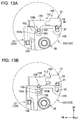
- FIG. 13 are enlarged side views corresponding to the part A of FIG. 3 , illustrating the operations in the second embodiment
- FIG. 14 is an enlarged side view corresponding to the part A of FIG. 3 , illustrating operations in a third embodiment
- FIG. 15 are enlarged side views corresponding to the part A of FIG. 3 , illustrating the operations in the third embodiment.
- FIG. 16 is an enlarged sectional view of a main body unit according to another configuration of the present invention.
- FIGS. 1 and 2 are sectional views of the thermal printer.
- FIG. 1 illustrates a state in which an open-close door is closed
- FIG. 2 illustrates a state in which the open-close door is opened.
- symbols FR, LH, and UP indicate front, left, and upper sides, respectively.
- a thermal printer 1 is a so-called clamshell printer in which printing is performed on a sheet material or recording sheet P drawn out of a paper roll R, and then this recording sheet P is appropriately cut to thereby be used as a ticket, receipt, or the like. That is, the thermal printer 1 mainly includes a casing 2 , an open-close door 6 provided openable and closable with respect to the casing 2 , a main body unit 3 incorporated into the casing 2 , and a detachable unit 4 assembled to the open-close door 6 .
- the casing 2 is molded of a plastic or metal material, and is formed into a box shape having an inlet (opening) 2 a on its upper portion. Inside the casing 2 , there is provided a placing base 2 b for placing thereon the paper roll R dropped in through the inlet 2 a .
- the placing base 2 b is formed to be curved in an arc-shaped manner, and the cylindrical paper roll R can be placed on the placing base 2 b stably.
- the open-close door 6 On the upper surface of the casing 2 , the open-close door 6 is attached and fixed to be openable and closable through the intermediation of a hinge portion 5 .
- the open-close door 6 turns within a range of constant angle in between a closed state illustrated in FIG. 1 and an opened state illustrated in FIG. 2 .
- the inlet 2 a appears when the open-close door 6 is opened, and thus the paper roll R can be dropped into the casing 2 , or taken out of the casing 2 .
- design is made such that a slight gap is provided between the forward end of the open-close door 6 and the casing 2 when the open-close door 6 is closed. Then, with use of this gap, the recording sheet P is drawn out from the inside of the casing 2 .
- this gap functions as a delivery port 2 c of the recording sheet P (see FIG. 1 ).
- a feeding paper cover 2 d protruding to the inner side (rear side) of the casing 2 and extending to the vicinity of the front end portion of the main body unit 3 .
- the printed recording sheet P passes over the feeding paper cover 2 d toward the delivery port 2 c.
- FIG. 3 is a perspective view illustrating a state in which the main body unit and the detachable unit are mounted to each other
- FIG. 4 is an exploded perspective view illustrating a state in which the main body unit and the detachable unit are dismounted to each other
- FIG. 5 is an enlarged side view of a part A of FIG. 3
- FIG. 6 is a sectional view taken along the line B-B of FIG. 3
- FIG. 7 is a plan view of a cutter mechanism. Note that, for convenience of description, the above-mentioned casing 2 and the open-close door 6 are omitted in FIGS. 3 to 6 .
- the detachable unit 4 is assembled to the front inner surface of the open-close door 6 .
- the detachable unit 4 moves together with the open-close door 6 , and can be detachably mounted to the main body unit 3 .
- the detachable unit 4 mainly includes a fixed blade (second blade) 11 , a thermal head 10 (see FIG. 2 ), a head support frame 17 fixing the thermal head 10 , a fixed blade frame (second blade frame) 12 holding the head support frame 17 and the fixed blade 11 , and an attachment frame 13 supporting the fixed blade frame 12 and fixing the detachable unit 4 to the open-close door 6 .
- the attachment frame 13 is a U-shaped plate, which is made of metal or the like and is formed such that its both sides in a lateral direction of the recording sheet P are bent downward.
- the upper surface of the attachment frame 13 is attached to the inner surface of the open-close door 6 while facing the inner surface thereof.
- a pair of cutouts 15 (see FIG. 4 ) extending from the front to rear side of the attachment frame 13 is formed in front end edges of both side surfaces 14 of the attachment frame 13 .
- a pair of L-shaped cutouts 16 extending from the lower peripheral edges of the attachment frame 13 in a height direction is formed in the center portions of the both side surfaces of the attachment frame. Further, the fixed blade frame 12 to which the head support frame 17 and the fixed blade 11 are incorporated is held inside the attachment frame 13 .
- the fixed blade frame 12 is a plate, which is made of metal or the like and is formed such that its both sides in the lateral direction of the recording sheet P are bent downward.
- the fixed blade frame 12 has a length in a longitudinal direction (conveying direction of recording sheet P) larger than that of the attachment frame 13 , and is held in the attachment frame 13 in a state of protruding from the front end of the attachment frame 13 .
- engagement pins 19 and 20 protruding along the lateral directions are formed at center portions and rear end portions of both side surfaces 18 of the fixed blade frame 12 . Those engagement pins 19 and 20 are engaged with the above-mentioned cutouts 15 and 16 , respectively.
- the attachment frame 13 and the fixed blade frame 12 are incorporated with each other.
- the engagement pins 19 and 20 can slide in the cutouts 15 and 16 along the conveying direction (longitudinal direction) of the recording sheet P. That is, even if an assembly position between the detachable unit 4 and the main body unit 3 is slightly misaligned in the longitudinal direction when the open-close door 6 is closed, a slide mechanism between the attachment frame 13 and the fixed blade frame 12 absorbs this misalignment, and hence it is possible to reliably assemble the detachable unit 4 to the main body unit 3 .
- auxiliary shaft 21 is inserted through the through holes.
- the auxiliary shaft 21 functions as a stopper for stopping sliding movement of the fixed blade frame 12 with respect to the attachment frame 13 .
- the auxiliary shaft 21 comes into contact with the peripheral edges of the through holes, to thereby regulate further sliding.
- the auxiliary shaft 21 serves as a rotation fulcrum of the head support frame 17 .
- the thermal head (print head) 10 is supported on the inner side of the center portion in the longitudinal direction of the fixed blade frame 12 through the intermediation of the head support frame 17 , and can operate while using the auxiliary shaft 21 as the rotation fulcrum as described above.
- the thermal head 10 is formed so as to extend in the width direction (lateral direction) of the recording sheet P, and a large number of heating elements (not shown) are aligned on the surface (lower surface) of the thermal head along the lateral direction. Further, the thermal head 10 is arranged at a position of being opposed to an outer peripheral surface of a platen roller 30 described below when the open-close door 6 is closed.
- the lower surface of the thermal head 10 serves as a passing surface for the recording sheet P, and the recording sheet P is conveyed while its print surface is directed upward (while the recording sheet P is opposed to the thermal head 10 ). With this, the recording sheet P is discharged from the delivery port 2 c of the casing 2 while its print surface is directed upward, and hence a user can instantly recognize characters and figures printed on the recording sheet P.
- the thermal head 10 is biased toward the platen roller 30 (downward) by a biasing means 22 (see FIG. 2 ) such as a coil spring provided between the back surface (upper surface) of the head support frame 17 and the lower surface of the fixed blade frame 12 . With this, it is possible to reliably press the thermal head 10 against the recording sheet P sent out by the platen roller 30 , and thus satisfactory printing is possible.
- a biasing means 22 such as a coil spring provided between the back surface (upper surface) of the head support frame 17 and the lower surface of the fixed blade frame 12 .
- the fixed blade 11 is supported on the forward end side of the fixed blade frame 12 .
- the fixed blade 11 has a plate shape extending along the width direction of the recording sheet P (see FIG. 7 ), and is arranged adjacently on the front side of the thermal head 10 (downstream side in conveying direction of recording sheet P).
- the fixed blade 11 is fixed on a front surface side of a fixed blade holder 23 arranged between the thermal head 10 and the fixed blade 11 while a cutting edge 11 a is directed downward. That is, the fixed blade 11 is fixed such that the cutting edge 11 a is opposed to a surface on which printing is performed of the recording sheet P when the open-close door 6 is closed.
- the fixed blade 11 is fixed while being slightly inclined forward from its blade root toward the cutting edge 11 a.
- the fixed blade holder 23 is a plate-shaped member made of resin or the like, and has, on its front surface side, an inclined surface 23 a inclined forward from the upper portion toward the lower portion thereof.
- the fixed blade 11 is held on the inclined surface 23 a .
- the fixed blade holder 23 is supported so as to slightly swing with respect to the fixed blade frame 12 while using its upper end portion as a fulcrum, and so as to slide in a horizontal direction along the inner surface of the fixed blade frame 12 .
- the cutting edge 11 a side of the fixed blade 11 fixed to the fixed blade holder 23 can move in the longitudinal direction (conveying direction of recording sheet P).
- a biasing means 24 such as a coil spring is provided on the rear surface side of the fixed blade holder 23 , and thus the fixed blade holder 23 (fixed blade 11 ) is biased so as to be pushed out forward.
- a lever member 26 is turnably attached to the fixed blade frame 12 so as to cover the fixed blade frame 12 from the front end side thereof.
- the lever member 26 is made of metal or the like, and its both right and left sides and front end side are bent downward. Through holes (not shown) are formed in both side surfaces 27 of the lever member 26 and the both side surfaces 18 of the fixed blade frame 12 (see FIG. 4 ), and a guide shaft 28 is inserted through the through holes. Further, while using the guide shaft 28 as a fulcrum, the lever member 26 is turnably supported with respect to the fixed blade frame 12 in a direction orthogonal to the conveying direction of the recording sheet P (vertical direction).
- lock pins 29 respectively protruding from the both side surfaces 27 of the lever member 26 in the lateral direction of the lever member 26 .
- the lock pins 29 are formed to extend parallel to the guide shaft 28 and have a protruding amount smaller than that of the guide shaft 28 protruding from the side surfaces 27 of the lever member 26 . Further, when the lever member 26 turns, the lock pins 29 move along an arc track around the guide shaft 28 .
- a manipulating portion 31 bent obliquely forward is formed at the rear end of the lever member 26 .
- the manipulating portion 31 protrudes from the upper surface of the open-close door 6 .
- the lever member 26 turns rearward by tilting the manipulating portion 31 rearward, and locking by a latch mechanism described below is canceled, to thereby open the open-close door 6 .
- the lever member 26 is biased forward (in a direction in which the open-close door 6 is closed) by a biasing means (not shown).
- lever members 26 may be provided independently on the right and left sides of the guide shaft 28 , respectively.
- FIG. 8 is a sectional view illustrating a state in which the detachable unit in the state of FIG. 6 is dismounted from the printer.
- the main body unit 3 mainly includes the platen roller 30 , a movable blade (first blade) 32 , a movable blade frame (first blade frame) 33 slidably supporting the movable blade 32 , and a main body frame 34 supporting the platen roller 30 , the movable blade 32 , and the movable blade frame 33 .
- the main body frame 34 is a box-shaped member, which is formed of a metal plate, a resin molded article, or the like, and its upper surface 34 a serves as a passing surface for the recording sheet P.
- the recording sheet P is conveyed in a state in which a back surface of the surface on which printing is performed of the recording sheet P faces the upper surface 34 a and the lateral direction of the upper surface 34 a and the width direction of the recording sheet P correspond to each other.
- the platen roller 30 is provided on the front side of the main body frame 34 .
- the platen roller 30 includes a shaft 30 a (see FIG. 2 ) extending along the width direction of the recording sheet P, and a roller main body 30 b which is made of rubber or the like and provided externally on the shaft 30 a . Both ends of the shaft 30 a are rotatably supported to side plates 35 of the main body frame 34 through the intermediation of bearing members 36 . Note that, a gear (not shown) meshing with a gear train mechanism (not shown) is fixed on one end side of the shaft 30 a .
- a driving force from a drive means such as a motor provided to the main body frame 34 is transmitted to the gear through the gear train mechanism, and thus the platen roller 30 can be rotated.
- the roller main body 30 b of the platen roller 30 is exposed from the upper surface of the main body frame 34 .
- the platen roller 30 is arranged under a predetermined pressure (so-called head pressure) by the biasing means 22 such that its outer peripheral surface is held in contact with the above-mentioned thermal head 10 while sandwiching the recording sheet P drawn out of the paper roll R between the thermal head 10 and the platen roller 30 when the open-close door 6 is closed.
- the recording sheet P drawn out of the paper roll R can be sent out to the front side of the casing 2 through the delivery port 2 c.
- the movable blade frame 33 is a plate made of metal or the like, which includes a front wall 37 arranged so as to cover the front surface side of the main body frame 34 , and side walls 38 (see FIG. 4 ) obtained by bending both sides in the width direction of the front wall 37 rearward in a U-shaped manner.
- Fit-engagement portions 45 obtained by cutting corner portions of the side walls 38 are formed in the lower portions of the side walls 38 of the movable blade frame 33 .
- a coupling pin 46 protruding from the side plates 35 of the main body frame 34 are fit-engaged with the fit-engagement portions 45 .
- the movable blade frame 33 is formed to be turnable about the coupling pin 46 with respect to the main body frame 34 .
- the movable blade frame 33 is configured to be turnable in a direction in which the front wall 37 and the front surface of the main body frame 34 are brought close to or separated from each other, that is, in a direction generally orthogonal to the sliding direction of the movable blade 32 (direction along conveying direction of recording sheet P).
- the position at one end of the movable blade frame 33 (position closest to main body frame 34 : see FIGS. 1 , 3 , 5 , and 6 ) is a home position of the movable blade frame 33
- the position at the other end of the movable blade frame 33 (position farthest from main body frame 34 : see FIGS. 2 and 4 ) is a separated position of the movable blade frame 33
- a biasing means 47 (see FIG. 1 ) such as a coil spring for biasing the movable blade frame 33 to the separated position is provided between the movable blade frame 33 and the main body frame 34 .
- the front wall 37 of the movable blade frame 33 is tilted to the inner side (front side) with respect to the feeding paper cover 2 d of the casing 2 .
- the movable blade 32 comes into contact with the inner surface of the feeding paper cover 2 d of the casing 2 , and hence the movable blade 32 cannot protrude from the movable blade frame 33 .
- the inner surface side of the feeding paper cover 2 d functions as a stopper for preventing protruding of the movable blade 32 , and can prevent protruding of the movable blade 32 from the movable blade frame 33 at the separated position of the movable blade frame 33 . Therefore, ease of maintenance is improved, and a burden on a user can be alleviated. Further, a user cannot access the movable blade 32 directly, and hence safety is ensured.
- the movable blade 32 capable of sliding along a surface direction (vertical direction) of the front wall 37 of the movable blade frame 33 is provided between the front surface of the main body frame 34 and the front wall 37 of the movable blade frame 33 .
- the movable blade 32 constitutes the cutter mechanism (cutter) in cooperation with the above-mentioned fixed blade 11 .
- the movable blade 32 is a plate-shaped blade having a substantially V-shape in plan view, and is formed such that its length from a blade root to a cutting edge 32 a is gradually decreased from the both ends toward the center thereof (such that the movable blade 32 is separated from the fixed blade 11 ).
- the movable blade 32 is held by a movable blade holder 40 and slidably supported so as to be substantially orthogonal to the surface on which printing is performed of the recording sheet P.
- introducing portions 32 b formed to protrude from the cutting edge 32 a and extending parallel to the surface direction of the movable blade 32 .
- the movable blade 32 is held in a state in which the introducing portions 32 b climb onto the both end portions of the cutting edge 11 a of the fixed blade 11 (see FIGS. 7 and 11C ). Therefore, when the movable blade 32 slides with respect to the fixed blade 11 , the fixed blade 11 is pushed rearward by the movable blade 32 .
- the fixed blade 11 is biased forward by the biasing means 24 , and hence the both blades 11 and 32 are held in contact with each other at a moderate contact pressure.
- the cutting edge 32 a of the movable blade 32 and the cutting edge 11 a of the fixed blade 11 are held in not surface-contact but point-contact with each other at two points. Then, as the movable blade 32 slides, the two point-contact points gradually move from the both ends of the movable blade 32 toward the center thereof. Therefore, it is possible to cut the recording sheet P finely.
- the movable blade holder 40 is a plate-shaped member made of resin or the like, and is slidably supported on a guide (not shown) formed in the vertical direction of the movable blade frame 33 . Further, the movable blade holder 40 holds the both sides in the lateral direction and the lower portion of the movable blade 32 . With this, the movable blade 32 can slide in a direction substantially orthogonal to the surface on which printing is performed of the recording sheet P (vertical direction).
- a biasing means such as a coil spring is provided between the movable blade holder 40 and the movable blade frame 33 , and biases the movable blade holder 40 in a direction in which the movable blade holder 40 (movable blade 32 ) is separated from the cutting edge 11 a of the fixed blade 11 , that is, in a direction in which the movable blade 32 retreats into the movable blade frame 33 .
- a rack 41 (see FIG. 6 ) is formed on one side portion or both side portions of the movable blade holder 40 along the vertical direction of the movable blade holder 40 .
- a drive means 42 such as a motor provided on the rear portion side of the main body frame 34 , and a gear train mechanism 44 (see FIG. 6 ) meshing with a drive gear 43 coupled to a shaft 42 a of the drive means 42 , for transmitting a drive force from the drive means 42 to the rack 41 .
- the gear train mechanism 44 includes a first gear 44 a , a second gear 44 b , and a third gear 44 c for moving the rack 41 along the vertical direction of the movable blade frame 33 .
- Those gears 44 a , 44 b , and 44 c are rotatably provided to one of the side plates 35 of the main body frame 34 . Further, when the drive gear 43 rotates owing to driving of the drive means 42 at the home position of the movable blade frame 33 , the drive force is transmitted to the rack 41 through the gears 44 a , 44 b , and 44 c , and thus the movable blade holder 40 slides in the vertical direction.
- the main body unit 3 is provided with a control substrate (not shown) on which various electronic devices are mounted.
- the control substrate outputs electric signals and control signals to the thermal head 10 , or outputs control signals to a drive means (drive means 42 , for example) for driving the platen roller 30 and the movable blade 32 , to thereby control respective components comprehensively.
- the detachable unit 4 is configured to be detachable with respect to the main body unit 3 (movable blade frame 33 and main body frame 34 ) by a ratchet mechanism.
- the both side plates 35 of the main body frame 34 protrude from the upper surface 34 a of the main body frame 34 along the vertical direction, and a pair of a first recess 50 and a second recess 51 obtained by cutting each of the side plates 35 in the height direction is formed at the front upper end edge of each of the side plates 35 .
- the first recesses 50 receives and holds the guide shaft 28 of the above-mentioned lever member 26 .
- the first recess 50 has, at its inner peripheral edge, a first inclined portion 50 a obtained by cutting the side plate 35 from the upper end edge thereof obliquely forward, a first guide portion 50 b obtained by cutting the side plate 35 from the forward end of the first inclined portion 50 a downward, a receiving portion 50 c obtained by cutting the side plate 35 from the forward end of the first guide portion 50 b rearward, for receiving the guide shaft 28 , a second inclined portion 50 d formed to extend from the receiving portion 50 c obliquely forward, and a second guide portion 50 e extending from the forward end of the second inclined portion 50 d upward and having a length smaller than that of the first guide portion 50 b .
- a regulating portion (first regulating portion) 50 f for regulating upward movement of the guide shaft 28 held in the receiving portion 50 c is formed at the boundary between the receiving portion 50 c and the first guide
- Each of the second recesses 51 is formed so as to be continuous obliquely forward with each of the first recesses 50 , and receives and holds each of the lock pins 29 of the above-mentioned lever member 26 .
- Each of the second recesses 51 has a receiving portion 51 a obtained by cutting the side plate 35 obliquely forward from the forward end of the second guide portion 50 e of each of the first recesses 50 , for receiving each of the lock pins 29 , a first inclined portion (guide portion) 51 b formed to extend from the receiving portion 51 a obliquely rearward, and a second inclined portion 51 c formed to extend obliquely upward from the forward end of the first inclined portion 51 b up to the upper end edge of the side plate 35 .
- the first inclined portion 51 b of each of the second recesses 51 is formed to be larger than a track (arc radius) of the lock pins 29 turning about the guide shaft 28 .
- a regulating portion (second regulating portion) 51 d for regulating upward movement of the lock pin 29 and for guiding the lock pin 29 to escape from the receiving portion 51 a when the lever member 26 turns about the guide shaft 28 .
- a distance in the longitudinal direction between the first inclined portion 50 a of the first recess 50 and the regulating portion 51 d of the second recess 51 is smaller than a distance in the longitudinal direction between the guide shaft 28 and each of the lock pins 29 .
- a pair of extending portions 53 (see FIG. 5 ) having a triangular shape in plan view and extending so as to be inclined upward to the rear is formed at the upper rear end edges of the both side walls 38 of the movable blade frame 33 .
- third recesses 54 are formed at the forward end portions of the extending portions 53 to be engaged with the above-mentioned guide shaft 28 at the home position of the movable blade frame 33 .
- the third recesses 54 are formed so as to overlap the first recesses 50 in the width direction of the recording sheet P at the home position of the movable blade frame 33 .
- each of the third recesses 54 has a guide portion 54 a obtained by cutting each of the extending portions 53 from the upper end edge thereof obliquely forward, a receiving portion 54 b formed at the forward end of the guide portion 54 a , for receiving the guide shaft 28 , and a hook portion 54 c formed at the forward end of the receiving portion 54 b and extending parallel to the inclined surface of the guide portion 54 a.
- the guide shaft 28 and the lock pins 29 formed in the detachable unit 4 and the first to third recesses 50 , 51 , and 54 formed in the main body unit 3 constitute the ratchet mechanism for detachably mounting the detachable unit 4 to the main body unit 3 .
- the detachable unit 4 is configured to be detachable from a mounted position (see FIGS. 1 , 3 , 5 , and 6 ) in which the guide shaft 28 and the lock pins 29 are held in the first to third recesses 50 , 51 , and 54 and mounted to the main body unit 3 to a dismounted position (see FIGS.
- the detachable unit 4 is configured to be turnable in the direction in which the movable blade 32 slides in accordance with open-close operation of the open-close door 6 (direction orthogonal to surface on which printing is performed of recording sheet P).
- the above-mentioned guide portion 54 a of each of the third recesses 54 guides the guide shaft 28 such that the movable blade frame 33 moves to the home position when the detachable unit 4 moves to the mounted position, and guides the guide shaft 28 such that the movable blade frame 33 moves to the separated position when the detachable unit 4 moves to the dismounted position. Note that, detailed description of specific operation of the ratchet mechanism is made later.
- the detachable unit 4 turns from the mounted position to the dismounted position along the sliding direction of the movable blade 32 .
- the movable blade frame 33 turns from the home position to the separated position in the direction orthogonal to the sliding direction of the movable blade 32 . That is, the detachable unit 4 is engaged with both the movable blade frame 33 and the main body frame 34 by the ratchet mechanism in the state at the mounted position, and engagement between the movable blade frame 33 and the main body frame 34 is released at the dismounted position. Therefore, in conjunction with turning operation of the detachable unit 4 , locking between the main body frame 34 and the movable blade frame 33 is canceled, and thus the movable blade frame 33 turns.
- fourth recesses 55 obtained by cutting the side plates 35 from the upper end edges thereof in the vertical direction.
- the fourth recesses 55 receive the above-mentioned auxiliary shaft 21 inserted through the fixed blade frame 12 , to thereby position the detachable unit 4 with respect to the main body unit 3 .
- the paper roll R is dropped into the casing 2 through the inlet 2 a in a state in which the open-close door 6 is opened.
- the recording sheet P is drawn out to the outside of the casing 2 by a certain length in advance.
- the open-close door 6 is closed, and the open-close door 6 is locked by the above-mentioned ratchet mechanism.
- the recording sheet P is sandwiched between the platen roller 30 and the thermal head 10 , and enters the state of being drawn out to the outside of the casing 2 from the delivery port 2 c.
- FIGS. 9 and 10 are explanation views illustrating operations in this embodiment.
- FIG. 9 are enlarged side views corresponding to the part A of FIG. 3
- FIG. 10 are enlarged sectional views.
- FIG. 11 are explanation views illustrating an arrangement relation in the cutter mechanism which varies in accordance with operation of the open-close door from an opened state of the open-close door ( FIG. 11A ) to a closed state ( FIG. 11C ).
- the detachable unit 4 In order to mount the detachable unit 4 to the main body unit 3 , the detachable unit 4 is pushed downward through the intermediation of the open-close door 6 . Then, the outer peripheral surface of the guide shaft 28 supporting the lever member 26 comes into contact with the first inclined portions 50 a of the first recesses 50 , and the guide shaft 28 slips off the first inclined portions 50 a.
- each distance in the longitudinal direction between the first inclined portions 50 a of the first recesses 50 and the regulating portions 51 d of the second recesses 51 is smaller than a distance in the longitudinal direction between the guide shaft 28 and each of the lock pins 29 , and hence the outer peripheral surface of the guide shaft 28 is held in contact with the first inclined portions 50 a of the first recesses 50 , and the outer peripheral surfaces of the lock pins 29 are held in contact with the second inclined portions 51 c of the second recess 51 .
- the cutting edges 32 a and 11 a of the movable blade 32 and the fixed blade 11 are gradually brought close to each other.
- the guide shaft 28 slips off the first guide portions 50 b of the first recesses 50 , the outer peripheral surface of the guide shaft 28 comes into contact with the upper portions of the guide portions 54 a of the third recesses 54 formed in the movable blade frame 33 . Then, when the detachable unit 4 is further pushed downward, the guide shaft 28 slips off the first guide portions 50 b of the first recesses 50 and the guide portions 54 a of the third recesses 54 . In this case, in the detachable unit 4 , the guide shaft 28 and the lock pins 29 are held in the first recesses 50 and the second recesses 51 , and hence the detachable unit 4 is regulated in its movement in the longitudinal direction.
- the movable blade frame 33 moves relatively in a direction of being brought close to the front surface of the main body frame 34 . That is, the pushing force to push down the detachable unit 4 acts on the guide portions 54 a of the third recesses 54 through the guide shaft 28 . As a result, the guide shaft 28 slips off the guide portions 54 a of the third recesses 54 , and the movable blade frame 33 is pulled toward the main body unit 3 .
- the lock pins 29 pass over the second inclined portions 51 c of the second recesses 51 and slip off the first inclined portions 51 b .
- the lever member 26 is biased forward by a biasing means (not shown), and hence the lock pins 29 turn (return) along the arc track about the guide shaft 28 in accordance with turning of the lever member 26 .
- the lock pins 29 slip off while sliding on the first inclined portions 51 b of the second recesses 51 .
- the guide shaft 28 passes over the first guide portions 50 b of the first recesses 50 and the guide portions 54 a of the third recesses 54 , the guide shaft 28 is received in the receiving portions 50 c and 54 b of the first recesses 50 and the third recesses 54 .
- the lock pins 29 slip off the first inclined portions 51 b of the second recesses 51 , and the lock pins 29 are received in the receiving portions 51 a of the second recesses 51 .
- the detachable unit 4 enters the state at the mounted position of being mounted to the main body unit 3
- the movable blade frame 33 enters the state at the home position of being incorporated with the main body frame 34 .
- the detachable unit 4 is locked by the main body unit 3 , and the open-close door 6 is closed (see FIGS. 5 and 10A ).
- the rack 41 of the movable blade holder 40 is meshed with the third gear 44 c of the main body frame 34 , and the introducing portions 32 b of the movable blade 32 are held while climbing onto the both ends of the cutting edge 11 a of the fixed blade 11 (see FIGS. 7 and 11C ).
- the introducing portions 32 b of the movable blade 32 are arranged so as to climb onto the cutting edge 11 a of the fixed blade 11 .
- the both blades 32 and 11 are held in contact with each other at a moderate contact pressure without forming bends for guiding in the introducing portions as in a conventional case. Therefore, it is possible to reduce manufacturing cost for forming bends.
- the auxiliary shaft 21 is also received in the fourth recesses 55 , and hence the detachable unit 4 and the main body unit 3 are fixed to each other at two points in the longitudinal direction, that is, at the ratchet mechanism and at the auxiliary shaft 21 and the fourth recesses 55 . With this, it is possible to stably hold the detachable unit 4 with respect to the main body unit 3 without backlash.
- the movable blade frame 33 is biased toward the separated position by the biasing means 47 (see FIG. 1 ), and hence this biasing force acts on the guide shaft 28 through the receiving portions 54 b of the third recesses 54 so as to push the guide shaft 28 forward.
- the outer peripheral surface of the guide shaft 28 comes into contact with the second guide portions 50 e of the first recesses 50 , and the outer peripheral surfaces of the lock pins 29 are pressed against the inner peripheral surfaces of the receiving portions 51 a of the second recesses 51 while being held in contact therewith. Therefore, it is possible to prevent backlash in the longitudinal direction at the mounted position of the detachable unit 4 .
- the upper outer peripheral surface of the guide shaft 28 is engaged with the regulating portions 50 f of the first recesses 50 and the hook portions 54 c of the third recesses 54 , and the lock pins 29 are engaged with the regulating portions 51 d of the second recesses 51 .
- the drive means is operated by the control substrate, and the platen roller 30 is rotated.
- the recording sheet P sandwiched between the outer peripheral surface of the platen roller 30 and the thermal head 10 is sent out to the front of the casing 2 , and the paper roll R placed on the placing base 2 b rotates.
- the thermal head 10 is operated via the control substrate. With this, a large number of heating elements generate heat appropriately. Thus, it is possible to clearly print various characters, figures, and the like on the sent-out recording sheet P.
- the recording sheet P which is further sent out by the platen roller 30 , passes through between the cutting edges 11 a and 32 a of the fixed blade 11 and the movable blade 32 . Then, when the drive means 42 is operated and the movable blade 32 is slid upward, the cutting edge 32 a of the movable blade 32 climbs onto the fixed blade 11 from the both sides in the width direction of the fixed blade 11 , and the recording sheet P is sandwiched between the both blades 32 and 11 in a state in which a moderate contact pressure is imparted to the fixed blade 11 .
- the recording sheet P onto which the printing is performed is separated from the recording sheet P onto which the printing is not performed, and the recording sheet P wound into the paper roll R can be used as a receipt, ticket, or the like.
- the guide shaft 28 slips out of the receiving portions 50 c of the first recesses 50 to slide over the second inclined portions 50 d obliquely forward, and the guide shaft 28 slips out of the receiving portions 54 b of the third recesses 54 to reach the guide portions 54 a.
- the movable blade frame 33 is biased toward the separated position by the biasing means 47 , and hence this biasing force acts on the guide shaft 28 through the guide portions 54 a of the third recesses 54 so as to push the guide shaft 28 upward.
- the guide shaft 28 passes over the regulating portions 50 f of the first recesses 50 to be pushed up to the upper sides of the first recesses 50 , and the lock pins 29 slide over the second inclined portions 51 c of the second recesses 51 to be pushed up to the upper sides of the second recesses 51 .
- the detachable unit 4 is released from the main body unit 3 owing to releasing of the ratchet mechanism. Further, the detachable unit 4 moves to the dismounted position, and the movable blade frame 33 moves to the separated position, to thereby release meshing between the rack 41 of the movable blade holder 40 and the third gear 44 c.
- the detachable unit 4 turns in a direction orthogonal to the surface on which printing is performed of the recording sheet P, that is, in the sliding direction of the movable blade 32 . Therefore, as illustrated in FIGS. 11C to 11A , the track of the cutting edge 11 a of the fixed blade 11 held in the detachable unit 4 extends along the substantially vertical direction.
- the movable blade frame 33 turns about the coupling pin 46 in the conveying direction of the recording sheet P, that is, in a direction orthogonal to the sliding direction of the movable blade 32 . Therefore, as illustrated in FIGS. 11C to 11A , similarly to the turning direction of the movable blade frame 33 , the cutting edge 32 a of the movable blade 32 held in the movable blade frame 33 exhibits a track inclined forward and downward.
- the movable blade frame 33 turns in a direction orthogonal to the sliding direction of the movable blade 32 .
- the movable blade 32 and the fixed blade 11 retreat in directions orthogonal to each other, respectively, and hence the contact pressure between both blades 32 and 11 is promptly released at the time of turning of the detachable unit 4 and the movable blade frame 33 .
- the movable blade 32 and the fixed blade 11 retreat in directions orthogonal to each other, respectively.
- the both blades 32 and 11 neither interfere with each other due to contact therebetween nor retreat while catching the recording sheet P therebetween.
- the movable blade frame 33 and the detachable unit 4 are easily moved to the separated position and the dismounted position, respectively, and thus it is possible to promptly release bite between the both blades 32 and 11 .
- the movable blade frame 33 is biased toward the separated position by the biasing means 47 (see FIG. 1 ).
- the biasing means 47 see FIG. 1 .
- the detachable unit 4 in a state in which movement of the guide shaft 28 and the lock pins 29 is regulated at the mounted position by the regulating portions 50 f of the first recesses 50 and the regulating portions 51 d of the second recesses 51 , respectively, the detachable unit 4 is mounted to the main body frame 34 .
- the lock pins 29 are guided by the first inclined portions 51 b to slip out of the second recesses 51 . With this, locking between the detachable unit 4 and the main body frame 34 is canceled, and thus it is possible to easily detach the detachable unit 4 from the main body frame 34 .
- the guide shaft 28 provided in the detachable unit 4 is engaged with the third recesses 54 of the movable blade frame 33 , and hence it is possible to stably hold the detachable unit 4 to the main body unit 3 .
- the movable blade frame 33 is biased toward the separated position by the biasing means 47 , positioning between the detachable unit 4 and the movable blade frame 33 is reliably performed as described above.
- the movable blade 32 with respect to the fixed blade 11 at an appropriate position. That is, the movable blade 32 can be held in press-contact with the fixed blade 11 at a moderate contact pressure.
- the thermal printer 1 of this embodiment even when there arises a problem that the movable blade 32 is stopped during sliding due to paper jam or the like, it is possible to easily restore the movable blade 32 to the state before the problem arises. Further, positioning between the movable blade frame 33 and the detachable unit 4 is reliably performed, and it is possible to improve printing accuracy and cutting accuracy.
- FIG. 12 is an enlarged side view corresponding to the part A of FIG. 3 in the second embodiment.
- the second embodiment differs from the above-mentioned first embodiment in that a movable blade frame is biased toward the home position, and in a configuration of a ratchet mechanism constituted by a detachable unit and a main body unit. Note that, in the following description, the same components as those in the first embodiment are denoted by the same reference symbols.
- a pair of engagement pins 128 is formed on front portions of both side surfaces 118 of a fixed blade frame 112 of a detachable unit 104 of this embodiment.
- the engagement pins 128 protrude from the both side surfaces 118 in the lateral directions in the front of the auxiliary shaft 21 .
- a pair of recesses 150 is formed in upper peripheral edges of both side plates 135 of a main body frame 134 of a main body unit 103 .
- the recesses 150 receive the above-mentioned engagement pins 128 at the time of mounting of the detachable unit 104 , and are formed by cutting the both side plates 135 from the upper peripheral edges thereof downward.
- a pair of hook portions 153 having a triangular shape in plan view and extending rearward is formed at upper rear end edges of both side walls 138 of a movable blade frame 133 .
- the hook portions 153 are engaged with the engagement pins 128 received in the recesses 150 .
- Each of the hook portions 153 includes a stopper portion 153 a formed on its lower edge side and extending horizontally in the longitudinal direction, and a guide portion 153 b formed on its upper edge side and inclined upward and forward.
- the movable blade frame 133 is provided with a manipulating lever (not shown). Through manipulating the manipulating lever, the movable blade frame 133 is turned from the home position to the separated position. Further, between the movable blade frame 133 and the main body frame 134 , there is provided a biasing means such as a coil spring for biasing the movable blade frame 133 to the home position, that is, for biasing the same in a direction in which the movable blade frame 133 is brought close to the main body frame 134 . Then, the engagement pins 128 , the recesses 150 , and the hook portions 153 constitute a ratchet mechanism of this embodiment.
- a manipulating lever Through manipulating the manipulating lever, the movable blade frame 133 is turned from the home position to the separated position. Further, between the movable blade frame 133 and the main body frame 134 , there is provided a biasing means such as a coil spring for biasing the movable blade frame 133 to the home position, that is,
- the engagement pins 128 provided to the detachable unit 104 are engaged with the recesses 150 and the hook portions 153 while being sandwiched therebetween.
- FIGS. 13A and 13B are explanatory views illustrating the operations in the second embodiment.
- the detachable unit 104 is lifted upward, that it, lifted up along the sliding direction of the movable blade 32 . Then, when the detachable unit 104 is lifted upward, the engagement pins 128 are lifted upward in the recesses 150 , and pass over boundaries between the stopper portions 153 a and the guide portions 153 b.
- the movable blade frame 133 moves to the separated position furthest to the main body frame 134 , and meshing between the rack 41 of the movable blade holder 40 (see FIG. 6 ) and the third gear 44 c (see FIG. 6 ) is released. With this, the movable blade 32 is biased by the biasing means, and retreats to the initial position in the movable blade frame 133 .
- the movable blade frame 133 is restored to the home position owing to a biasing force of the biasing means.
- the engagement pins 128 which has passed over the boundaries between the stopper portions 153 a and the guide portions 153 b , slide over the guide portions 153 b of the hook portions 153 to be lifted upward. That is, the biasing force to restore the movable blade frame 133 to the home position acts on the engagement pins 128 through the guide portions 153 b .
- the guide portions 153 b lift up the engagement pins 128 so as to push out the same as the movable blade frame 133 is restored.
- the ratchet mechanism is released by lifting up the engagement pins 128 to the upper end portions of the guide portions 153 b , and locking between the detachable unit 104 and the main body unit 103 is canceled. Then, by opening the open-close door 6 (see FIG. 1 ), the detachable unit 104 is separated from the main body unit 103 with a large space therebetween. Thus, it is possible to remove the recording sheet P caught between the movable blade 32 and the fixed blade 11 .
- the detachable unit 104 turns along the sliding direction of the movable blade 32 , whereas the movable blade frame 133 turns in a direction orthogonal to the sliding direction of the movable blade 32 .
- the movable blade 32 and the fixed blade 11 retreat in directions orthogonal to each other, respectively, and hence the both blades 32 and 11 do not interfere with each other due to contact therebetween at the time of retreating.
- the manipulating lever is provided to the movable blade frame 133 .
- the manipulating lever is provided to the fixed blade frame 112 side and the movable blade frame 133 is turned in a direction orthogonal to the sliding direction of the movable blade 32 in conjunction with manipulation of the manipulating lever.
- FIG. 14 is an enlarged side view corresponding to the part A of FIG. 3 in the third embodiment.
- the third embodiment differs from the above-mentioned second embodiment in a configuration of a ratchet mechanism constituted by a detachable unit and a main body unit. Note that, in the following description, the same components as those in each of the first and second embodiments are denoted by the same reference symbols.
- a pair of engagement pins 255 is formed on upper portions of both side plates 235 of a main body frame 234 of a main body unit 203 .
- the engagement pins 255 protrude in the lateral directions from the upper peripheral edges at the center portions in the longitudinal direction of the side plates 235 .
- a pair of hook portions 253 having a triangular shape in plan view and extending rearward is formed at upper rear end edges of both side walls 238 of a movable blade frame 233 .
- the hook portions 253 are engaged in the recesses 150 with the engagement pins 128 received in the recesses 150 , and formed to be gradually narrowed rearward. That is, the hook portions 253 are engaged in the recesses 150 with the engagement pins 128 received in the recesses 150 , and each of the hook portions 253 includes a first inclined portion 253 a formed at its lower peripheral edge to be inclined rearward and upward, and a second inclined portion 253 b formed at its upper peripheral edge to be inclined rearward and downward.
- a biasing means such as a coil spring for biasing the movable blade frame 233 to the home position, that is, for biasing the same in a direction in which the movable blade frame 233 is brought close to the main body frame 234 .
- a lever member 210 capable of turning with respect to the frame 13 is provided to the frame 13 of the detachable unit 204 .
- the lever member 210 mainly includes a manipulating portion 211 , extending portions 212 , and engagement portions 213 .
- the manipulating portion 211 is a plate-shaped member extending in the lateral direction of the frame 13 , and is arranged while being inclined forward and upward. A pair of the extending portions 212 extending downward is formed at the both ends of the manipulating portion 211 .
- a turning pin 215 is inserted through the extending portions 212 from the center portion in the longitudinal direction (vertical direction) of each of the extending portions 212 to the thickness direction (lateral direction) thereof.
- the turning pin 215 couples the lever member 210 and the side surfaces 14 of the frame 13 to each other so as to turnably support the lever member 210 . Through manipulating the manipulating portion 211 , the lever member 210 can turn about the turning pin 215 along the conveying direction of the recording sheet P.
- the engagement portions 213 bent rearward from the extending portions 212 by approximately 90 degrees are formed at the lower ends of the extending portions 212 , respectively.
- the engagement portions 213 are engaged with the above-mentioned engagement pins 255 , to thereby lock the detachable unit 204 and the main body unit 203 with each other.
- a biasing means (not shown) is provided to the lever member 210 , and biases the engagement portions 213 rearward.
- the lever member 210 and the engagement pins 255 , and the hook portions 253 and the engagement pins 128 constitute a ratchet mechanism of this embodiment.
- FIGS. 15A-15B are explanatory views illustrating the operations in the third embodiment.
- the movable blade frame 233 moves to the separated position furthest to the main body frame 234 , and meshing between the rack 41 of the movable blade holder 40 (see FIG. 6 ) and the third gear 44 c (see FIG. 6 ) is released. With this, the movable blade 32 is biased by the biasing means, and retreats to the initial position in the movable blade frame 233 .
- the movable blade frame 233 is restored to the home position owing to a biasing force of the biasing means.
- the engagement pins 128 slide over the second inclined portions 253 b of the hook portions 253 to be lifted upward. That is, as illustrated in FIG. 15B , the biasing force to restore the movable blade frame 233 to the home position acts on the engagement pins 128 through the second inclined portions 253 b .
- the second inclined portions 253 b lift up the engagement pins 128 so as to push out the same as the movable blade frame 233 is restored.
- the ratchet mechanism is released by lifting up the engagement pins 128 to the upper end portions of the second inclined portions 253 b , the contact pressure between the both blades 32 and 11 is released, and locking between the detachable unit 204 and the main body unit 203 is canceled. Further, by lifting the manipulating portion 211 upward in this state, the open-close door 6 (see FIG. 1 ) is opened, and the detachable unit 204 is separated from the main body unit 203 with a large space therebetween. Thus, it is possible to remove the recording sheet P caught between the movable blade 32 and the fixed blade 11 .
- the manipulating portion 211 is provided to the detachable unit 204 side. Therefore, by lifting the manipulating portion 211 upward while being pulled down, it is possible to simultaneously perform separating operation of the both blades 32 and 11 from each other, releasing operation of the ratchet mechanism, and opening operation of the open-close door 6 . That is, those operations can be performed in one-time operation, and hence it is possible to improve operativity, and to alleviate a burden on a user.
- the thermal printer 1 is described as the example of the printer with a cutter.
- the present invention is not limited to the thermal printer 1 .
- an ink jet printer having a configuration in which the print head is an ink jet head and printing is performed on the drawn-out recording sheet P with use of ink droplets.
- the drop-in thermal printer in which the paper roll R is dropped to be merely placed on the placing base 2 b .
- a thermal printer of a shaft-supporting type including a shaft-supporting mechanism for rotatably supporting the paper roll R inside the casing 2 .
- FIG. 16 is a sectional view of a main body unit according to another configuration of the present invention. Note that, in the following description, the same components as those in the first embodiment are denoted by the same reference symbols, and description thereof is omitted.
- a paper powder chute 300 is provided along the lateral direction between a main body frame 334 of a main body unit 303 and the movable blade frame 33 .
- the paper powder chute 300 has, in a lower portion of a front surface 334 b of the main body frame 334 (surface opposed to front wall 37 of movable blade frame 33 ), a through hole 301 formed therein to pass through the front surface 334 b in its thickness direction.
- the through hole 301 is inclined downward toward the rear thereof, and has one end opened to the front surface 334 b of the main body frame 334 and the other end opened to a space formed in the lower portion of the main body frame 334 . That is, the through hole 301 functions as a discharge port for the paper powder scattering or accumulating between the movable blade frame 33 and the main body frame 334 .
- a guide plate 302 extending forward from the front surface 334 b of the main body frame 334 .
- the guide plate 302 is a plate-shaped member inclined upward toward the front thereof, and guides to the through hole 301 the paper powder scattering or accumulating between the movable blade frame 33 and the main body frame 334 . Note that, the guide plate 302 extends so as not to interfere with the movable blade 32 and the movable blade holder 40 .
- a paper powder receiving portion (paper powder accumulating portion) 310 opened upward.
- the paper powder receiving portion 310 receives the paper powder guided by the guide plate 302 , and the received paper powder is discharged through the through hole 301 .
- the paper powder chute 300 is provided between the main body frame 334 and the movable blade frame 33 , and hence the paper powder, which is generated when the recording sheet P is cut, is guided by the guide plate 302 to be received in the paper powder receiving portion 310 when falling downward due to impact or the like at the time of cutting operation and open-close operation of the movable blade frame 33 . Then, the paper powder received in the paper powder receiving portion 310 passes through the through hole 301 to be discharged into the space formed in the lower portion of the main body frame 334 . Therefore, the paper powder does not accumulate between the movable blade frame 33 and the main body frame 334 , and hence it is possible to improve ease of maintenance.
- design modifications can be appropriately made on the turning amount of the movable blade frame from the home position to the separated position. For example, by securing a large turning amount of the movable blade frame, a large open space is formed between the main body frame and the movable blade frame when the movable blade frame is at the separated position. Thus, it becomes easy to perform work in the movable blade frame at the time of maintenance and the like.
Landscapes
- Life Sciences & Earth Sciences (AREA)
- Forests & Forestry (AREA)
- Engineering & Computer Science (AREA)
- Mechanical Engineering (AREA)
- Handling Of Sheets (AREA)
Applications Claiming Priority (2)
| Application Number | Priority Date | Filing Date | Title |
|---|---|---|---|
| JP2008-309786 | 2008-12-04 | ||
| JP2008309786A JP5279471B2 (ja) | 2008-12-04 | 2008-12-04 | カッター付きプリンタ |
Publications (2)
| Publication Number | Publication Date |
|---|---|
| US20100143018A1 US20100143018A1 (en) | 2010-06-10 |
| US8469616B2 true US8469616B2 (en) | 2013-06-25 |
Family
ID=41723136
Family Applications (1)
| Application Number | Title | Priority Date | Filing Date |
|---|---|---|---|
| US12/592,863 Expired - Fee Related US8469616B2 (en) | 2008-12-04 | 2009-12-03 | Printer with cutter |
Country Status (3)
| Country | Link |
|---|---|
| US (1) | US8469616B2 (fr) |
| EP (1) | EP2193892A1 (fr) |
| JP (1) | JP5279471B2 (fr) |
Cited By (2)
| Publication number | Priority date | Publication date | Assignee | Title |
|---|---|---|---|---|
| US20200079121A1 (en) * | 2018-09-11 | 2020-03-12 | Seiko Epson Corporation | Printer and cutter device of printer |
| CN110884265A (zh) * | 2018-09-11 | 2020-03-17 | 精工爱普生株式会社 | 打印机以及打印机的剪切器装置 |
Families Citing this family (18)
| Publication number | Priority date | Publication date | Assignee | Title |
|---|---|---|---|---|
| JP5596983B2 (ja) * | 2010-01-08 | 2014-10-01 | セイコーインスツル株式会社 | プリンタ |
| US8585305B2 (en) * | 2010-02-02 | 2013-11-19 | Seiko Instruments Inc. | Printer |
| JP2011168029A (ja) * | 2010-02-22 | 2011-09-01 | Seiko Instruments Inc | プリンタ |
| JP5031075B2 (ja) * | 2010-09-03 | 2012-09-19 | 東芝テック株式会社 | カッター機構及びそれを備えたプリンタ |
| JP5873326B2 (ja) | 2011-12-22 | 2016-03-01 | 富士通コンポーネント株式会社 | プリンタ |
| JP5977619B2 (ja) * | 2012-08-23 | 2016-08-24 | 富士通コンポーネント株式会社 | プリンタ装置 |
| JP6403399B2 (ja) * | 2014-02-28 | 2018-10-10 | 富士通コンポーネント株式会社 | プリンタ装置 |
| JP6507892B2 (ja) * | 2014-08-25 | 2019-05-08 | セイコーエプソン株式会社 | カッター駆動機構、カッターおよびプリンター |
| KR101764246B1 (ko) * | 2015-03-26 | 2017-08-04 | 제이스테판 주식회사 | 커버 개폐방향과 용지 절단방향이 동일한 프린터 |
| JP6520461B2 (ja) * | 2015-06-25 | 2019-05-29 | 株式会社寺岡精工 | 切断機構及び印刷装置 |
| JP6624902B2 (ja) * | 2015-11-20 | 2019-12-25 | セイコーインスツル株式会社 | 印字ユニット及びサーマルプリンタ |
| CN105835544B (zh) * | 2016-03-25 | 2018-03-20 | 励能(深圳)科技有限公司 | 一种厚片型自动切纸的票式打印机 |
| CN106079903B (zh) * | 2016-08-15 | 2017-11-21 | 厦门普瑞特科技有限公司 | 一种快捷装拆的打印机芯 |
| WO2018188254A1 (fr) * | 2017-04-13 | 2018-10-18 | 厦门普瑞特科技有限公司 | Dispositif de puissance anti-brouillage à haut rendement, et imprimante avec fonction de réparation de défaut et pourvue de celui-ci |
| JP6704152B2 (ja) * | 2019-04-24 | 2020-06-03 | 株式会社寺岡精工 | 印刷装置 |
| JP7226871B2 (ja) * | 2020-04-15 | 2023-02-21 | 株式会社寺岡精工 | 印刷装置 |
| JP2023072571A (ja) * | 2021-11-12 | 2023-05-24 | セイコーインスツル株式会社 | カッターユニット及びプリンタ |
| JP7384501B2 (ja) | 2022-02-07 | 2023-11-21 | 株式会社寺岡精工 | 印刷装置 |
Citations (11)
| Publication number | Priority date | Publication date | Assignee | Title |
|---|---|---|---|---|
| US20020056354A1 (en) | 2000-11-10 | 2002-05-16 | Citizen Watch Co., Ltd. | Printer |
| JP2002219832A (ja) | 2000-11-27 | 2002-08-06 | F & F:Kk | プリンタ |
| US6447187B1 (en) | 2000-10-25 | 2002-09-10 | Xac Automation Corporation | Restraining module for a cutter of a printer |
| WO2003064163A1 (fr) | 2002-01-28 | 2003-08-07 | Wincor Nixdorf International Gmbh | Imprimante pour bande de papier continue comprenant un dispositif de decoupe . |
| JP2003311676A (ja) * | 2002-04-30 | 2003-11-05 | F & F:Kk | カッター装置およびプリンタ |
| EP1445113A1 (fr) | 2003-02-05 | 2004-08-11 | Fujitsu Component Limited | Imprimante et coupe-papier |
| US6848847B2 (en) * | 2001-11-16 | 2005-02-01 | Seiko Epson Corporation | Printer unit and printing apparatus incorporating the same |
| US6899479B2 (en) * | 2002-09-12 | 2005-05-31 | Toshiba Tec Kabushiki Kaisha | Printer and commodity information processing apparatus |
| US7267500B2 (en) * | 2004-03-22 | 2007-09-11 | Fujitsu Component Limited | Printer apparatus |
| US7281874B2 (en) * | 2004-10-27 | 2007-10-16 | Fujitsu Component Limited | Thermal printer unit |
| EP1955833A1 (fr) | 2007-02-08 | 2008-08-13 | Seiko Instruments Inc. | Dispositif de découpe de feuille et imprimante |
Family Cites Families (2)
| Publication number | Priority date | Publication date | Assignee | Title |
|---|---|---|---|---|
| JP2517763Y2 (ja) * | 1990-11-08 | 1996-11-20 | セイコーエプソン株式会社 | プリンタ |
| JP4438639B2 (ja) * | 2005-02-10 | 2010-03-24 | セイコーインスツル株式会社 | プリンタ |
-
2008
- 2008-12-04 JP JP2008309786A patent/JP5279471B2/ja not_active Expired - Fee Related
-
2009
- 2009-12-01 EP EP09177623A patent/EP2193892A1/fr not_active Withdrawn
- 2009-12-03 US US12/592,863 patent/US8469616B2/en not_active Expired - Fee Related
Patent Citations (11)
| Publication number | Priority date | Publication date | Assignee | Title |
|---|---|---|---|---|
| US6447187B1 (en) | 2000-10-25 | 2002-09-10 | Xac Automation Corporation | Restraining module for a cutter of a printer |
| US20020056354A1 (en) | 2000-11-10 | 2002-05-16 | Citizen Watch Co., Ltd. | Printer |
| JP2002219832A (ja) | 2000-11-27 | 2002-08-06 | F & F:Kk | プリンタ |
| US6848847B2 (en) * | 2001-11-16 | 2005-02-01 | Seiko Epson Corporation | Printer unit and printing apparatus incorporating the same |
| WO2003064163A1 (fr) | 2002-01-28 | 2003-08-07 | Wincor Nixdorf International Gmbh | Imprimante pour bande de papier continue comprenant un dispositif de decoupe . |
| JP2003311676A (ja) * | 2002-04-30 | 2003-11-05 | F & F:Kk | カッター装置およびプリンタ |
| US6899479B2 (en) * | 2002-09-12 | 2005-05-31 | Toshiba Tec Kabushiki Kaisha | Printer and commodity information processing apparatus |
| EP1445113A1 (fr) | 2003-02-05 | 2004-08-11 | Fujitsu Component Limited | Imprimante et coupe-papier |
| US7267500B2 (en) * | 2004-03-22 | 2007-09-11 | Fujitsu Component Limited | Printer apparatus |
| US7281874B2 (en) * | 2004-10-27 | 2007-10-16 | Fujitsu Component Limited | Thermal printer unit |
| EP1955833A1 (fr) | 2007-02-08 | 2008-08-13 | Seiko Instruments Inc. | Dispositif de découpe de feuille et imprimante |
Cited By (4)
| Publication number | Priority date | Publication date | Assignee | Title |
|---|---|---|---|---|
| US20200079121A1 (en) * | 2018-09-11 | 2020-03-12 | Seiko Epson Corporation | Printer and cutter device of printer |
| CN110884265A (zh) * | 2018-09-11 | 2020-03-17 | 精工爱普生株式会社 | 打印机以及打印机的剪切器装置 |
| US10875327B2 (en) * | 2018-09-11 | 2020-12-29 | Seiko Epson Corporation | Printer and cutter device of printer |
| CN110884265B (zh) * | 2018-09-11 | 2021-03-12 | 精工爱普生株式会社 | 打印机以及打印机的剪切器装置 |
Also Published As
| Publication number | Publication date |
|---|---|
| JP5279471B2 (ja) | 2013-09-04 |
| US20100143018A1 (en) | 2010-06-10 |
| JP2010131852A (ja) | 2010-06-17 |
| EP2193892A1 (fr) | 2010-06-09 |
Similar Documents
| Publication | Publication Date | Title |
|---|---|---|
| US8469616B2 (en) | Printer with cutter | |
| KR101505205B1 (ko) | 커터가 달린 프린터 | |
| US8303200B2 (en) | Printer with movable blade having rack that meshes with pinion when cover is closed | |
| US8506190B2 (en) | Cutter mechanism and printer with a cutter | |
| US6508600B1 (en) | Printer | |
| EP1955833B1 (fr) | Dispositif de découpe de feuille et imprimante | |
| US8152393B2 (en) | Printer device with blade driving motor and platen motor provided on a first frame | |
| JP6262429B2 (ja) | プリンタ | |
| US8197060B2 (en) | Printer opening and closing mechanism which prevents interference of the platen and the inkjet head | |
| US20100119280A1 (en) | Label printer | |
| US8287198B2 (en) | Printer | |
| EP3002130B1 (fr) | Unité d'impression et imprimante | |
| WO1999051443A1 (fr) | Imprimante | |
| CN111070904B (zh) | 热敏打印机 | |
| US8550734B2 (en) | Transportation guide mechanism and recording device having the same | |
| JP4661591B2 (ja) | プリンタ | |
| JP2000108439A (ja) | ロール紙用プリンタ |
Legal Events
| Date | Code | Title | Description |
|---|---|---|---|
| AS | Assignment |
Owner name: SEIKO INSTRUMENTS INC.,JAPAN Free format text: ASSIGNMENT OF ASSIGNORS INTEREST;ASSIGNOR:KAWAGUCHI, KOUJI;REEL/FRAME:023946/0056 Effective date: 20100118 Owner name: SEIKO INSTRUMENTS INC., JAPAN Free format text: ASSIGNMENT OF ASSIGNORS INTEREST;ASSIGNOR:KAWAGUCHI, KOUJI;REEL/FRAME:023946/0056 Effective date: 20100118 |
|
| STCF | Information on status: patent grant |
Free format text: PATENTED CASE |
|
| FEPP | Fee payment procedure |
Free format text: PAYOR NUMBER ASSIGNED (ORIGINAL EVENT CODE: ASPN); ENTITY STATUS OF PATENT OWNER: LARGE ENTITY |
|
| FPAY | Fee payment |
Year of fee payment: 4 |
|
| FEPP | Fee payment procedure |
Free format text: MAINTENANCE FEE REMINDER MAILED (ORIGINAL EVENT CODE: REM.); ENTITY STATUS OF PATENT OWNER: LARGE ENTITY |
|
| LAPS | Lapse for failure to pay maintenance fees |
Free format text: PATENT EXPIRED FOR FAILURE TO PAY MAINTENANCE FEES (ORIGINAL EVENT CODE: EXP.); ENTITY STATUS OF PATENT OWNER: LARGE ENTITY |
|
| STCH | Information on status: patent discontinuation |
Free format text: PATENT EXPIRED DUE TO NONPAYMENT OF MAINTENANCE FEES UNDER 37 CFR 1.362 |
|
| FP | Lapsed due to failure to pay maintenance fee |
Effective date: 20210625 |