US8453594B2 - Tilted application groove halves for uniformly distributing a suspension to a roller mill - Google Patents
Tilted application groove halves for uniformly distributing a suspension to a roller mill Download PDFInfo
- Publication number
- US8453594B2 US8453594B2 US12/196,742 US19674208A US8453594B2 US 8453594 B2 US8453594 B2 US 8453594B2 US 19674208 A US19674208 A US 19674208A US 8453594 B2 US8453594 B2 US 8453594B2
- Authority
- US
- United States
- Prior art keywords
- suspension
- groove
- application groove
- roll
- applicator roll
- Prior art date
- Legal status (The legal status is an assumption and is not a legal conclusion. Google has not performed a legal analysis and makes no representation as to the accuracy of the status listed.)
- Expired - Fee Related, expires
Links
Images


Classifications
-
- B—PERFORMING OPERATIONS; TRANSPORTING
- B05—SPRAYING OR ATOMISING IN GENERAL; APPLYING FLUENT MATERIALS TO SURFACES, IN GENERAL
- B05C—APPARATUS FOR APPLYING FLUENT MATERIALS TO SURFACES, IN GENERAL
- B05C1/00—Apparatus in which liquid or other fluent material is applied to the surface of the work by contact with a member carrying the liquid or other fluent material, e.g. a porous member loaded with a liquid to be applied as a coating
- B05C1/04—Apparatus in which liquid or other fluent material is applied to the surface of the work by contact with a member carrying the liquid or other fluent material, e.g. a porous member loaded with a liquid to be applied as a coating for applying liquid or other fluent material to work of indefinite length
- B05C1/08—Apparatus in which liquid or other fluent material is applied to the surface of the work by contact with a member carrying the liquid or other fluent material, e.g. a porous member loaded with a liquid to be applied as a coating for applying liquid or other fluent material to work of indefinite length using a roller or other rotating member which contacts the work along a generating line
- B05C1/0813—Apparatus in which liquid or other fluent material is applied to the surface of the work by contact with a member carrying the liquid or other fluent material, e.g. a porous member loaded with a liquid to be applied as a coating for applying liquid or other fluent material to work of indefinite length using a roller or other rotating member which contacts the work along a generating line characterised by means for supplying liquid or other fluent material to the roller
-
- B—PERFORMING OPERATIONS; TRANSPORTING
- B05—SPRAYING OR ATOMISING IN GENERAL; APPLYING FLUENT MATERIALS TO SURFACES, IN GENERAL
- B05C—APPARATUS FOR APPLYING FLUENT MATERIALS TO SURFACES, IN GENERAL
- B05C1/00—Apparatus in which liquid or other fluent material is applied to the surface of the work by contact with a member carrying the liquid or other fluent material, e.g. a porous member loaded with a liquid to be applied as a coating
- B05C1/04—Apparatus in which liquid or other fluent material is applied to the surface of the work by contact with a member carrying the liquid or other fluent material, e.g. a porous member loaded with a liquid to be applied as a coating for applying liquid or other fluent material to work of indefinite length
- B05C1/08—Apparatus in which liquid or other fluent material is applied to the surface of the work by contact with a member carrying the liquid or other fluent material, e.g. a porous member loaded with a liquid to be applied as a coating for applying liquid or other fluent material to work of indefinite length using a roller or other rotating member which contacts the work along a generating line
- B05C1/0826—Apparatus in which liquid or other fluent material is applied to the surface of the work by contact with a member carrying the liquid or other fluent material, e.g. a porous member loaded with a liquid to be applied as a coating for applying liquid or other fluent material to work of indefinite length using a roller or other rotating member which contacts the work along a generating line the work being a web or sheets
- B05C1/0834—Apparatus in which liquid or other fluent material is applied to the surface of the work by contact with a member carrying the liquid or other fluent material, e.g. a porous member loaded with a liquid to be applied as a coating for applying liquid or other fluent material to work of indefinite length using a roller or other rotating member which contacts the work along a generating line the work being a web or sheets the coating roller co-operating with other rollers, e.g. dosing, transfer rollers
-
- B—PERFORMING OPERATIONS; TRANSPORTING
- B05—SPRAYING OR ATOMISING IN GENERAL; APPLYING FLUENT MATERIALS TO SURFACES, IN GENERAL
- B05C—APPARATUS FOR APPLYING FLUENT MATERIALS TO SURFACES, IN GENERAL
- B05C1/00—Apparatus in which liquid or other fluent material is applied to the surface of the work by contact with a member carrying the liquid or other fluent material, e.g. a porous member loaded with a liquid to be applied as a coating
- B05C1/04—Apparatus in which liquid or other fluent material is applied to the surface of the work by contact with a member carrying the liquid or other fluent material, e.g. a porous member loaded with a liquid to be applied as a coating for applying liquid or other fluent material to work of indefinite length
- B05C1/08—Apparatus in which liquid or other fluent material is applied to the surface of the work by contact with a member carrying the liquid or other fluent material, e.g. a porous member loaded with a liquid to be applied as a coating for applying liquid or other fluent material to work of indefinite length using a roller or other rotating member which contacts the work along a generating line
- B05C1/086—Apparatus in which liquid or other fluent material is applied to the surface of the work by contact with a member carrying the liquid or other fluent material, e.g. a porous member loaded with a liquid to be applied as a coating for applying liquid or other fluent material to work of indefinite length using a roller or other rotating member which contacts the work along a generating line a pool of coating material being formed between a roller, e.g. a dosing roller and an element cooperating therewith
- B05C1/0865—Apparatus in which liquid or other fluent material is applied to the surface of the work by contact with a member carrying the liquid or other fluent material, e.g. a porous member loaded with a liquid to be applied as a coating for applying liquid or other fluent material to work of indefinite length using a roller or other rotating member which contacts the work along a generating line a pool of coating material being formed between a roller, e.g. a dosing roller and an element cooperating therewith the cooperating element being a roller, e.g. a coating roller
-
- Y—GENERAL TAGGING OF NEW TECHNOLOGICAL DEVELOPMENTS; GENERAL TAGGING OF CROSS-SECTIONAL TECHNOLOGIES SPANNING OVER SEVERAL SECTIONS OF THE IPC; TECHNICAL SUBJECTS COVERED BY FORMER USPC CROSS-REFERENCE ART COLLECTIONS [XRACs] AND DIGESTS
- Y10—TECHNICAL SUBJECTS COVERED BY FORMER USPC
- Y10T—TECHNICAL SUBJECTS COVERED BY FORMER US CLASSIFICATION
- Y10T428/00—Stock material or miscellaneous articles
- Y10T428/24—Structurally defined web or sheet [e.g., overall dimension, etc.]
- Y10T428/24355—Continuous and nonuniform or irregular surface on layer or component [e.g., roofing, etc.]
Definitions
- the invention relates to a device for applying a suspension to which particles, in particular corundum particles, have been added onto a base plate, wherein the device has an applicator roll and a metering roll interacting with the applicator roll.
- a device is known, e.g., from DE 20 2004 018 710.
- the suspension to be applied is applied to the rotating metering roll and applied to the applicator roll by the metering roll.
- the quantity of the suspension to be applied is adjusted via a doctor blade located on the metering axis.
- the suspension is then applied to the surface of the base plate by the applicator roll.
- a reservoir of the suspension to be applied must be placed upstream in the direction of rotation of the doctor blade located on the metering roll, in order to guarantee an application that is uniform over the entire width of the roll.
- a relatively large amount of the suspension e.g., containing corundum, is therefore always available in the device, which leads to increased production costs.
- the suspension has a relatively long dwell time in the reservoir. A sedimentation of the solid particles contained in the suspension thereby occurs at least in part. The suspension therefore no longer has a homogenous particle density, which leads to an irregular distribution of the particles on the base plate.
- the invention provides an improved device such that a higher distribution accuracy of the suspension to be applied is guaranteed.
- the device of the present invention comprises an application groove with two groove halves projecting laterally and tilted downwards at an angle a to the horizontal with slots on the base side. That is, the two groove halves extend in the direction of a roller axis starting from the middle of a roller mill.
- the suspension to be applied is introduced centrally from above into the application groove through a feed pipe. Since both of the groove halves are embodied sloping downward outwardly, the suspension is distributed by the force of gravity over the entire width of the application groove. The suspension can exit downwards through the slots in the base of the application groove and is thus applied uniformly onto the metering roll. It is therefore no longer necessary to form a reservoir on the roll itself.
- the application groove extends over the entire width of the roller mill. A uniform application of the suspension onto the metering roll is thus guaranteed.
- the application groove preferably has a trapezoidal cross section, where the short side of the trapezoid forming the base.
- the suspension introduced through the feed pipe is thus optimally fed to the slots provided in the base.
- the side walls of the application groove are embodied in a closed manner, so that no suspension introduced can exit here.
- the side walls are the walls that delimit the application groove in the direction of the roller axis.
- the slots provided on the base of the application groove preferably have a variable width. It has proven to be advantageous if the width of the slots increases from the center of the application groove towards its edges. The width of the slots is measured perpendicular to the roller axis. This ensures that the same quantity of suspension is applied onto the metering roll over the entire width of the application groove without it being necessary for this to form a reservoir in the application groove.
- a previously established quantity of the suspension to be applied is introduced into the application groove in the center of the application groove.
- a small part of this suspension exits through the relatively narrow slots in the center of the application groove and reaches the metering roll directly.
- the largest part flows outwards along the tilted groove halves.
- the quantity of the suspension present in the application groove steadily decreases towards the outside.
- An increasingly large proportion of this increasingly reduced quantity is guided away downwards in order to guarantee a homogenous distribution on the metering roll lying below the application groove. This is achieved by the width of the slots increasing towards the edge of the application groove. As noted above, the width of the slots is measured perpendicular to the roller axis.
- the width of the slots advantageously increases from the center of the application groove towards the edge from 1 mm to 20 mm, particularly advantageously from 1 mm to 10 mm.
- the width of the slots is preferably continuously variable. The optimal slot width can thus be adjusted for any desired application quantity.
- the surface of the applicator roll is provided with a fine grinding, the application quantity can be metered in a particularly precise manner, with a high distribution precision at the same time.
- a line-shaped or helical grinding pattern along the circumferential direction of the applicator roll has proven to be particularly suitable.
- FIG. 1 shows a side view of a device according to the invention
- FIG. 1 shows a device according to the invention in side view.
- FIG. 1 shows a suspension 1 to be applied onto a base plate 2 as it exits from slots 7 located in the base of groove halves 6 of an application groove 5 arranged above the roller mill.
- the roller mill comprises a metering roll 4 and applicator roll 3 , where the suspension 1 is guided directly into the nip between the metering roll 4 and the applicator roll 3 .
- the quantity of the exiting suspension can be controlled via the adjustable width of the slots 7 and the adjustable angle a at which the groove halves 6 are tilted outwardly downwards.
- the application groove 5 can have a trapezoidal cross section, where the short side of the trapezoid forms the base.
- the nip width between the two can be changed and the quantity of the applied suspension 1 on the base plate 2 can thus be controlled again.
- the surfaces of the applicator roll 3 and the metering roll 4 are coated such that the suspension 1 to be applied sticks to the applicator roll 3 .
- the suspension 1 is transferred onto the base plate 2 by this applicator roll 3 . This is shown more clearly in the enlarged section from FIG. 1 .
- the respective direction of rotation is indicated by the arrows in the rolls 3 , 4 . It can be clearly seen in the enlarged section that the suspension 1 to be applied adheres to the applicator roll 3 in the direction of rotation before the contact between applicator roll 3 and base plate 2 . After the contact, the suspension 1 has been transferred onto the base plate 2 .
- FIG. 2 shows a perspective view of a device according to the invention.
- the application groove 5 which is located above the nip between metering roll 4 and applicator roll 3 , has two groove halves 6 that are tilted downward starting from the center, where a central feed pipe 8 is also arranged. Located in the base of these groove halves 6 are slots 7 that have an increasing width from the center of the application groove 5 towards the sides.
- the suspension to be applied exits through these slots 7 .
- the suspension 1 guided through a central feed pipe into the application groove 5 is always guided to the slots 7 .
- Both the tilt angle ⁇ of the groove halves 6 and the width of the slots 7 are continuously adjustable in order to thus be able to optimally control the quantity of the suspension exiting downwards depending on its viscosity and the required application quantity.
- the width of the slots 7 increases from the center of the application groove 5 towards the edge from 1 mm to 20 mm, and particularly advantageously from 1 mm to 10 mm.
- the width of the slots is preferably continuously variable. The optimal slot width can thus be adjusted for any desired application quantity.
- the suspension 1 exiting from the application groove 5 is guided directly into the nip between applicator roll 3 and metering roll 4 .
- the suspension 1 is transferred onto the base plate 2 by the applicator roll 3 .
- the suspension 1 comprises a melamine resin corundum mixture and has a solid-resin proportion of 50% to 70%, preferably 60%, wherein additives, such as, for example, hardeners, wetting agents, release agents and flow-control agents as well as defoaming agents, are also added to the melamine resin, and in addition has a 30% to 60%, preferably 50% proportion of corundum, for example, aluminum oxide.
- the corundum has a size of approx. 0 to 120 ⁇ m.
- nanoparticles for example silicon carbide can alternatively be added, which help to increase the scratch resistance of the surface.
- a reduction of dirt and bacteria will adhere to the surfaces equipped with nanoparticles.
- a quantity of approximately 10 g/m 2 to 70 g/m 2 , preferably 50 g/m 2 can be applied by coordinating with one another the rotational direction and rotational speed of the metering roll 4 and the applicator roll 3 .
- the distribution accuracy is thereby approximately 90%.
- Both the applicator roll 3 and the metering roll 4 are equipped with a rubber-coated surface.
- the shore hardness of the rubber of the surface is 40 to 70 and preferably 55.
- EPDM has proven to be suitable as the rubber.
- the surface of the applicator roll 3 is additionally provided with a fine grinding.
- a line-shaped or helical grinding pattern along the circumferential direction of the applicator roll 3 has proven to be particularly suitable. With an applicator roll embodied in this manner the application quantity can be particularly precisely metered with distribution accuracy at the same time.
- the surface of the metering roll 4 can also be made of ceramic or chromium-plated steel.
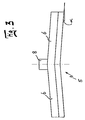
- FIG. 3 shows the application groove in side view. This view clearly shows the groove halves 6 of an application groove 5 .
- the groove halves 6 are tilted outwardly downwards by an adjustable angle ⁇ .
- the angle ⁇ can be between 1° and 15° and preferably 5°.
- the central feed pipe 8 is also arranged between the two groove halves 6 .
Landscapes
- Coating Apparatus (AREA)
- Die Bonding (AREA)
- Non-Metallic Protective Coatings For Printed Circuits (AREA)
- Encapsulation Of And Coatings For Semiconductor Or Solid State Devices (AREA)
- Mixers With Rotating Receptacles And Mixers With Vibration Mechanisms (AREA)
- Application Of Or Painting With Fluid Materials (AREA)
Applications Claiming Priority (3)
| Application Number | Priority Date | Filing Date | Title |
|---|---|---|---|
| DE102007039949 | 2007-08-23 | ||
| DE102007039949.0 | 2007-08-23 | ||
| DE102007039949A DE102007039949B3 (de) | 2007-08-23 | 2007-08-23 | Vorrichtung zum Auftragen einer Suspension auf eine Trägerplatte |
Publications (2)
| Publication Number | Publication Date |
|---|---|
| US20090050054A1 US20090050054A1 (en) | 2009-02-26 |
| US8453594B2 true US8453594B2 (en) | 2013-06-04 |
Family
ID=39791167
Family Applications (1)
| Application Number | Title | Priority Date | Filing Date |
|---|---|---|---|
| US12/196,742 Expired - Fee Related US8453594B2 (en) | 2007-08-23 | 2008-08-22 | Tilted application groove halves for uniformly distributing a suspension to a roller mill |
Country Status (6)
| Country | Link |
|---|---|
| US (1) | US8453594B2 (de) |
| EP (1) | EP2027935B1 (de) |
| AT (1) | ATE444814T1 (de) |
| DE (2) | DE102007039949B3 (de) |
| ES (1) | ES2332956T3 (de) |
| PL (1) | PL2027935T3 (de) |
Cited By (2)
| Publication number | Priority date | Publication date | Assignee | Title |
|---|---|---|---|---|
| US20160052014A1 (en) * | 2013-04-11 | 2016-02-25 | Eos Gmbh Electro Optical Systems | Rotary Coater and Device for the Generative Production of an Object Using the Rotary Coater |
| US20160250659A1 (en) * | 2013-11-07 | 2016-09-01 | Onduline | Machine for dusting a profiled roof tile comprising raised patterns with particulate matter |
Families Citing this family (6)
| Publication number | Priority date | Publication date | Assignee | Title |
|---|---|---|---|---|
| JP5416862B2 (ja) * | 2010-04-02 | 2014-02-12 | アドヴェニラ エンタープライジーズ,インコーポレイテッド | ロールコータ |
| JP6277491B2 (ja) * | 2014-02-25 | 2018-02-14 | パナソニックIpマネジメント株式会社 | 塗膜物の製造装置 |
| PT2960070T (pt) * | 2014-06-24 | 2017-01-09 | Flooring Technologies Ltd | Processo de acabamento de um painel de aglomerado de madeira |
| CN111495697A (zh) * | 2020-05-14 | 2020-08-07 | 盐山万兴新能源有限公司 | 一种气悬浮式油性pvdf涂布系统及其涂布方法 |
| WO2023076373A1 (en) * | 2021-10-27 | 2023-05-04 | Kompac Technologies, Llc | System with sealing chamber |
| US12005471B2 (en) | 2021-10-27 | 2024-06-11 | Kompac Technologies, Llc | System with sealing chamber |
Citations (63)
| Publication number | Priority date | Publication date | Assignee | Title |
|---|---|---|---|---|
| US1068006A (en) * | 1912-05-14 | 1913-07-22 | Thomas Robinson & Son Ltd | Appliance for distributing grain in bins. |
| US1377976A (en) * | 1919-02-28 | 1921-05-10 | Daisy Dell Sheldon | Flour-milling machinery |
| US1768247A (en) * | 1927-11-14 | 1930-06-24 | Gardner Rolland | Nonsegregating chute |
| US1918937A (en) * | 1932-01-04 | 1933-07-18 | Wilbur N Shelton | Coated sheet material presenting an inflated pebbled surface and process of making the same |
| DE616815C (de) | 1934-03-23 | 1935-08-06 | ||
| US2011029A (en) * | 1932-11-22 | 1935-08-13 | Albert E Barnwell | Windshield wiper |
| US2279361A (en) * | 1938-02-19 | 1942-04-14 | Behr Manning Corp | Electrostatic coating process |
| US2293691A (en) * | 1939-10-25 | 1942-08-18 | Distr Of Columbia Paper Mills | Apparatus for coating web material |
| US2333902A (en) * | 1939-05-31 | 1943-11-09 | Cons Water Power And Paper Com | Paper coating device |
| US2572513A (en) * | 1949-05-05 | 1951-10-23 | Wanda L Paul | Envelope moistener |
| US2984874A (en) * | 1956-09-20 | 1961-05-23 | Traue Herbert | Sectional silo |
| US3151368A (en) * | 1961-08-21 | 1964-10-06 | Dietert Co Harry W | Rotary screen moldability controller |
| US3289898A (en) * | 1966-03-08 | 1966-12-06 | Scott Paper Co | Metering and dispensing device for viscous liquids |
| US3620423A (en) * | 1968-07-23 | 1971-11-16 | Golden Wonder Ltd | Apparatus for distributing powder |
| US3885519A (en) * | 1973-06-04 | 1975-05-27 | Korlow Corp | Apparatus for breading food objects |
| US4223632A (en) * | 1978-06-19 | 1980-09-23 | Sps Technologies, Inc. | Apparatus for making self-locking fasteners with a pressure rolled thermoplastic patch |
| US4287827A (en) * | 1979-05-17 | 1981-09-08 | Warner Gordon R | Combined inking and moistening roller |
| JPS5781859A (en) | 1980-11-11 | 1982-05-22 | Sekisui Prefab Homes Ltd | Frame for pasting roller |
| US4358332A (en) * | 1979-10-29 | 1982-11-09 | Polynovus Industries, Inc. | Apparatus for coating paper with a plastic pattern |
| US4377230A (en) * | 1979-10-18 | 1983-03-22 | Carl Schenck Ag. | Process and a device for the distribution of a conveyed flow |
| JPS59177159A (ja) | 1983-03-28 | 1984-10-06 | Yokohama Rubber Co Ltd:The | 接着剤の塗工方法及びその装置 |
| US4603060A (en) * | 1984-01-20 | 1986-07-29 | Mitsubishi Denki Kabushiki Kaisha | Method of manufacturing an electrode for a fuel cell |
| US4611965A (en) * | 1984-06-29 | 1986-09-16 | Dixon Carl R | Gravity-feed grain spreader |
| US4737378A (en) * | 1986-03-01 | 1988-04-12 | Dainippon Screen Mfg. Co., Ltd. | Roll coater control method and roll coater |
| US4738879A (en) * | 1986-07-02 | 1988-04-19 | Xerox Corporation | Coating system |
| US4741929A (en) * | 1987-03-19 | 1988-05-03 | National Gypsum Company | Roll-coating method and apparatus |
| US4949667A (en) * | 1988-04-20 | 1990-08-21 | Dainippon Screen Mfg. Co., Ltd. | Roll coating apparatus for forming a film of a high viscosity coating liquid on a surface |
| US5113760A (en) * | 1987-12-21 | 1992-05-19 | Kinyosha Co., Ltd. | Ink roller for printing machine |
| US5160377A (en) * | 1990-11-14 | 1992-11-03 | Gruma S.A. De C.V. | Apparatus for preventing sticking of stacked food products |
| US5360620A (en) * | 1992-03-16 | 1994-11-01 | Nestec S.A. | Method for wetting and dissolving dry particles |
| US5382291A (en) * | 1993-07-28 | 1995-01-17 | Index S.P.A. Technologie Impermeabili | Apparatus for making decorations on tarred membranes for surface covering in the construction industry |
| US5429676A (en) * | 1992-09-04 | 1995-07-04 | Cca Inc. | Apparatus for simultaneous supply of particles, the apparatus provided further with a function to remove the particles by suction |
| US5670237A (en) * | 1995-06-07 | 1997-09-23 | Mannington Mills, Inc. | Method for making a surface covering product and products resulting from said method |
| US5755883A (en) * | 1990-10-05 | 1998-05-26 | Dainippon Screen Mfg. Co., Ltd. | Roll coating device for forming a thin film of uniform thickness |
| US5863620A (en) * | 1993-05-12 | 1999-01-26 | Ciba-Geigy Ag | Process and apparatus for coating printed circuit boards |
| US6055781A (en) * | 1996-11-04 | 2000-05-02 | Jr Johanson, Inc. | Archbreaking hopper for bulk solids |
| US6129296A (en) * | 1999-06-08 | 2000-10-10 | Poarch Bros. Inc. | Double roll peg feeder assembly for flaking mills |
| JP2002204995A (ja) | 2001-01-09 | 2002-07-23 | Sekisui House Ltd | ロールコーター |
| DE10131027A1 (de) | 2001-02-19 | 2002-08-22 | Hans-Juergen Schaefer | Verfahren und Vorrichtung zur Hochgeschwindigkeitsbeschichtung von Holz-/Kunststoff- und Metalloberflächen mit Pulverlacken |
| US6478564B1 (en) * | 2000-09-08 | 2002-11-12 | The Goodyear Tire & Rubber Company | Adjustable flow channel for an extruder head |
| US6523726B1 (en) * | 2000-05-26 | 2003-02-25 | Imperial Technologies, Inc. | Apparatus and method for controlled feeding of particulate material |
| US20030116085A1 (en) * | 1997-08-05 | 2003-06-26 | Moden Walter L. | Apparatus for modifying the configuration of an exposed surface of a viscous fluid |
| US6592701B1 (en) * | 1997-08-08 | 2003-07-15 | Sollac | Method and device for continuous coating of at least one metal strip with a fluid cross-linkable polymer film |
| US20030143336A1 (en) * | 2000-10-19 | 2003-07-31 | Toyo Seikan Kaisha, Ltd. | Method for trimming resin film |
| DE202004018710U1 (de) | 2004-10-05 | 2005-03-10 | Fritz Egger Gmbh & Co | Vorrichtung zur Herstellung einer strukturierten Oberfläche und Werkstück mit einer strukturierten Oberfläche |
| US6907908B1 (en) * | 2004-04-30 | 2005-06-21 | Pla-Cor Incorporated | Hopper apparatus and method for application of joint compound to corner beads |
| US20060147637A1 (en) * | 2004-12-30 | 2006-07-06 | Cooprider Terrence E | Method for defining a coating fluid pattern |
| US20060177591A1 (en) * | 2005-02-04 | 2006-08-10 | Tse Industries, Inc. | Apparatus for resin-impregnation of fibers for filament winding |
| US20060226067A1 (en) * | 2005-04-07 | 2006-10-12 | Hydration Technologies Inc. | Asymmetric forward osmosis membranes |
| US7204883B2 (en) * | 2003-07-29 | 2007-04-17 | G.D S.P.A. | Feed unit for strip wrapping material |
| US20080156212A1 (en) * | 2004-03-30 | 2008-07-03 | Hiroshi Yamada | Hollow Cylindrical Printing Element |
| US20080196785A1 (en) * | 2005-06-08 | 2008-08-21 | Josef Schmidhuber | Filling Apparatus |
| US20080217985A1 (en) * | 2005-07-26 | 2008-09-11 | Leslie James Botha | Load Transport Bin |
| US20090136679A1 (en) * | 2006-04-06 | 2009-05-28 | Macdermid Printing Solutions Europe Sas | Embossing device, such as a cylinder or a sleeve |
| US20090223591A1 (en) * | 2005-12-23 | 2009-09-10 | University Of Greenwich | Controlling bulk particulate flow rates |
| US20090232998A1 (en) * | 2005-06-30 | 2009-09-17 | Polytype Converting S.A. | Nip coating device and method |
| US7632434B2 (en) * | 2000-11-17 | 2009-12-15 | Wayne O. Duescher | Abrasive agglomerate coated raised island articles |
| US20100053239A1 (en) * | 2008-08-29 | 2010-03-04 | Koji Furukawa | Liquid application apparatus and method, and inkjet recording apparatus |
| US20100242839A1 (en) * | 2008-09-27 | 2010-09-30 | Thomas Fett | Apparatus for applying a liquid to a passing web |
| US7958840B2 (en) * | 2004-10-27 | 2011-06-14 | Surmodics, Inc. | Method and apparatus for coating of substrates |
| US20110244136A1 (en) * | 2010-04-02 | 2011-10-06 | ADCO Engineering | Roll Coater |
| US20110293823A1 (en) * | 2009-02-19 | 2011-12-01 | Atotech Deutschland Gmbh | Method and device for producing a plastic coating |
| US20120318193A1 (en) * | 2010-09-22 | 2012-12-20 | Friz Kaschiertechnik Gmbh | Device for applying adhesives, optionally in a retrofit-free manner |
-
2007
- 2007-08-23 DE DE102007039949A patent/DE102007039949B3/de not_active Expired - Fee Related
-
2008
- 2008-07-26 ES ES08013512T patent/ES2332956T3/es active Active
- 2008-07-26 EP EP08013512A patent/EP2027935B1/de not_active Not-in-force
- 2008-07-26 AT AT08013512T patent/ATE444814T1/de active
- 2008-07-26 PL PL08013512T patent/PL2027935T3/pl unknown
- 2008-07-26 DE DE502008000136T patent/DE502008000136D1/de active Active
- 2008-08-22 US US12/196,742 patent/US8453594B2/en not_active Expired - Fee Related
Patent Citations (63)
| Publication number | Priority date | Publication date | Assignee | Title |
|---|---|---|---|---|
| US1068006A (en) * | 1912-05-14 | 1913-07-22 | Thomas Robinson & Son Ltd | Appliance for distributing grain in bins. |
| US1377976A (en) * | 1919-02-28 | 1921-05-10 | Daisy Dell Sheldon | Flour-milling machinery |
| US1768247A (en) * | 1927-11-14 | 1930-06-24 | Gardner Rolland | Nonsegregating chute |
| US1918937A (en) * | 1932-01-04 | 1933-07-18 | Wilbur N Shelton | Coated sheet material presenting an inflated pebbled surface and process of making the same |
| US2011029A (en) * | 1932-11-22 | 1935-08-13 | Albert E Barnwell | Windshield wiper |
| DE616815C (de) | 1934-03-23 | 1935-08-06 | ||
| US2279361A (en) * | 1938-02-19 | 1942-04-14 | Behr Manning Corp | Electrostatic coating process |
| US2333902A (en) * | 1939-05-31 | 1943-11-09 | Cons Water Power And Paper Com | Paper coating device |
| US2293691A (en) * | 1939-10-25 | 1942-08-18 | Distr Of Columbia Paper Mills | Apparatus for coating web material |
| US2572513A (en) * | 1949-05-05 | 1951-10-23 | Wanda L Paul | Envelope moistener |
| US2984874A (en) * | 1956-09-20 | 1961-05-23 | Traue Herbert | Sectional silo |
| US3151368A (en) * | 1961-08-21 | 1964-10-06 | Dietert Co Harry W | Rotary screen moldability controller |
| US3289898A (en) * | 1966-03-08 | 1966-12-06 | Scott Paper Co | Metering and dispensing device for viscous liquids |
| US3620423A (en) * | 1968-07-23 | 1971-11-16 | Golden Wonder Ltd | Apparatus for distributing powder |
| US3885519A (en) * | 1973-06-04 | 1975-05-27 | Korlow Corp | Apparatus for breading food objects |
| US4223632A (en) * | 1978-06-19 | 1980-09-23 | Sps Technologies, Inc. | Apparatus for making self-locking fasteners with a pressure rolled thermoplastic patch |
| US4287827A (en) * | 1979-05-17 | 1981-09-08 | Warner Gordon R | Combined inking and moistening roller |
| US4377230A (en) * | 1979-10-18 | 1983-03-22 | Carl Schenck Ag. | Process and a device for the distribution of a conveyed flow |
| US4358332A (en) * | 1979-10-29 | 1982-11-09 | Polynovus Industries, Inc. | Apparatus for coating paper with a plastic pattern |
| JPS5781859A (en) | 1980-11-11 | 1982-05-22 | Sekisui Prefab Homes Ltd | Frame for pasting roller |
| JPS59177159A (ja) | 1983-03-28 | 1984-10-06 | Yokohama Rubber Co Ltd:The | 接着剤の塗工方法及びその装置 |
| US4603060A (en) * | 1984-01-20 | 1986-07-29 | Mitsubishi Denki Kabushiki Kaisha | Method of manufacturing an electrode for a fuel cell |
| US4611965A (en) * | 1984-06-29 | 1986-09-16 | Dixon Carl R | Gravity-feed grain spreader |
| US4737378A (en) * | 1986-03-01 | 1988-04-12 | Dainippon Screen Mfg. Co., Ltd. | Roll coater control method and roll coater |
| US4738879A (en) * | 1986-07-02 | 1988-04-19 | Xerox Corporation | Coating system |
| US4741929A (en) * | 1987-03-19 | 1988-05-03 | National Gypsum Company | Roll-coating method and apparatus |
| US5113760A (en) * | 1987-12-21 | 1992-05-19 | Kinyosha Co., Ltd. | Ink roller for printing machine |
| US4949667A (en) * | 1988-04-20 | 1990-08-21 | Dainippon Screen Mfg. Co., Ltd. | Roll coating apparatus for forming a film of a high viscosity coating liquid on a surface |
| US5755883A (en) * | 1990-10-05 | 1998-05-26 | Dainippon Screen Mfg. Co., Ltd. | Roll coating device for forming a thin film of uniform thickness |
| US5160377A (en) * | 1990-11-14 | 1992-11-03 | Gruma S.A. De C.V. | Apparatus for preventing sticking of stacked food products |
| US5360620A (en) * | 1992-03-16 | 1994-11-01 | Nestec S.A. | Method for wetting and dissolving dry particles |
| US5429676A (en) * | 1992-09-04 | 1995-07-04 | Cca Inc. | Apparatus for simultaneous supply of particles, the apparatus provided further with a function to remove the particles by suction |
| US5863620A (en) * | 1993-05-12 | 1999-01-26 | Ciba-Geigy Ag | Process and apparatus for coating printed circuit boards |
| US5382291A (en) * | 1993-07-28 | 1995-01-17 | Index S.P.A. Technologie Impermeabili | Apparatus for making decorations on tarred membranes for surface covering in the construction industry |
| US5670237A (en) * | 1995-06-07 | 1997-09-23 | Mannington Mills, Inc. | Method for making a surface covering product and products resulting from said method |
| US6055781A (en) * | 1996-11-04 | 2000-05-02 | Jr Johanson, Inc. | Archbreaking hopper for bulk solids |
| US20030116085A1 (en) * | 1997-08-05 | 2003-06-26 | Moden Walter L. | Apparatus for modifying the configuration of an exposed surface of a viscous fluid |
| US6592701B1 (en) * | 1997-08-08 | 2003-07-15 | Sollac | Method and device for continuous coating of at least one metal strip with a fluid cross-linkable polymer film |
| US6129296A (en) * | 1999-06-08 | 2000-10-10 | Poarch Bros. Inc. | Double roll peg feeder assembly for flaking mills |
| US6523726B1 (en) * | 2000-05-26 | 2003-02-25 | Imperial Technologies, Inc. | Apparatus and method for controlled feeding of particulate material |
| US6478564B1 (en) * | 2000-09-08 | 2002-11-12 | The Goodyear Tire & Rubber Company | Adjustable flow channel for an extruder head |
| US20030143336A1 (en) * | 2000-10-19 | 2003-07-31 | Toyo Seikan Kaisha, Ltd. | Method for trimming resin film |
| US7632434B2 (en) * | 2000-11-17 | 2009-12-15 | Wayne O. Duescher | Abrasive agglomerate coated raised island articles |
| JP2002204995A (ja) | 2001-01-09 | 2002-07-23 | Sekisui House Ltd | ロールコーター |
| DE10131027A1 (de) | 2001-02-19 | 2002-08-22 | Hans-Juergen Schaefer | Verfahren und Vorrichtung zur Hochgeschwindigkeitsbeschichtung von Holz-/Kunststoff- und Metalloberflächen mit Pulverlacken |
| US7204883B2 (en) * | 2003-07-29 | 2007-04-17 | G.D S.P.A. | Feed unit for strip wrapping material |
| US20080156212A1 (en) * | 2004-03-30 | 2008-07-03 | Hiroshi Yamada | Hollow Cylindrical Printing Element |
| US6907908B1 (en) * | 2004-04-30 | 2005-06-21 | Pla-Cor Incorporated | Hopper apparatus and method for application of joint compound to corner beads |
| DE202004018710U1 (de) | 2004-10-05 | 2005-03-10 | Fritz Egger Gmbh & Co | Vorrichtung zur Herstellung einer strukturierten Oberfläche und Werkstück mit einer strukturierten Oberfläche |
| US7958840B2 (en) * | 2004-10-27 | 2011-06-14 | Surmodics, Inc. | Method and apparatus for coating of substrates |
| US20060147637A1 (en) * | 2004-12-30 | 2006-07-06 | Cooprider Terrence E | Method for defining a coating fluid pattern |
| US20060177591A1 (en) * | 2005-02-04 | 2006-08-10 | Tse Industries, Inc. | Apparatus for resin-impregnation of fibers for filament winding |
| US20060226067A1 (en) * | 2005-04-07 | 2006-10-12 | Hydration Technologies Inc. | Asymmetric forward osmosis membranes |
| US20080196785A1 (en) * | 2005-06-08 | 2008-08-21 | Josef Schmidhuber | Filling Apparatus |
| US20090232998A1 (en) * | 2005-06-30 | 2009-09-17 | Polytype Converting S.A. | Nip coating device and method |
| US20080217985A1 (en) * | 2005-07-26 | 2008-09-11 | Leslie James Botha | Load Transport Bin |
| US20090223591A1 (en) * | 2005-12-23 | 2009-09-10 | University Of Greenwich | Controlling bulk particulate flow rates |
| US20090136679A1 (en) * | 2006-04-06 | 2009-05-28 | Macdermid Printing Solutions Europe Sas | Embossing device, such as a cylinder or a sleeve |
| US20100053239A1 (en) * | 2008-08-29 | 2010-03-04 | Koji Furukawa | Liquid application apparatus and method, and inkjet recording apparatus |
| US20100242839A1 (en) * | 2008-09-27 | 2010-09-30 | Thomas Fett | Apparatus for applying a liquid to a passing web |
| US20110293823A1 (en) * | 2009-02-19 | 2011-12-01 | Atotech Deutschland Gmbh | Method and device for producing a plastic coating |
| US20110244136A1 (en) * | 2010-04-02 | 2011-10-06 | ADCO Engineering | Roll Coater |
| US20120318193A1 (en) * | 2010-09-22 | 2012-12-20 | Friz Kaschiertechnik Gmbh | Device for applying adhesives, optionally in a retrofit-free manner |
Non-Patent Citations (1)
| Title |
|---|
| European Search Report for Corresponding European Application No. EP 08 01 3512. |
Cited By (4)
| Publication number | Priority date | Publication date | Assignee | Title |
|---|---|---|---|---|
| US20160052014A1 (en) * | 2013-04-11 | 2016-02-25 | Eos Gmbh Electro Optical Systems | Rotary Coater and Device for the Generative Production of an Object Using the Rotary Coater |
| US9757760B2 (en) * | 2013-04-11 | 2017-09-12 | Eos Gmbh Electro Optical Systems | Rotary coater with coating element that substantially maintains speed during use, and device for the additive manufacture of an object using the rotary coater |
| US20160250659A1 (en) * | 2013-11-07 | 2016-09-01 | Onduline | Machine for dusting a profiled roof tile comprising raised patterns with particulate matter |
| US9993780B2 (en) * | 2013-11-07 | 2018-06-12 | Onduline | Machine for dusting a profiled roof tile comprising raised patterns with particulate matter |
Also Published As
| Publication number | Publication date |
|---|---|
| DE502008000136D1 (de) | 2009-11-19 |
| EP2027935A1 (de) | 2009-02-25 |
| EP2027935B1 (de) | 2009-10-07 |
| ATE444814T1 (de) | 2009-10-15 |
| DE102007039949B3 (de) | 2008-12-04 |
| US20090050054A1 (en) | 2009-02-26 |
| ES2332956T3 (es) | 2010-02-15 |
| PL2027935T3 (pl) | 2010-04-30 |
Similar Documents
| Publication | Publication Date | Title |
|---|---|---|
| US8453594B2 (en) | Tilted application groove halves for uniformly distributing a suspension to a roller mill | |
| US11958162B2 (en) | CMP pad construction with composite material properties using additive manufacturing processes | |
| KR102295988B1 (ko) | 애디티브 제조 프로세스들을 이용한 복합 재료 특성들을 갖는 cmp 패드 구성 | |
| RU2614488C2 (ru) | Абразивные частицы, имеющие определенные формы, и способы формирования таких частиц | |
| CN1243615C (zh) | 涂洒装置 | |
| US20180169837A1 (en) | Systems and methods for making abrasive articles | |
| US8142859B2 (en) | Method of applying a cement mixture to a honeycomb body | |
| CN1068250C (zh) | 印模涂层方法和印模涂层装置 | |
| TW201108890A (en) | Method, treatment station and assembly for treating a planar material to be treated | |
| JP4342728B2 (ja) | ラッカーの塗布のための方法、システム、および方法またはシステムの使用 | |
| CN103372523B (zh) | 一种两辊涂覆的涂层厚度控制方法 | |
| KR20140127140A (ko) | 가요성 웹을 위한 코팅 시스템 | |
| CA2227501C (en) | Rod holder with separate positionable contact elements for rod metering | |
| EP1346776B1 (de) | Beschichtungsvorrichtung | |
| KR102179615B1 (ko) | 슬러리 도포 방법 및 슬러리 도포 장치 | |
| KR102943354B1 (ko) | 건식전극 재료 공급장치 | |
| KR101659772B1 (ko) | 그라비아 제판 롤의 페이퍼 연마 방법 및 페이퍼 연마 장치 | |
| JP4103596B2 (ja) | 塗布工具および塗布装置 | |
| WO2026072783A1 (en) | Powder system and method for maintaining powder layer uniformity | |
| JP2004216308A (ja) | 塗布工具および塗布装置 |
Legal Events
| Date | Code | Title | Description |
|---|---|---|---|
| AS | Assignment |
Owner name: FLOORING TECHNOLOGIES LTD., MALTA Free format text: ASSIGNMENT OF ASSIGNORS INTEREST;ASSIGNORS:OLDORFF, FRANK;MENIER, CHRISTOPH;REEL/FRAME:021555/0179 Effective date: 20080815 |
|
| STCF | Information on status: patent grant |
Free format text: PATENTED CASE |
|
| FPAY | Fee payment |
Year of fee payment: 4 |
|
| AS | Assignment |
Owner name: FLOORING TECHNOLOGIES LTD., MALTA Free format text: CHANGE OF ADDRESS;ASSIGNOR:FLOORING TECHNOLOGIES LTD.;REEL/FRAME:043994/0113 Effective date: 20170117 |
|
| LAPS | Lapse for failure to pay maintenance fees |
Free format text: PATENT EXPIRED FOR FAILURE TO PAY MAINTENANCE FEES (ORIGINAL EVENT CODE: EXP.); ENTITY STATUS OF PATENT OWNER: LARGE ENTITY |
|
| FEPP | Fee payment procedure |
Free format text: MAINTENANCE FEE REMINDER MAILED (ORIGINAL EVENT CODE: REM.); ENTITY STATUS OF PATENT OWNER: LARGE ENTITY |
|
| STCH | Information on status: patent discontinuation |
Free format text: PATENT EXPIRED DUE TO NONPAYMENT OF MAINTENANCE FEES UNDER 37 CFR 1.362 |
|
| FP | Lapsed due to failure to pay maintenance fee |
Effective date: 20210604 |