US8345123B2 - Image sensing apparatus, registration apparatus, and control method and program therefor - Google Patents
Image sensing apparatus, registration apparatus, and control method and program therefor Download PDFInfo
- Publication number
- US8345123B2 US8345123B2 US12/575,636 US57563609A US8345123B2 US 8345123 B2 US8345123 B2 US 8345123B2 US 57563609 A US57563609 A US 57563609A US 8345123 B2 US8345123 B2 US 8345123B2
- Authority
- US
- United States
- Prior art keywords
- correction information
- unit
- image sensing
- lens
- correction
- Prior art date
- Legal status (The legal status is an assumption and is not a legal conclusion. Google has not performed a legal analysis and makes no representation as to the accuracy of the status listed.)
- Expired - Fee Related, expires
Links
Images


Classifications
-
- H—ELECTRICITY
- H04—ELECTRIC COMMUNICATION TECHNIQUE
- H04N—PICTORIAL COMMUNICATION, e.g. TELEVISION
- H04N5/00—Details of television systems
- H04N5/76—Television signal recording
- H04N5/765—Interface circuits between an apparatus for recording and another apparatus
-
- H—ELECTRICITY
- H04—ELECTRIC COMMUNICATION TECHNIQUE
- H04N—PICTORIAL COMMUNICATION, e.g. TELEVISION
- H04N21/00—Selective content distribution, e.g. interactive television or video on demand [VOD]
- H04N21/40—Client devices specifically adapted for the reception of or interaction with content, e.g. set-top-box [STB]; Operations thereof
- H04N21/41—Structure of client; Structure of client peripherals
- H04N21/4104—Peripherals receiving signals from specially adapted client devices
- H04N21/4113—PC
-
- H—ELECTRICITY
- H04—ELECTRIC COMMUNICATION TECHNIQUE
- H04N—PICTORIAL COMMUNICATION, e.g. TELEVISION
- H04N21/00—Selective content distribution, e.g. interactive television or video on demand [VOD]
- H04N21/40—Client devices specifically adapted for the reception of or interaction with content, e.g. set-top-box [STB]; Operations thereof
- H04N21/41—Structure of client; Structure of client peripherals
- H04N21/422—Input-only peripherals, i.e. input devices connected to specially adapted client devices, e.g. global positioning system [GPS]
- H04N21/4223—Cameras
-
- H—ELECTRICITY
- H04—ELECTRIC COMMUNICATION TECHNIQUE
- H04N—PICTORIAL COMMUNICATION, e.g. TELEVISION
- H04N21/00—Selective content distribution, e.g. interactive television or video on demand [VOD]
- H04N21/60—Network structure or processes for video distribution between server and client or between remote clients; Control signalling between clients, server and network components; Transmission of management data between server and client, e.g. sending from server to client commands for recording incoming content stream; Communication details between server and client
- H04N21/65—Transmission of management data between client and server
- H04N21/654—Transmission by server directed to the client
- H04N21/6547—Transmission by server directed to the client comprising parameters, e.g. for client setup
-
- H—ELECTRICITY
- H04—ELECTRIC COMMUNICATION TECHNIQUE
- H04N—PICTORIAL COMMUNICATION, e.g. TELEVISION
- H04N23/00—Cameras or camera modules comprising electronic image sensors; Control thereof
- H04N23/60—Control of cameras or camera modules
- H04N23/63—Control of cameras or camera modules by using electronic viewfinders
- H04N23/633—Control of cameras or camera modules by using electronic viewfinders for displaying additional information relating to control or operation of the camera
- H04N23/634—Warning indications
-
- H—ELECTRICITY
- H04—ELECTRIC COMMUNICATION TECHNIQUE
- H04N—PICTORIAL COMMUNICATION, e.g. TELEVISION
- H04N23/00—Cameras or camera modules comprising electronic image sensors; Control thereof
- H04N23/60—Control of cameras or camera modules
- H04N23/66—Remote control of cameras or camera parts, e.g. by remote control devices
- H04N23/663—Remote control of cameras or camera parts, e.g. by remote control devices for controlling interchangeable camera parts based on electronic image sensor signals
-
- H—ELECTRICITY
- H04—ELECTRIC COMMUNICATION TECHNIQUE
- H04N—PICTORIAL COMMUNICATION, e.g. TELEVISION
- H04N25/00—Circuitry of solid-state image sensors [SSIS]; Control thereof
- H04N25/60—Noise processing, e.g. detecting, correcting, reducing or removing noise
- H04N25/61—Noise processing, e.g. detecting, correcting, reducing or removing noise the noise originating only from the lens unit, e.g. flare, shading, vignetting or "cos4"
-
- H—ELECTRICITY
- H04—ELECTRIC COMMUNICATION TECHNIQUE
- H04N—PICTORIAL COMMUNICATION, e.g. TELEVISION
- H04N5/00—Details of television systems
- H04N5/76—Television signal recording
- H04N5/765—Interface circuits between an apparatus for recording and another apparatus
- H04N5/77—Interface circuits between an apparatus for recording and another apparatus between a recording apparatus and a television camera
- H04N5/772—Interface circuits between an apparatus for recording and another apparatus between a recording apparatus and a television camera the recording apparatus and the television camera being placed in the same enclosure
-
- H—ELECTRICITY
- H04—ELECTRIC COMMUNICATION TECHNIQUE
- H04N—PICTORIAL COMMUNICATION, e.g. TELEVISION
- H04N2101/00—Still video cameras
-
- H—ELECTRICITY
- H04—ELECTRIC COMMUNICATION TECHNIQUE
- H04N—PICTORIAL COMMUNICATION, e.g. TELEVISION
- H04N9/00—Details of colour television systems
- H04N9/79—Processing of colour television signals in connection with recording
- H04N9/7921—Processing of colour television signals in connection with recording for more than one processing mode
-
- H—ELECTRICITY
- H04—ELECTRIC COMMUNICATION TECHNIQUE
- H04N—PICTORIAL COMMUNICATION, e.g. TELEVISION
- H04N9/00—Details of colour television systems
- H04N9/79—Processing of colour television signals in connection with recording
- H04N9/80—Transformation of the television signal for recording, e.g. modulation, frequency changing; Inverse transformation for playback
- H04N9/82—Transformation of the television signal for recording, e.g. modulation, frequency changing; Inverse transformation for playback the individual colour picture signal components being recorded simultaneously only
- H04N9/8205—Transformation of the television signal for recording, e.g. modulation, frequency changing; Inverse transformation for playback the individual colour picture signal components being recorded simultaneously only involving the multiplexing of an additional signal and the colour video signal
- H04N9/8227—Transformation of the television signal for recording, e.g. modulation, frequency changing; Inverse transformation for playback the individual colour picture signal components being recorded simultaneously only involving the multiplexing of an additional signal and the colour video signal the additional signal being at least another television signal
Definitions
- the present invention relates to an image sensing apparatus, a registration apparatus, and a control method and program therefore.
- the quality of a sensed image of an image sensing apparatus largely depends on the optical characteristics of the lens unit attached at the time of image sensing.
- the optical characteristics of the lens unit that affects the quality of the sensed image include, for example, magnification chromatic aberration, distortion aberration, and decreased marginal illumination.
- image sensing apparatuses capable of image processing of sensed images such as digital still cameras and the like, there are some that carry out correction according to the optical characteristics of the lens unit described above.
- Japanese Patent Laid-Open No. 2002-199410 discloses photoelectrically converting incident light striking an image sensor into analog signals and further into digital signals using A/D conversion, after which optical system image degradation is corrected.
- Japanese Patent Laid-Open No. 2006-267770 discloses an image sensing apparatus that receives from the lens unit that is attached to the apparatus main unit information unique to that lens unit, and through a computer network acquires correction information corresponding to that unique information.
- the present invention has been made in consideration of the above situation, and provides an image sensing apparatus, a registration apparatus, and a control method and program therefore capable of carrying out registration of lens unit correction information with ease.
- an image sensing apparatus including a correction unit that corrects a sensed image based on correction information for an attached lens unit registered in advance in a correction information storage unit, in which the lens unit is detachable, the image sensing apparatus comprising: an acquisition unit that acquires identification information for an attached lens unit from the attached lens unit; a storage unit that stores the identification information acquired by the acquisition unit; a connection unit that connects to an external device storing multiple pieces of correction information for different lens units by identification information; and a control unit that reads out correction information for the identification information stored in the storage unit from the external device and registers the read-out correction information in the correction information storage unit when the external device is connected to the image sensing apparatus by the connection unit.
- a control method for an image sensing apparatus including a correction unit that corrects a sensed image based on correction information for an attached lens unit registered in advance in a correction information storage unit, in which the lens unit is detachable, and a connection unit that connects to an external device storing multiple pieces of correction information for different lens units by identification information
- the control method comprising: an acquisition step of acquiring identification information for an attached lens unit from the attached lens unit; a storage step of storing the identification information acquired in the acquisition step; and a control step of reading out correction information for the identification information stored in the storage step from the external device and registering the read-out correction information in the correction information storage unit when the external device is connected to the image sensing apparatus by the connection unit.
- a registration apparatus that transmits by telecommunication correction information to be registered in a correction information storage unit to an image sensing apparatus, the image sensing apparatus including the correction information storage unit in which correction information for a lens unit/units is registered and an identification information storage unit that stores identification information for the attached lens unit, in which the lens unit is detachable, the registration apparatus comprising: a storage unit that stores multiple pieces of correction information of different lens units by identification information; and a control unit that communicates with the image sensing apparatus, reads out correction information for the identification information stored in the identification information storage unit from the storage unit, and transmits the read-out correction information to the image sensing apparatus as correction information to be registered when the registration apparatus is connected to the image sensing apparatus by telecommunication.
- a control method for a registration apparatus that includes a storage unit that stores multiple pieces of correction information of different lens units by identification information, the correction information storage unit in which correction information for a lens unit/units is registered and an identification information storage unit that stores identification information for an attached lens unit, and that transmits by telecommunication correction information to be registered in a correction information storage unit to an image sensing apparatus in which the lens unit is detachable
- the registration apparatus control method comprising a control step of communicating with the image sensing apparatus, reading out lens unit correction information for the identification information stored in the identification information storage unit from the storage unit, and transmitting the read-out correction information to the image sensing apparatus as correction information to be registered when the registration apparatus is connected to the image sensing apparatus by telecommunication.
- FIG. 1 is a schematic diagram of a lens unit and an image sensing apparatus according to a first embodiment
- FIG. 2 is a block diagram of an internal configuration of the image sensing apparatus according to the first embodiment
- FIGS. 3A and 3B are schematic diagrams illustrating examples of image processing by the image sensing apparatus according to the first embodiment
- FIG. 4 is a flowchart illustrating processing by the image sensing apparatus according to the first embodiment
- FIG. 5 is a flowchart illustrating processing by the image sensing apparatus according to the first embodiment
- FIG. 6 is a diagram illustrating an example of a user interface according to the first embodiment
- FIG. 7 is a schematic diagram illustrating a system configuration according to a second embodiment.
- FIG. 8 is a flowchart illustrating processing by a registration apparatus according to a second embodiment.
- FIG. 1 is a schematic diagram of an image sensing apparatus 2 according to the present embodiment.
- the image sensing apparatus 2 is an interchangeable lens-type digital still camera with a detachable lens unit 1 .
- the lens unit 1 typically has a zoom lens 11 for changing focal length, an aperture mechanism 12 for controlling brightness, and a focus lens 13 for focusing on the subject.
- the lens unit 1 has a mount portion 14 for connecting mechanically to a mount portion 27 of the image sensing apparatus 2 , so that the lens unit 1 can be detachably attached to the image sensing apparatus 2 by screwing the lens unit 1 into the image sensing apparatus 2 , for example.
- the image sensing apparatus 2 reflects light that has passed through the lens unit 1 with a half mirror 21 and forms an image on a focusing screen 24 .
- the light formed on the focusing screen 24 is inverted by a prism 25 , passes through an eyepiece lens 26 , and is viewed as an erect image by a user.
- the half mirror 21 pops up, a shutter 22 opens, and light that has passed through the lens unit 1 forms an image on an image sensor 23 .
- the mount portion 14 of the lens unit 1 incorporates contacts 15 .
- These contacts 15 include terminals for receiving a supply of power from the image sensing apparatus 2 and terminals for exchanging data with the image sensing apparatus 2 (none of which is shown). More specifically, the contacts 15 are respectively assigned to several applications, such as power supply, ground, transmission, reception, clock, and the like.
- the lens unit 1 has a drive unit (not shown) such as a stepping motor or the like for driving the aperture mechanism 12 and the focus lens 13 . Through exchanging data with the image sensing apparatus 2 , driving of the aperture mechanism 12 and the focus lens 13 are controlled from the image sensing apparatus 2 .
- the lens unit 1 has a ROM (not shown) storing identification information such as an identification number or lens ID that is uniquely assigned by individual lens unit or model for identifying the name, individual lens unit, and model of the lens unit 1 . In the event that there has been a request for the above-described identification information though data exchange with the image sensing apparatus 2 , the lens unit 1 sends the identification information stored in the ROM to the image sensing apparatus 2 .
- the image sensor 23 is a CCD or CMOS image sensor or the like.
- the light formed on the image sensor 23 is converted into electrical charges at each of the pixels of the image sensor 23 in accordance with the quantity of incident light.
- Signals generated by a timing generator (TG) 32 drive the image sensor 23 , forwarding the electrical charges accumulated in the pixels of the image sensor 23 and sequentially converting them into voltage signals.
- the converted voltage signals are then sampled and gain-adjusted at a CDS/AGC (Correlated Double Sampling/Automatic Gain Control) 30 and converted into digital signals by an A/D converter 31 .
- CDS/AGC Correlated Double Sampling/Automatic Gain Control
- the image data converted into digital signals by the A/D converter 31 is input to an integrated circuit (IC) 33 .
- the image data input to the IC 33 after input to a WB unit 33 a that computes data for white balance, is temporarily stored in a first memory 35 .
- the first memory 35 may be a RAM or the like.
- the image data temporarily stored in the first memory 35 is once again input to the IC 33 and the following three types of image processing are carried out.
- the image data that is once again input to the IC 33 is converted into lossless-compressed RAW data at a lossless compression unit 33 d that subjects the image data as is to lossless compression and sent to a bus 34 .
- the image data is passed through a low-pass filter and its bandwidth reduced. It is to be noted that, at the thumbnail unit 33 c , as shown in FIG. 3B the image data may be averaged for each block and its bandwidth reduced.
- the bandwidth-reduced image data is subjected to down-sampling by thinning, converted into a thumbnail image smaller in size than the original image, and sent to the bus 34 .
- predetermined image processing is carried out at an image processing unit 33 b on the image data and the processed image data is converted into YCbCr data.
- the YCbCr data is raster-block converted, JPEG compressed at the JPEG compression unit 33 e , and sent to the bus 34 .
- a CPU (Central Processing Unit) 36 centrally controls the operations of each part of the image sensing apparatus 2 . More specifically, immediately after power to the image sensing apparatus 2 is switched on, the CPU 36 initializes all parts of the image sensing apparatus 2 in accordance with program data stored in the second memory 37 and commences communication with the lens unit 1 . In addition, the CPU 36 temporarily stores sensed image data, which is image data that is output to the bus 34 after being subjected to image processing by the IC 33 , in the first memory 35 . Then, the CPU 36 reads out correction information for the lens unit that is attached during image sensing from among correction information for a plurality of lens units stored in the second memory 37 to be described later.
- the CPU 36 Central Processing Unit
- the second memory 37 is a semiconductor memory or the like that readably and writably stores data. In addition to the program data that the CPU 36 executes, the second memory 37 also pre-stores various types of setting data including correction information for a plurality of lens units.
- a switch 40 is connected to the CPU 36 , and the CPU 36 controls the parts of the image sensing apparatus 2 in response to instructions from the user that are input through the switch 40 .
- the switch 40 may be a release switch for accepting an instruction to shoot, operating switches for carrying out various settings, and so forth.
- the CPU 36 in response to the pressing of the release switch, carries out image sensing with the image sensor 23 , and, after image processing by the IC 33 , stores the sensed image data in the external memory 39 .
- the I/F unit 38 is an interface detachably connected to the external memory 39 for writing data to the attached external memory 39 or reading out data stored in the attached external memory 39 .
- the external memory 39 is a recording medium such as a semiconductor memory or a HDD (Hard Disk Drive).
- the I/F unit 38 may be a USB, IEEE1394, LAN port or other such interface communicably connected to an external device such as a PC, a data server on a network, or the like. In this case, the I/F unit 38 can write data to the external device and read data from the external device.
- USB stands for Universal Serial Bus
- IEEE stands for Institute of Electrical and Electronic Engineers.
- a display unit 41 is a display device such as a liquid crystal display (LCD) provided on a rear face of the image sensing apparatus 2 , and displays images under the control of the CPU 36 .
- the display unit 41 can provide electronic viewfinder (EVF) display.
- EVF electronic viewfinder
- the display unit 41 under the control of the CPU 36 , displays operating screens when carrying out various settings using the operating switches of the switch 40 .
- step S 1 the CPU 36 commences exchanging data between the lens unit 1 and the image sensing apparatus 2 (step S 2 ).
- step S 2 the CPU 36 receives lens ID and other such identification information from the lens unit 1 .
- step S 3 the CPU 36 determines whether or not the received lens ID is already registered in the second memory 37 of the image sensing apparatus 2 (step S 3 ).
- step S 3 if the received ID is already registered, the CPU 36 ends this process without registering the lens ID in the second memory 37 (step S 4 ).
- step S 5 the CPU 36 determines whether or not there is space in the registration area of the second memory 37 to store the received lens ID (step S 5 ).
- step S 5 if there is no space in the registration area, the CPU 36 causes the display unit 41 to display a warning message indicting that the registration area is full and there is no space to register the lens ID of the attached lens unit (step S 6 ). After display of the warning message, the CPU 36 ends the process (step S 7 ).
- step S 5 the CPU 36 registers history information including the received lens ID in the registration area of the second memory 37 (step S 8 ). It is to be noted that, in the present embodiment, although the received lens ID and lens name are registered as history information in the registration area of the second memory 37 , it is sufficient if the lens ID is contained in the history information.
- step S 9 the CPU 36 initializes settings related to the newly attached lens unit (step S 9 ) and ends the process (step S 10 ).
- Table 1 shows table data containing information relating to the lens unit that is stored in the registration area.
- the table data relating to the lens unit stored in the registration area is composed of lens ID, lens name, DL, ON/OFF, magnification, on axis, periphery, and distortion as line components, and the lens units as column components. Therefore, a variety of lens unit information can be registered in the table data by lens ID and lens name. Moreover, the number of lines in the table data is limited in advance based on the capacity of the second memory 37 and the like. Therefore, in step S 6 , it is determined whether or not lens IDs and lens names are registered up to the previously limited maximum number of lines.
- the data acquired from the attached lens unit is distinguished by lens ID and lens name so as not to be redundant and sequentially stored.
- the magnification, axis, periphery, and distortion comprise the lens unit correction information, and more specifically amount of correction by each of a plurality of optical characteristics (magnification chromatic aberration, axial chromatic aberration, decreased marginal illumination, and distortion aberration, in that order).
- ON/OFF is setting information for setting whether or not to carry out correction of a sensed image using correction information.
- step S 9 initialized data (0, OFF, NULL value, etc.) is stored for the DL, ON/OFF, magnification, axial, marginal, and distortion for a lens ID and lens name newly registered in step S 8 .
- the DL and the setting information and the correction information have been initialized in step S 9 .
- the DL that is the flag that shows that correction information has been stored is 0, and 0 (or OFF or NULL value) is set for the setting information and for the correction information.
- setting information and correction information have been stored and the DL flag is 1.
- correction information for the attached lens unit is registered in the registration area of the second memory 37 .
- history information that includes identification information acquired from the attached lens unit is stored. It is to be noted that it is not necessary that the history information and the correction information for the attached lens unit be stored in the same registration area, and alternatively, they may be stored in separate storage devices or separate storage areas.
- FIG. 5 a description is given of the process of registering lens data stored in the external memory 39 in the image sensing apparatus 2 , which is a process that the CPU 36 carries out when the external memory 39 is connected to the image sensing apparatus 2 .
- the flowchart shown in FIG. 5 illustrates steps in a process executed by the CPU 36 when the external memory 39 is connected to the image sensing apparatus 2 at the time of turning off the image sensing apparatus 2 . It is to be noted that the process illustrated by the flowchart shown in FIG. 5 is such that, so long as the process is carried out when the external memory 39 is connected to the image sensing apparatus 2 , the process may be executed not when turning off the image sensing apparatus 2 but when turning on the image sensing apparatus 2 .
- the present embodiment illustrates a case in which the external memory 39 , which is a recording medium, is connected to the image sensing apparatus 2 , it goes without saying that the process is the same also in a case in which an external device is connected.
- step S 11 the CPU 36 determines whether or not, of the registered lens units, there are those for which correction information has not been downloaded to the second memory 37 , which it determines by checking the above-described DL flag. That is, in step S 11 , the CPU 36 determines whether or not correction information for lens units with registered lens IDs has been registered. If in step S 11 all the DLs for the registered lens units are 1 and the registered lens unit correction information has all been downloaded (NO), the CPU 36 ends the process (step S 12 ).
- step S 11 determines whether or not lens data storing a variety of information by lens unit is contained in the external memory 39 (step S 13 ).
- the lens data is file data or the like storing a variety of information including correction information by lens name and lens ID.
- the lens data may be CSV (Comma Separated Value) format file data, with a variety of information (lens name, lens ID, correction information) relating to a single lens unit in one line separated by commas, with multiple pieces of lens unit correction information stored by identification information extending over multiple lines.
- the CPU 36 determines whether or not at least a single piece of lens unit correction information is contained in the external memory 39 .
- step S 13 If in step S 13 it is determined that no lens data is contained in the external memory 39 , the CPU 36 causes the display unit 41 to display for several seconds a warning message to the effect that no lens data is contained in the external memory 39 (step S 14 ). More specifically, since no lens data is contained in the external memory 39 , the CPU 36 causes the display unit 41 to display for several seconds a message such as “There are lens units registered for which correction information has not been downloaded.” This warning message display enables the user to ascertain that lens units for which no correction information has been downloaded are registered in the image sensing apparatus 2 . Then, the CPU 36 ends the process (step S 15 ).
- step S 13 it is determined that lens data is contained in the external memory 39 , the CPU 36 determines whether or not correction information for the lens ID of the lens unit for which correction information has not been downloaded is included in that lens data (S 16 ).
- step S 16 If in step S 16 there is no correction information for the lens ID included in the lens data (NO), the CPU 36 causes the display unit 41 to display for several seconds a warning message to the effect that correction information for the lens ID is not included in the lens data (step S 17 ). More specifically, since no correction information for the lens ID is included in the lens data, the CPU 36 causes the display unit 41 to display for several seconds a message such as “There is no correction information. Please update the file.” This warning message display enables the user to ascertain that correction information for the lens unit that is registered in the image sensing apparatus 2 cannot be registered with the lens data that is in the external memory 39 , and that it is necessary to update the lens data. Then, the CPU 36 ends the process (step S 18 ).
- step S 16 correction information for the lens ID is included in the lens data
- the CPU 36 stores that correction information in the second memory 37 as correction information for the lens ID (step S 19 ). More specifically, in step S 19 correction information is registered in the line of the lens ID in the table data described above. It is to be noted that even if there is correction information for the lens ID in the lens data in the external memory 39 that has not yet been registered in the second memory 37 , the CPU 36 does not store that correction information in the second memory 37 . This is because if correction information for a lens unit that has never been attached to the image sensing apparatus 2 is stored in the second memory 37 there is a strong possibility that space in the registration area of the second memory 37 will be needlessly decreased.
- the CPU 36 rewrites the DL flag for that lens ID to 1, to show that download is complete (step S 20 ). Then, the CPU 36 causes the display unit 41 to display for several seconds a message such as “Lens unit correction information storage complete.” (step S 21 ), and ends the process (step S 22 ).
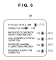
- FIG. 6 shows an example of a setting screen G 1 displayed on the display unit 41 .
- the setting screen G 1 is a screen that is displayed on the display unit 41 by the CPU 36 sequentially executing user interface program data stored in the second memory 37 .
- the CPU 36 through the switch 40 receives operating instructions from the user.
- lens names registered in the second memory 37 can be selected using the selection button G 11 , with setting information and correction information relating to the selected lens name being read out from the second memory 37 and displayed.
- a setting button G 12 queries the user and sets the ON/OFF as to whether or not to carry out correction of a sensed image using the correction information.
- a setting button G 13 queries the user as to the amount of correction relating to magnification chromatic aberration correction in the correction information and receives correction instructions from the user.
- a setting button G 14 queries the user as to the amount of correction relating to axial chromatic aberration correction in the correction information and receives correction instructions from the user.
- a setting button G 15 queries the user as to the amount of correction relating to decreased marginal illumination correction in the correction information and receives correction instructions from the user.
- a setting button G 16 queries the user as to the amount of correction relating to distortion aberration correction in the correction information and receives correction instructions from the user.
- the setting screen G 1 Using the above-described setting screen G 1 , at the image sensing apparatus 2 various settings are implemented with respect to the correction information for the lens unit selected with the selection button G 11 from among the lens units registered in the second memory 37 , using the setting buttons G 12 through G 16 . In addition, the setting results obtained with the setting screen G 1 are reflected as setting information and correction information for the lens units registered in the second memory 37 .
- a lens unit for which correction information has been downloaded can be selected using the user interface that displays the setting screen G 1 on the display unit 41 and receives user operating instructions from the switch 40 .
- the lens unit selected using the user interface it is possible to select an item that turns all the correction functions ON/OFF, that is, it is possible to select whether or not to carry out correction using correction information.
- the amount of correction of individual correction items which are magnification chromatic aberration correction, axial chromatic aberration correction, decreased marginal illumination correction, distortion aberration correction, and so on can be individually adjusted to appropriate amounts.
- reception of operation of the setting buttons G 13 -G 16 may be disabled.
- the user can correct the sensed image by a desired amount of correction, and store the corrected image in the external memory 39 .
- the image sensing apparatus 2 automatically reads out correction information of a lens unit from the external memory 39 and registers the read-out correction information.
- a second embodiment is described using as an example a method of registering from an external device such as a PC or the like connected to the image sensing apparatus 2 , as another method of registering lens unit correction information in the image sensing apparatus 2 . It is to be noted that, in the following description, elements of the image sensing apparatus 2 that are the same as those of the first embodiment are given the same reference numerals and redundant description thereof is omitted.
- FIG. 7 is a schematic diagram illustrating a system configuration according to the second embodiment.
- the image sensing apparatus 2 is connected to a registration apparatus 50 through the above-described I/F unit 38 .
- the registration apparatus 50 is a PC or other such information device, and has a CPU, ROM, RAM, operating devices such as a keyboard and a mouse, and a communications interface for exchanging data with other devices (none of which is shown).
- the CPU securing operating areas in the RAM and sequentially executing program data stored in the ROM, the registration apparatus 50 performs various types of data processing in response to instructions from a user input through the operating devices.
- a display device 51 such as an LCD is connected to the registration apparatus 50 through a communications interface, enabling display of operating screens, data processing results, and the like on the display device 51 .
- the registration apparatus 50 communicates with the image sensing apparatus 2 through the communications interface and can obtain data stored in the image sensing apparatus 2 . More specifically, the registration apparatus 50 exchanges data with the image sensing apparatus 2 through a communications interface such as a USB or the like, and can obtain data corresponding to Table 1 stored in the second memory 37 .
- the recording apparatus 50 is connectable to the internet 60 through a communication interface. Accordingly, by specifying an IP address or the like at the registration apparatus 50 and specifying a data server 61 connected to the internet 60 , it is possible to download data stored on the data server 61 .
- the registration apparatus 50 may be connectable to a storage device or other recording medium through a communications interface, and download data stored on the recording medium. It is to be noted that, in the second embodiment, the registration apparatus 50 downloads data stored on the data server 61 .
- the data server 61 is for example a storage device containing lens data for all lens units, providing lens data to devices from which there is a request (clients) over the internet 60 . Therefore, whereas in the first embodiment lens data containing lens unit correction information was downloaded from an external memory, in this second embodiment lens data can be downloaded from the data server 61 .
- the CPU of the registration apparatus 50 acquires data corresponding to Table 1 stored in the image sensing apparatus 2 and determines whether or not, of the lens units registered in the image sensing apparatus 2 , there are those for which correction information has not been downloaded (step S 31 ). If in step S 31 correction information has been downloaded for all the registered lens units (NO), the CPU displays a message such as “No correction information to be added.” on the display device 51 and ends the diagnostic program (step S 32 ).
- step S 33 if in S 31 there are lens units registered for which correction information has not been downloaded, the CPU determines whether or not the registration apparatus 50 is connected to the internet 60 (step S 33 ). In step S 33 , if the registration apparatus 50 is not connected to the internet 60 , the CPU displays a warning message such as “Please connect to the internet to download correction information.” on the display device 51 (step S 34 ). Then, the CPU ends the diagnostic program (step S 35 ).
- step S 33 the registration apparatus 50 is connected to the internet 60 , the CPU connects the registration apparatus 50 to the data server 61 that is a predetermined connection address containing correction information, using an IP address or the like preset in the diagnostic program (step S 36 ). Then, the CPU downloads lens data for the lens ID of the lens unit, for which no correction information has been downloaded, from the data server 61 to the RAM or the like (step S 37 ).
- step S 37 the CPU may carry out the same processes as those of steps S 13 -S 18 in the first embodiment based on the lens data downloaded to the RAM. In this case, in the event that the downloaded lens data does not satisfy the determinations of step S 13 or S 16 , the same warning messages as in steps S 14 and S 17 are displayed on the display device 51 .
- the CPU causes the display unit 51 to display an indication to the effect that the correction information included in the lens data downloaded from the data server 61 is being registered in the image sensing apparatus 2 (step S 38 ). Then, the CPU transmits the correction information included in the lens data downloaded form the data server 61 to the image sensing apparatus 2 as correction information to be registered, and registers it in the second memory (step S 39 ). Then, the CPU displays a message such as “Correction information update completed.” on the display unit 51 and ends the diagnostic program (step S 40 ).
- a user interface like that shown in FIG. 6 may be provided by sequentially executing the above-described user interface program data. More specifically, various settings relating to the correction information to be transmitted to the image sensing apparatus 2 may be carried out by displaying the above-described setting screen G 1 on the display unit 51 and receiving user instructions from the operating devices. In this case, as with the user interface in the image sensing apparatus 2 , the user can register correction information that corrects the sensed image by a desired correction amount in the image sensing apparatus 2 .
- the registration apparatus 50 is configured to download lens data from the data server 61
- the source of the lens data is not limited to the data server 61 .
- the registration apparatus 50 may be configured to read out lens data from a storage device built into the apparatus or from an external memory connected through an interface.
Landscapes
- Engineering & Computer Science (AREA)
- Multimedia (AREA)
- Signal Processing (AREA)
- Structure And Mechanism Of Cameras (AREA)
- Studio Devices (AREA)
Priority Applications (1)
| Application Number | Priority Date | Filing Date | Title |
|---|---|---|---|
| US13/606,933 US8477213B2 (en) | 2008-10-27 | 2012-09-07 | Image sensing apparatus, registration apparatus, and control method and program therefor |
Applications Claiming Priority (2)
| Application Number | Priority Date | Filing Date | Title |
|---|---|---|---|
| JP2008275923A JP5248980B2 (ja) | 2008-10-27 | 2008-10-27 | 撮像装置及びその制御方法及びプログラム |
| JP2008-275923 | 2008-10-27 |
Related Child Applications (1)
| Application Number | Title | Priority Date | Filing Date |
|---|---|---|---|
| US13/606,933 Continuation US8477213B2 (en) | 2008-10-27 | 2012-09-07 | Image sensing apparatus, registration apparatus, and control method and program therefor |
Publications (2)
| Publication Number | Publication Date |
|---|---|
| US20100103284A1 US20100103284A1 (en) | 2010-04-29 |
| US8345123B2 true US8345123B2 (en) | 2013-01-01 |
Family
ID=42117101
Family Applications (2)
| Application Number | Title | Priority Date | Filing Date |
|---|---|---|---|
| US12/575,636 Expired - Fee Related US8345123B2 (en) | 2008-10-27 | 2009-10-08 | Image sensing apparatus, registration apparatus, and control method and program therefor |
| US13/606,933 Expired - Fee Related US8477213B2 (en) | 2008-10-27 | 2012-09-07 | Image sensing apparatus, registration apparatus, and control method and program therefor |
Family Applications After (1)
| Application Number | Title | Priority Date | Filing Date |
|---|---|---|---|
| US13/606,933 Expired - Fee Related US8477213B2 (en) | 2008-10-27 | 2012-09-07 | Image sensing apparatus, registration apparatus, and control method and program therefor |
Country Status (2)
| Country | Link |
|---|---|
| US (2) | US8345123B2 (enExample) |
| JP (1) | JP5248980B2 (enExample) |
Cited By (2)
| Publication number | Priority date | Publication date | Assignee | Title |
|---|---|---|---|---|
| US20120233515A1 (en) * | 2010-09-13 | 2012-09-13 | Mitsumi Electric Co., Ltd. | Electronic apparatus, method of correcting detection data, and sensor unit |
| US20130242134A1 (en) * | 2012-03-16 | 2013-09-19 | Canon Kabushiki Kaisha | Image capturing apparatus and control method therefor |
Families Citing this family (11)
| Publication number | Priority date | Publication date | Assignee | Title |
|---|---|---|---|---|
| JP5488143B2 (ja) | 2010-04-07 | 2014-05-14 | ソニー株式会社 | 撮像装置及び撮像信号補正方法 |
| US8964039B2 (en) * | 2011-03-30 | 2015-02-24 | Olympus Corporation | Image capturing system and image capturing method |
| JP5868076B2 (ja) | 2011-08-31 | 2016-02-24 | キヤノン株式会社 | 画像処理装置及び画像処理方法 |
| JP5818586B2 (ja) | 2011-08-31 | 2015-11-18 | キヤノン株式会社 | 画像処理装置及び画像処理方法 |
| JP6221251B2 (ja) * | 2013-02-19 | 2017-11-01 | セイコーエプソン株式会社 | 撮影装置、撮影装置の制御方法、撮影装置の制御プログラム |
| JP6104051B2 (ja) * | 2013-05-24 | 2017-03-29 | キヤノン株式会社 | 光学補正データ登録装置、方法及びプログラム |
| JP6478534B2 (ja) * | 2014-09-09 | 2019-03-06 | キヤノン株式会社 | フォーカス制御装置、撮像装置、交換レンズ、フォーカス制御方法およびフォーカス制御プログラム |
| JP2018036415A (ja) * | 2016-08-30 | 2018-03-08 | オリンパス株式会社 | カメラシステム、交換レンズ、カメラシステムの制御方法、及びカメラシステムの制御プログラム |
| US10284861B2 (en) * | 2016-12-09 | 2019-05-07 | Advanced Micro Devices, Inc. | Concurrent image compression and thumbnail generation |
| US20200033560A1 (en) * | 2018-07-30 | 2020-01-30 | Apple Inc. | Electronic Device System With Supplemental Lenses |
| EP4103996A1 (de) * | 2020-02-13 | 2022-12-21 | Leica Camera AG | Digitales beobachtungsgerät |
Citations (11)
| Publication number | Priority date | Publication date | Assignee | Title |
|---|---|---|---|---|
| JP2002199410A (ja) | 2000-12-25 | 2002-07-12 | Canon Inc | 撮像装置、画像劣化補正処理方法及び記憶媒体 |
| US6816625B2 (en) * | 2000-08-16 | 2004-11-09 | Lewis Jr Clarence A | Distortion free image capture system and method |
| JP2005175575A (ja) | 2003-12-08 | 2005-06-30 | Olympus Corp | データ記録装置及びデジタルカメラ |
| US20060152599A1 (en) * | 2002-01-31 | 2006-07-13 | Nikon Corporation | Digital camera |
| JP2006191282A (ja) | 2005-01-05 | 2006-07-20 | Pentax Corp | デジタル一眼レフカメラ |
| JP2006267770A (ja) | 2005-03-25 | 2006-10-05 | Nikon Corp | カメラ |
| US7260322B2 (en) * | 2004-01-21 | 2007-08-21 | Olympus Corporation | Changeable-lens camera, camera system, and focus detection device |
| JP2008096907A (ja) | 2006-10-16 | 2008-04-24 | Sony Corp | レンズ装置、撮像装置及び収差補正方法 |
| US20080111900A1 (en) * | 2006-11-10 | 2008-05-15 | Pentax Corporation | Interchangeable lens and lens-data communication method |
| US20080247744A1 (en) * | 2007-03-29 | 2008-10-09 | Sony Corporation | Image capturing apparatus, image capturing method, and program |
| US20100045802A1 (en) * | 2006-10-06 | 2010-02-25 | Mamoru Oda | Imaging device, image reproducing device, image printing device, imaging device control method, image correcting method for image reproducing device, and image correcting method for image printing device |
-
2008
- 2008-10-27 JP JP2008275923A patent/JP5248980B2/ja not_active Expired - Fee Related
-
2009
- 2009-10-08 US US12/575,636 patent/US8345123B2/en not_active Expired - Fee Related
-
2012
- 2012-09-07 US US13/606,933 patent/US8477213B2/en not_active Expired - Fee Related
Patent Citations (11)
| Publication number | Priority date | Publication date | Assignee | Title |
|---|---|---|---|---|
| US6816625B2 (en) * | 2000-08-16 | 2004-11-09 | Lewis Jr Clarence A | Distortion free image capture system and method |
| JP2002199410A (ja) | 2000-12-25 | 2002-07-12 | Canon Inc | 撮像装置、画像劣化補正処理方法及び記憶媒体 |
| US20060152599A1 (en) * | 2002-01-31 | 2006-07-13 | Nikon Corporation | Digital camera |
| JP2005175575A (ja) | 2003-12-08 | 2005-06-30 | Olympus Corp | データ記録装置及びデジタルカメラ |
| US7260322B2 (en) * | 2004-01-21 | 2007-08-21 | Olympus Corporation | Changeable-lens camera, camera system, and focus detection device |
| JP2006191282A (ja) | 2005-01-05 | 2006-07-20 | Pentax Corp | デジタル一眼レフカメラ |
| JP2006267770A (ja) | 2005-03-25 | 2006-10-05 | Nikon Corp | カメラ |
| US20100045802A1 (en) * | 2006-10-06 | 2010-02-25 | Mamoru Oda | Imaging device, image reproducing device, image printing device, imaging device control method, image correcting method for image reproducing device, and image correcting method for image printing device |
| JP2008096907A (ja) | 2006-10-16 | 2008-04-24 | Sony Corp | レンズ装置、撮像装置及び収差補正方法 |
| US20080111900A1 (en) * | 2006-11-10 | 2008-05-15 | Pentax Corporation | Interchangeable lens and lens-data communication method |
| US20080247744A1 (en) * | 2007-03-29 | 2008-10-09 | Sony Corporation | Image capturing apparatus, image capturing method, and program |
Non-Patent Citations (1)
| Title |
|---|
| Sep. 28, 2012 Japanese Office Action, a copy of which is enclosed without an English Translation, that issued in Japanese Patent Application No. 2008-275923. |
Cited By (4)
| Publication number | Priority date | Publication date | Assignee | Title |
|---|---|---|---|---|
| US20120233515A1 (en) * | 2010-09-13 | 2012-09-13 | Mitsumi Electric Co., Ltd. | Electronic apparatus, method of correcting detection data, and sensor unit |
| US8650460B2 (en) * | 2010-09-13 | 2014-02-11 | Mitsumi Electric Co., Ltd. | Electronic apparatus, method of correcting detection data, and sensor unit |
| US20130242134A1 (en) * | 2012-03-16 | 2013-09-19 | Canon Kabushiki Kaisha | Image capturing apparatus and control method therefor |
| US9736424B2 (en) * | 2012-03-16 | 2017-08-15 | Canon Kabushiki Kaisha | Image capturing apparatus and control method therefor |
Also Published As
| Publication number | Publication date |
|---|---|
| US20120327284A1 (en) | 2012-12-27 |
| US8477213B2 (en) | 2013-07-02 |
| JP5248980B2 (ja) | 2013-07-31 |
| JP2010103948A (ja) | 2010-05-06 |
| US20100103284A1 (en) | 2010-04-29 |
Similar Documents
| Publication | Publication Date | Title |
|---|---|---|
| US8345123B2 (en) | Image sensing apparatus, registration apparatus, and control method and program therefor | |
| US20060268357A1 (en) | System and method for processing images using centralized image correction data | |
| US9001217B2 (en) | Information processing apparatus, method for displaying live view image, and storage medium storing program therefor | |
| US20120147218A1 (en) | Information registration system, information registration method, registration apparatus, and image pickup apparatus | |
| CN102055909B (zh) | 图像拍摄装置以及图像拍摄方法 | |
| CN101815175B (zh) | 信息处理设备及控制方法、摄像设备和图像校正方法 | |
| JP3614126B2 (ja) | デジタルカメラ | |
| JP5631108B2 (ja) | 撮像装置及びその制御方法、並びにプログラム | |
| JP2010016585A (ja) | 情報処理装置および該情報処理装置の制御方法 | |
| JP2003319232A (ja) | 電子撮像装置およびレンズシステム | |
| JP2009005356A (ja) | 撮像装置、画像処理装置、画像処理システム、画像処理方法、及び画像処理プログラム | |
| JP5409050B2 (ja) | 情報処理装置、撮影装置、および情報処理装置の制御方法 | |
| JP5755311B2 (ja) | 情報処理装置、撮影装置、および情報処理装置の制御方法 | |
| JP2002271825A (ja) | 色合わせ方法、色合わせシステムおよびこれらに用いられるテレビジョンカメラ | |
| JP5230315B2 (ja) | 光学補正データ登録プログラム、光学補正データ登録装置及び情報処理装置 | |
| JP2003087608A (ja) | 電子カメラ | |
| JP2018036415A (ja) | カメラシステム、交換レンズ、カメラシステムの制御方法、及びカメラシステムの制御プログラム | |
| JP5474229B2 (ja) | 光学補正データ登録プログラム、光学補正データ登録装置、情報処理装置、および光学補正データ登録方法 | |
| JP6875603B2 (ja) | 撮像装置、撮像方法、及びプログラム | |
| CN117859336A (zh) | 摄像系统、摄像终端及服务器 | |
| JP2004180330A (ja) | デジタルカメラおよび測色計 | |
| JP2019092072A (ja) | 光学補正データ登録装置、その制御方法及びプログラム | |
| JP2003070005A (ja) | 撮像装置、画像処理装置、画像処理システム、画像処理方法、及び画像処理プログラム | |
| JP2012099888A (ja) | フォーカス表示制御可能な撮影装置 | |
| JP2012134698A (ja) | 撮像装置及び画像出力方法 |
Legal Events
| Date | Code | Title | Description |
|---|---|---|---|
| AS | Assignment |
Owner name: CANON KABUSHIKI KAISHA,JAPAN Free format text: ASSIGNMENT OF ASSIGNORS INTEREST;ASSIGNOR:SUGIMORI, MASAMI;REEL/FRAME:023860/0558 Effective date: 20090927 Owner name: CANON KABUSHIKI KAISHA, JAPAN Free format text: ASSIGNMENT OF ASSIGNORS INTEREST;ASSIGNOR:SUGIMORI, MASAMI;REEL/FRAME:023860/0558 Effective date: 20090927 |
|
| REMI | Maintenance fee reminder mailed | ||
| LAPS | Lapse for failure to pay maintenance fees | ||
| STCH | Information on status: patent discontinuation |
Free format text: PATENT EXPIRED DUE TO NONPAYMENT OF MAINTENANCE FEES UNDER 37 CFR 1.362 |
|
| FP | Lapsed due to failure to pay maintenance fee |
Effective date: 20170101 |