US8315391B2 - Information access system, reader/writer device and contactless information storage device - Google Patents
Information access system, reader/writer device and contactless information storage device Download PDFInfo
- Publication number
- US8315391B2 US8315391B2 US11/790,735 US79073507A US8315391B2 US 8315391 B2 US8315391 B2 US 8315391B2 US 79073507 A US79073507 A US 79073507A US 8315391 B2 US8315391 B2 US 8315391B2
- Authority
- US
- United States
- Prior art keywords
- unit
- data
- frequency
- encrypted data
- encryption key
- Prior art date
- Legal status (The legal status is an assumption and is not a legal conclusion. Google has not performed a legal analysis and makes no representation as to the accuracy of the status listed.)
- Expired - Fee Related, expires
Links
Images


Classifications
-
- H—ELECTRICITY
- H04—ELECTRIC COMMUNICATION TECHNIQUE
- H04L—TRANSMISSION OF DIGITAL INFORMATION, e.g. TELEGRAPHIC COMMUNICATION
- H04L9/00—Cryptographic mechanisms or cryptographic arrangements for secret or secure communications; Network security protocols
- H04L9/08—Key distribution or management, e.g. generation, sharing or updating, of cryptographic keys or passwords
- H04L9/0891—Revocation or update of secret information, e.g. encryption key update or rekeying
-
- H—ELECTRICITY
- H04—ELECTRIC COMMUNICATION TECHNIQUE
- H04L—TRANSMISSION OF DIGITAL INFORMATION, e.g. TELEGRAPHIC COMMUNICATION
- H04L2209/00—Additional information or applications relating to cryptographic mechanisms or cryptographic arrangements for secret or secure communication H04L9/00
- H04L2209/80—Wireless
- H04L2209/805—Lightweight hardware, e.g. radio-frequency identification [RFID] or sensor
Definitions
- the present invention relates generally to reading and writing information from and into an active-type contactless information storage device, and in particular to changing an encryption key in an active RFID tag.
- An RF ID tag with a battery power supply or of an active type which is attached to a merchandise article or the like, or carried by a person, transmits an RF signal at a predetermined frequency that carries an ID and other information related to the article or the person, so that the RF signal is received and the information is read out by a reader device.
- the read-out information is further processed by a computer or the like, so that the distribution of the article or the action of the person is monitored and managed.
- the active-type RF ID tag with battery power supply has a larger communication range than a passive-type RF ID tag that receives power from a reader/writer device in a contactless manner, and hence is practical in use.
- the active-type RF ID tag transmits an RF signal in a fixed cycle, has a risk of being tracked by a third party, and hence has a problem in the security.
- an improved active-type RF ID tag that responds only to a tag ID request transmitted by the reader/writer device.
- radio frequencies identification device which includes an integrated circuit including a receiver, a transmitter and a microprocessor.
- the receiver and transmitter together form an active transponder.
- the integrated circuit is preferably a monolithic single die integrated circuit including the receiver, the transmitter and the microprocessor. Because the device includes an active transponder, instead of a transponder which relies on magnetic coupling for power, the device has a much larger range.
- Japanese Patent Application Publication JP 2000-113130-A published on Apr. 21, 2000 describes an IC tag detection system with low power consumption.
- This system includes a plurality of IC tags provided with different set times of day.
- Each IC tag includes a communication circuit, a control unit, a power source unit for supplying power from a battery to them, and time measuring means.
- Each IC tag performs transmission at each prescribed set time of day.
- This system also includes a detector for detecting the presence or absence of the IC tags based on the communication with them. The detector has a communication circuit, and determines the presence or absence of reception from them successively at the respective set times of day of the respective IC tags. Since the IC tag receives no inquiry from the detector, the IC tag can avoid useless reaction and battery consumption.
- Japanese Patent Application Publication JP 2001-251210-A published on Sep. 14, 2001 (which corresponds to U.S. Pat. No. 6,922,402-B1) describes a method of locking a frequency in a transmitter at each of two nodes in a full duplex link, without using a separate reference oscillator in each node.
- the method provides locking of transmission frequencies of both nodes in a full duplex link at the same time by utilizing information of a received frequency to tune carrier frequencies of the transmitters.
- the offset of the carrier frequency of the fist transmitter is detected as the offset of a second corresponding receiver.
- the second receiver shifts the carrier frequency of the second transmitter, in response to the detected offset, to inform the first transmitter about the detected offset.
- the first receiver uses the detected offset to correct the carrier frequency of the first transmitter.
- an information processor includes a host and a reader/writer, and further includes an encryption/key storage unit and a data division/reconstitution unit for dividing data stored in a storage medium.
- the storage medium includes a plurality of RF ID devices which are independently driven.
- the information processor divides data stored in the storage medium, encrypts divided pieces of data with respective different encryption keys and stores these encrypted divided pieces of data in respective RF ID devices. This allows data stored in the storage devices to be confidential on a communication path.
- U.S. Pat. No. 6,980,795-B1 issued on Dec. 27, 2005 (which corresponds to European Patent Application Publication EP 1104213-A2 and to Japanese Patent Application Publication JP 2001-189721-A) describes a wireless network with a cipher key change procedure.
- the wireless network employs a radio network controller and a plurality of assigned terminals which are provided for coding certain data to be transmitted over traffic and control channels and which are provided for changing the respective key necessary for the coding at certain instants.
- the radio network controller sends a message about a change of the key coded with an old cipher key to a terminal.
- the terminal responds with a message coded with a new cipher key as an acknowledgement for the new cipher key.
- an information access system for accessing information stored in a contactless information storage device, and comprises: a reader/writer device connectable to an information processing apparatus, and having a first memory, a first control unit, a first encryption unit for encrypting request data containing an information request to thereby generate encrypted data, a first transmitter unit for transmitting cyclically an information request signal at a first frequency that carries the encrypted data, a first receiver unit adapted to be continuously ready to receive an RF signal at a second frequency different from the first frequency, and a first decryption unit for decrypting another encrypted data carried by an RF signal at the second frequency; and an active contactless information storage device having a second memory, a second control unit, a second receiver unit for sensing a carrier of an RF signal at the first frequency for detection, a second decryption unit for decrypting encrypted data carried by the information request signal at the first frequency to thereby reproduce the request data, a second encryption unit for encrypting, in response
- the first encryption unit In response to a request from the information processing apparatus, and under the control of the first control unit, the first encryption unit encrypts first data containing the information request and a second encryption key with a first encryption key stored in the first memory to thereby generate first encrypted data and encrypts second data containing the information request with the second encryption key stored in the first memory to thereby generate second encrypted data, and the first transmitter unit transmits cyclically the information request signal at the first frequency that carries the first encrypted data and the second encrypted data in a time division manner. Under the control of the second control unit, the second receiver unit senses a carrier of an RF signal at the first frequency in predetermined periods occurring in a predetermined cycle.
- the second receiver unit When the second receiver unit senses and detects a carrier of an RF signal at the first frequency in the particular predetermined period, under the control of the second control unit, the second receiver unit further receives the information request signal at the first frequency, and the second decryption unit decrypts the encrypted data carried by the information request signal at the first frequency with one encryption key stored in the second memory to thereby reproduce the data.
- the one encryption key stored in the second memory is the first or second encryption key.
- the second encryption unit In response to the information request contained in the data reproduced by the second decryption unit, the second encryption unit encrypts the response data with the one encryption key stored in the second memory to thereby generate the response encrypted data, and the second transmitter unit transmits the response signal at the second frequency that carries the response encrypted data.
- the first receiver unit receives the response signal at the second frequency
- the first decryption unit decrypts the response encrypted data carried by the response signal at the second frequency with the corresponding first or second encryption key stored in the first memory to thereby reproduce the response data.
- the second control unit sets the second encryption key as the one encryption key to be stored in the second memory.
- the invention also relates to an active contactless information storage device for use in the information access system described above, and a method for accessing information in a contactless information storage device for use in the information access system described above.
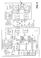
- FIG. 1 is a time chart of a conventional improved active-type RF ID tag and of a reader/writer device (R/W) for reading the RF ID tag;
- FIG. 2 shows the configurations of a further improved active-type RF ID tag as an active contactless information storage device and of a reader/writer device;
- FIG. 3A shows a time chart of processing for transmission of an RF signal carrying a command transmitted from the reader/writer device
- FIG. 3B shows a time chart of a receive ready state and of processing for reception of a received RF signal in the reader/writer device
- FIG. 3C shows a time chart of carrier sensing, processing for reception of a received RF signal, and processing for transmission of an RF signal carrying a response, in the active-type RF ID tag
- FIG. 4 shows a flow chart for the processing performed by the reader/writer device
- FIGS. 5A and 5B show a flow chart for the processing performed by the active-type RF ID tag
- FIG. 6 shows modification of the configurations of FIG. 2 , and illustrates the configurations of a more secure active-type RF ID tag and of a reader/writer device;
- FIG. 7A shows a time chart of processing for transmission for an RF signal carrying a command (CMD) transmitted from the reader/writer device
- FIG. 7B shows a time chart of a receive ready state and of processing for reception of a received RF signal in the reader/writer device
- FIG. 7C shows a time chart of carrier sensing, processing for reception of received RF signals, and processing for transmission of an RF signal carrying a response in the case of successful authentication, in the active-type RF ID tag;
- CMD command
- FIG. 8 shows a flow chart for the processing performed by the reader/writer device
- FIGS. 9A and 9B show a flow chart for the processing performed by the active-type RF ID tag
- FIG. 10 shows configurations of an active RF ID tag and of a reader/writer device, in accordance with an embodiment of the present invention
- FIG. 11A shows a time chart of processing for transmission of an RF signal that carries frames of data, each frame of data containing a tag ID request or information request command (CMD) encrypted with corresponding one of two respective encryption keys, in the reader/writer device
- FIG. 11B shows a time chart of a receive ready state and processing for reception of a received RF signal, in the reader/writer device
- FIGS. 11C and 11D show respective different time charts of carrier sensing, processing for reception of a received RF signal, and processing for transmission of an RF signal that carries a response encrypted with either one of encryption keys, in the RF ID tag;
- FIGS. 12A and 12B show examples of frames of data encrypted with the respective encryption/decryption keys
- FIG. 13 shows an example of a list of tag IDs of registered active RF ID tags that is stored in the memory of the reader/writer device
- FIG. 14 is a flow chart for the processing performed by the reader/writer device.
- FIG. 15 is a flow chart for the processing performed by the active RF ID tag.
- the known improved active-type RF ID tag and the reader/writer device can perform encryption and decryption with one common encryption/decryption key Ke.
- Ke encryption/decryption key
- all of the encryption/decryption keys Ke stored in the reader/writer device and all of the related active RF ID tags have to be changed simultaneously. Accordingly, once the encryption/decryption keys stored in the RF ID tags are started to be changed, the reader/writer devices and any of the RF ID tags cannot be used, until all of the RF ID tags are collected and the change is completed for all of them.
- the reader/writer device may transmit alternately a frame of data that is encrypted with the current encryption key and another frame of data that is encrypted with a new encryption key, so that the encryption keys of a plurality of the RF ID tags can be easily changed over time while the reader/writer device and the RF ID tags are continued to be used.
- An object of the invention is to allow a reader/writer device to simultaneously access contactless information storage devices having respective different encryption keys.
- Another object of the invention is to allow a reader/writer device to easily change an encryption key in a contactless information storage device.
- a reader/writer device can simultaneously access contactless information storage devices having respective different encryption keys, and a reader/writer device can easily change an encryption key in a contactless information storage device.
- FIG. 1 is a time chart of a conventional improved active-type RF ID tag and of a reader/writer device (R/W) for reading the RF ID tag.
- the reader/writer device transmits a command (CMD) and receives a response from the RF ID on the same frequency channel in a time division manner.
- CMD command
- the reader/writer device transmits a command of requesting an ID in a fixed cycle for example, of two (2) seconds and in the duration, for example, of 100 ms. In the remaining time, the reader/writer device is in a state of receive ready.
- each RF ID tag is typically adapted to transmit a response signal to the reader/writer device at a random timing in response to the receipt of a single ID request transmitted by the reader/writer device, so as to avoid possible collision with another response signal.
- Each RF ID tag transmits a response signal to the reader/writer device in a time slot selected at random within a predetermined period of time subsequent to the receipt of the command, so that the probability of collision between the response signals is reduced.
- the reader/writer device is required to extend the duration of the state of receive ready.
- the reader/writer device requires a duration of the receive ready state for 1.5 seconds or longer. This increases the cycle length of command transmission in the reader/writer device.
- the RF ID tag senses, in a fixed cycle, a carrier, i.e., detects the intensity of a received RF signal.
- the RF ID tag is adapted to operate for reception and then operate for transmission, only when a carrier is detected. If the cycle length of transmission in the reader/writer device is two (2) seconds as an example, the carrier sensing duration also requires to have about two or more seconds in order to ensure the detection.
- the RF ID tag when the RF ID tag receives no request from the reader/writer device, the RF ID tag is required to enter into a power down mode of operation in a duration intervening between adjacent carrier sensing durations so that the power consumption is reduced as much as possible and that the battery run time is extended.
- the RF ID tag if about two seconds is reserved for the carrier sensing duration, little time remains for the power down duration, and hence it is difficult to significantly reduce the power consumption.
- the active-type RF ID tag of FIG. 1 which is required to respond to a request command transmitted in a long cycle requires a long carrier sensing duration. This increases the power consumption, and hence reduces the battery run time.
- FIG. 2 shows the configurations of a further improved active-type RF ID tag 200 as an active contactless information storage device and of a reader/writer device 300 .
- a contactless IC card having a configuration similar to that of the active-type RF ID tag 200 may be used in place of the active-type RF ID tag 200 .
- a receiver unit (RX) 250 for receiving and demodulating an RF signal at a frequency f 1 , to thereby reproduce baseband encoded data, and then generating data indicative of the carrier intensity of the received RF signal; a data decoding unit 240 for decoding the encoded data received from the receiver unit 250 in accordance with the predetermined encoding scheme, to thereby generate decoded data; a carrier determination unit 246 for determining the presence or absence of a received RF signal carrier in accordance with the data indicative of the carrier intensity; a wakeup unit 270 for generating a wakeup signal in accordance with a time control sequence having been set up beforehand; a transmission antenna (ANT) 282 coupled to the transmitter unit 230 ; a receiving antenna (ANT) 284 coupled to the receiver unit 250 ; and a battery 290 for supplying power to these elements 210 - 270 .
- RX receiver unit
- the frequencies f 1 and f 2 may be 300 MHz and 301 MHz, respectively, for example.
- the frequencies f 21 are 301 MHz, 302 MHz, . . . , 305 MHz, for example.
- the transmission output power of the transmitter unit (TX) 230 may be 1 mW for example.
- the antennas 282 and 284 may be composed of a single antenna.
- the control unit 210 includes a random number generator 211 for generating a random number for selecting a time slot for transmission, a frequency changing unit 212 for changing the transmitting frequency f 21 , and a timing unit 213 for adjusting a timing for transmission.
- the control unit 210 is always in an active state after power activation, and provides a memory control signal CTRL_M, a data generation control signal CTRL_ENC, a transmission control signal CTRL TX, a reception control signal CTRL RX, a data decode control signal CTRL_DEC, a carrier determination control signal CTRL_CS and a wakeup unit control signal to the memory 214 , the data generation unit 220 , the transmitter unit 230 , the receiver unit 250 , the data decoding unit 240 , the carrier determination unit 246 , and the wakeup unit 270 , respectively.
- the control unit 210 may be a microprocessor or microcomputer that operates in accordance with a program stored in the memory 214 .
- the memory 214 stores information such as, the tag ID (ID_tag) of the RF ID tag 200 , the current time-of-day information T, records of accesses performed by the reader/writer device 300 , a control schedule and a time control sequence of the wakeup unit 270 , the current remaining power level of the battery 290 , a cycle Tcs of sensing a carrier, a time period of processing for reception, a cycle of transmission, and a time period of transmission. These pieces of information are stored and updated under the control of the control unit 210 .
- the control unit 210 regularly or periodically detects the value of the supply voltage of the battery 290 to thereby determine the current remaining battery power level, and then stores information indicative of the remaining power level of the battery 290 into the memory 214 .
- the wakeup unit 270 includes a timer 274 for measuring time and thereby generating a time of day, and is always in an active state after the power activation of the RF ID tag 200 .
- the wakeup unit 270 provides a wakeup signal to the control unit 210 in a predetermined cycle Tcs for sensing a carrier, for example, of two seconds.
- the control unit 210 corrects and updates the current time of day T, the control schedule and the time control sequence in the memory 214 .
- the control unit 210 corrects the time of day of the timer 274 in accordance with the current time of day information T in the memory 214 , and then writes and updates the current time of day T generated by the timer 274 in the memory 214 .
- the data generation unit 220 generates data in a predetermined format containing the tag ID (ID_tag) stored in the memory 214 and the like, then encodes the data in accordance with the predetermined encoding scheme, and then provides the data to the transmitter unit 230 .
- the data may include the remaining battery power level and the access record.
- the data decoding unit 240 decodes the received encoded data in accordance with the predetermined encoding scheme, and then provides the decoded data to the data generation unit 220 and to the control unit 210 .
- the carrier determination unit 246 receives, from the receiver unit 250 , data indicative of the power intensity of the received RF signal carrier, thereby determines the presence or absence of a received carrier to provide the resultant determination to the control unit 210 .
- the reader/writer device 300 includes: a control unit 310 for transmitting and receiving data to and from a host computer (not shown); a memory 314 ; a data generation unit 320 for generating data in a predetermined format containing a command (CMD) and the like received from the control unit 310 , then encoding the data in accordance with the predetermined encoding scheme, and thereby generating encoded data; a transmitter unit (TX) 330 for modulating the carrier with the baseband encoded data received from the data generation unit 320 , and then transmitting an RF signal at a frequency f 1 ; a receiver unit (RX) 350 for receiving an RF signal at a frequency f 2 or RF signals at frequencies f 21 -f 2n ; a data decoding unit 340 for decoding the data received from the receiver unit 350 in accordance with the predetermined encoding scheme, thereby generating baseband decoded data, and then providing the decoded data to the control unit 310 ; a timer 374
- the control unit 310 When the control unit 310 receives a command such as a tag ID or information request command (referred to simply as a tag ID request command hereinafter) from the host computer, it provides data containing the command to the data generation unit 320 .
- the data may contain: the transmission frequency f 2 or f 2 , to be used in the RF ID tag 200 ; the reference current time-of-day information T; and a control schedule and a time control sequence which are new or updated.
- the command may contain an instruction of correcting or updating the time of the timer 274 , in addition to the current time-of-day information T. Further, the command may contain an instruction of correcting or updating the schedule or the sequence stored in the memory 214 , in addition to the control schedule or the time control sequence which are new or updated.
- the control unit 310 may operate in accordance with a program which is stored in the memory 314 .
- FIG. 3A shows a time chart of processing for transmission 42 of an RF signal carrying a command transmitted from the reader/writer device 300 .
- FIG. 3B shows a time chart of a receive ready state 46 and of processing for reception 48 of a received RF signal in the reader/writer device 300 .
- FIG. 3C shows a time chart of carrier sensing 50 and 52 , processing for reception 54 of a received RF signal, and processing for transmission 56 of an RF signal carrying a response, in the active-type RF ID tag 200 .
- the data generation unit 320 of the reader/writer device 300 generates data containing a tag ID request command for the RF ID tag received from the control unit 310 , then encodes the data in accordance with the predetermined encoding scheme, and thereby generates encoded data.
- the transmitter unit 330 continually transmits the RF signal carrying the command in the successive time slots at short intervals in the processing for transmission 42 .
- the control unit 210 in response to a wakeup signal from the wakeup unit 274 , the control unit 210 enables the receiver unit 250 and the carrier determination unit 246 in the periods for carrier sensing 50 and 52 with a predetermined duration, for example of approximately 1-10 ms, occurring in a fixed cycle Tcs, for example of two seconds. This causes the receiver unit 250 to enter into a receive ready state. Then the enabled carrier determination unit 246 determines the presence or absence of a received carrier, in accordance with the data received from the receiver unit 250 indicating the power intensity of the received RF signal carrier.
- the carrier determination unit 246 detects no carrier (ND), and hence determines the absence of a carrier.
- ND no carrier
- the RF ID tag 200 enters into a sleep mode of operation, during which only the control unit 210 and the wakeup unit 270 are enabled or powered on, while the other elements 214 - 250 are disabled or powered down.
- the time length of the sleep period of time 51 may be shorter than the length of time between the ending time of a carrier sensing period 50 and the starting time of the next carrier sensing period 50 .
- the carrier determination unit 246 detects the carrier of the RF signal (DT) in the period for carrier sensing 52 , and hence determines the presence of a carrier.
- the receiver unit 250 and the data decoding unit 240 are enabled in the time period for the subsequent processing for reception 54 with a predetermined duration, for example, of 100 ms. Then, the enabled receiver unit 250 receives and demodulates the RF signal to thereby reproduce encoded data containing a command.
- the enabled data decoding unit 240 decodes the data in accordance with the predetermined encoding scheme, then obtains the command from the data, and then provides the command to the control unit 210 .
- the control unit 210 enables the data generation unit 220 and the transmitter unit 230 in a time period or slot of processing for transmission 56 selected at random within a predetermined period of time, each time slot having a predetermined duration, for example, of 100 ms.
- the enabled data generation unit 220 generates data containing the tag ID (ID_tag) and other required information retrieved from the memory 214 , and then encodes the data in accordance with the predetermined encoding scheme.
- the other required information may include information, such as commodity contents of a package and the number of the contents, a sender, transportation, a route and a destination.
- the enabled transmitter unit 230 modulates the carrier with the response data containing the tag ID, and then transmits the RF signal.
- the receiver unit 350 of the reader/writer device 300 is always in the receive ready state 46 .
- the receiver unit 350 demodulates the received RF signal in the time period of processing for reception 48 and generates encoded data.
- the data decoding unit 350 decodes the encoded data in accordance with the predetermined encoding scheme, then reproduces the response data containing the tag ID, and then provides the reproduced tag ID to the control unit 310 .
- the control unit 310 provides the tag ID to the host computer.
- the host computer processes the tag ID to use for monitoring and managing the article distribution or the persons.
- the total time during which the RF ID tag 200 is not located near the reader/writer device 300 is significantly long.
- the active-type RF ID tag 200 is in a sleep mode of operation for the most time. This significantly reduces the power consumption of the active-type RF ID tag 200 , and hence significantly increases the run time of the battery 290 .
- FIG. 4 shows a flow chart for the processing performed by the reader/writer device 300 .
- FIGS. 5A and 5B show a flow chart for the processing performed by the active-type RF ID tag 200 .
- Step 402 the control unit 310 of the reader/writer device 300 determines whether a tag ID request command has been received from the host computer. The Step 402 is repeated until a request for the tag ID is detected. When a request for the tag ID is detected, the procedure proceeds to Step 412 for processing for transmission and to Step 422 for processing for reception.
- the control unit 310 provides the ID request command and the related information to the data generation unit 320 .
- the data generation unit 320 generates data containing the ID request command, and then encodes the generated data in accordance with a predetermined encoding scheme such as the NRZ (Non-Return-to-Zero) encoding system or the Manchester encoding system.
- the transmitter unit 330 modulates the carrier with the encoded data in the time slot of processing for transmission 42 of FIG. 3A , and then transmits the RF signal at a frequency f 1 .
- the control unit 310 may incorporate, into the ID request command, data for specifying the transmission frequency f 2 or the variable transmission frequencies f 21 used for a response to the ID request command; data indicative of time of day or time slots to be used for the variable transmission frequencies f 21 ; data indicative of the current time of day T; and a control schedule and a time control sequence.
- the reader/writer device 300 may change the frequencies f 21 in the order in a time division manner, selecting one of the frequencies for every set of commands in respective transmission cycles t RW-CY , the number of which corresponds to the time length of one or more cycles of sensing a carrier. This reduces the probability of collision between response RF signals transmitted from a plurality of RF ID tags which simultaneously approach to it. This increases the number of RF ID tags that the reader/writer device 300 can simultaneously identify.
- Step 418 the control unit 210 determines whether the processing for data transmission is to be terminated. If it is determined that the data transmission is terminated, the procedure exits this routine. If it is determined that the processing for data transmission is to be continued, the procedure returns to Step 412 . In FIG. 3A , the data transmission is repeated and continued.
- Step 502 when the RF ID tag 200 is activated, the control unit 210 and the wakeup unit 270 are enabled. Once the RF ID tag 200 is activated, the control unit 210 and the wakeup unit 270 are always enabled, and hence in an active state. In accordance with the timer 274 and with the time control sequence, the wakeup unit 270 provides the control unit 210 with a wakeup signal indicative of the timing for carrier sensing of a received RF signal in a predetermined cycle Tcs. At Step 504 , the control unit 210 determines whether the wakeup signal received from the wakeup unit 270 indicates an ON state. The control unit 210 repeats the Step 504 until the wakeup signal goes to the ON state.
- the control unit 210 at Step 506 enables the receiver unit 250 and the carrier determination unit 246 for a short duration, for example, of approximately 1-10 ms. Then, the enabled receiver unit 250 enters into the state of being ready to receive an RF signal. In accordance with the data received from the receiver unit 250 that is indicative of the received carrier power, the enabled carrier determination unit 246 determines the presence or absence of a received RF signal carrier, and then provides the resultant determination to the control unit 210 . At Step 508 , in accordance with the resultant determination, the control unit 210 determines whether a carrier is detected. If it is determined that no carrier is detected, the control unit 210 at Step 509 disables the receiver unit 250 and carrier determination unit 246 . After that, the procedure proceeds to Step 530 .
- the control unit 210 determines whether the receiver unit 250 has received the RF signal. The Step 512 is repeated until the reception of the RF signal is completed.
- the control unit 210 at Step 514 enables the data decoding unit 240 , while the enabled data decoding unit 240 receives the received data from the receiver unit 250 under the control of the control unit 210 , and then decodes the data in accordance with the predetermined encoding scheme.
- the control unit 210 disables the receiver unit 250 .
- the control unit 210 receives the decoded data containing the ID request command from the data decoding unit 240 , then processes the received command contained in the decoded data, and then stores into the memory 214 the record of access performed by the reader/writer device 300 .
- the control unit 210 corrects or updates the time of the timer 274 of the wakeup unit 270 into the time T.
- the control unit 210 disables the data decoding unit 240 , and in accordance with the ID request command, enables the data generation unit 220 and the transmitter unit 230 in a time slot selected in accordance with a random number from a predetermined number of time slots (e.g., five time slots each having a width of 100 ms) within the predetermined duration (e.g., 500 ms). Such a random number is generated by the random number generator unit 211 . This selected time slot corresponds to the time period of the processing for transmission 56 of FIG. 3C .
- the enabled data generation unit 220 encodes the data containing the tag ID (ID_tag) of the RF ID tag 200 read out from the memory 214 , and then provides the data to the transmitter unit 230 .
- the enabled transmitter unit 230 modulates the carrier with the data containing the tag ID, and then transmits via the antenna 284 an RF signal or RF signals at the predetermined frequency f 2 or specified frequency f 21 .
- the frequency f 21 is changed by the frequency changing unit 212 of the control unit 210 .
- the timing unit 213 adjusts a plurality of successive cycle time slots to occur in a predetermined cycle.
- the control unit 210 disables the data generation unit 220 and the transmitter unit 230 .
- the control unit 210 causes the RF ID tag 200 to enter into the sleep mode of operation. In the sleep mode, basically, the control unit 210 and the wakeup unit 270 solely are maintained in the enabled state, while the other elements 214 - 250 are disabled.
- the control unit 310 enables the receiver unit 350 to enter into the receive ready state.
- the receiver unit 350 waits for the reception of an RF signal at a frequency f 2 (receive ready 46 ), and then receives an RF signal (processing for reception 48 ).
- the control unit 310 determines whether the receiver unit 350 has received the RF signal. The Step 424 is repeated until the reception is completed. If it is determined that the RF signal has been received, the receiver unit 350 at Step 426 provides the received data to the data decoding unit 340 .
- the data decoding unit 340 decodes the received data in accordance with the predetermined encoding scheme to thereby reproduce the response data, and then provides notification of the data reception and the response data to the control unit 310 .
- the control unit 310 transmits the decoded data to the host computer.
- the control unit 310 determines whether the data receive ready state is to be terminated. If it is determined that the data receive ready state is to be terminated, the procedure exits this routine. If it is determined that the data receive ready state is to be continued, the procedure returns to Step 422 . In FIG. 3B , the data receive ready state is repeated and continued.
- the reader/writer device 300 performs transmission cyclically at sufficiently short intervals, and is always in the receive ready state. This reduces significantly the carrier sensing time of the RF ID tag 200 . Thus, when the transmission and reception take place only several times a day, for example, for entry and exit control, the most operating time is used for carrier sensing, and hence the entire power consumption of the RF ID tag 200 is reduced significantly.
- the holidays and a period of time between a predetermined time point and another predetermined time point in the night-time (e.g., 6:00 pm to 6:00 am) of the weekdays may be specified, while a period of time between a predetermined time point and another predetermined time point in the daytime (e.g., 6:00 am to 6:00 pm) of the weekdays may be specified.
- the wakeup unit 270 generates no wakeup signal on the holidays and in the night-time, i.e., the RF ID tag 200 is in a deeper sleep mode of operation, and does not perform carrier sensing at all. In contrast, it performs carrier sensing in a predetermined cycle (e.g., of one second) in the daytime of the weekdays.
- the wakeup unit 270 may generate a wakeup signal depending on the remaining power level of the battery 290 stored in the memory 214 .
- carrier sensing may be performed in a relatively short cycle (e.g., of one second), while, when the remaining battery power level goes below a threshold, carrier sensing may be performed in a relatively long cycle (e.g., of two seconds).
- data representative of the remaining battery power level may be incorporated into the response data of the RF ID tag 200 , and then provided to the host computer via the reader/writer device 300 , so that the host computer displays a warning of battery run-out to a user.
- FIG. 6 shows modification of the configurations of FIG. 2 , and illustrates the configurations of a more secure active-type RF ID tag 202 and of a reader/writer device 302 .
- the data transmitted between the RF ID tag 202 and the reader/writer device 302 is encrypted, and the received data is decrypted to be used for authentication.
- the RF ID tag 202 includes a data generation unit 222 in place of the data generation unit 220 in the RF ID tag 200 of FIG. 2 , and includes a data decoding unit 242 in place of the data decoding unit 240 of FIG. 2 .
- the memory 214 of the RF ID tag 202 stores the current time-of-day information T for authentication, a system ID (ID_system) for authentication, and an encryption/decryption key Ke.
- the memory 214 provides these pieces of information to the data generation unit 222 and the data decoding unit 242 .
- the current time-of-day information T for authentication, the system ID for authentication, and the encryption/decryption key Ke described here are transmitted to the RF ID tag 202 by the reader/writer device 302 beforehand, and then written into the memory 214 by the control unit 210 beforehand.
- the data generation unit 222 includes an encryption unit 224 for encrypting the data to be transmitted, with the encryption key Ke stored in the memory 214 in accordance with a predetermined cryptosystem.
- the data decoding unit 242 includes a decryption unit 244 for decrypting the received data with the encryption/decryption key Ke in accordance with the predetermined cryptosystem.
- the other elements in the configuration of the RF ID tag 202 are similar to those of the RF ID tag 200 , and hence are not described again.
- the system ID indicates a common ID shared by the same group consisting of the reader/writer device 302 and a plurality of RF ID tags including the RF ID tag 202 .
- the common key cryptosystem is employed as the predetermined cryptosystem herein. Alternatively, the public key cryptosystem may be employed.
- the reader/writer device 302 includes a data generation unit 322 in place of the data generation unit 320 in the reader/writer device 300 of FIG. 2 , and includes a data decoding unit 342 in place of the data decoding unit 340 of FIG. 2 .
- the memory 314 of the reader/writer device 302 stores the current time-of-day information T for authentication, the system ID (ID_system) for authentication, and an encryption/decryption key Ke.
- the data generation unit 324 includes an encryption unit 322 for encrypting the data to be transmitted, with the encryption key Ke stored in the memory 314 in accordance with the predetermined cryptosystem.
- the data decoding unit 342 includes a decryption unit 344 for decrypting the received data with the encryption/decryption key Ke in accordance with the predetermined cryptosystem.
- the other elements in the configuration of the reader/writer device 302 are similar to those of the reader/writer device 300 , and hence are not described again.
- FIG. 7A shows a time chart of processing for transmission 42 for an RF signal carrying a tag ID request command (CMD) transmitted from the reader/writer device 302 .
- FIG. 7B shows a time chart of a receive ready state 46 and of processing for reception 48 of a received RF signal in the reader/writer device 302 .
- FIG. 7C shows a time chart of carrier sensing 50 , 52 and 53 , processing for reception 54 and 55 of received RF signals, and processing for transmission 56 of an RF signal carrying a response in the case of successful authentication, in the active-type RF ID tag 202 .
- the data generation unit 322 of the reader/writer device 302 generates data containing a tag ID request command for the RF ID tag that is received from the control unit 310 , and encodes the data in accordance with the predetermined encoding scheme to thereby generate encoded encrypted data.
- the other transmission operation of the reader/writer device 302 is similar to that of the reader/writer device 300 of FIG. 3 A.
- the operations of the receiver unit 250 and carrier determination unit 246 are similar to those shown in FIG. 3C .
- the receiver unit 250 and the carrier determination unit 246 are enabled by the control unit 210 in the periods for carrier sensing 50 , 52 and 53 with the predetermined duration occurring in the fixed cycle, so that the enabled receiver unit 250 enters into a receive ready state.
- the receiver unit 250 and the data decoding unit 242 are enabled in a predetermined time period for the subsequent processing for reception 54 and 55 with the predetermined duration.
- the enabled receiver unit 250 receives and demodulates the RF signal, to thereby reproduce encoded encrypted data containing the command.
- the enabled data decoding unit 242 decodes the data in accordance with the predetermined encoding scheme, then decrypts the encrypted data with the encryption/decryption key Ke in accordance with the predetermined cryptosystem to thereby reproduce the command, and then provides the command to the control unit 210 .
- the control unit 210 authenticates the reader/writer device 302 in accordance with the time-of-day information T and the system ID contained in the command.
- the data generation unit 222 and the transmitter unit 230 are enabled in a time slot of processing for transmission 56 selected at random within a predetermined period of time, each time slot having a predetermined duration.
- the data generation unit 222 encrypts data containing the tag ID (ID_tag), the time-of-day information T, and the system ID (ID_system) retrieved from the memory 214 , with the encryption key Ke in accordance with the predetermined cryptosystem, and then encodes the encrypted data in accordance with the predetermined encoding scheme.
- the transmitter unit 230 modulates the carrier with the encrypted response data containing the tag ID, and then transmits the RF signal.
- the processing is terminated without generating or transmitting the data.
- the receiver unit 350 of the reader/writer device 302 is always in the receive ready state 46 .
- the receiver unit 350 demodulates the received RF signal in the time period of processing for reception 48 , and then reproduces encoded encrypted data.
- the data decoding unit 342 decodes the encoded encrypted data in accordance with the predetermined encoding scheme, then decrypts the decoded encrypted data with the encryption/decryption key Ke in accordance with the predetermined cryptosystem to thereby reproduce the response data containing the tag ID, and then provides the reproduced response to the control unit 310 .
- the control unit 310 authenticates the RF ID tag 202 in accordance with the time-of-day information T and the system ID contained in the response, and then provides the tag ID and other information to the host computer.
- the reader/writer device 302 and the RF ID tag 202 encrypt the data to be transmitted and perform mutual authentication in accordance with the time-of-day information T and the system ID as described above, the data transmitted by the reader/writer device 302 and the RF ID tag 202 , which is intercepted by a third party, has little risk of being decrypted and used improperly. This enhances the security of the reader/writer device 302 and the RF ID tag 202 .
- FIG. 8 shows a flow chart for the processing performed by the reader/writer device 302 .
- FIGS. 9A and 9 B show a flow chart for the processing performed by the active-type RF ID tag 202 .
- Step 402 is similar to that of FIG. 4 , and hence is not described again.
- the control unit 310 provides the ID request command to the data generation unit 322 .
- the data generation unit 322 encrypts data containing the ID request command received from the control unit 310 and containing the current time-of-day information T and the system ID (ID_system) retrieved from the memory 314 , with the encryption key Ke retrieved from the memory 314 in accordance with a predetermined cryptosystem, such as the DES (Data Description Standard), the Triple DES or the AES (Advanced Encryption Standard).
- the data generation unit 322 encodes the encrypted data to thereby generate encoded data.
- the transmitter unit 332 modulates the carrier with the encrypted data, and then transmits the RF signal at the frequency f 1 (processing for transmission 42 in FIG. 7A ).
- Step 418 is similar to that of FIG. 4 , and hence is not described again.
- Steps 502 through 515 are similar to those of FIG. 5 , and hence are not described again.
- the data decoding unit 242 decrypts the decoded data with the encryption/decryption key Ke retrieved from the memory 214 in accordance with the predetermined cryptosystem, and then provides the decrypted data containing the command, the tag ID (ID_tag), the time-of-day information T, and the system ID (ID_system) to the control unit 210 .
- the data may contain a control schedule and a time control sequence.
- control unit 210 Upon receiving the data, the control unit 210 compares the decrypted time-of-day T and system ID with the stored time-of-day T and system ID in the memory 214 , to determine whether the decrypted time information and ID match with the stored time information and ID, in order to authenticate the reader/writer device 302 .
- the control unit 210 determines whether the authentication has been successful. If it is determined that authentication has been unsuccessful, the control unit 210 at Step 520 disables the data decoding unit 242 . Then, the procedure proceeds to Step 530 of FIG. 9B .
- control unit 210 receives from the data decoding unit 242 the decrypted data containing the ID request command, then processes the decrypted received command contained in decoded data, and then stores into the memory 214 the record of access from the reader/writer device 302 .
- the control unit 210 enables the data generation unit 222 and the transmitter unit 230 in a time slot selected at random in accordance with a random number from a predetermined number of time slots within a predetermined period of time. This selected time slot corresponds to the time period of the processing for transmission 56 of FIG. 7C .
- the data generation unit 222 encrypts data containing the tag ID (ID_tag) of the RF ID tag 202 , the time-of-day information T and the system ID (ID_system) read out from the memory 214 , with the encryption key Ke in accordance with the predetermined cryptosystem, then encodes the encrypted data in accordance with the predetermined encoding scheme, and then provides the encoded encrypted data to the transmitter unit 230 .
- the transmitter unit 230 modulates the carrier with the encoded encrypted data, and then transmits the RF signal at a frequency f 2 via the antenna 284 (transmission 56 in FIG. 7C ). Steps 528 and 530 are similar to those of FIG. 5 , and hence are not described again.
- the receiver unit 350 provides the received data to the data decoding unit 342 .
- the data decoding unit 342 decodes the received data in accordance with the predetermined encoding scheme, then decrypts the decoded data in accordance with the predetermined cryptosystem, and then provides the data reception and the decrypted data to the control unit 310 .
- the control unit 310 compares the decrypted time T and system ID with the stored time T and system ID in the memory 314 , to determine whether the decrypted time information and ID match with the stored time information and ID, in order to authenticate the RF ID tag 202 .
- Step 430 the control unit 310 determines whether the authentication has been successful. If it is determined that the authentication has been unsuccessful, the procedure returns to Step 422 . If it is determined that the authentication has been successful, the procedure proceeds to Step 432 . Step 436 is similar to that of FIG. 4 , and hence is not described again.
- the encryption/decryption key Ke For the purpose of security, it is desirable to change sometimes the encryption/decryption key Ke for use in the reader/writer device 302 and the active RF ID tag 202 .
- the reader/writer device 302 and the active RF ID tag 202 of FIG. 6 perform encryption and decryption with one common encryption/decryption key Ke.
- all of the encryption/decryption keys Ke stored in the reader/writer device and all of the related active RF ID tags have to be changed simultaneously.
- the reader/writer device may transmit alternately, in successive time slots at sufficiently short intervals, a frame of data containing the command and a new encryption key that are encrypted with the current encryption key and another frame of data containing the command that is encrypted with the new encryption key, and that each of the RF ID tags may receive and decrypt the new encryption key encrypted with the current encryption key and then set the new encryption key as an encryption/decryption key to be stored in that RF ID tag, so that the encryption keys of a plurality of the RF ID tags can be easily changed over time while the reader/writer device and the RF ID tags are continued to be used.
- FIG. 10 shows configurations of an active RF ID tag 204 and of a reader/writer device 304 , in accordance with an embodiment of the present invention.
- the reader/writer device 304 can use two encryption/decryption keys Ke 1 and Ke 2 simultaneously, and can encrypt a tag ID request command (CMD) and also the encryption/decryption key Ke 2 with the encryption/decryption key Ke 1 and then transmit them as encrypted data.
- the RF ID tag 204 decrypts encrypted data such as a tag ID request command with its current one encryption/decryption key Ke 1 , then encrypts a response with the current encryption/decryption key Ke 1 for transmission.
- the RF ID tag 204 can change the current encryption/decryption key Ke 1 into the new encryption/decryption key Ke 2 received from the reader/writer device 304 .
- the control unit 310 of the reader/writer device 304 receives different pieces of data from the host computer to store them into the memory 314 .
- the memory 314 stores one or two encryption/decryption keys as the first encryption/decryption key Ke 1 and the second encryption/decryption key Ke 2 respectively, and stores a list LID of tag IDs of all of the registered active RF ID tags.
- the control unit 210 of the RF ID tag 204 stores, into the memory 214 , different pieces of data received from the reader/writer device 304 .
- the memory 214 stores one rewritable encryption/decryption key Ke.
- the other elements and operations of the RF ID tag 204 and the reader/writer device 304 are similar to those of the RF ID tag 202 and the reader/writer device 302 in FIG. 6 , and hence will not be described again.
- FIG. 11A shows a time chart of processing for transmission 42 of an RF signal that carries frames of data, each frame of data containing a tag ID request or information request command (CMD) encrypted with corresponding one of two respective encryption keys Ke 1 and Ke 2 , in the reader/writer device 304 .
- FIG. 11B shows a time chart of a receive ready state 46 and processing for reception 48 of a received RF signal, in the reader/writer device 304 .
- FIGS. 11C and 11D show respective different time charts of carrier sensing 50 and 52 , processing for reception 54 of a received RF signal, and processing for transmission 56 of an RF signal that carries a response encrypted with either one of encryption keys Ke 1 and Ke 2 , in the RF ID tag 204 .
- the data generation unit 322 of the reader/writer device 304 generates data containing the tag ID request or information request command and a new encryption/decryption key Ke 2 for the RF ID tag that are received from the control unit 310 , and then encrypts the data with the encryption key Ke 1 in accordance with the predetermined cryptosystem to thereby generate a first frame of encrypted data.
- the data generation unit 322 further generates data containing the tag ID request or information request command, and then encrypts the data with the new encryption/decryption key Ke 2 in accordance with the predetermined cryptosystem to thereby generate a second frame of encrypted data.
- the data generation unit 322 encodes the first and second frames of encrypted data alternately in accordance with the predetermined encoding scheme, to thereby generate two different frames of encoded encrypted data.
- the transmitter unit 230 transmits an RF signal at a frequency f 1 that carries each of the two frames of encrypted data alternately in successive time slots at sufficiently short intervals.
- the other operation for transmission of the reader/writer device 304 is similar to that of the reader/writer device 302 of FIG. 7A , and hence is not described again.
- FIGS. 12A and 12B show examples of frames of data encrypted with the respective encryption/decryption keys Ke 1 and Ke 2 .
- the frame of encrypted data which is encrypted with the encryption/decryption key Ke 1 , includes a frame header, frame data encrypted with the encryption key Ke 1 , and a CRC.
- the frame data includes a plurality of fields of an encryption/decryption key Ke 2 , date and time of day, a system ID, a command, a data length, variable data, and dummy data.
- the frame of encrypted data which is encrypted with the encryption/decryption key Ke 2 , includes a frame header, frame data encrypted with the encryption key Ke 2 , and a CRC.
- the frame data includes a plurality of fields of dummy data in place of an encryption/decryption key, date and time of day, a system ID, a command, a data length, variable data, and dummy data.
- FIG. 13 shows an example of a list LID of tag IDs of registered active RF ID tags that is stored in the memory 314 of the reader/writer device 304 .
- the list LID includes the tag IDs of the registered RF ID tag and their currently effective encryption/decryption keys Ke 1 /Ke 2 .
- the receiver unit 250 and the carrier determination unit 246 performs carrier sensing similarly to that of FIG. 7C .
- the receiver unit 250 and the data decoding unit 242 are enabled in a predetermined duration, such as a time length of three frames of data, in the period of subsequent processing for reception 54 .
- the receiver unit 250 receives and demodulates an RF signal at the frequency f 1 , and thereby generates two successive frames of encoded encrypted data containing respective different commands.
- the time length of three frames of data should be sufficient to receive two successive frames of encoded encrypted data.
- the control unit 210 authenticates the reader/writer device 304 in accordance with the time of day information T and the system ID contained together with the command.
- the receiver unit 350 of the reader/writer device 304 is in the receive ready state 46 , and then demodulates the received RF signal in the period of processing for reception 48 to thereby reproduce the frame of the encoded encrypted data.
- the data decoding unit 342 decodes the encoded encrypted data in accordance with the predetermined encoding scheme, then decrypts the decoded encrypted data in accordance with the predetermined cryptosystem with the encryption/decryption key Ke 1 or Ke 2 stored in the memory 314 to thereby reproduce the response data containing the tag ID, and then provides the reproduced response to the control unit 310 .
- the control unit 310 authenticates the RF ID tag 204 in accordance with the time-of-day information T and the system ID contained in the response, and then provides the tag ID and other information to the host computer.
- the control unit 310 changes the encryption/decryption key Ke 1 of the tag ID of the corresponding RF ID tag 204 in the list LID stored in the memory 314 into the new encryption/decryption Ke 2 .
- the receiver unit 250 and the data decoding unit 242 are enabled in the next period of processing for reception 54 . Then, the receiver unit 250 receives and demodulates the RF signal at the frequency f 1 , and thereby generates two successive pieces of encoded encrypted data containing the respective commands.
- the control unit 210 authenticates the reader/writer device 304 in accordance with the data contained together with the command.
- the data generation unit 222 and the transmitter unit 230 are enabled in a period of processing for transmission 56 selected at random within a predetermined period of time.
- the transmitter unit 230 modulates the carrier with the response data containing the encrypted tag ID, and thereby transmits an RF response signal at the frequency f 2 or f 21 .
- the RF ID tag 204 performs processing similar to that of the second processing for reception 54 and processing for transmission 56 of FIG. 11C .
- the reader/writer device 304 can change the encryption/decryption key Ke 1 to the encryption/decryption key Ke 2 in the RF ID tags over time, which enter into the communication range of the reader/writer device 304 .
- the reader/writer device 304 can ultimately change the encryption/decryption keys of all of the RF ID tags 204 .
- FIG. 14 is a flow chart for the processing performed by the reader/writer device 304 .
- FIG. 15 is a flow chart for the processing performed by the active RF ID tag 204 .
- Step 614 in accordance with Steps 414 - 418 and Steps 422 - 436 of FIG. 8 , the control unit 310 of the reader/writer device 304 encrypts data to be transmitted containing a tag ID request command in accordance with the predetermined cryptosystem with the same one encryption/decryption key Ke 1 which has been received from the host computer and then stored as each of the encryption/decryption keys Ke 1 and Ke 2 in the memory 314 .
- the control unit 310 then generates repeatedly in successive time slots at sufficiently short intervals a frame of encoded data which has been encoded in accordance with the predetermined encoding scheme, then modulates the carrier with the frame of the encoded data, and thereby transmits the RF signal at the frequency f 1 .
- the control unit 310 determines whether it has a new received encryption/decryption key (Ke 2 ) that is different from the encryption/decryption key Ke 1 and is received from the host computer, i.e., whether it is required to perform the processing of changing the encryption/decryption key Ke 1 into a new encryption/decryption key (Ke 2 ) in the reader/writer 304 and the associated active RF ID tags. If it is determined that it is not required to perform the processing of changing the encryption/decryption key Ke 1 , the procedure returns to Step 614 .
- Ke 2 new received encryption/decryption key
- the control unit 310 sets the new encryption/decryption key (Ke 2 : Ke 1 ) to the encryption/decryption key Ke 2 in the memory 314 , while maintaining the current encryption/decryption key Ke 1 in the memory 314 .
- the control unit 310 encrypts data to be transmitted containing a tag ID request command and the new encryption/decryption key Ke 2 with the current encryption key Ke 1 in accordance with the predetermined cryptosystem to thereby generate first encrypted data, then encrypts data to be transmitted containing a tag ID request command with the new encryption key Ke 2 ( ⁇ Ke 1 ) in accordance with the predetermined cryptosystem to thereby generate second encrypted data, then encodes the first and second frames of encrypted data alternately in accordance with the predetermined encoding scheme to thereby generate frames of encoded data, and then modulates the carrier with the frames of the encoded data to thereby transmit the RF signal at the frequency f 1 continually.
- the control unit 310 looks up the list LID in the memory 314 , and thereby determines whether the new encryption/decryption key Ke 2 has been set up in all of the RF ID tags in the list LID. If it is determined that the new encryption/decryption key Ke 2 is set up not in all RF ID tags, then the procedure returns to Step 620 .
- the control unit 310 at Step 624 deletes the former encryption/decryption key Ke 1 , and then sets the new encryption/decryption key Ke 2 also to the encryption/decryption key Ke 1 . After that, the procedure returns to Step 614 .
- the control unit 210 authenticates the reader/writer device 304 in accordance with the time-of-day information T and the system ID contained in the command.
- the data generation unit 222 and the transmitter unit 230 are enabled in a period of processing for transmission 56 selected at random within the predetermined of time.
Applications Claiming Priority (2)
| Application Number | Priority Date | Filing Date | Title |
|---|---|---|---|
| JP2006-290788 | 2006-10-26 | ||
| JP2006290788A JP4910629B2 (ja) | 2006-10-26 | 2006-10-26 | 情報アクセス・システム、読取り書込み装置およびアクティブ型非接触情報記憶装置 |
Publications (2)
| Publication Number | Publication Date |
|---|---|
| US20080104392A1 US20080104392A1 (en) | 2008-05-01 |
| US8315391B2 true US8315391B2 (en) | 2012-11-20 |
Family
ID=39331806
Family Applications (1)
| Application Number | Title | Priority Date | Filing Date |
|---|---|---|---|
| US11/790,735 Expired - Fee Related US8315391B2 (en) | 2006-10-26 | 2007-04-27 | Information access system, reader/writer device and contactless information storage device |
Country Status (3)
| Country | Link |
|---|---|
| US (1) | US8315391B2 (zh) |
| JP (1) | JP4910629B2 (zh) |
| CN (1) | CN101169833B (zh) |
Cited By (1)
| Publication number | Priority date | Publication date | Assignee | Title |
|---|---|---|---|---|
| US9064196B1 (en) * | 2008-03-13 | 2015-06-23 | Impinj, Inc. | RFID tag dynamically adjusting clock frequency |
Families Citing this family (16)
| Publication number | Priority date | Publication date | Assignee | Title |
|---|---|---|---|---|
| US8116454B2 (en) | 2007-07-23 | 2012-02-14 | Savi Technology, Inc. | Method and apparatus for providing security in a radio frequency identification system |
| WO2009046088A1 (en) * | 2007-10-01 | 2009-04-09 | Neology, Inc. | Systems and methods for preventing transmitted cryptographic parameters from compromising privacy |
| JP4521678B2 (ja) * | 2007-11-19 | 2010-08-11 | フェリカネットワークス株式会社 | 通信システム、情報処理方法、プログラム、及び情報処理装置 |
| US8905312B2 (en) * | 2007-11-21 | 2014-12-09 | Infineon Technologies Ag | Identification of contactless cards |
| US8230462B2 (en) * | 2008-01-23 | 2012-07-24 | Newport Media, Inc. | Fast channel switching for encrypted mobile multimedia multicast system |
| CN101308546B (zh) * | 2008-05-20 | 2011-04-20 | 上海华申智能卡应用系统有限公司 | 具有多级保护的安全存储结构的射频标签数据保护方法 |
| CN101998388B (zh) * | 2009-08-21 | 2015-05-20 | 中兴通讯股份有限公司 | 安全信息的交互方法和装置 |
| TW201136276A (en) * | 2010-04-08 | 2011-10-16 | Gemtek Technology Co Ltd | Wireless packet relay apparatus and wireless set-top box |
| CN102223349A (zh) * | 2010-04-13 | 2011-10-19 | 正文科技股份有限公司 | 无线封包转发装置及无线机上盒 |
| US8352749B2 (en) * | 2010-12-17 | 2013-01-08 | Google Inc. | Local trusted services manager for a contactless smart card |
| JP6047933B2 (ja) * | 2012-06-05 | 2016-12-21 | 凸版印刷株式会社 | 情報処理装置、情報処理方法及び情報処理システム |
| CN104765999B (zh) * | 2014-01-07 | 2020-06-30 | 腾讯科技(深圳)有限公司 | 一种对用户资源信息进行处理的方法、终端及服务器 |
| CN108962289B (zh) * | 2018-06-29 | 2020-05-12 | 北京同方光盘股份有限公司 | 基于光盘同步帧追加隐藏的标识数据的方法及装置 |
| CN111954195B (zh) * | 2020-08-13 | 2022-03-11 | 华中科技大学 | 一种rfid标签数字基带系统 |
| CN112565656B (zh) * | 2020-11-27 | 2023-05-23 | Oppo广东移动通信有限公司 | 视频通话方法、装置、系统、电子设备及存储介质 |
| CN116455834B (zh) * | 2023-06-19 | 2023-08-11 | 西华大学 | 一种基于控制序列的数据链分级访问控制方法 |
Citations (7)
| Publication number | Priority date | Publication date | Assignee | Title |
|---|---|---|---|---|
| WO1997043740A1 (en) | 1996-05-13 | 1997-11-20 | Micron Communications, Inc. | Radio frequency data communications device |
| JP2000113130A (ja) | 1998-10-05 | 2000-04-21 | Rohm Co Ltd | Icタグ及びタグ検知システム |
| JP2001189721A (ja) | 1999-11-29 | 2001-07-10 | Koninkl Philips Electronics Nv | 暗号鍵交換手順を有する無線ネットワーク |
| JP2001251210A (ja) | 2000-01-25 | 2001-09-14 | Agilent Technol Inc | リンク両端間における相互周波数ロック |
| JP2005141529A (ja) | 2003-11-07 | 2005-06-02 | Hitachi Ltd | 情報通信システム及び情報記憶媒体 |
| US20060065731A1 (en) * | 2002-10-25 | 2006-03-30 | Symbol Technologies, Inc. | Methods and systems for the negotiation of a population of RFID tags with improved security |
| US20060175408A1 (en) * | 2002-09-05 | 2006-08-10 | Becker Robert C | RFID tag and communication protocol for long range tag communications and power efficiency |
Family Cites Families (8)
| Publication number | Priority date | Publication date | Assignee | Title |
|---|---|---|---|---|
| JPH063905B2 (ja) * | 1984-08-07 | 1994-01-12 | 日本電信電話株式会社 | センタと利用者間の相手認証方法 |
| JP2000163538A (ja) * | 1998-11-30 | 2000-06-16 | Dainippon Printing Co Ltd | 情報記憶媒体 |
| JP2001143023A (ja) * | 1999-11-18 | 2001-05-25 | Nippon Signal Co Ltd:The | 非接触式icカードリーダライタ |
| JP2004186814A (ja) * | 2002-11-29 | 2004-07-02 | Fujitsu Ltd | 共通鍵暗号化通信システム |
| CN1540583A (zh) * | 2003-10-27 | 2004-10-27 | 江苏瑞福智能科技有限公司 | 存储式电子标签安全应用及防伪鉴别方法 |
| JP4390600B2 (ja) * | 2004-03-16 | 2009-12-24 | 東京特殊電線株式会社 | 無線タグ、送受信装置および管理装置 |
| JP2006053800A (ja) * | 2004-08-12 | 2006-02-23 | Ntt Docomo Inc | 情報提供方法、情報提供システム及び中継装置 |
| JP4681314B2 (ja) * | 2005-02-10 | 2011-05-11 | フェリカネットワークス株式会社 | 無線通信システム,リーダ/ライタ装置,鍵管理方法,およびコンピュータプログラム |
-
2006
- 2006-10-26 JP JP2006290788A patent/JP4910629B2/ja not_active Expired - Fee Related
-
2007
- 2007-04-27 US US11/790,735 patent/US8315391B2/en not_active Expired - Fee Related
- 2007-05-15 CN CN2007101074943A patent/CN101169833B/zh not_active Expired - Fee Related
Patent Citations (10)
| Publication number | Priority date | Publication date | Assignee | Title |
|---|---|---|---|---|
| WO1997043740A1 (en) | 1996-05-13 | 1997-11-20 | Micron Communications, Inc. | Radio frequency data communications device |
| JP2000113130A (ja) | 1998-10-05 | 2000-04-21 | Rohm Co Ltd | Icタグ及びタグ検知システム |
| JP2001189721A (ja) | 1999-11-29 | 2001-07-10 | Koninkl Philips Electronics Nv | 暗号鍵交換手順を有する無線ネットワーク |
| US20050282521A1 (en) * | 1999-11-29 | 2005-12-22 | Christoph Hermann | Wireless network with a cipher key change procedure |
| US6980795B1 (en) | 1999-11-29 | 2005-12-27 | Koninklijke Philips Electronics N.V. | Wireless network with a cipher key change procedure |
| JP2001251210A (ja) | 2000-01-25 | 2001-09-14 | Agilent Technol Inc | リンク両端間における相互周波数ロック |
| US6922402B1 (en) | 2000-01-25 | 2005-07-26 | Agilent Technologies, Inc. | Mutual frequency locking across a link |
| US20060175408A1 (en) * | 2002-09-05 | 2006-08-10 | Becker Robert C | RFID tag and communication protocol for long range tag communications and power efficiency |
| US20060065731A1 (en) * | 2002-10-25 | 2006-03-30 | Symbol Technologies, Inc. | Methods and systems for the negotiation of a population of RFID tags with improved security |
| JP2005141529A (ja) | 2003-11-07 | 2005-06-02 | Hitachi Ltd | 情報通信システム及び情報記憶媒体 |
Non-Patent Citations (1)
| Title |
|---|
| Feldhofer, Martin, "A Proposal for an Authentication Protocol in a Security Layer for RFID Smart Tags", The 12th IEEE Mediterranean Electrotechnical Conference, MELECON 2004, IEEE Proceedings, May 2004. * |
Cited By (2)
| Publication number | Priority date | Publication date | Assignee | Title |
|---|---|---|---|---|
| US9064196B1 (en) * | 2008-03-13 | 2015-06-23 | Impinj, Inc. | RFID tag dynamically adjusting clock frequency |
| US9165170B1 (en) * | 2008-03-13 | 2015-10-20 | Impinj, Inc. | RFID tag dynamically adjusting clock frequency |
Also Published As
| Publication number | Publication date |
|---|---|
| CN101169833A (zh) | 2008-04-30 |
| JP4910629B2 (ja) | 2012-04-04 |
| US20080104392A1 (en) | 2008-05-01 |
| JP2008108095A (ja) | 2008-05-08 |
| CN101169833B (zh) | 2010-06-09 |
Similar Documents
| Publication | Publication Date | Title |
|---|---|---|
| US8315391B2 (en) | Information access system, reader/writer device and contactless information storage device | |
| US8035488B2 (en) | Information access system and active-type contactless information storage device | |
| US7821397B2 (en) | Information access system, reader/writer device, and active-type contactless information storage device | |
| US7536152B2 (en) | Information access system and active-type contactless information storage device | |
| US7710242B2 (en) | Information access system and active-type contactless information storage device | |
| US7994899B2 (en) | Information access system and method for accessing information in contactless information storage device | |
| JP4992971B2 (ja) | センサによる検出値を蓄積するアクティブ非接触情報記憶装置 | |
| JP5141173B2 (ja) | 読取り書込み装置との間で無線通信が可能な情報装置、プログラムおよび方法 | |
| EP2149850B1 (en) | Information access system, information storage device and reader/writer device | |
| EP1855430A2 (en) | System, device, method, computer program and recording medium for communication apparatus and for processing information | |
| US20100066505A1 (en) | Information access system, contactless reader and writer device, and contactless information storage device | |
| US8130109B2 (en) | Information accessing system, information apparatus, recording medium and method for accessing information | |
| JP4915060B2 (ja) | 情報アクセス・システムおよびアクティブ型非接触情報記憶装置 | |
| US8487767B2 (en) | Information access system, information device, reader/writer and recording medium | |
| JP2007065960A (ja) | 情報アクセス・システムおよびアクティブ型非接触情報記憶装置 | |
| JP4910509B2 (ja) | 情報アクセス・システム |
Legal Events
| Date | Code | Title | Description |
|---|---|---|---|
| AS | Assignment |
Owner name: FUJITSU LIMITED, JAPAN Free format text: ASSIGNMENT OF ASSIGNORS INTEREST;ASSIGNORS:INANO, SATOSHI;YAMADA, ISAMU;SHIOTSU, SHINICHI;AND OTHERS;REEL/FRAME:019291/0682 Effective date: 20070124 |
|
| FEPP | Fee payment procedure |
Free format text: PAYOR NUMBER ASSIGNED (ORIGINAL EVENT CODE: ASPN); ENTITY STATUS OF PATENT OWNER: LARGE ENTITY |
|
| REMI | Maintenance fee reminder mailed | ||
| LAPS | Lapse for failure to pay maintenance fees | ||
| STCH | Information on status: patent discontinuation |
Free format text: PATENT EXPIRED DUE TO NONPAYMENT OF MAINTENANCE FEES UNDER 37 CFR 1.362 |
|
| FP | Lapsed due to failure to pay maintenance fee |
Effective date: 20161120 |