US809690A - Razor-blade holder. - Google Patents
Razor-blade holder. Download PDFInfo
- Publication number
- US809690A US809690A US26068605A US1905260686A US809690A US 809690 A US809690 A US 809690A US 26068605 A US26068605 A US 26068605A US 1905260686 A US1905260686 A US 1905260686A US 809690 A US809690 A US 809690A
- Authority
- US
- United States
- Prior art keywords
- plates
- sections
- razor
- blade
- handle
- Prior art date
- Legal status (The legal status is an assumption and is not a legal conclusion. Google has not performed a legal analysis and makes no representation as to the accuracy of the status listed.)
- Expired - Lifetime
Links
- 230000015572 biosynthetic process Effects 0.000 description 1
- 238000010276 construction Methods 0.000 description 1
- 239000002184 metal Substances 0.000 description 1
- 238000000034 method Methods 0.000 description 1
Images
Classifications
-
- B—PERFORMING OPERATIONS; TRANSPORTING
- B26—HAND CUTTING TOOLS; CUTTING; SEVERING
- B26B—HAND-HELD CUTTING TOOLS NOT OTHERWISE PROVIDED FOR
- B26B5/00—Hand knives with one or more detachable blades
- B26B5/006—Hand knives with one or more detachable blades specially adapted for using razor blades as blades
Definitions
- the urpose of the invention is to provide a simp e, economic, and readily operated 1o holder for the blades of safety-razors when it is necessary to hone or strop the same, and, furthermore, to so construct the holder that the blade can be quickly and conveniently introduced into the holder or removed there I 5 from and held firmly between the jaws of the holder during the sharpening process without the use of set-screws or their equivalents.
- the invention consists in the novel construction and combination of the several parts, as will be hereinafter fully set forth,
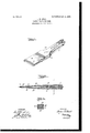
- Figure 1 is a perspective view of'the improved holder with a razor-blade in position for stropping.
- Fig. 2 is a longitudinal vertical 0 section through the same, and
- Fig. 3 is a transverse section taken practically on the line 3 3 of Fig. 2.
- the device consists of two body-plates A and B, adapted to lie closely one upon the 3 5 other.
- the body-plates are of like formation, and each comprises a jaw-section 10, and a handle-section 11 of reduced width.
- the opposing faces 12 of the body-plates A and B are perfectly straight and flat, as is illustrated in Fig. 2 but the outer faces of the jaw-sections 10 are tapered in direction of their outer ends, being thinnest at the latter points.
- the razor-blade 14 to be sharpened is in- 5 troduced between the thinner ends of the jaw-sections 10, enough of the tapering portion of the blade extending beyond the thin ends of the body-plates A and B to permit the beveled edge of the blade to be readily 5o drawn over a flat strop or a hone.
- the blade is firmly held between the outer end portions of the j aw-section 10 of the said bodylates A and B through the medium of a meta loop 15, which may be made of wire of suitable 5 5 gage or of strap metal, as is illustrated in the drawings.
- the loop is first passed over the jaws, and the blade is introduced between the thinner edges of the said jaw-sections in front of the loop, and the loop is forced up the inclined outer surfaces of the said jaw-sections, thus firmly clamping the outer ends of the jaw-sections against the blade, as is illustrated in Figs. 1 and 2; but in order that the blade 14 shall be held in position against all possibility of displacementwhen being sharpened a wedge-block O is employed, which after the strap 15 is in position is forced between the handle-sections 11 of the bodyplates A and B.
- the wedge-block C is of such dimensions that it will not extend beyond the sides of the handle-sections 1 1 when located between them. Furthermore, the
- u per and lower faces of the said wed eb ock are provided at their side edges wlth curved or inclined sections 16 in order that 7 when a wedge-block C is in position between V the handle-sections of the body-plates the said wedge-block can be readily turned so as to be conveniently removed from between the said plates.
- a razor-blade holder comprising body- 7 plates having handle and jaw sections, the jaw-sections being adapted to receive a razorblade between them, a confining-loop which is slid over the outer end portions of the j awsections of the said plates, and a wedge-block adapted to be introduced between opposing faces of the handle-sections of the plates.
- a razor-blade holder comprising upper and lower body-plates,-each body-plate com prising a handle and a jaw section, the opposing faces of the said body-plates being 5 straight throughout their length but the outer faces of the j aw-sections of said plates being beveled downward in direction of their forward ends, a loop which is slid over the outer end portions of the said body-plates, engag- 10o ing with the beveled surfaces of the j aw-sec tions of said plates, and a wedge-block which is introduced between the handle-sections of the plates when the loop 15 is in position thereon.
Landscapes
- Life Sciences & Earth Sciences (AREA)
- Forests & Forestry (AREA)
- Engineering & Computer Science (AREA)
- Mechanical Engineering (AREA)
- Knives (AREA)
Description
No. 809,690. PATENTED JAN. 9, 1906. J. H. HUNT.
RAZOR BLADE HOLDER.
APPLICATION TILED MAY 16, 1905.
N v ....,,,,///r//////////////// V A;
INVENTOR l9 Jr zmes fir/1601f BY W ATTORNEYS UNITED STATES PATENT OFFICE.
Specification of Letters Patent.
Patented Jan. 9, 19t6.
Application filed May 16, 1905. Serial No. 260,686-
To all whom it may concern:
Be it known that I, JAMES H. HUNT,a citizen of the United States, and a resident of Massillon, in the county of Stark and State of Ohio, have invented a new and Im roved Razor-Blade Holder, of which the fo owing is a full, clear, and exact description.
The urpose of the invention is to provide a simp e, economic, and readily operated 1o holder for the blades of safety-razors when it is necessary to hone or strop the same, and, furthermore, to so construct the holder that the blade can be quickly and conveniently introduced into the holder or removed there I 5 from and held firmly between the jaws of the holder during the sharpening process without the use of set-screws or their equivalents. The invention consists in the novel construction and combination of the several parts, as will be hereinafter fully set forth,
and pointed out in the claims.
Reference is to be had to the accompanying drawings, forming a part of this specification, in which similar characters of reference indicate corresponding parts in all the figures.
Figure 1 is a perspective view of'the improved holder with a razor-blade in position for stropping. Fig. 2 is a longitudinal vertical 0 section through the same, and Fig. 3 is a transverse section taken practically on the line 3 3 of Fig. 2.
The device consists of two body-plates A and B, adapted to lie closely one upon the 3 5 other. The body-plates are of like formation, and each comprises a jaw-section 10, and a handle-section 11 of reduced width. The opposing faces 12 of the body-plates A and B are perfectly straight and flat, as is illustrated in Fig. 2 but the outer faces of the jaw-sections 10 are tapered in direction of their outer ends, being thinnest at the latter points.
The razor-blade 14 to be sharpened is in- 5 troduced between the thinner ends of the jaw-sections 10, enough of the tapering portion of the blade extending beyond the thin ends of the body-plates A and B to permit the beveled edge of the blade to be readily 5o drawn over a flat strop or a hone. The blade is firmly held between the outer end portions of the j aw-section 10 of the said bodylates A and B through the medium of a meta loop 15, which may be made of wire of suitable 5 5 gage or of strap metal, as is illustrated in the drawings. The loop is first passed over the jaws, and the blade is introduced between the thinner edges of the said jaw-sections in front of the loop, and the loop is forced up the inclined outer surfaces of the said jaw-sections, thus firmly clamping the outer ends of the jaw-sections against the blade, as is illustrated in Figs. 1 and 2; but in order that the blade 14 shall be held in position against all possibility of displacementwhen being sharpened a wedge-block O is employed, which after the strap 15 is in position is forced between the handle-sections 11 of the bodyplates A and B. The wedge-block C is of such dimensions that it will not extend beyond the sides of the handle-sections 1 1 when located between them. Furthermore, the
u per and lower faces of the said wed eb ock are provided at their side edges wlth curved or inclined sections 16 in order that 7 when a wedge-block C is in position between V the handle-sections of the body-plates the said wedge-block can be readily turned so as to be conveniently removed from between the said plates.
Having thus described my invention, I claim as new and desire to secure by Letters Patent 1. A razor-blade holder, comprising body- 7 plates having handle and jaw sections, the jaw-sections being adapted to receive a razorblade between them, a confining-loop which is slid over the outer end portions of the j awsections of the said plates, and a wedge-block adapted to be introduced between opposing faces of the handle-sections of the plates.
2. A razor-blade holder, comprising upper and lower body-plates,-each body-plate com prising a handle and a jaw section, the opposing faces of the said body-plates being 5 straight throughout their length but the outer faces of the j aw-sections of said plates being beveled downward in direction of their forward ends, a loop which is slid over the outer end portions of the said body-plates, engag- 10o ing with the beveled surfaces of the j aw-sec tions of said plates, and a wedge-block which is introduced between the handle-sections of the plates when the loop 15 is in position thereon.
3. A razor-blade holder, consisting of an upper and a lower body-plate, each bodyp ate comprising a handle and a aw section, the inner faces of the body -plates being straight throughout their length and the no outer faces. of the jaw-sections of the said its upper and lower faces curved at its side 10 plates being beveled from a point near the edges. handle downward and outward, so that said In testimony whereof I have signed my body-plates are thinnest at their outer ends, name to this specification in the presence of 5 a loop which receives the said body-plates at two subscribing Witnesses.
their inner ends and engages with the beveled JAMES H. HUNT. surfaces thereof, and a wedge-block which is WVitnesses: introduced between the handle-sections of F. O. HUMBERGER, J r.,
the said body-plates, the wedge-block having J. G. LESTER.
Priority Applications (1)
| Application Number | Priority Date | Filing Date | Title |
|---|---|---|---|
| US26068605A US809690A (en) | 1905-05-16 | 1905-05-16 | Razor-blade holder. |
Applications Claiming Priority (1)
| Application Number | Priority Date | Filing Date | Title |
|---|---|---|---|
| US26068605A US809690A (en) | 1905-05-16 | 1905-05-16 | Razor-blade holder. |
Publications (1)
| Publication Number | Publication Date |
|---|---|
| US809690A true US809690A (en) | 1906-01-09 |
Family
ID=2878171
Family Applications (1)
| Application Number | Title | Priority Date | Filing Date |
|---|---|---|---|
| US26068605A Expired - Lifetime US809690A (en) | 1905-05-16 | 1905-05-16 | Razor-blade holder. |
Country Status (1)
| Country | Link |
|---|---|
| US (1) | US809690A (en) |
Cited By (3)
| Publication number | Priority date | Publication date | Assignee | Title |
|---|---|---|---|---|
| US2635334A (en) * | 1950-04-27 | 1953-04-21 | Tvrzicky Francis | Scraping and shaving device |
| US3065582A (en) * | 1959-09-17 | 1962-11-27 | Joseph James | Work support for centerless grinder |
| US5090080A (en) * | 1988-02-02 | 1992-02-25 | Thuresson Lars Erik | Brush handle |
-
1905
- 1905-05-16 US US26068605A patent/US809690A/en not_active Expired - Lifetime
Cited By (3)
| Publication number | Priority date | Publication date | Assignee | Title |
|---|---|---|---|---|
| US2635334A (en) * | 1950-04-27 | 1953-04-21 | Tvrzicky Francis | Scraping and shaving device |
| US3065582A (en) * | 1959-09-17 | 1962-11-27 | Joseph James | Work support for centerless grinder |
| US5090080A (en) * | 1988-02-02 | 1992-02-25 | Thuresson Lars Erik | Brush handle |
Similar Documents
| Publication | Publication Date | Title |
|---|---|---|
| US1006000A (en) | Skate-sharpener. | |
| US809690A (en) | Razor-blade holder. | |
| US778388A (en) | Temporary holder for safety-razor blades. | |
| US572190A (en) | John henry brinkman | |
| US956532A (en) | Safety-razor. | |
| US673933A (en) | Sharpener for scissors or knives. | |
| US1955848A (en) | Abrasive and holder therefor | |
| US492810A (en) | Shears and scissors sharpener | |
| US1208318A (en) | Stropping device for safety-razor blades. | |
| US2041003A (en) | Razor blade holder | |
| US955298A (en) | Safety-razor-blade-stropping device. | |
| US1558711A (en) | Holder for the blades of shaving apparatus | |
| US777667A (en) | Razor-stropper. | |
| US827684A (en) | Honing-strop. | |
| US1570478A (en) | Blade holder | |
| US616704A (en) | Shear-blade | |
| US1167589A (en) | Razor-sharpener. | |
| US737775A (en) | Hair-planer. | |
| US591028A (en) | Sharpener | |
| US982722A (en) | Apparatus for stropping razor-blades. | |
| US266034A (en) | Edward hbbeeee | |
| US2479639A (en) | Razor blade holder | |
| US1022665A (en) | Skate-runner sharpener. | |
| US675021A (en) | Sharpener for cutlery, &c. | |
| US887682A (en) | Device for stropping the blades of safety-razors. |