US8096403B2 - Machine for orienting and aligning articles - Google Patents
Machine for orienting and aligning articles Download PDFInfo
- Publication number
- US8096403B2 US8096403B2 US12/066,293 US6629306A US8096403B2 US 8096403 B2 US8096403 B2 US 8096403B2 US 6629306 A US6629306 A US 6629306A US 8096403 B2 US8096403 B2 US 8096403B2
- Authority
- US
- United States
- Prior art keywords
- orientation
- side wall
- end stop
- aligning
- support
- Prior art date
- Legal status (The legal status is an assumption and is not a legal conclusion. Google has not performed a legal analysis and makes no representation as to the accuracy of the status listed.)
- Expired - Fee Related, expires
Links
Images


Classifications
-
- B—PERFORMING OPERATIONS; TRANSPORTING
- B65—CONVEYING; PACKING; STORING; HANDLING THIN OR FILAMENTARY MATERIAL
- B65G—TRANSPORT OR STORAGE DEVICES, e.g. CONVEYORS FOR LOADING OR TIPPING, SHOP CONVEYOR SYSTEMS OR PNEUMATIC TUBE CONVEYORS
- B65G47/00—Article or material-handling devices associated with conveyors; Methods employing such devices
- B65G47/02—Devices for feeding articles or materials to conveyors
- B65G47/04—Devices for feeding articles or materials to conveyors for feeding articles
- B65G47/12—Devices for feeding articles or materials to conveyors for feeding articles from disorderly-arranged article piles or from loose assemblages of articles
- B65G47/14—Devices for feeding articles or materials to conveyors for feeding articles from disorderly-arranged article piles or from loose assemblages of articles arranging or orientating the articles by mechanical or pneumatic means during feeding
- B65G47/1407—Devices for feeding articles or materials to conveyors for feeding articles from disorderly-arranged article piles or from loose assemblages of articles arranging or orientating the articles by mechanical or pneumatic means during feeding the articles being fed from a container, e.g. a bowl
- B65G47/1442—Devices for feeding articles or materials to conveyors for feeding articles from disorderly-arranged article piles or from loose assemblages of articles arranging or orientating the articles by mechanical or pneumatic means during feeding the articles being fed from a container, e.g. a bowl by means of movement of the bottom or a part of the wall of the container
- B65G47/1457—Rotating movement in the plane of the rotating part
-
- B—PERFORMING OPERATIONS; TRANSPORTING
- B65—CONVEYING; PACKING; STORING; HANDLING THIN OR FILAMENTARY MATERIAL
- B65G—TRANSPORT OR STORAGE DEVICES, e.g. CONVEYORS FOR LOADING OR TIPPING, SHOP CONVEYOR SYSTEMS OR PNEUMATIC TUBE CONVEYORS
- B65G47/00—Article or material-handling devices associated with conveyors; Methods employing such devices
- B65G47/22—Devices influencing the relative position or the attitude of articles during transit by conveyors
- B65G47/24—Devices influencing the relative position or the attitude of articles during transit by conveyors orientating the articles
- B65G47/256—Devices influencing the relative position or the attitude of articles during transit by conveyors orientating the articles removing incorrectly orientated articles
-
- B—PERFORMING OPERATIONS; TRANSPORTING
- B65—CONVEYING; PACKING; STORING; HANDLING THIN OR FILAMENTARY MATERIAL
- B65G—TRANSPORT OR STORAGE DEVICES, e.g. CONVEYORS FOR LOADING OR TIPPING, SHOP CONVEYOR SYSTEMS OR PNEUMATIC TUBE CONVEYORS
- B65G2201/00—Indexing codes relating to handling devices, e.g. conveyors, characterised by the type of product or load being conveyed or handled
- B65G2201/02—Articles
- B65G2201/0235—Containers
- B65G2201/0244—Bottles
Definitions
- the present invention relates to a machine for orienting and aligning articles, especially although not exclusively, lightweight empty containers.
- the machine of the present invention includes several orientation and/or aligning units integrating elements which can change position in order to adapt the properties for supporting and passing each unit to the width of different articles.
- Machines for orienting and aligning initially unorganized articles are common in several industrial sectors. More specifically, in the packaging sector, machines for standing up and aligning lightweight empty containers are used.
- U.S. Pat. No. 3,295,659 describes a machine based on an operation principle which has become the most used principle in many types of machines for orienting and aligning articles. Such principle is based on supporting a differentiated geometrical configuration of the article, for example the neck in the case of many containers, whereas the article is dropped by gravity in order to stand the article up, for example on its base in the case of the containers. To that end the articles are first individually arranged in a plurality of orientation cavities in a horizontal and preoriented position, such that the differentiated geometrical configuration is indistinctly opposing either of the ends of the corresponding orientation cavity. Each of the articles is then dropped by gravity through an open base of the orientation cavity into an aligning conduit.
- the machine adopts a rotating configuration in which a plurality of said cavities intended to receive an article are radially arranged on the periphery of a circular structure.
- orientation cavities are tangentially aligned on the periphery of a rotating structure.
- At the upper part of the rotating structure there are arranged means for loading an article in each orientation cavity in the preoriented position starting from a large number of loosely unorganized articles.
- Each of the mentioned orientation cavities has an open base on an aligning conduit which is moved together with same, and between the orientation cavities and the aligning conduits a support plane is arranged supporting the articles in its corresponding orientation cavities.
- the support plane has an interruption in an area of the circular path through which the articles fall standing up from each orientation cavity to its corresponding aligning conduit.
- Deflectors or other means finally transfer the containers oriented in a vertical position from the aligning conduits to an output conveyor.
- Patent EP-A-0578602 of one of the current applicants, describes a machine of this type for orienting and aligning articles in which the orientation cavities and the aligning conduits are formed by individual units which can be replaced by others with different dimensions in order to adapt the machine to different articles.
- the machine includes quick coupling means which allow removing the individual units of the rotating structure and fixing them again in a relatively quick and simple manner.
- One drawback of this machine is that a complete set of orientation cavities and aligning conduits is needed for each type article, which implies an increase in manufacturing and storage costs.
- Patent EP-A-065866 mentions a machine for orienting and aligning articles with a series of housings on the periphery of a rotating disc in which adjustable orientation means sliding through several through grooves are installed.
- adjustable orientation means sliding through several through grooves are installed.
- patent GB-A-1558379 mentions a machine for orienting and aligning articles with a series of housings on the periphery of a rotating disc in which adjustable orientation means sliding through several through grooves are installed.
- Such orientation means allow their continuous adjustment by sliding, enabling a fixing possible at any chosen point but forcing each of the chosen positions to be very precisely measured and the assembly further implies a complex use and maintenance construction.
- the present invention provides a machine for orienting and aligning articles of the type comprising a plurality of orientation cavities arranged in a moving arrangement which can move said orientation cavities along a closed path.
- Each of the orientation cavities is suitable for housing one of said articles, and the orientation cavities are provided with an open base through which the articles can pass.
- the machine includes loading means for loading the articles in said orientation cavities and a plurality of aligning conduits arranged in said moving arrangement below the orientation cavities, each of said aligning conduits equipped with a funnel-shaped upper inlet located below the open base of one of the orientation cavities for receiving an article from same.
- each orientation cavity Between the open base of each orientation cavity and the upper inlet of the respective aligning conduit support means are interposed for temporarily supporting the articles in said orientation cavities and dropping same into the corresponding aligning conduits in a predetermined site of said closed path.
- support and/or end stop elements are arranged adapted to cooperate with parts of the article when it falls through the open base of the orientation cavity in order to give a predetermined orientation to the article inside the aligning conduit whatever its original position in the orientation cavity is.
- each of the orientation cavities comprises several seats or housings, formed at several different positions, which can receive a first support and/or end stop element of said support and/or end stop elements, and retaining means for retaining said first support and/or end stop element in any of said seats or housings, whereby at least one dimension of the orientation cavity can be adapted to different articles by changing the first support and/or end stop element of one seat or another.
- each orientation cavity is formed by a front wall and a rear wall, in relation to the forward movement direction of the orientation cavity, and an inner side wall.
- the outer closing of the cavities is made by a stationary outer casing of the machine, and the mentioned seats or housings and said retaining means are associated to said inner side wall of the cavity.
- each orientation cavity is further formed by an outer side wall, and a part of each of said seats or housings is associated to said outer side wall and another part of each of said seats or housings is associated to said inner side wall, said retaining means being associated either to the inner side wall, to the outer side wall, or to both.
- At least the inner end of the first support and/or end stop element comprises a material that can be magnetically attracted, and said retaining means comprise a magnetic strip fixed to the inner side wall at a suitable distance from the second openings so as to retain by magnetic attraction the first support and/or end stop element installed in any of the seats or housings.
- the several seats are formed by a series of first elastic grippers arranged in said outer side wall and aligned with a series of second elastic grippers arranged in said inner side wall.
- the first support and/or end stop element is thus shaped as an elongated body with an outer end which can be secured in any of said first elastic grippers of the outer side wall and an inner end which can be secured in the corresponding aligned second opening of the inner side wall.
- the first and second elastic grippers here act at the same time as seats or housings and as retaining means for the first support and/or end stop element.
- the aligning conduits are provided with several moving walls which allow the adaptation to different articles according to a construction different from those known to date.
- the moving arrangement supporting the orientation and aligning units conventionally comprises a rotating circular structure assembled to rotate about a central axis, and the orientation cavities and the aligning conduits are arranged in alignment on the periphery of said rotating structure.
- Each of the aligning cavities optionally forms an orientation unit removably attached to the moving arrangement by quick coupling means
- each of the aligning conduits forms an aligning unit removably attached to the moving arrangement by quick coupling means.
- each aligning cavity and its corresponding aligning conduit are attached to one another forming an orientation and aligning unit removably attached to the moving arrangement by quick coupling means.
- the machine of the present invention provides very simple means for adapting the machine to articles with different sizes and configurations by means of a simple manual operation for changing the position of the first support and/or end stop element, and/or for changing the position of an inner wall of each orientation cavity, as well as for changing the position of one or more walls of each aligning conduit.
- This operation can also be carried out more comfortably by removing the orientation cavities and aligning conduits of the rotating structure in order to make the changes in position and subsequently install them again as a result of quick coupling means, without needing to use tools.
- FIG. 1 is a general perspective view of a machine for orienting and aligning articles according to an embodiment of the present invention
- FIG. 2 is an upper perspective view of an orientation unit according to an embodiment
- FIG. 3 is an upper perspective view of an orientation unit according to another embodiment
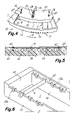
- FIG. 4 is a lower perspective view of the orientation unit of FIG. 3 ;
- FIG. 5 is a cross-sectional schematic detail of retaining means for retaining a support and/or end stop element of the orientation unit of FIG. 2 or of FIG. 3 ;
- FIG. 6 is a partial perspective view of an orientation unit according to yet another embodiment
- FIGS. 7 , 8 and 9 are front elevational, side elevational and plan views, respectively, of an aligning unit according to an embodiment
- FIG. 10 is a view similar to FIG. 9 showing another embodiment of an aligning unit.
- FIG. 11 is a rear perspective view of an orientation and aligning unit according to an embodiment.
- a machine for orienting and aligning articles according to an embodiment of the present invention is shown in a simplified manner.
- the machine comprises a plurality of orientation cavities 1 arranged in alignment on the periphery of a circular rotating structure 2 assembled to rotate about a central axis, such that the rotating structure 2 which can move said orientation cavities 1 along a closed circular path.
- Each of the orientation cavities 1 is suitable for housing one of said articles, and the machine comprises loading means for loading the articles in said orientation cavities 1 .
- the rotating structure 2 has an upper surface 22 at approximately the same level as the orientation cavities 1 and a surrounding wall 23 forming part of a stationary outer casing 24 surrounds the upper part of the rotating structure 2 and extends upwards, demarcating along with said upper surface 22 a hopper where the articles are loosely tossed in an unorganized fashion.
- the centrifugal force of the moving structure upon rotation pushes the articles towards the orientation cavities 1 .
- a plurality of aligning conduits 3 are arranged in said rotating structure 2 below the orientation cavities 1 , such that the orientation cavities 1 and the aligning conduits 3 move together.
- the orientation cavities 1 are provided with an open base through which the articles can pass, and each of said aligning conduits 3 has a funnel-shaped upper inlet 4 located below the open base of one of the orientation cavities 1 to receive an article therefrom.
- support means 5 Placed between the open base of each orientation cavity 1 and the upper inlet 4 of the respective aligning conduit 3 there are support means 5 , for example, in the form of a stationary support plane 5 , provided with an interruption in a section of said closed circular path.
- the mentioned support plane 5 acts for temporarily supporting the articles in said orientation cavities 1 and for dropping same through said interruption to the corresponding aligning conduits 3 in a predetermined location of said circular path.
- the present invention is not limited to a type of machine provided with a rotating structure 2 such as the one shown in FIG. 1 , but rather it can be applied to any machine provided with a moving arrangement 40 that can move said orientation cavities along a closed path.
- the orientation cavities and their corresponding aligning conduits can form independent bodies hingedly connected together thus forming a train that is moved along said closed path, which is arranged in a stationary structure.
- each of the orientation cavities 1 there are support and/or end stop elements 6 , 7 , 8 adapted to cooperate with parts of the article when said article falls through the open base of the orientation cavity 1 to give a predetermined orientation to the article inside the aligning conduit 3 , whatever its original position is in the orientation cavity 1 , in a manner that is well known in the state of the art.
- the articles are lightweight empty bottles and the parts thereof cooperating with the support and/or end stop elements 6 , 7 , 8 are the neck and the base.
- the machine includes deflectors or another device to finally transfer the vertically oriented containers from the aligning conduits 3 to an output conveyor 48 .
- FIG. 2 shows an embodiment of the orientation cavity 1 , having a front wall 10 and a rear wall 11 , in relation to the forward movement direction of the orientation cavity indicated by an arrow D, and an inner side wall 12 .
- the orientation cavity 1 is closed on the outer part by the mentioned outer casing 24 of the machine.
- seats or housings 20 formed on the inner side wall 12 there are seats or housings 20 in the form of a series of openings adapted to have inserted therein an inner end of a first support and/or end stop element 6 of said support and/or end stop elements 6 , 7 , 8 .
- the mentioned inner end of the first support and/or end stop element 6 comprises a material that can be magnetically attracted, and the inner side wall 12 has associated thereto retaining means in the form of a magnetic strip 14 fixed to the upper part of the inner side wall 12 , at a suitable distance from the seats or housings 20 so as to retain by magnetic attraction the first support and/or end stop element 6 installed in any of the seats or housings 20 .
- each orientation cavity 1 is connected together forming an orientation unit 30 , which is removably attached to the rotating structure 2 by conventional quick coupling means 35 , such as those described in the aforementioned patent EP-A-0578602, for example.
- FIG. 3 shows another embodiment of the orientation cavity 1 similar to that of FIG. 2 .
- the orientation cavity 1 is formed by an outer side wall 13 .
- This orientation cavity 1 incorporates several seats or housings 9 at several different positions.
- Each seat 9 has a part formed by a series of first openings 9 a formed in said outer side wall 13 and another part formed by a series of second openings 9 b formed in the inner side wall 12 .
- the first opening 9 a and the second opening 9 b of each seat 9 are mutually opposite one another.
- the first support and/or end stop element 6 is shaped as an elongated body that can pass through any one of said first openings 9 a of the outer side wall 13 and its inner end inserted in the corresponding opposing second opening 9 b of the inner side wall 12 .
- the first openings 9 a formed in the outer side wall 13 are preferably through openings whereas the second openings 9 b formed in said inner side wall 12 are blind openings, thereby limiting the insertion of the first support and/or end stop element 6 .
- the inner side wall 12 also has retaining means associated thereto in the form of a magnetic strip 14 fixed to the upper part of the inner side wall 12 , at a suitable distance from the seats or housings 20 so as to retain by magnetic attraction the first support and/or end stop element 6 installed in any of the seats 9 .
- the mentioned magnetic strip could be associated to the outer side wall 13 , or there could be two more magnetic strips installed in both inner and outer side walls 12 , 13 with an equivalent result.
- each orientation cavity 1 is connected together forming an orientation unit 32 that is removably attached to the rotating structure 2 by quick coupling means 35 .
- the seats or housings 9 , 20 are adjacent to the front wall 10 of the orientation cavity 1 , such that once the first support and/or end stop element 6 is installed, it will be more or less close to the front wall 10 , whereas formed next to the opposite rear wall 11 there is a second support and/or end stop element 7 projecting inwardly in the orientation cavity 1 .
- a side end stop 8 Arranged next to said second support and/or end stop element 7 there is a side end stop 8 configured to cooperate with the second support and/or end stop element 7 .
- a moving side plate 15 substantially parallel to the inner side wall 12 .
- This moving side plate 15 is assembled such that the position in the orientation cavity 1 can be changed, whereby at least another dimension of the orientation cavity 1 can be adapted to different articles by changing the position of the moving side plate 15 .
- the side end stop 8 is fixed to the moving side plate 15 , whereby the position can be changed along with such plate.
- FIG. 4 shows a bottom view of the orientation unit 32 of FIG. 3 and is useful for explaining the assembly of the moving side plate 15 with the understanding that a similar assembly would also be useful for the orientation unit 30 of FIG. 2 . Therefore, as shown in FIG. 4 , the moving side plate 15 projects from the lower part of the inner side wall 12 and is attached to a lower plate 25 superimposed on a lower surface of the inner side wall 12 . Formed in the mentioned lower plate 25 there are a pair of mutually parallel guide grooves 26 in which lugs 27 fixed in the lower surface of the inner side wall 12 are inserted, and a fixing groove 28 , parallel to said guide grooves 26 , through which a lock screw 29 coupled to a threaded hole formed in the lower surface of the inner side wall 12 passes.
- FIG. 5 schematically shows the assembly of the magnetic strip 14 forming part of the retaining means in the orientation units 30 , 32 described above in relation to FIGS. 2 and 3 .
- Screws 42 coupled to corresponding threaded holes 43 formed in said depression 41 of the inner side wall 12 pass through holes of the magnetic strip 14 .
- the second openings 9 b formed in said inner side wall 12 as part of the seats 9 have a longitudinal axis substantially parallel to the magnetic strip 14 and a portion of the inner wall of the second openings 9 b is very close to the surface of the depression 41 .
- the inner end of the first support and/or end stop element 6 that can be magnetically attracted, inserted in one of the second openings 9 b is very close to the magnetic strip 14 housed in the depression 41 , and therefore the first support and/or end stop element 6 is retained in position by magnetic attraction.
- the magnetic strip is fixed in a rear surface of the inner side wall 12 and the second openings 9 b have a longitudinal axis substantially perpendicular to the magnetic strip 14 .
- the inner end that can be magnetically attracted of the first support and/or end stop element 6 inserted in one of the second openings 9 b is very close to the magnetic strip 14 or in contact with same if the second openings 9 b are through openings and limited by the magnetic strip 14 .
- the orientation units 30 , 32 illustrated in FIGS. 2 and 3 also allow some variations.
- the first and second openings 9 a , 9 b forming the seats 9 could be formed next to the rear wall 11 instead of the front wall 10 , and accordingly the second support and/or end stop element 7 would be next to the front wall 10 instead of the rear wall 11 .
- the moving side plate 15 could be arranged next to the outer side wall 13 instead of the inner side wall 12 , and with an alternating guiding and fixing groove device on the lower superficies of the front and rear walls.
- each of said seats or housings 21 has a part 21 a associated to the outer side wall 13 and another part 21 b associated to the inner side wall 12 . More specifically, the several seats or housings 21 here are formed by a series of first elastic grippers 21 a arranged in said outer side wall 13 and a series of second elastic grippers 21 b arranged in said inner side wall 12 .
- the first and second elastic grippers 21 a , 21 b of each seat 21 are mutually aligned and can be formed integrally with the corresponding inner and outer side walls 12 , 13 or they can be inserts.
- the first support and/or end stop element 6 is shaped as an elongated body having an outer end that can be held in any one of said first elastic grippers 21 a of the outer side wall 13 and an inner end that can ser held in the corresponding aligned second opening 21 b of the inner side wall 12 , and the first and second elastic grippers 21 a , 21 b can elastically apply pressure on the ends of the first support and/or end stop element 6 . Therefore the first and second elastic grippers 21 a , 21 b at the same time act as seats or housings and as retaining means for the first support and/or end stop element 9 . It can therefore be observed here that the retaining means are associated to both inner and outer side walls 12 , 13 .
- FIGS. 7 , 8 and 9 show one of the aligning conduits 3 according to an embodiment of the present invention, which is formed by a front wall 16 and a rear wall 17 formed in relation to the forward movement direction of the orientation cavity indicated by an arrow D, and an inner side wall 18 .
- the front wall 16 is fixed in relation to the inner side wall 18
- the rear wall 17 is assembled such that it can be changed from position in relation to the front wall 16 .
- the inner side wall 18 includes grooves 44 through which threaded ends of rods 45 attached to the rear wall 17 and coupled to nuts 46 in the rear face of the inner side wall 18 pass.
- the mentioned nuts 46 are in the form of manual operation knobs, for example.
- the rear wall 17 which, as described, is assembled such that it can be changed from position, includes an inclined upper portion 17 a contributing to forming the mentioned funnel-shaped upper inlet 4 , and a lower portion 17 b contributing to forming the aligning conduit 3 .
- the upper portion 17 a is assembled such that the inclination thereof can be changed in relation to the lower portion 17 b .
- one of the rods 45 is attached to the upper end of the lower portion 17 b and is surrounded by a sleeve 47 attached to the lower end of the upper portion 17 a of the rear wall 17 , or vice versa.
- a relative rotation between the sleeve 47 and the rod 44 acts as a hinge between the upper portion 17 a and the lower portion 17 b of the rear wall 17 when the corresponding nut 46 is loosened. Notice the change in position of the upper and lower portions 17 a , 17 b of the rear wall can affect both their movement and their inclination.
- At least one dimension of the upper inlet 4 can be adapted to different articles by changing the inclination of said upper portion 17 a regardless of the clearance area or dimension of the aligning conduit 3 formed by the position of the lower portion 17 b of the rear wall 17 in relation to the other rear or front wall 16 , and at least one dimension of the aligning conduit 3 can be adapted to different articles by changing the position the lower portion of the rear wall 17 .
- the rear wall 17 could be a one-piece movably assembled wall instead of integrating the two upper and lower portions 17 a , 17 b .
- the rear wall could also be the fixed wall and the front wall could be the wall assembled such that the position in relation to the front wall could be changed, either in one piece or in two portions, with an equivalent result.
- the aligning conduit 3 is furthermore formed by an outer side wall 19 , which is assembled such that the position in relation to the inner side wall 18 can be changed, whereby at least another dimension of the aligning conduit 3 can be adapted to different articles by changing the position of the outer side wall 19 .
- the front side wall 16 includes grooves 51 through which threaded ends of rods 52 attached to angle brackets 53 integral with the outer side wall 19 and coupled to nuts 54 in the outer face of the front side wall 16 pass.
- the mentioned nuts 54 are in the form of manual operation knobs for example.
- each aligning conduit 3 is connected together forming an aligning unit 50 adapted to be removably attached to the rotating structure 2 by quick coupling means 55 .
- FIG. 10 shows an alternative embodiment similar to the embodiment described in relation to FIGS. 7 , 8 and 9 except in that the aligning conduit 3 does not have an outer side wall, which in this case will be provided by the stationary outer casing 24 .
- a moving plate 64 arranged next to the inner side wall 18 there is a moving plate 64 , substantially parallel to the inner side wall 18 .
- the moving plate 64 is assembled such that the position in relation to the inner side wall 18 can be changed for the purpose of adapting the other dimension of the aligning conduit 3 to different articles.
- the front side wall 16 includes grooves 61 through which threaded ends of rods 62 attached to angle brackets 63 integral with the moving plate 64 and coupled to nuts (not shown in FIG. 10 ) in the outer face of the front side wall 16 pass.
- each aligning conduit 3 is connected together forming an aligning unit 60 adapted to be removably attached to the rotating structure 2 by quick coupling means 65 .
- FIG. 11 finally shows an orientation and aligning unit 70 integrating front, rear, inner and outer walls 10 , 11 , 12 , 13 forming an orientation cavity 1 similar to the one described above in relation to FIG. 3 , and front, rear, inner and outer walls 16 , 17 , 18 , 19 forming each aligning conduit 3 similar to that described above in relation to FIGS. 7 to 9 .
- the rear wall 18 of the aligning conduit 3 extends upwards and acts as a support for the orientation cavity 1 .
- the orientation and aligning unit 70 is adapted to be removably attached to the rotating structure 2 by quick coupling means 75 . There is gap between the orientation cavity 1 and the aligning conduit 3 in which, when the orientation and aligning unit 70 is attached to the rotating structure 2 , the mentioned stationary support plane 5 , which is generally attached to the outer casing 24 , will be inserted.
- the orientation and aligning unit has front, rear and inner walls 10 , 11 , 12 forming an orientation cavity 1 similar to the one described above in relation to FIG. 2 , and front, rear and inner walls 16 , 17 , 18 forming an aligning conduit 3 similar to the one described above in relation to FIG. 10 .
- the orientation cavity 1 and the aligning conduit 3 are closed by means of the stationary outer casing 24 .
- This orientation and aligning unit is also adapted to be removably attached to the rotating structure 2 by quick coupling means.
- this invention in fact describes a different process of adaptation or adjustment according to which each of said orientation and/or aligning units of the machine will be accessed and the adaptation or adjustment is obtained by modifying in each unit (generally in a uniform or common manner for the set of units) the position of several elements forming supports, end stops or guides, also determining the chosen position of these elements in each unit an adjustment of the support, access or passage of the articles therethrough.
- This change of position involves disassembling the elements from a first position and fixing them in a second position for which purpose different assembly solutions, preferably without needing tools, are provided.
Applications Claiming Priority (5)
| Application Number | Priority Date | Filing Date | Title |
|---|---|---|---|
| ES200502279 | 2005-09-09 | ||
| ES200502279A ES2250013B1 (es) | 2005-09-09 | 2005-09-09 | Maquina para orientar y alinear articulos. |
| ESP200502279 | 2005-09-09 | ||
| PCT/ES2006/000512 WO2007028848A1 (es) | 2005-09-09 | 2006-09-08 | Máquina para orientar y alinear artículos |
| ESPCT/ES2006/000512 | 2006-09-08 |
Publications (2)
| Publication Number | Publication Date |
|---|---|
| US20080314717A1 US20080314717A1 (en) | 2008-12-25 |
| US8096403B2 true US8096403B2 (en) | 2012-01-17 |
Family
ID=36179029
Family Applications (1)
| Application Number | Title | Priority Date | Filing Date |
|---|---|---|---|
| US12/066,293 Expired - Fee Related US8096403B2 (en) | 2005-09-09 | 2006-09-08 | Machine for orienting and aligning articles |
Country Status (4)
| Country | Link |
|---|---|
| US (1) | US8096403B2 (es) |
| EP (1) | EP1932784A4 (es) |
| ES (1) | ES2250013B1 (es) |
| WO (1) | WO2007028848A1 (es) |
Cited By (12)
| Publication number | Priority date | Publication date | Assignee | Title |
|---|---|---|---|---|
| US20110048897A1 (en) * | 2008-04-11 | 2011-03-03 | Anker Andersen A/S | apparatus and method for feeding used objects |
| US20120217131A1 (en) * | 2009-11-12 | 2012-08-30 | Lorenzo Forni | Unscrambling machine for containers and relative process |
| US9567162B2 (en) | 2015-02-20 | 2017-02-14 | Jaime Martí Sala | Rotary conveyor with suction and change of pitch for transferring containers |
| US9586768B2 (en) | 2015-04-10 | 2017-03-07 | Jaime Martí Sala | Apparatus for positioning containers |
| US9989342B1 (en) * | 2016-12-07 | 2018-06-05 | James N. Lougeay | Case orientation device |
| EP3579203A1 (de) * | 2018-06-05 | 2019-12-11 | Wincor Nixdorf International GmbH | Leergut-leitelement, leergut-handhabungseinrichtung und leergut-rücknahmesystem |
| US10533817B1 (en) * | 2017-06-21 | 2020-01-14 | Vista Outdoor Operations Llc | Electric magazine loader |
| US10907945B2 (en) * | 2019-01-05 | 2021-02-02 | Gary Lee Puchosic | Bullet loader |
| US11021286B1 (en) * | 2021-01-05 | 2021-06-01 | Performance Feeders, Inc. | Receptacle feeding system |
| US11022390B2 (en) * | 2014-01-14 | 2021-06-01 | Magpump, Llc | Ammunition management device and method |
| US11118854B2 (en) | 2018-01-23 | 2021-09-14 | Magpump, Llc | Ammunition movement system and method for firearm magazine loaders |
| US11390467B2 (en) * | 2018-05-04 | 2022-07-19 | Traktech Contruccions Mecaniques, S.L. | Container-orienting device and positioning machine supporting same |
Families Citing this family (7)
| Publication number | Priority date | Publication date | Assignee | Title |
|---|---|---|---|---|
| IT1393912B1 (it) * | 2009-04-30 | 2012-05-17 | O Za F S R L | Macchina riordinatrice con sistema di aggancio rapido degli alveoli di selezione |
| KR101871840B1 (ko) * | 2011-01-14 | 2018-06-27 | 가부시키가이샤 유야마 세이사쿠쇼 | 정제 카세트 |
| DE102012106263A1 (de) * | 2012-07-12 | 2014-01-16 | Krones Ag | Vorrichtung zum Führen von Behältern |
| ITUB20153464A1 (it) * | 2015-09-08 | 2017-03-08 | Lanfranchi Srl | Dispositivo ordinatore provvisto di sistema per il cambio formato dei telai separatori |
| CN105438781A (zh) * | 2015-12-09 | 2016-03-30 | 重庆胜波科技开发有限公司 | 用于转子的定向调整装置 |
| CN107673042B (zh) * | 2017-10-23 | 2024-04-16 | 常州汇拓科技有限公司 | 理盖器用工位板 |
| US20230015679A1 (en) * | 2021-07-09 | 2023-01-19 | Greg Schombert | Scallop Feeder Bowl and Delivery System for Necked Bottles and like objects |
Citations (14)
| Publication number | Priority date | Publication date | Assignee | Title |
|---|---|---|---|---|
| US3295659A (en) | 1965-03-02 | 1967-01-03 | Samuel S Aidlin | Hopper-type feeding and orienting device for bottles or the like |
| US3662872A (en) * | 1969-07-10 | 1972-05-16 | Colgate Palmolive Co | Apparatus for orienting and feeding articles |
| GB1558379A (en) | 1976-12-14 | 1979-12-28 | Hoehn J W | Apparatus for orientating objects |
| EP0065866A1 (en) | 1981-05-18 | 1982-12-01 | Aylesbury Automation Limited | Apparatus for orientating articles such as bottles, and orientating means therefor |
| EP0578602A1 (en) | 1992-07-07 | 1994-01-12 | Jaime Marti Sala | Machine for automatically positioning and aligning containers |
| ES2049601A2 (es) | 1991-10-03 | 1994-04-16 | Marti Sala | Maquina para el posicionado vertical y alineacion de recipientes con adaptacion automatica al formato de los mismos. |
| ES2087003A2 (es) | 1992-07-07 | 1996-07-01 | Sala Jaime Marti | Mejoras en la patente principal n 9201508 por: "maquina para posicionar y alinear recipientes diversos". |
| WO1999059904A1 (es) | 1998-05-21 | 1999-11-25 | Jaime Marti Sala | Maquina regulable para la orientacion vertical y alineacion de recipientes vacios |
| US6065587A (en) * | 1996-12-20 | 2000-05-23 | Schindel; Hugo | Apparatus for single file transporting of bottles and molded articles |
| WO2001040084A1 (es) | 1999-12-03 | 2001-06-07 | Jaime Marti Sala | Maquina automatica, adaptable, para orientacion y entrega alineada de articulos huecos ligeros |
| ES2163957A1 (es) | 1998-10-19 | 2002-02-01 | Bottle Automation Mfg S A | Elemento separador de ajuste automatico. |
| US6557691B2 (en) * | 2000-03-08 | 2003-05-06 | Ronchi Mario S.P.A. | Device for container rearranging machines, provided with automatic means for directing and dropping the container received |
| WO2003078284A1 (en) | 2002-03-20 | 2003-09-25 | Lanfranchi S.R.L. | Device for automatically adjusting means for vertically directing and aligning plastic containers in an directing-aligning machine |
| US7374032B2 (en) * | 2002-10-03 | 2008-05-20 | Alex Marti Mercade | Machine for righting and aligning articles using drop chutes comprising multiple compartments |
-
2005
- 2005-09-09 ES ES200502279A patent/ES2250013B1/es not_active Expired - Fee Related
-
2006
- 2006-09-08 EP EP06807944A patent/EP1932784A4/en not_active Withdrawn
- 2006-09-08 US US12/066,293 patent/US8096403B2/en not_active Expired - Fee Related
- 2006-09-08 WO PCT/ES2006/000512 patent/WO2007028848A1/es active Application Filing
Patent Citations (16)
| Publication number | Priority date | Publication date | Assignee | Title |
|---|---|---|---|---|
| US3295659A (en) | 1965-03-02 | 1967-01-03 | Samuel S Aidlin | Hopper-type feeding and orienting device for bottles or the like |
| US3662872A (en) * | 1969-07-10 | 1972-05-16 | Colgate Palmolive Co | Apparatus for orienting and feeding articles |
| GB1558379A (en) | 1976-12-14 | 1979-12-28 | Hoehn J W | Apparatus for orientating objects |
| EP0065866A1 (en) | 1981-05-18 | 1982-12-01 | Aylesbury Automation Limited | Apparatus for orientating articles such as bottles, and orientating means therefor |
| ES2049601A2 (es) | 1991-10-03 | 1994-04-16 | Marti Sala | Maquina para el posicionado vertical y alineacion de recipientes con adaptacion automatica al formato de los mismos. |
| EP0578602A1 (en) | 1992-07-07 | 1994-01-12 | Jaime Marti Sala | Machine for automatically positioning and aligning containers |
| US5415322A (en) * | 1992-07-07 | 1995-05-16 | Sala; Jaime M. | Machine for automatically positioning and aligning containers |
| ES2087003A2 (es) | 1992-07-07 | 1996-07-01 | Sala Jaime Marti | Mejoras en la patente principal n 9201508 por: "maquina para posicionar y alinear recipientes diversos". |
| US6065587A (en) * | 1996-12-20 | 2000-05-23 | Schindel; Hugo | Apparatus for single file transporting of bottles and molded articles |
| WO1999059904A1 (es) | 1998-05-21 | 1999-11-25 | Jaime Marti Sala | Maquina regulable para la orientacion vertical y alineacion de recipientes vacios |
| US6435333B1 (en) * | 1998-05-21 | 2002-08-20 | Jaime Marti Sala | Adjustable unit for the unscrambling and lined up delivery of empty containers |
| ES2163957A1 (es) | 1998-10-19 | 2002-02-01 | Bottle Automation Mfg S A | Elemento separador de ajuste automatico. |
| WO2001040084A1 (es) | 1999-12-03 | 2001-06-07 | Jaime Marti Sala | Maquina automatica, adaptable, para orientacion y entrega alineada de articulos huecos ligeros |
| US6557691B2 (en) * | 2000-03-08 | 2003-05-06 | Ronchi Mario S.P.A. | Device for container rearranging machines, provided with automatic means for directing and dropping the container received |
| WO2003078284A1 (en) | 2002-03-20 | 2003-09-25 | Lanfranchi S.R.L. | Device for automatically adjusting means for vertically directing and aligning plastic containers in an directing-aligning machine |
| US7374032B2 (en) * | 2002-10-03 | 2008-05-20 | Alex Marti Mercade | Machine for righting and aligning articles using drop chutes comprising multiple compartments |
Non-Patent Citations (1)
| Title |
|---|
| International Search Report for PCT International Application No. PCT/ES2006/000512 mailed Jan. 9, 2007. |
Cited By (15)
| Publication number | Priority date | Publication date | Assignee | Title |
|---|---|---|---|---|
| US8522955B2 (en) * | 2008-04-11 | 2013-09-03 | Anker Andersen A/S | Apparatus and method for feeding used objects |
| US20110048897A1 (en) * | 2008-04-11 | 2011-03-03 | Anker Andersen A/S | apparatus and method for feeding used objects |
| US20120217131A1 (en) * | 2009-11-12 | 2012-08-30 | Lorenzo Forni | Unscrambling machine for containers and relative process |
| US8701865B2 (en) * | 2009-11-12 | 2014-04-22 | Lorenzo Forni | Unscrambling machine for containers and relative process |
| US11022390B2 (en) * | 2014-01-14 | 2021-06-01 | Magpump, Llc | Ammunition management device and method |
| US9567162B2 (en) | 2015-02-20 | 2017-02-14 | Jaime Martí Sala | Rotary conveyor with suction and change of pitch for transferring containers |
| US9586768B2 (en) | 2015-04-10 | 2017-03-07 | Jaime Martí Sala | Apparatus for positioning containers |
| US9989342B1 (en) * | 2016-12-07 | 2018-06-05 | James N. Lougeay | Case orientation device |
| US10533817B1 (en) * | 2017-06-21 | 2020-01-14 | Vista Outdoor Operations Llc | Electric magazine loader |
| US11118854B2 (en) | 2018-01-23 | 2021-09-14 | Magpump, Llc | Ammunition movement system and method for firearm magazine loaders |
| US11390467B2 (en) * | 2018-05-04 | 2022-07-19 | Traktech Contruccions Mecaniques, S.L. | Container-orienting device and positioning machine supporting same |
| EP3579203A1 (de) * | 2018-06-05 | 2019-12-11 | Wincor Nixdorf International GmbH | Leergut-leitelement, leergut-handhabungseinrichtung und leergut-rücknahmesystem |
| US10907945B2 (en) * | 2019-01-05 | 2021-02-02 | Gary Lee Puchosic | Bullet loader |
| US11021286B1 (en) * | 2021-01-05 | 2021-06-01 | Performance Feeders, Inc. | Receptacle feeding system |
| US11511898B1 (en) * | 2021-01-05 | 2022-11-29 | Performance Feeders, Inc. | Receptacle feeding system |
Also Published As
| Publication number | Publication date |
|---|---|
| WO2007028848A1 (es) | 2007-03-15 |
| EP1932784A4 (en) | 2012-01-04 |
| ES2250013A1 (es) | 2006-04-01 |
| EP1932784A1 (en) | 2008-06-18 |
| ES2250013B1 (es) | 2006-12-01 |
| US20080314717A1 (en) | 2008-12-25 |
Similar Documents
| Publication | Publication Date | Title |
|---|---|---|
| US8096403B2 (en) | Machine for orienting and aligning articles | |
| JP4132670B2 (ja) | 空容器の再配列及び整列配給のための調節可能なユニット | |
| AU2003279420B2 (en) | Machine for supplying/dispensing containers and long articles in general | |
| CN101370635B (zh) | 用于多成分注塑模制的传送系统 | |
| KR101883513B1 (ko) | 비지향된 물체용 공급장치 | |
| ITPD20080331A1 (it) | Apparecchiatura per il trasferimento di contenitori | |
| US20090101476A1 (en) | Methods and apparatuses for controlled discharge | |
| US7040489B2 (en) | Object orienting and sorting apparatus | |
| US8714958B2 (en) | Blow mould assembly | |
| CN102112285B (zh) | 用于吹塑塑料容器,尤其是用于吹塑瓶子的设备的模制单元 | |
| US20200391280A1 (en) | Method and apparatus for forming sand molds via top and bottom pneumatic sand filling perpendicular to the pattern plate | |
| CN110194359A (zh) | 一种全自动整理输送设备 | |
| US10255741B2 (en) | Chip sorting devices and related assemblies, components and methods | |
| KR20150076255A (ko) | 피봇가능하게 장착된 상부 및 하부 케이싱을 갖는 핀치 밸브 | |
| CN103502119A (zh) | 具有闸门装置的输送系统 | |
| US20200039761A1 (en) | Carrying apparatus and cam control shaft for gripping devices | |
| US20090098235A1 (en) | Stretching rod holding arrangement | |
| CN100513135C (zh) | 拉伸棒可拆卸地固定在滑套上所用的设置 | |
| US20080296127A1 (en) | Article-Positioning Machine | |
| KR100430809B1 (ko) | 너트 공급장치 | |
| US6827199B1 (en) | Article transporting and escapement device | |
| JP4995624B2 (ja) | 集合ホッパ | |
| SU1349953A1 (ru) | Автомат дл сборки болтов с шайбами | |
| KR102512630B1 (ko) | 경첩 자동조립장치 | |
| EP3798159B1 (en) | Container-orienting device and positioning machine supporting same |
Legal Events
| Date | Code | Title | Description |
|---|---|---|---|
| REMI | Maintenance fee reminder mailed | ||
| LAPS | Lapse for failure to pay maintenance fees | ||
| STCH | Information on status: patent discontinuation |
Free format text: PATENT EXPIRED DUE TO NONPAYMENT OF MAINTENANCE FEES UNDER 37 CFR 1.362 |
|
| FP | Lapsed due to failure to pay maintenance fee |
Effective date: 20160117 |