US809132A - Ticket-holder. - Google Patents
Ticket-holder. Download PDFInfo
- Publication number
- US809132A US809132A US27248305A US1905272483A US809132A US 809132 A US809132 A US 809132A US 27248305 A US27248305 A US 27248305A US 1905272483 A US1905272483 A US 1905272483A US 809132 A US809132 A US 809132A
- Authority
- US
- United States
- Prior art keywords
- ticket
- holder
- bar
- cross
- pin
- Prior art date
- Legal status (The legal status is an assumption and is not a legal conclusion. Google has not performed a legal analysis and makes no representation as to the accuracy of the status listed.)
- Expired - Lifetime
Links
Images
Classifications
-
- G—PHYSICS
- G09—EDUCATION; CRYPTOGRAPHY; DISPLAY; ADVERTISING; SEALS
- G09F—DISPLAYING; ADVERTISING; SIGNS; LABELS OR NAME-PLATES; SEALS
- G09F3/00—Labels, tag tickets, or similar identification or indication means; Seals; Postage or like stamps
Definitions
- the object of my invention is to provide a holder whereby tickets containing the proper information regarding dress good fabrics rolled about a board or the like may be readily attached or detached and properly supported in position where they can be readily viewed.
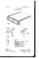
- Figure 1 is a perspective view showing a roll of fabric with the rolling-board and series of ticket-holders made in accordance with my invention and secured at the outer end and the ticket passing through said holders.
- Fig. 2 is a perspective view of one embodiment of my invention.
- Fig. 3 is an enlarged view showing the end of the pin or nail of a modified construction, and
- Figs. 4 and 5 show further modifications embracing the same general features of construction, Fig. 5 showing additionally a section of the rollingboard having a molded end and the nail or pin having a flattened surface inserted therein, showing the method of fixing any of the forms on the end of the board and the means of preventing the nail used with any of the forms from turning.
- the device embodying my invention essentially consists of a nail, pin, or the like, such as 1, Figs. 2 and 4, which provides means for readily attaching the holder to the end of the rolling-board, as shown in Figs. 1 and 5, and a laterally-expanded slotted head 2, the slot in the head being both parallel and transverse with the base of the head.
- My invention also contemplates the use of a spring attachment forming a part of the head, whereby the ticket is forced against the base of the head and held against inadvertent displacement.
- the head comprises the lateral base-plate 3, the end uprights 4, and the top cross-piece 5, which parts form the approximately rectangular slot extending both parallel with and transversely to the direction of the base-plate.
- the top cross-piece (which may be made integral with or otherwise secured to the end uprights) is formed with a downward bend, so as to give it a spring.
- This holder is, as aforesaid, inserted by forcing the pin or nail into the end of the rolling-board and preferably so that the plate bears against the upright edge of said board.
- these holders may be secured to the end of the rolling-board. If it is intended that one be used, I prefer that the pin or nail be flattened for a portion of its length, as at 6 in Figs. 3 and 5, so as to prevent the holder from turning when but one is used.
- the ticket 7 is then passed through the holder, the spring cross bar pressing the same with suflicient force against the bottom cross-bar to retain it permanently in place, or, if it is desired, two or three or any particular number of the holders may be employed, as illustrated in Fig. 1, in which event the use of a flattened pin or nail is not necessary, although it may be advantageous to use and flatten the nail under these conditions to prevent turning of the holder as well as facilitating its insertion into the rollingboard.
- the holders When used as shown in Fig. 1, the holders divide the ticket into sections, which may be suitably inscribed.
- the same inscription may be used on both sides of the intermediate holder, upside down relative to each other, so that the inscription can be read regardless of the position of the roll of material on the store-shelves.
- Fig. 4 I have illustrated a modification in which the top cross-bar is made in two sec tions, each section comprising an upwardly and downwardly curved spring-clip 8, their inner ends being supported a suitable dis tance apart.
- Fig. 5 I have illustrated a further modification.
- the roll-boards are made with a molded or rounded edge 9.
- I have rounded the lower cross-bar, so as to have it correspond substantially with the curved edge of the board, and have formed the top cross-bar with an intermediate and downward projection 10, forming a spring which bears upon the outer face of the ticket, as before described.
- prising a pin and a laterally-expanded head comprising a bottom cross-bar, side uprights, and to cross-bar, the cross-bars and uprights orming a slot extending transversely through the head parallel with the bottom cross-bar, substantially as described.
- An article of the class described comprising a pin, and a laterally-expanded head comprising a bottom cross-bar, a top crossbar over the bottom bar, the said bars being so secured so as to form a slot between, said top bar being depressed so as to act as a spring.
Landscapes
- Physics & Mathematics (AREA)
- General Physics & Mathematics (AREA)
- Engineering & Computer Science (AREA)
- Theoretical Computer Science (AREA)
- Credit Cards Or The Like (AREA)
- Devices For Checking Fares Or Tickets At Control Points (AREA)
Description
N0. 809,132. PATENTED JAN. 2, 1906.
N, A. PLANOIGH. TICKET HOLDER.
IIIIIIIIIII T FILED AUG. 3, 1905.
g $51 71/114cltkomi v L 7 UNITED STATES PATENT OFFICE.
Specification of Letters Patent.
Patented Jan. 2, 1906.
Application filed August 3,1905. Serial No. 272,483.
1'0 03% whom it may concern.-
Be it known that I, NICHOLAS A. PLAN- oIoH, a citizen of the United States, residing in the city of San Francisco, county of San Francisco, and State of California, (whose post-office address is 440 Eddy street, in said city,) have made certain new and useful Improvements in Ticket-Holders, of which the following is a specification.
The object of my invention is to provide a holder whereby tickets containing the proper information regarding dress good fabrics rolled about a board or the like may be readily attached or detached and properly supported in position where they can be readily viewed.
The object of my invention therefore consists in a device substantially as hereinafter described, and further pointed out in the claims. I
In the drawings forming part of this specification, Figure 1 is a perspective view showing a roll of fabric with the rolling-board and series of ticket-holders made in accordance with my invention and secured at the outer end and the ticket passing through said holders. Fig. 2 is a perspective view of one embodiment of my invention. Fig. 3 is an enlarged view showing the end of the pin or nail of a modified construction, and Figs. 4 and 5 show further modifications embracing the same general features of construction, Fig. 5 showing additionally a section of the rollingboard having a molded end and the nail or pin having a flattened surface inserted therein, showing the method of fixing any of the forms on the end of the board and the means of preventing the nail used with any of the forms from turning.
Similar reference characters indicate like parts throughout the several views.
The device embodying my invention essentially consists of a nail, pin, or the like, such as 1, Figs. 2 and 4, which provides means for readily attaching the holder to the end of the rolling-board, as shown in Figs. 1 and 5, and a laterally-expanded slotted head 2, the slot in the head being both parallel and transverse with the base of the head. My invention also contemplates the use of a spring attachment forming a part of the head, whereby the ticket is forced against the base of the head and held against inadvertent displacement.
As embodied in Figs. 1 and 2, the head comprises the lateral base-plate 3, the end uprights 4, and the top cross-piece 5, which parts form the approximately rectangular slot extending both parallel with and transversely to the direction of the base-plate. The top cross-piece (which may be made integral with or otherwise secured to the end uprights) is formed with a downward bend, so as to give it a spring.
This holder is, as aforesaid, inserted by forcing the pin or nail into the end of the rolling-board and preferably so that the plate bears against the upright edge of said board. One or more of these holders may be secured to the end of the rolling-board. If it is intended that one be used, I prefer that the pin or nail be flattened for a portion of its length, as at 6 in Figs. 3 and 5, so as to prevent the holder from turning when but one is used. The ticket 7 is then passed through the holder, the spring cross bar pressing the same with suflicient force against the bottom cross-bar to retain it permanently in place, or, if it is desired, two or three or any particular number of the holders may be employed, as illustrated in Fig. 1, in which event the use of a flattened pin or nail is not necessary, although it may be advantageous to use and flatten the nail under these conditions to prevent turning of the holder as well as facilitating its insertion into the rollingboard.
When used as shown in Fig. 1, the holders divide the ticket into sections, which may be suitably inscribed. The same inscription may be used on both sides of the intermediate holder, upside down relative to each other, so that the inscription can be read regardless of the position of the roll of material on the store-shelves.
In Fig. 4 I have illustrated a modification in which the top cross-bar is made in two sec tions, each section comprising an upwardly and downwardly curved spring-clip 8, their inner ends being supported a suitable dis tance apart.
In Fig. 5 I have illustrated a further modification. In many cases the roll-boards are made with a molded or rounded edge 9. To fit the ends of such rolling boards, I have rounded the lower cross-bar, so as to have it correspond substantially with the curved edge of the board, and have formed the top cross-bar with an intermediate and downward projection 10, forming a spring which bears upon the outer face of the ticket, as before described.
prising a pin and a laterally-expanded head comprising a bottom cross-bar, side uprights, and to cross-bar, the cross-bars and uprights orming a slot extending transversely through the head parallel with the bottom cross-bar, substantially as described.
2. An article of the class described comprising a pin, and a laterally-expanded head comprising a bottom cross-bar, a top crossbar over the bottom bar, the said bars being so secured so as to form a slot between, said top bar being depressed so as to act as a spring.
3.'An article of the class described comprising a pin, provided with a flat surface to prevent the same from turning when inserted in place, and a laterally-expanded head comprising bottom and top cross-bars, side up rights, the cross-bar and uprights forming a slot extending parallel with the bottom crossbar.
Signed this 2d day of August, 1905.
NICHOLAS A. PLANCICH. Witnesses:
L. MARIE JURY, CHAS. G. HENsLEY.
Priority Applications (1)
| Application Number | Priority Date | Filing Date | Title |
|---|---|---|---|
| US27248305A US809132A (en) | 1905-08-03 | 1905-08-03 | Ticket-holder. |
Applications Claiming Priority (1)
| Application Number | Priority Date | Filing Date | Title |
|---|---|---|---|
| US27248305A US809132A (en) | 1905-08-03 | 1905-08-03 | Ticket-holder. |
Publications (1)
| Publication Number | Publication Date |
|---|---|
| US809132A true US809132A (en) | 1906-01-02 |
Family
ID=2877613
Family Applications (1)
| Application Number | Title | Priority Date | Filing Date |
|---|---|---|---|
| US27248305A Expired - Lifetime US809132A (en) | 1905-08-03 | 1905-08-03 | Ticket-holder. |
Country Status (1)
| Country | Link |
|---|---|
| US (1) | US809132A (en) |
-
1905
- 1905-08-03 US US27248305A patent/US809132A/en not_active Expired - Lifetime
Similar Documents
| Publication | Publication Date | Title |
|---|---|---|
| US1417325A (en) | Ticket holder | |
| US809132A (en) | Ticket-holder. | |
| US917914A (en) | Bottle and ticket holder. | |
| US334981A (en) | Label | |
| US601144A (en) | Paper-delivering device | |
| US934220A (en) | Ticket-holder. | |
| US774495A (en) | Post-card exhibitor. | |
| US1540556A (en) | Card holder | |
| US811489A (en) | Card-case. | |
| US1208533A (en) | Stamp-holder. | |
| US1101826A (en) | Memorandum-indicator. | |
| US1178738A (en) | Button. | |
| US897064A (en) | Pen and pencil holder. | |
| US889844A (en) | Sheet-metal shelf. | |
| US323598A (en) | Isaum | |
| US508046A (en) | Ticket-case | |
| US1132097A (en) | Sign-board. | |
| US795240A (en) | Pin-ticket for fabrics, clothing, &c. | |
| US808422A (en) | Lettering-guide. | |
| US712952A (en) | Pin. | |
| US542128A (en) | Check-pad | |
| US1116172A (en) | Button-mold holder. | |
| US528196A (en) | O g o o o o o | |
| US430730A (en) | Josephine de young and sarah andrews | |
| US416796A (en) | Clasp and tag |