US8079635B2 - Deformable cross-car beam system for side impact protection - Google Patents
Deformable cross-car beam system for side impact protection Download PDFInfo
- Publication number
- US8079635B2 US8079635B2 US12/732,033 US73203310A US8079635B2 US 8079635 B2 US8079635 B2 US 8079635B2 US 73203310 A US73203310 A US 73203310A US 8079635 B2 US8079635 B2 US 8079635B2
- Authority
- US
- United States
- Prior art keywords
- cross
- deformable
- vehicle
- side impact
- car beam
- Prior art date
- Legal status (The legal status is an assumption and is not a legal conclusion. Google has not performed a legal analysis and makes no representation as to the accuracy of the status listed.)
- Expired - Fee Related
Links
Images


Classifications
-
- B—PERFORMING OPERATIONS; TRANSPORTING
- B62—LAND VEHICLES FOR TRAVELLING OTHERWISE THAN ON RAILS
- B62D—MOTOR VEHICLES; TRAILERS
- B62D21/00—Understructures, i.e. chassis frame on which a vehicle body may be mounted
- B62D21/15—Understructures, i.e. chassis frame on which a vehicle body may be mounted having impact absorbing means, e.g. a frame designed to permanently or temporarily change shape or dimension upon impact with another body
- B62D21/157—Understructures, i.e. chassis frame on which a vehicle body may be mounted having impact absorbing means, e.g. a frame designed to permanently or temporarily change shape or dimension upon impact with another body for side impacts
-
- B—PERFORMING OPERATIONS; TRANSPORTING
- B60—VEHICLES IN GENERAL
- B60N—SEATS SPECIALLY ADAPTED FOR VEHICLES; VEHICLE PASSENGER ACCOMMODATION NOT OTHERWISE PROVIDED FOR
- B60N2/00—Seats specially adapted for vehicles; Arrangement or mounting of seats in vehicles
- B60N2/24—Seats specially adapted for vehicles; Arrangement or mounting of seats in vehicles for particular purposes or particular vehicles
- B60N2/42—Seats specially adapted for vehicles; Arrangement or mounting of seats in vehicles for particular purposes or particular vehicles the seat constructed to protect the occupant from the effect of abnormal g-forces, e.g. crash or safety seats
- B60N2/4207—Seats specially adapted for vehicles; Arrangement or mounting of seats in vehicles for particular purposes or particular vehicles the seat constructed to protect the occupant from the effect of abnormal g-forces, e.g. crash or safety seats characterised by the direction of the g-forces
- B60N2/4235—Seats specially adapted for vehicles; Arrangement or mounting of seats in vehicles for particular purposes or particular vehicles the seat constructed to protect the occupant from the effect of abnormal g-forces, e.g. crash or safety seats characterised by the direction of the g-forces transversal
-
- B—PERFORMING OPERATIONS; TRANSPORTING
- B60—VEHICLES IN GENERAL
- B60N—SEATS SPECIALLY ADAPTED FOR VEHICLES; VEHICLE PASSENGER ACCOMMODATION NOT OTHERWISE PROVIDED FOR
- B60N2/00—Seats specially adapted for vehicles; Arrangement or mounting of seats in vehicles
- B60N2/24—Seats specially adapted for vehicles; Arrangement or mounting of seats in vehicles for particular purposes or particular vehicles
- B60N2/42—Seats specially adapted for vehicles; Arrangement or mounting of seats in vehicles for particular purposes or particular vehicles the seat constructed to protect the occupant from the effect of abnormal g-forces, e.g. crash or safety seats
- B60N2/427—Seats or parts thereof displaced during a crash
- B60N2/42727—Seats or parts thereof displaced during a crash involving substantially rigid displacement
- B60N2/42736—Seats or parts thereof displaced during a crash involving substantially rigid displacement of the whole seat
-
- B—PERFORMING OPERATIONS; TRANSPORTING
- B62—LAND VEHICLES FOR TRAVELLING OTHERWISE THAN ON RAILS
- B62D—MOTOR VEHICLES; TRAILERS
- B62D21/00—Understructures, i.e. chassis frame on which a vehicle body may be mounted
- B62D21/08—Understructures, i.e. chassis frame on which a vehicle body may be mounted built up with interlaced cross members
-
- B—PERFORMING OPERATIONS; TRANSPORTING
- B62—LAND VEHICLES FOR TRAVELLING OTHERWISE THAN ON RAILS
- B62D—MOTOR VEHICLES; TRAILERS
- B62D25/00—Superstructure or monocoque structure sub-units; Parts or details thereof not otherwise provided for
- B62D25/20—Floors or bottom sub-units
- B62D25/2009—Floors or bottom sub-units in connection with other superstructure subunits
- B62D25/2036—Floors or bottom sub-units in connection with other superstructure subunits the subunits being side panels, sills or pillars
Definitions
- the present invention relates generally to side impact protection systems and methods for automobiles or other vehicles and, more particularly, to systems and methods utilizing a cross-car beam extending between side structures that is deformable to facilitate passenger protection during vehicle side impact collisions.
- a deformable cross bar assembly includes first and second co-extensive rigid side portions and a deformable co-extensive central portion or “crush-can” portion coupled between the side portions.
- the deformable cross bar assembly is joined to the vehicle side structures.
- the deformable center portion is designed to deform at axial cross car impact forces or loads that are sustainable without deformation by the side portions.
- a deformable cross-car beam includes multiple tunable deformation zones along its length using changes in surface geometry and/or changes in material to initiate controlled deformation under a axial cross car impact force or load.
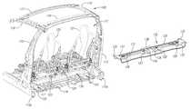
- FIG. 1 is a rear perspective view of a partial vehicle body structure with a deformable cross-car beam system for side impact protection.
- FIG. 1A is a perspective view of a deformable cross-car beam shown in FIG. 1 .
- FIG. 2 is another rear perspective view of the partial vehicle body structure with a deformable cross-car beam system shown in FIG. 1 .
- FIGS. 3 and 3A are perspective views of the deformable cross-car beam system and deformable cross-car beam shown in FIGS. 1 and 1A following a side impact event.
- FIG. 4 provides before and after side impact event perspective views of the deformable cross-car beam system shown in FIG. 1 .
- FIG. 5A through D show before and after side impact event plan views of the deformable cross-car beam tube shown in FIG. 1A .
- FIGS. 6 and 6A are perspective views of the deformable cross-car beam system and deformable cross-car beam shown in FIGS. 1 and 1A following an IIHS side impact event.
- FIGS. 7 and 7A are perspective views of the deformable cross-car beam system and deformable cross-car beam shown in FIGS. 1 and 1A following a FMVSS214 dynamic side impact event.
- FIGS. 8 and 8A are perspective views of the deformable cross-car beam system and deformable cross-car beam shown in FIGS. 1 and 1A following an oblique pole side impact event.
- FIG. 9 is a rear perspective view of another embodiment of a partial vehicle body structure with a deformable cross-car beam system for side impact protection.
- FIG. 10 is a perspective view of a deformable cross-car beam shown in FIG. 9 .
- FIGS. 11A and 11B are plan views of cross-sectional profile shapes of the deformable cross-car beam shown in FIGS. 10 and 11 .
- FIGS. 12 and 13 are perspective views of the deformable cross-car beam system and deformable cross-car beam shown in FIGS. 9 and 10 following a side impact event.
- the various embodiments and examples provided herein are generally directed to a deformable cross-car beam system for side impact protection and more particularly to a system which increases the survival space between the vehicle side structure and a vehicle passenger located in the vehicle passenger compartment while maintaining reasonable vehicle deceleration levels.
- Side impact events tend to cause intrusion of the vehicle's side structure towards a passenger located in the passenger compartment while accelerating the passenger outboard towards the deforming structure causing serious injuries to the passenger. Therefore, decoupling the passenger's deceleration from the intruding structure will allow for an increased gap between the vehicle structure and the passenger, providing an additional level of safety for the passenger.
- the embodiments described herein accomplish this decoupling by attaching the rear of the seat structure assemblies to a cross-car beam that is deformable at one or more locations along its length under an axial cross-car impact force or load.
- conventional cross-car beams perform a different function in passenger safety.
- Conventional cross-car beams serve as reinforcing members between opposing “B” pillars or side structures, increasing the axial stiffness of the vehicle.
- the function of the deformable cross-car beams of the embodiments provided herein is completely different.
- the purpose of the deformable cross-car beams described herein is to increase the survival space between the vehicle side structure and the passenger while maintaining reasonable vehicle deceleration and intrusion levels. This is achieved by deforming the cross-car beam at one or more locations along its length, allowing for the decoupling of the reinforcement feature from the motion of the occupant away from the deforming side structure.
- FIGS. 1 , 1 A and 2 a preferred embodiment of a deformable cross-car beam system including a deformable tube 30 assembly is illustrated in FIGS. 1 , 1 A and 2 .
- FIGS. 1 and 2 provide a rear perspective view of a partial body structure 10 or partial BIW defining a passenger compartment 11 .
- the passenger compartment 11 is defined by opposing vertical side structures or vehicle B-pillars 12 and 13 extending from outer frame rails 15 a and 15 b of an under body structure coupled, a floor pan 14 coupled to and extending between outer frame rails 15 a and 15 b , opposing roof side rails 18 and 19 coupled to and extending from the B pillars 12 and 13 , and a roof cross-bar 16 coupled to the roof side rails 18 and 19 at the B-pillars 12 and 13 and extending there between.
- Left and right seat structure assemblies 20 and 21 are positioned within the passenger compartment.
- the deformable tube assembly 30 which as shown in more detail in FIG. 1A , includes first and second co-extensive rigid side portions 32 and 36 and a deformable co-extensive central portion 34 or “crush-can” portion coupled between the side portions 32 and 36 .
- the tube assembly 30 is joined to the vehicle BIW 10 at two locations on the inner structures of opposing B-pillars 12 and 13 using attachment flanges 35 and 33 and two points on the vehicle floor pan 14 using attachment brackets 38 and 37 .
- the tube 30 is designed to provide B-pillar 12 and 13 attachment, rear seat structure assembly attachment at adjustment rails 22 and 23 , and a deformable center portion 34 that deforms at axial cross car crash forces that are sustainable without deformation by the side portions 32 and 36 .
- this pre-determined deformation allows for the seat 20 to move inboard in a direction M away from the intruding vehicle side structure 12 during a side impact crash event.
- This enables an increased gap (survival space) 11 A within the passenger compartment between the intruding structure 12 and the passenger in the seat 20 within the passenger compartment 11 .
- Attachment brackets 38 and 37 which extend from the tube 30 to the vehicle's floor pan 14 are designed to allow axial cross car motion while restricting vertical motion.
- FIGS. 5A through D the tube assembly 30 is illustrated in its intact, before impact configuration and its after impact, crushed configuration with the center portion 34 deformed from IIHS, FMVSS214 dynamic, and oblique pole type side impact events.
- FIGS. 6 through 8A the vehicle body structure 10 and tube assembly 30 are illustrated following IIHS, FMVSS214 dynamic, and oblique pole type side impact events.
- the tube 30 is designed to absorb pressure from any type of accident that exerts pressure from either side on the tube assembly 30 .
- FIGS. 5B through 8A shows compression of the crush can 34 upon external pressure exerted from the left side of the vehicle body structure 10 . If there was external pressure from the right side of the vehicle body structure, the image would be mirrored.
- FIGS. 6 and 7 show external pressure from a 90 degree angle.
- FIG. 8 shows external pressure at a lesser angle, e.g., as if the vehicle slid into a telephone pole at an oblique angle.
- the “after impact” angle of the side portions, in these instance the left side portion 32 , of the tube 30 is a consequence of the angle at which the vehicle absorbed pressure.
- the side bars 32 and 36 are not limited to move in a certain way, just in response to compression of the crush can 34 .
- the crush can is preferably approximately 100 mm wide and can preferably withstand compression in a range of approximately 15-20%.
- the crush can or collapsible center portion 34 of the tube 30 assembly is formed from a material, such as steel, composite or the like, that is intended to crush under loads substantially lower than loads sustainable without deformation by the side portion tubes 32 and 36 extending from the B-pillars 12 and 13 to the center portion 34 of the tube 30 assembly.
- the center deformable portion 34 of the tube 30 assembly is preferably formed from 24000 PSI steel and the side portion tubes 32 and 36 are preferably formed from high strength steel not intended to deform, e.g., die form 140 (140,000 PSI) to provide a configuration in which the center deformable portion 34 will crush under loads substantially lower that loads that are sustainable without deformation by the side portion tubes 32 and 36 extending from the B-pillars 12 and 13 to the center portion 34 of the tube 30 .
- FIGS. 9 through 15 a deformable cross-car beam system side impact protection system in accordance with an alternative embodiment is shown.
- FIG. 9 provides a rear perspective view of a partial body structure 100 or partial BIW defining a passenger compartment 111 .
- the passenger compartment 111 is defined by opposing vertical side structures or vehicle B-pillars 112 and 113 extending vertically from outer frame rails 115 a and 115 b of an under body structure, a floor pan 114 coupled to and extending between outer frame rails 115 a and 115 b , opposing roof side rails 118 and 119 coupled to and extending forward from the B pillars 112 and 113 , a first roof cross-bar 116 coupled to the roof rails 118 and 119 at the B-pillars 112 and 113 and extending there between, and a second roof cross-bar 117 extending between the roof rails 118 and 119 in spaced relation with the first roof cross-bar 116 .
- Left and right seat structure assemblies 120 and 121 are positioned within the passenger compartment 111 .
- the deformable cross-car beam system includes a controllably deformable cross beam 130 extending between and coupling to the outer frame rails 115 a and 115 b at the B-pillars 112 and 113 .
- Left and right seat rail connectors 122 , 123 , 124 and 125 are used to couple the left and right seat structure assemblies 120 and 121 to the deformable cross beam 130 , which is shown in more detail in FIGS. 10 , 11 A and 11 B.
- the cross beam 130 includes an elongate body 132 having top and side walls 141 and 142 forming a C-shape cross-sectional profile 140 a or a hat shape cross-sectional profile 140 b with chamfered corners.
- An elongate stiffening bead 131 in the form of a cavity or groove extending axially along the longitudinal axis of the body 132 is formed in the top wall 141 .
- the cross beam 130 includes flanged ends 133 and 135 to attach to the outer frame rails 115 a and 115 b at the B-pillars 112 and 113 .
- the body 132 of the deformable cross beam 130 is designed to include multiple tunable deformation zones along its length using changes in surface geometry and/or changes in material to initiate controlled deformation under a load due to an impact to the side of the vehicle.
- the body 132 of the deformable cross beam 130 can be formed from a single material through a sheet metal forming process or the like where changes in the surface geometry determine where and how the body 132 of the cross beam 130 will deform.
- the change or changes in geometry create areas of varying strength and properties by their unique and tunable structural section properties. Examples of geometry that can be implemented to manage the deformation include grooves (both stiffening and controlled deformation initiators).
- the deformable cross beam can be developed from multiple materials that are joined prior to the part being formed or as a part of the vehicle assembly process.
- the changes in material along the beam 30 determines where and how the body 132 of the cross beam 10 will deform.
- the body 132 of the deformable cross beam 130 is preferably designed to deform or buckle at the deformation zones in an accordion fashion. Where the body 132 of the deformable cross beam 130 includes two or more deformable zones per side or longitudinal half of the body 132 along its length, the deformation zones are preferably tunable to enable sequential deformation of the body 132 .
- the body 132 of the deformable beam 130 includes a central region 138 used to attach vehicle electronics between the seat assemblies 120 and 121 , and first and second side sections 137 and 139 extending outwardly from the central region 138 .
- Seat assembly mounting points or locations include side mounting points 126 and 129 located adjacent the flanged ends 133 and 135 and central mounting points 127 and 128 located adjacent the central region 138 of the body 132 .
- the body 132 includes first and second transverse beads 134 and 136 in the form of a cavity, groove or other depression in the surface of the body 132 that create first and second deformation zones along the body 132 .
- the first and second transverse beads 134 and 136 can be asymmetrically disposed and oriented at any angle relative to the mid-plane of the body 132 that accomplishes a desired deformation.
- the first and second transverse beads 134 and 136 are preferably located inside of or closer to the longitudinal mid-plane of the body 132 than the central seat assembly mounting points 127 and 128 .
- the configuration of the body 132 of the deformable cross beam 132 described above causes the seat assembly 120 to move inboard in the direction M within the passenger compartment 111 away from the intruding vehicle side structure 112 during a side impact crash event as the body 132 of the deformable cross beam 130 deforms or buckles in the deformation zone created by the first transverse bead 134 .
- This enables an increased gap (survival space) 111 A within the passenger compartment 111 between the intruding structure 112 and the passenger in the seat of seat assembly 120 .
- the body 132 of the deformable cross beam 130 is shown to have buckled or deformed in the deformation zone created by the first transverse bead 134 and at other areas along the length of the left half 137 of the body 132 .
- the deformation zone created by the first transverse bead 134 is tuned to deform or buckle first or before other deformable locations along the body 132 in response to a side impact.
Landscapes
- Engineering & Computer Science (AREA)
- Transportation (AREA)
- Mechanical Engineering (AREA)
- Chemical & Material Sciences (AREA)
- Combustion & Propulsion (AREA)
- Aviation & Aerospace Engineering (AREA)
- Body Structure For Vehicles (AREA)
- Vibration Dampers (AREA)
Priority Applications (2)
| Application Number | Priority Date | Filing Date | Title |
|---|---|---|---|
| US12/732,033 US8079635B2 (en) | 2009-03-25 | 2010-03-25 | Deformable cross-car beam system for side impact protection |
| US13/330,218 US20120146360A1 (en) | 2009-03-25 | 2011-12-19 | Deformable Cross-Car Beam for Side Impact Protection |
Applications Claiming Priority (2)
| Application Number | Priority Date | Filing Date | Title |
|---|---|---|---|
| US16337509P | 2009-03-25 | 2009-03-25 | |
| US12/732,033 US8079635B2 (en) | 2009-03-25 | 2010-03-25 | Deformable cross-car beam system for side impact protection |
Related Child Applications (1)
| Application Number | Title | Priority Date | Filing Date |
|---|---|---|---|
| US13/330,218 Continuation US20120146360A1 (en) | 2009-03-25 | 2011-12-19 | Deformable Cross-Car Beam for Side Impact Protection |
Publications (2)
| Publication Number | Publication Date |
|---|---|
| US20100295335A1 US20100295335A1 (en) | 2010-11-25 |
| US8079635B2 true US8079635B2 (en) | 2011-12-20 |
Family
ID=42781530
Family Applications (2)
| Application Number | Title | Priority Date | Filing Date |
|---|---|---|---|
| US12/732,033 Expired - Fee Related US8079635B2 (en) | 2009-03-25 | 2010-03-25 | Deformable cross-car beam system for side impact protection |
| US13/330,218 Abandoned US20120146360A1 (en) | 2009-03-25 | 2011-12-19 | Deformable Cross-Car Beam for Side Impact Protection |
Family Applications After (1)
| Application Number | Title | Priority Date | Filing Date |
|---|---|---|---|
| US13/330,218 Abandoned US20120146360A1 (en) | 2009-03-25 | 2011-12-19 | Deformable Cross-Car Beam for Side Impact Protection |
Country Status (10)
| Country | Link |
|---|---|
| US (2) | US8079635B2 (tr) |
| EP (1) | EP2411258A1 (tr) |
| JP (1) | JP2012521922A (tr) |
| KR (1) | KR20120024558A (tr) |
| CN (1) | CN102438881A (tr) |
| BR (1) | BRPI1015451A2 (tr) |
| CA (1) | CA2756513A1 (tr) |
| MX (1) | MX2011009857A (tr) |
| RU (1) | RU2011140299A (tr) |
| WO (1) | WO2010111553A1 (tr) |
Cited By (10)
| Publication number | Priority date | Publication date | Assignee | Title |
|---|---|---|---|---|
| US8632121B1 (en) * | 2012-11-14 | 2014-01-21 | Ford Global Technologies, Llc | Pole impact protection system |
| US20150001882A1 (en) * | 2013-06-28 | 2015-01-01 | GM Global Technology Operations LLC | Dual function rocker and seat reinforcement |
| US20150108788A1 (en) * | 2012-04-27 | 2015-04-23 | Nissan Motor Co., Ltd. | Structure against side impact |
| US20150123434A1 (en) * | 2012-04-27 | 2015-05-07 | Nissan Motor Co., Ltd. | Load transfer structure against side impact |
| US20160311466A1 (en) * | 2015-04-23 | 2016-10-27 | Dr. Ing. H.C. F. Porsche Aktiengesellschaft | Floor structure of a motor vehicle |
| US9731769B2 (en) | 2015-08-06 | 2017-08-15 | Ford Global Technologies, Llc | Energy absorbing load transmittal bracket with weld accessibility |
| US10351176B2 (en) | 2017-03-22 | 2019-07-16 | Honda Motor Co., Ltd. | Vehicle body structure for absorbing side impacts |
| US10569805B2 (en) | 2018-06-07 | 2020-02-25 | Honda Motor Co., Ltd. | Frame assembly for a vehicle and vehicle having same |
| US20240025485A1 (en) * | 2021-04-07 | 2024-01-25 | Lisa Dräxlmaier GmbH | Cross car beam for a vehicle |
| US20240034414A1 (en) * | 2021-04-07 | 2024-02-01 | Lisa Dräxlmaier GmbH | Cross car beam for a vehicle |
Families Citing this family (10)
| Publication number | Priority date | Publication date | Assignee | Title |
|---|---|---|---|---|
| DE102011010992A1 (de) * | 2011-02-11 | 2012-08-16 | Audi Ag | Querträger eines Kraftfahrzeugs und Kraftfahrzeug mit einem solchen Querträger |
| JP5761453B2 (ja) * | 2012-03-29 | 2015-08-12 | トヨタ自動車株式会社 | 車体下部構造 |
| PL3022108T3 (pl) | 2014-04-11 | 2018-05-30 | Interactive Fully Electrical Vehicles S.R.L. | Rama pojazdu silnikowego |
| JP6455222B2 (ja) * | 2015-02-25 | 2019-01-23 | 三菱自動車工業株式会社 | 車体側部構造 |
| JP6332112B2 (ja) * | 2015-04-02 | 2018-05-30 | トヨタ自動車株式会社 | 側突荷重伝達構造 |
| US9758192B2 (en) * | 2015-05-11 | 2017-09-12 | Ford Global Technologies, Llc | Underbody structure for absorbing energy to improve roof structure integrity during side impact |
| CN106741190A (zh) * | 2016-12-30 | 2017-05-31 | 上汽通用五菱汽车股份有限公司 | 一种有利于整车后碰的后车架结构 |
| KR102440609B1 (ko) * | 2017-12-27 | 2022-09-05 | 현대자동차 주식회사 | 측방 차체 보강구조 |
| FR3086914B1 (fr) | 2018-10-09 | 2021-04-30 | Psa Automobiles Sa | Structure de plancher d’assise renforcee en cas de choc poteau |
| CN118254880B (zh) * | 2024-03-27 | 2025-10-31 | 奇瑞汽车股份有限公司 | 一种应对斜向侧柱碰工况的横向结构传力系统及汽车 |
Citations (7)
| Publication number | Priority date | Publication date | Assignee | Title |
|---|---|---|---|---|
| US4402545A (en) * | 1980-02-27 | 1983-09-06 | Toyo Kogyo Co., Ltd. | Stiffened automobile body structure |
| US20010019216A1 (en) | 2000-03-02 | 2001-09-06 | Nissan Motor Co., Ltd. | Automotive floor structure |
| US6382710B1 (en) * | 1999-11-11 | 2002-05-07 | Dr. Ing. H.C.F. Porsche Ag | Vehicle structure |
| US6994350B2 (en) * | 2003-03-28 | 2006-02-07 | General Motors Corporation | Crush zone and method for introducing crush zone into vehicle structure |
| US20060202513A1 (en) | 2005-03-10 | 2006-09-14 | Toyota Jidosha Kabushiki Kaisha | Side impact load transmitting structure |
| US20070152474A1 (en) | 2006-01-05 | 2007-07-05 | Gunnar Lassl | Impact Force Coupling Assembly |
| US7581781B2 (en) * | 2005-10-29 | 2009-09-01 | Dr. Ing. H.C.F. Porsche Aktiengesellschaft | Device for absorbing lateral forces during a side impact of a motor vehicle |
Family Cites Families (3)
| Publication number | Priority date | Publication date | Assignee | Title |
|---|---|---|---|---|
| US6893733B2 (en) * | 2000-07-07 | 2005-05-17 | Delphi Technologies, Inc. | Modified contoured crushable structural members and methods for making the same |
| CN100497069C (zh) * | 2004-09-21 | 2009-06-10 | 丰田自动车株式会社 | 车辆前部结构 |
| CN101269671B (zh) * | 2007-12-27 | 2011-05-18 | 上汽通用五菱汽车股份有限公司 | 一种车辆车架结构 |
-
2010
- 2010-03-25 KR KR1020117025127A patent/KR20120024558A/ko not_active Ceased
- 2010-03-25 JP JP2012502271A patent/JP2012521922A/ja active Pending
- 2010-03-25 RU RU2011140299/11A patent/RU2011140299A/ru not_active Application Discontinuation
- 2010-03-25 BR BRPI1015451A patent/BRPI1015451A2/pt not_active IP Right Cessation
- 2010-03-25 WO PCT/US2010/028750 patent/WO2010111553A1/en not_active Ceased
- 2010-03-25 US US12/732,033 patent/US8079635B2/en not_active Expired - Fee Related
- 2010-03-25 CN CN2010800137517A patent/CN102438881A/zh active Pending
- 2010-03-25 CA CA2756513A patent/CA2756513A1/en not_active Abandoned
- 2010-03-25 EP EP10756885A patent/EP2411258A1/en not_active Withdrawn
- 2010-03-25 MX MX2011009857A patent/MX2011009857A/es not_active Application Discontinuation
-
2011
- 2011-12-19 US US13/330,218 patent/US20120146360A1/en not_active Abandoned
Patent Citations (7)
| Publication number | Priority date | Publication date | Assignee | Title |
|---|---|---|---|---|
| US4402545A (en) * | 1980-02-27 | 1983-09-06 | Toyo Kogyo Co., Ltd. | Stiffened automobile body structure |
| US6382710B1 (en) * | 1999-11-11 | 2002-05-07 | Dr. Ing. H.C.F. Porsche Ag | Vehicle structure |
| US20010019216A1 (en) | 2000-03-02 | 2001-09-06 | Nissan Motor Co., Ltd. | Automotive floor structure |
| US6994350B2 (en) * | 2003-03-28 | 2006-02-07 | General Motors Corporation | Crush zone and method for introducing crush zone into vehicle structure |
| US20060202513A1 (en) | 2005-03-10 | 2006-09-14 | Toyota Jidosha Kabushiki Kaisha | Side impact load transmitting structure |
| US7581781B2 (en) * | 2005-10-29 | 2009-09-01 | Dr. Ing. H.C.F. Porsche Aktiengesellschaft | Device for absorbing lateral forces during a side impact of a motor vehicle |
| US20070152474A1 (en) | 2006-01-05 | 2007-07-05 | Gunnar Lassl | Impact Force Coupling Assembly |
Non-Patent Citations (1)
| Title |
|---|
| PCT/US2010/028750-Search Report, May 20, 2010. |
Cited By (15)
| Publication number | Priority date | Publication date | Assignee | Title |
|---|---|---|---|---|
| US9327767B2 (en) * | 2012-04-27 | 2016-05-03 | Nissan Motor Co., Ltd. | Structure against side impact |
| US20150108788A1 (en) * | 2012-04-27 | 2015-04-23 | Nissan Motor Co., Ltd. | Structure against side impact |
| US20150123434A1 (en) * | 2012-04-27 | 2015-05-07 | Nissan Motor Co., Ltd. | Load transfer structure against side impact |
| US9327622B2 (en) * | 2012-04-27 | 2016-05-03 | Nissan Motor Co., Ltd. | Load transfer structure against side impact |
| US8632121B1 (en) * | 2012-11-14 | 2014-01-21 | Ford Global Technologies, Llc | Pole impact protection system |
| US9469348B2 (en) * | 2013-06-28 | 2016-10-18 | GM Global Technology Operations LLC | Dual function rocker and seat reinforcement |
| US20150001882A1 (en) * | 2013-06-28 | 2015-01-01 | GM Global Technology Operations LLC | Dual function rocker and seat reinforcement |
| US20160311466A1 (en) * | 2015-04-23 | 2016-10-27 | Dr. Ing. H.C. F. Porsche Aktiengesellschaft | Floor structure of a motor vehicle |
| US10071767B2 (en) * | 2015-04-23 | 2018-09-11 | Dr. Ing. H.C. F. Porsche Aktiengesellschaft | Floor structure of a motor vehicle |
| US9731769B2 (en) | 2015-08-06 | 2017-08-15 | Ford Global Technologies, Llc | Energy absorbing load transmittal bracket with weld accessibility |
| US10328977B2 (en) | 2015-08-06 | 2019-06-25 | Ford Global Technologies, Llc | Energy absorbing load transmittal bracket with weld accessibility |
| US10351176B2 (en) | 2017-03-22 | 2019-07-16 | Honda Motor Co., Ltd. | Vehicle body structure for absorbing side impacts |
| US10569805B2 (en) | 2018-06-07 | 2020-02-25 | Honda Motor Co., Ltd. | Frame assembly for a vehicle and vehicle having same |
| US20240025485A1 (en) * | 2021-04-07 | 2024-01-25 | Lisa Dräxlmaier GmbH | Cross car beam for a vehicle |
| US20240034414A1 (en) * | 2021-04-07 | 2024-02-01 | Lisa Dräxlmaier GmbH | Cross car beam for a vehicle |
Also Published As
| Publication number | Publication date |
|---|---|
| CN102438881A (zh) | 2012-05-02 |
| US20100295335A1 (en) | 2010-11-25 |
| MX2011009857A (es) | 2012-02-21 |
| JP2012521922A (ja) | 2012-09-20 |
| EP2411258A1 (en) | 2012-02-01 |
| WO2010111553A1 (en) | 2010-09-30 |
| BRPI1015451A2 (pt) | 2016-05-03 |
| CA2756513A1 (en) | 2010-09-30 |
| US20120146360A1 (en) | 2012-06-14 |
| RU2011140299A (ru) | 2013-04-27 |
| KR20120024558A (ko) | 2012-03-14 |
Similar Documents
| Publication | Publication Date | Title |
|---|---|---|
| US8079635B2 (en) | Deformable cross-car beam system for side impact protection | |
| US8733823B2 (en) | Bumper system for a motor vehicle and method for energy dissipation in the event of a head-on collision | |
| JP3783546B2 (ja) | 車両のサイドシル構造 | |
| US7735902B2 (en) | Front structure of a motor vehicle | |
| EP2420432B1 (en) | Side vehicle body structure | |
| US10214243B2 (en) | Vehicle frame | |
| CN211076063U (zh) | 车辆及下边梁横梁 | |
| US20080315597A1 (en) | Bumper beam structure | |
| CN104812657A (zh) | 针对轻微重叠的碰撞而设计的机动车车身 | |
| US7275764B2 (en) | Vehicle occupant knee protection device | |
| KR20170117366A (ko) | 사이드 임팩트에 대하여 강화된 차량 도어 | |
| CN111479725A (zh) | 车辆的冲击吸收结构 | |
| US6357822B1 (en) | Side impact beam assembly | |
| JP2004051065A (ja) | 車体構造材および耐衝突補強材 | |
| JP5328057B2 (ja) | 車両用エネルギ吸収ビーム及び車両用ドア構造 | |
| JP4834353B2 (ja) | 車両用エネルギ吸収ビーム及び車両用ドア構造 | |
| JP4362952B2 (ja) | バンパステイ | |
| WO2024238818A1 (en) | Castellated structural member for vehicle body structure | |
| JP7207452B2 (ja) | 自動車用構造部材、及びその製造方法 | |
| US10882482B2 (en) | Impact absorption structure for vehicles | |
| JP4706656B2 (ja) | バンパステイ | |
| JP4766075B2 (ja) | バンパステイ | |
| JP2005022597A (ja) | 車両の衝撃吸収構造体及びその製造方法 | |
| CN110087977A (zh) | 用于车厢的后面的加强结构 | |
| CN121590466A (zh) | 一种车辆碰撞缓冲系统 |
Legal Events
| Date | Code | Title | Description |
|---|---|---|---|
| AS | Assignment |
Owner name: V-VEHICLE COMPANY, CALIFORNIA Free format text: ASSIGNMENT OF ASSIGNORS INTEREST;ASSIGNORS:DEVOR, MICHAEL;KUSTRZYK, EDWARD;GABBIANELLI, FRANK;AND OTHERS;SIGNING DATES FROM 20090409 TO 20090702;REEL/FRAME:025033/0879 Owner name: V-VEHICLE COMPANY, CALIFORNIA Free format text: ASSIGNMENT OF ASSIGNORS INTEREST;ASSIGNOR:LAVINE, JERROLD;REEL/FRAME:025033/0668 Effective date: 20100923 |
|
| AS | Assignment |
Owner name: NEXT AUTOWORKS COMPANY, CALIFORNIA Free format text: CHANGE OF NAME;ASSIGNOR:V-VEHICLE COMPANY;REEL/FRAME:025575/0621 Effective date: 20101012 |
|
| STCF | Information on status: patent grant |
Free format text: PATENTED CASE |
|
| CC | Certificate of correction | ||
| FPAY | Fee payment |
Year of fee payment: 4 |
|
| AS | Assignment |
Owner name: BLU AUTOWORKS LLC, PENNSYLVANIA Free format text: ASSIGNMENT OF ASSIGNORS INTEREST;ASSIGNOR:SECURED LENDERS OF NEXT AUTOWORKS COMPANY;REEL/FRAME:037277/0540 Effective date: 20151211 Owner name: SECURED LENDERS OF NEXT AUTOWORKS, CALIFORNIA Free format text: ASSIGNMENT OF ASSIGNORS INTEREST;ASSIGNOR:NEXT AUTOWORKS COMPANY;REEL/FRAME:037277/0149 Effective date: 20151211 |
|
| AS | Assignment |
Owner name: SECURED LENDERS OF NEXT AUTOWORKS COMPANY, CALIFOR Free format text: CORRECTIVE ASSIGNMENT TO CORRECT THE ASSIGNEE PREVIOUSLY RECORDED ON REEL 037277 FRAME 0149. ASSIGNOR(S) HEREBY CONFIRMS THE ASSIGNMENT;ASSIGNOR:NEXT AUTOWORKS COMPANY;REEL/FRAME:037292/0571 Effective date: 20151211 |
|
| FEPP | Fee payment procedure |
Free format text: MAINTENANCE FEE REMINDER MAILED (ORIGINAL EVENT CODE: REM.); ENTITY STATUS OF PATENT OWNER: SMALL ENTITY |
|
| LAPS | Lapse for failure to pay maintenance fees |
Free format text: PATENT EXPIRED FOR FAILURE TO PAY MAINTENANCE FEES (ORIGINAL EVENT CODE: EXP.); ENTITY STATUS OF PATENT OWNER: SMALL ENTITY |
|
| STCH | Information on status: patent discontinuation |
Free format text: PATENT EXPIRED DUE TO NONPAYMENT OF MAINTENANCE FEES UNDER 37 CFR 1.362 |
|
| FP | Lapsed due to failure to pay maintenance fee |
Effective date: 20191220 |