US8038488B2 - Female terminal hardware - Google Patents
Female terminal hardware Download PDFInfo
- Publication number
- US8038488B2 US8038488B2 US12/849,844 US84984410A US8038488B2 US 8038488 B2 US8038488 B2 US 8038488B2 US 84984410 A US84984410 A US 84984410A US 8038488 B2 US8038488 B2 US 8038488B2
- Authority
- US
- United States
- Prior art keywords
- terminal
- louver
- section
- connecting section
- hardware
- Prior art date
- Legal status (The legal status is an assumption and is not a legal conclusion. Google has not performed a legal analysis and makes no representation as to the accuracy of the status listed.)
- Expired - Fee Related
Links
Images


Classifications
-
- H—ELECTRICITY
- H01—ELECTRIC ELEMENTS
- H01R—ELECTRICALLY-CONDUCTIVE CONNECTIONS; STRUCTURAL ASSOCIATIONS OF A PLURALITY OF MUTUALLY-INSULATED ELECTRICAL CONNECTING ELEMENTS; COUPLING DEVICES; CURRENT COLLECTORS
- H01R4/00—Electrically-conductive connections between two or more conductive members in direct contact, i.e. touching one another; Means for effecting or maintaining such contact; Electrically-conductive connections having two or more spaced connecting locations for conductors and using contact members penetrating insulation
- H01R4/28—Clamped connections, spring connections
- H01R4/48—Clamped connections, spring connections utilising a spring, clip, or other resilient member
- H01R4/4881—Clamped connections, spring connections utilising a spring, clip, or other resilient member using a louver type spring
-
- H—ELECTRICITY
- H01—ELECTRIC ELEMENTS
- H01R—ELECTRICALLY-CONDUCTIVE CONNECTIONS; STRUCTURAL ASSOCIATIONS OF A PLURALITY OF MUTUALLY-INSULATED ELECTRICAL CONNECTING ELEMENTS; COUPLING DEVICES; CURRENT COLLECTORS
- H01R13/00—Details of coupling devices of the kinds covered by groups H01R12/70 or H01R24/00 - H01R33/00
- H01R13/02—Contact members
- H01R13/15—Pins, blades or sockets having separate spring member for producing or increasing contact pressure
- H01R13/187—Pins, blades or sockets having separate spring member for producing or increasing contact pressure with spring member in the socket
Definitions
- This invention relates to a female terminal hardware.
- a female terminal hardware has a terminal main body and a louver terminal.
- the terminal main body has a box-like terminal connecting section and the louver terminal is held in the terminal main body by a holding portion.
- the louver terminal has contact pieces that extend in an inserting direction of a male terminal. The male terminal enters the terminal connecting section and slides on the contact pieces of the louver terminal to generate good electrical connection.
- U.S. Pat. No. 7,150,660 shows a female terminal hardware with a terminal main body that includes a box-like receptacle corresponding to the above-described terminal connecting section.
- the receptacle has an open front and contains a separate louver spring beam corresponding to the above-described louver terminal.
- the louver spring beam has two beam arrays coupled to each other at a rear end by a central connecting portion so that the beam arrays can be deflected up and down.
- the louver spring beam has inwardly contact pieces that extend in front and rear direction.
- a mating male terminal is inserted through the open front and into the receptacle along the front to rear direction. As a result, the male terminal expands the beam arrays and moves into the beam array while sliding on the louver spring beam to cause electrical connection between both terminals.
- the central connecting portion that couples the beam arrays of the above-described female terminal hardware is on the rear end of the louver spring beam and must be disposed to avoid interfering with a distal end of the male terminal upon inserting the male terminal. Accordingly, the beam arrays must be elongated in the front and rear directions and hence the female terminal hardware is not easily downsized.
- an object of the invention is to provide a female terminal hardware that can be downsized while maintaining good electrical connection.
- the invention relates to a female terminal hardware with a terminal main body and a louver terminal.
- the terminal main body has a box-like terminal connecting section and the louver terminal is housed in the terminal connecting section.
- the louver terminal includes juxtaposed contact pieces that extend in an inserting direction of a mating male terminal and contacting piece holding sections for holding the contact pieces.
- the terminal connecting sections are provided with a terminal containing section for housing the louver terminal and with a louver terminal inserting aperture for receiving the louver terminal.
- the louver terminal has a retraining section on a side area of the contact pieces. The restraining section restrains the louver terminal from being shifted and defines an inserting space for the male terminal.
- the louver terminal need not be elongated along the direction that receives the male terminal, and the female terminal hardware can be down sized while maintaining good electrical connection.
- the louver terminal inserting aperture preferably is on the side area of the terminal connecting section in the inserting direction of the male terminal. Additionally, the restraining section is at the side of the louver terminal inserting aperture when the louver terminal is inserted into the terminal connecting section. Thus, the restraining section can prevent foreign particles from entering the louver terminal inserting aperture.
- Projections are on a portion of an inner wall of the terminal connecting section on which the louver terminal is not disposed and lie on both side areas of the louver terminal.
- the projections extend along the inserting direction of the louver terminal.
- the projections extend perpendicular to the inserting direction of the male terminal and prevent the male terminal from being twisted during insertion.
- the louver terminal includes the contact pieces and two opposed contact piece holding sections for holding the contact pieces.
- the restraining section connects the two contact piece holding sections to each other.
- the contact pieces can contact upper and lower sides of the male terminal to obtain a greater contact area between the male terminal and the contact pieces in comparison with the case where the contact pieces contact only one side of the male terminal.
- the restraining section couples the contact piece holding sections to simplify a structure of the louver terminal.
- Convex steps are provided on the inner wall of the terminal connecting section and the louver terminal is provided with latches to be engaged with the steps. Thus, it is possible to latch the louver terminal in the terminal connecting section.
- FIG. 1 is a side elevation view of a first embodiment of a female terminal hardware in accordance with the present invention.
- FIG. 2 is a top plan view of the female terminal hardware shown in FIG. 1 .
- FIG. 3 is a longitudinal section view of the female terminal hardware taken along lines B-B in FIG. 2 .
- FIG. 4 is a longitudinal section view of the female terminal hardware taken along lines A-A in FIG. 1 .
- FIG. 5 is a front side view of the female terminal hardware shown in FIG. 1 .
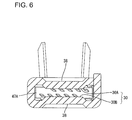
- FIG. 6 is a cross section view of the female terminal hardware taken along lines C-C in FIG. 2 .
- FIG. 7 is a perspective view of a terminal main body shown in FIG. 1 .
- FIG. 8 is a longitudinal section plan view of the terminal main body, illustrating the terminal main body in a state before a louver terminal is inserted into the terminal main body.
- FIG. 9 is a cross section view of the terminal main body shown in FIG. 8 , illustrating the terminal main body in the state before the louver terminal is inserted into the terminal main body.
- FIG. 10 is a cross section view similar to FIG. 9 , illustrating a state in which latch pieces of the louver terminal contact with extended portions of the terminal main body when the louver terminal is inserted into the terminal main body.
- FIG. 11 is a cross section view similar to FIG. 10 , illustrating the latch pieces in a deflected state when the louver terminal is inserted into the terminal main body.
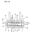
- FIG. 12 is a cross section view similar to FIG. 10 , illustrating the louver contained in the terminal main body completely.
- FIG. 13 is a perspective view of the louver terminal.
- FIG. 14 is a cross section view similar to FIG. 12 , illustrating a state in which a male terminal is coupled to the female terminal hardware.
- FIG. 15 is a cross section view similar to FIG. 14 , illustrating a state in which the male terminal is twisted in the female terminal hardware.
- a female terminal hardware in accordance with the invention is identified by the numeral 10 in FIGS. 1 to 15 .
- the female terminal hardware 10 is crimped on and secured to an end of a coated electrical cable.
- the coated electrical cable is arranged between devices (not shown) such as batteries, inverters and motors that constitute power sources for driving an electrical motor vehicle.
- a vertical direction designates upper and lower sides in FIG. 1
- a front end designates a left side
- a rear end designates a right side in FIG. 1 .
- the female terminal hardware 10 includes a terminal main body 20 and a louver terminal 40 .
- the louver terminal 40 is contained in the terminal main body 20 and is connected to a mating male terminal TA ( FIG. 14 ).
- the terminal main body 20 is made of copper or copper alloy and includes a box-like terminal connecting section 21 and an open barrel shape electrical cable connecting section 32 .
- the terminal connecting section 21 is an elongate rectangular tube with front and rear openings 24 and 39 .
- the front opening 24 defines a wide rectangular connecting aperture for receiving the mating male terminal TA.
- a communicating space 22 is defined in the terminal connecting section 21 and communicates with the openings 24 and 39 .
- a terminal containing section 23 is defined in an intermediate part of the communicating space 22 for housing a louver terminal 40 .
- the terminal connecting section 21 has opposite left and right side walls 21 B and 21 D.
- a long rectangular louver terminal inserting aperture 25 is formed in the left side wall 21 B and is configured for receiving the louver terminal 40 , as shown in FIG. 1 .
- the left side wall 21 B is cut off at an intermediate part.
- the right side wall 21 D of the terminal connecting section 21 has two positioning apertures 26 spaced apart in the front and rear directions, as shown in FIG. 4 .
- the positioning apertures 26 are formed by cutting off lower ends of the right side wall 21 D, as shown in FIG. 12 , so that areas outside of the terminal connecting section 21 communicate with the terminal containing section 23 .
- Upper and lower walls 21 A and 21 C extend between the side walls 21 B and 21 D, as shown in FIGS. 3 and 7 .
- Extensions 27 A and 27 B extend from the upper and lower walls 21 A and 21 C at the louver terminal inserting aperture 25 in the left side wall 21 B.
- the extensions 27 A and 27 B protrude to an outer surface of the left side wall 21 B.
- Slants 28 are provided on the front and rear ends of the extensions 27 A and 27 B and incline in toward the louver terminal inserting aperture 25 .
- the slants 28 are stepped with respect to the flat upper and lower walls 21 A and 21 C.
- steps 29 are provided on boundary areas between the slants 28 and inner surfaces of the upper and lower walls 21 A and 21 C.
- the steps 29 protrude in to the side of the louver terminal inserting aperture 25 .
- the steps 29 engage the louver terminal 40 to hold the louver terminal 40 in the terminal containing section 23 .
- Projections 30 A and 30 B are formed on portions of the upper and lower walls 21 A and 21 C near the front and rear ends of the terminal containing section 23 and project toward the communicating space 22 , as shown in FIG. 3 .
- the projections 30 A and 30 B define the front and rear boundaries of areas of the communicating space 22 that form the terminal containing section 23 . Heights of the projections 30 A and 30 B are substantially constant and their lengths extend on the inner surfaces of the upper and lower walls 21 A and 21 C in the entire width direction. The projections 30 A and 30 B restrain the louver terminal 40 from being moved front and rear in the connecting and disconnecting directions of the male terminal TA. The projections 30 A and 30 B guide the louver terminal 40 inserted into the terminal containing section 23 .
- Outer surfaces of the upper and lower walls 21 A and 21 C are provided with recesses 38 that receive the projections 30 A and 30 B.
- a rectangular aperture 31 is provided in the lower wall 21 C rearward of the projection 30 B ( FIG. 4 ).
- the electrical cable connecting section 32 includes a bottom plate 33 that extends back from the lower wall 21 C of the terminal connecting section 21 , as shown in FIG. 3 .
- An intermediate part of the bottom plate 33 in a width direction ( FIG. 7 ) is concave and an end of the coated electrical cable is disposed on the bottom plate 33 .
- Wire barrels 34 extend from opposite sides of the bottom plate 33 in the width direction and are crimped onto the core wire exposed from an end of the coated electrical cable to press-contact wire barrels 34 with the core wire.
- Serrations 35 extend in the width direction along the wire bottom plate 33 and continue to the wire barrels 34 .
- the serrations 35 strip an oxide film around the core wire upon crimping.
- the female terminal hardware 10 is formed by punching a metallic sheet into a developed pattern and bending the developed pattern.
- the projections 30 A and 30 B and slants 28 can be formed by punching and pressing.
- the louver terminal 40 is made of a material (for example, beryllium copper) having higher elasticity than the terminal main body 20 . As shown in FIG. 13 , the louver terminal 40 has two opposed contact plates 41 and 42 and a restraining section 51 that couples the contact plates 41 and 42 and restrains the louver terminal 40 from shifting to define an inserting space for receiving the male terminal TA.
- a material for example, beryllium copper
- the contact plates 41 and 42 include five contact pieces 43 juxtaposed in a width direction and contact piece holding sections 45 for coupling and holding ends of the contact pieces 43 to one another.
- Each contact piece 43 has a contact portion bent toward each of the horizontal contact piece holding sections 45 so that intermediate parts in the front and rear directions protrude inward. Opposite sides of each contact piece 43 define a contact portion 43 A extending out to the contact piece holding section 45 .
- the contact pieces 43 of the contact plates 41 and 42 as seen in an inserting direction of the male terminal TA, are inclined in substantially the same direction and define an inserting space narrower than a thickness of the male terminal TA between the upper and lower contact pieces 43 , as shown in FIG. 12 .
- each of the contact piece holding sections 45 defines a frame-like configuration that surrounds five contact pieces 43 .
- Each contact piece holding section 45 includes a contact piece coupling 46 for connecting adjacent contact pieces 43 to one another, and side couplings 47 for connecting the contact piece coupling portions 46 at sides of the contact pieces 43 .
- Each contact piece coupling 46 has contact pieces 48 that slant in an upper direction to contact with a wall surface of the terminal containing section 23 at every part for coupling the adjacent contact pieces 43 to one another.
- the side coupling 47 at the side of the restraining section 51 has two latches 49 that engage the steps 29 of the terminal connecting sections 21 to position the louver terminal 40 .
- the latches 49 are disposed on opposite sides of the restraining section 51 and slant outward.
- Positioning projections 50 protrude horizontally from the lower contact plate 42 at an end of the side coupling 47 opposite the restraining section 51 and hence at an inner part in the inserting direction of the louver terminal 40 .
- the positioning projections 50 are disposed in the positioning apertures 26 of the terminal connecting portion 21 to position the louver terminal 40 in the front and rear directions, which define the attaching and detaching directions of the male terminal TA.
- a deflection restraining piece 47 A stands vertically up from the side coupling 47 that has the positioning projection 50 on the end on the lower contact plate 42 , as shown in FIG. 9 .
- the deflection restraining piece 47 A and the restraining section 51 have substantially equal heights.
- An upper end of the deflection restraining piece 47 A is immediately below the inner part of the upper contact plate 41 in its inserting direction.
- the deflection restraining piece 47 A restrains the contact plates 41 and 42 from being deflected around the restraining section 51 in an inward direction.
- the restraining section 51 couples intermediate parts of the side couplings 47 of the upper and lower contact plates 41 and 42 at a side of the louver terminal inserting aperture 25 . That is, the restraining section 51 is at a side area of the juxtaposed contact pieces 43 (in an arranging direction of the contact pieces 43 ). A height of the restraining section 51 is set so that the contact pieces 48 of the upper and lower contact plates 41 and 42 contact with the upper and lower walls 21 A and 21 C. Thus, the louver terminal 40 is restrained from being shifted up and down and the inserting space for the male terminal AT is defined between the upper and lower contact plates 41 and 42 . A circular through-hole 51 A is formed in a central part of the restraining section 51 .
- the louver terminal 40 is inserted into the louver terminal inserting aperture 25 with the positioning projection piece 50 in the lead.
- the contact portions 43 A of the contact pieces 48 and 43 are juxtaposed in the inserting direction and move into the terminal containing section 23 while sliding on the inner surfaces of the upper and lower walls 21 A and 21 C, respectively.
- the projections 30 A and 30 B on the upper and lower walls 21 A and 21 C guide the contact pieces 48 at the front and rear sides, thereby restraining the louver terminal 40 from being shifted in the inserting direction.
- the latches 49 of the louver terminal 40 contact edges of the slants 28 on the upper and lower extensions 27 A and 27 B ( FIG. 10 ), and hence the latch pieces 49 deflect ( FIG. 11 ).
- the positioning projection pieces 50 at a distal end of the louver terminal 40 are inserted into the positioning apertures 26 in the terminal main body 21 , and the latches 49 at the rear side reach the steps 29 to return to the original state.
- the rear side part of the louver terminal 40 in the inserting direction engages the steps 29 to hold the louver terminal 40 in the terminal containing section 23 .
- the mating male terminal TA is inserted into the connecting aperture 24 ( FIG. 3 ) in the terminal main body 20 and passes through the space between the upper and lower projections 30 A and 30 B at the front of the terminal containing section 23 .
- the male terminal TA is disposed between and slides on the contact pieces 43 , and the leading end of the male terminal TA moves into a space between the rear projections 30 A and 30 B of the terminal containing section 23 .
- a clearance between the projections 30 A and 30 B on the upper and lower walls 21 A and 21 C and the male terminal TA is very small.
- the male terminal TA will not twist during insertion.
- the restraining section 51 is at the side of the contact pieces 43 .
- the distal end of the male terminal TA cannot contact the restraining section 51 as the male terminal TA is inserted into the terminal containing section 23 and slides on the contact pieces 43 . Accordingly, it is not necessary to elongate the louver terminal 40 according to a length of the male terminal TA to be received in the louver terminal 40 , and the female terminal hardware 10 can be down sized while maintaining good electrical connection.
- the louver terminal inserting aperture 25 is on the side area of the terminal connecting section 21 .
- the restraining section 51 is at the side area of the louver terminal inserting aperture 25 .
- the restraining section 51 can prevent foreign particles from entering the louver terminal inserting aperture 25 .
- the projections 30 A and 30 B extend along the inserting direction of the louver terminal 40 A on a portion of an inner surface of the terminal connecting section 21 on which the louver terminal 40 is not disposed.
- the projections 30 A and 30 B extend in a direction perpendicular to the inserting direction of the male terminal TA and prevent the male terminal TA from being twisted during insertion.
- the projections 30 A and 30 B also guide and position the louver terminal 40 .
- the louver terminal 40 has the contact pieces 43 and contact piece holding sections 45 for holding the contact pieces 43 .
- the restraining section 51 connects the opposed contact piece holding sections 45 .
- the contact pieces 43 contact the upper and lower sides of the male terminal TA and obtain a greater contact area between the male terminal TA and the contact pieces 43 in comparison with the case where the contact pieces 43 contact only one side of the male terminal TA.
- the restraining section 51 couples the contact piece holding sections 45 to each other, thereby simplifying a structure of the louver terminal 40 .
- the convex steps 29 are provided on the inner wall of the terminal connecting section 21 and the louver terminal 40 has latches 49 that engage the steps 29 .
- the louver terminal 40 is latched in the terminal connecting section 21 .
- the louver terminal 40 need not be inserted from the side into the louver terminal inserting aperture 25 on the side surface of the terminal main body 20 .
- the louver terminal 40 may be inserted into the terminal inserting aperture 25 from the front of the terminal main body 20 .
- the louver terminal 40 may be inserted into the terminal main body 20 from the connecting aperture 24 provided on the front end of the terminal main body 20 to insert the male terminal TA. Since the restraining section 51 is disposed on the side area of the contact pieces 43 in this structure, the male terminal TA does not contact with the restraining section 51 upon inserting the male terminal TA. Accordingly, it is possible to downsize the female terminal hardware.
- the louver terminal 40 includes two contact plates 41 and 42 in the above embodiment, this is not limited.
- the louver terminal 40 may include a single contact plate, which is provided with a restraining section that restrains the louver terminal from being shifted to obtain an inserting space for the male terminal TA.
Applications Claiming Priority (2)
| Application Number | Priority Date | Filing Date | Title |
|---|---|---|---|
| JP2009190216A JP5381492B2 (ja) | 2009-08-19 | 2009-08-19 | 雌端子金具 |
| JP2009-190216 | 2009-08-19 |
Publications (2)
| Publication Number | Publication Date |
|---|---|
| US20110045712A1 US20110045712A1 (en) | 2011-02-24 |
| US8038488B2 true US8038488B2 (en) | 2011-10-18 |
Family
ID=43605727
Family Applications (1)
| Application Number | Title | Priority Date | Filing Date |
|---|---|---|---|
| US12/849,844 Expired - Fee Related US8038488B2 (en) | 2009-08-19 | 2010-08-04 | Female terminal hardware |
Country Status (2)
| Country | Link |
|---|---|
| US (1) | US8038488B2 (ja) |
| JP (1) | JP5381492B2 (ja) |
Cited By (13)
| Publication number | Priority date | Publication date | Assignee | Title |
|---|---|---|---|---|
| US20110244714A1 (en) * | 2008-12-12 | 2011-10-06 | Tyco Electronics Amp Gmbh | High-current plug-in connector |
| US8128441B2 (en) * | 2010-04-08 | 2012-03-06 | Sumitomo Wiring Systems, Ltd. | Terminal fitting connecting structure |
| US20120108113A1 (en) * | 2009-07-03 | 2012-05-03 | Yazaki Corporation | Terminal |
| US20120289101A1 (en) * | 2009-11-11 | 2012-11-15 | Chul-Sub Lee | Connector Terminal |
| US20120315802A1 (en) * | 2010-03-16 | 2012-12-13 | Rosenberger Hochfrequenztechnik Gmbh & Co. Kg | High current connector |
| US20140038472A1 (en) * | 2012-07-31 | 2014-02-06 | Rockwell Automation Technologies, Inc. | Power circuit electrical connection system and method |
| US20140099843A1 (en) * | 2011-06-07 | 2014-04-10 | Japan Aviation Electronics Industry, Limited | Contact element and connector |
| US20150222040A1 (en) * | 2014-02-06 | 2015-08-06 | Dai-Ichi Seiko Co., Ltd. | Connector terminal |
| US20160181706A1 (en) * | 2014-12-17 | 2016-06-23 | Toyota Jidosha Kabushiki Kaisha | Connector |
| US10256560B2 (en) * | 2016-10-28 | 2019-04-09 | Te Connectivity Germany Gmbh | Flat contact socket with a cantilever |
| US20190190183A1 (en) * | 2017-12-20 | 2019-06-20 | Yazaki Corporation | Connection terminal and connector |
| US10608362B2 (en) * | 2018-04-03 | 2020-03-31 | Yazaki Corporation | Relay terminal and relay connector |
| US20220209450A1 (en) * | 2020-12-28 | 2022-06-30 | Hyundai Motor Company | Electrical Connection Device For Vehicle |
Families Citing this family (22)
| Publication number | Priority date | Publication date | Assignee | Title |
|---|---|---|---|---|
| JP5971899B2 (ja) * | 2011-05-12 | 2016-08-17 | 日本航空電子工業株式会社 | コンタクトエレメント及びコネクタ |
| JP5858565B2 (ja) * | 2011-06-07 | 2016-02-10 | 日本航空電子工業株式会社 | コンタクトエレメント及びコネクタ |
| JP5723694B2 (ja) | 2011-06-21 | 2015-05-27 | 矢崎総業株式会社 | 雌端子 |
| JP5723695B2 (ja) | 2011-06-21 | 2015-05-27 | 矢崎総業株式会社 | 雌端子 |
| JP5763984B2 (ja) | 2011-06-21 | 2015-08-12 | 矢崎総業株式会社 | 端子接点構造及びこの端子接点構造を備えた端子 |
| JP5732327B2 (ja) * | 2011-06-23 | 2015-06-10 | 日本航空電子工業株式会社 | 電気コンタクト、及び、電気コネクタ |
| JP5732330B2 (ja) * | 2011-06-27 | 2015-06-10 | 日本航空電子工業株式会社 | 電気コンタクト、及び、電気コネクタ |
| KR101839618B1 (ko) * | 2011-09-07 | 2018-03-19 | 엘에스이브이코리아 주식회사 | 파워 커넥터 및 파워 커넥팅 시스템 |
| JP5815352B2 (ja) | 2011-09-27 | 2015-11-17 | 矢崎総業株式会社 | 雌端子 |
| JP6055173B2 (ja) | 2011-09-27 | 2016-12-27 | 矢崎総業株式会社 | 雌端子 |
| DE102012017949A1 (de) * | 2011-09-28 | 2013-03-28 | Sumitomo Wiring Systems, Ltd. | Anschlusspassstück |
| JP5639100B2 (ja) * | 2012-03-12 | 2014-12-10 | 古河電気工業株式会社 | コネクタ端子用接触ばね及び雌端子、雄端子、コネクタ |
| DE102012219741A1 (de) * | 2012-10-29 | 2014-04-30 | Tyco Electronics Amp Gmbh | Elektrischer Kontakt und Steckverbinder mit einem solchen elektrischen Kontakt |
| JP2015076199A (ja) * | 2013-10-07 | 2015-04-20 | 矢崎総業株式会社 | 雌端子金具 |
| EP3051635B1 (en) * | 2015-01-30 | 2018-01-17 | TE Connectivity Germany GmbH | Electric contact means and electrical cable assembly for the automotive industry |
| DE102015216632A1 (de) * | 2015-08-31 | 2017-03-02 | Te Connectivity Germany Gmbh | Anordnung zum Herstellen einer elektrischen Verbindung zwischen einem Flachkontakt und einem Hochstromleiter |
| BE1023715B1 (nl) * | 2016-06-07 | 2017-06-26 | Daviation Bvba | Elektrische voedingsstekker en elektrische contrastekker |
| DE102017001166A1 (de) | 2017-01-31 | 2018-08-02 | Kostal Kontakt Systeme Gmbh | Kontaktlamelle für ein buchsenartiges Steckverbinderteil und buchsenartiges Steckverbinderteil |
| JP6860836B2 (ja) * | 2018-02-27 | 2021-04-21 | 株式会社オートネットワーク技術研究所 | コネクタ |
| US20190273351A1 (en) * | 2018-03-02 | 2019-09-05 | Mersen Usa Newburyport-Ma, Llc | Electrical connector |
| US10992073B1 (en) * | 2019-12-20 | 2021-04-27 | Lear Corporation | Electrical terminal assembly with increased contact area |
| CN117913571A (zh) * | 2020-12-30 | 2024-04-19 | 泰科电子(上海)有限公司 | 端子组件和连接器 |
Citations (3)
| Publication number | Priority date | Publication date | Assignee | Title |
|---|---|---|---|---|
| US4934965A (en) * | 1988-05-26 | 1990-06-19 | Kabelwerke Reinshagen Gmbh | Electrical connector with a spring cage receptacle |
| US7150660B2 (en) | 2001-09-21 | 2006-12-19 | Tyco Electronics Corporation | High current automotive electrical connector and terminal |
| US7789720B2 (en) * | 2007-04-03 | 2010-09-07 | Lear Corporation | Electrical terminal assembly and method of using the electrical terminal assembly |
Family Cites Families (3)
| Publication number | Priority date | Publication date | Assignee | Title |
|---|---|---|---|---|
| JP4431259B2 (ja) * | 2000-08-28 | 2010-03-10 | 三菱電線工業株式会社 | 接続端子 |
| JP4443017B2 (ja) * | 2000-09-25 | 2010-03-31 | 三菱電線工業株式会社 | 接続端子 |
| DE102004015345A1 (de) * | 2004-03-30 | 2005-10-27 | Kostal Kontakt Systeme Gmbh | Elektrischer Steckhülsenkontakt für Hochstromanwendungen |
-
2009
- 2009-08-19 JP JP2009190216A patent/JP5381492B2/ja not_active Expired - Fee Related
-
2010
- 2010-08-04 US US12/849,844 patent/US8038488B2/en not_active Expired - Fee Related
Patent Citations (3)
| Publication number | Priority date | Publication date | Assignee | Title |
|---|---|---|---|---|
| US4934965A (en) * | 1988-05-26 | 1990-06-19 | Kabelwerke Reinshagen Gmbh | Electrical connector with a spring cage receptacle |
| US7150660B2 (en) | 2001-09-21 | 2006-12-19 | Tyco Electronics Corporation | High current automotive electrical connector and terminal |
| US7789720B2 (en) * | 2007-04-03 | 2010-09-07 | Lear Corporation | Electrical terminal assembly and method of using the electrical terminal assembly |
Cited By (24)
| Publication number | Priority date | Publication date | Assignee | Title |
|---|---|---|---|---|
| US8337240B2 (en) * | 2008-12-12 | 2012-12-25 | Tyco Electronics Amp Gmbh | High-current plug-in connector |
| US20110244714A1 (en) * | 2008-12-12 | 2011-10-06 | Tyco Electronics Amp Gmbh | High-current plug-in connector |
| US20120108113A1 (en) * | 2009-07-03 | 2012-05-03 | Yazaki Corporation | Terminal |
| US8668531B2 (en) * | 2009-07-03 | 2014-03-11 | Yazaki Corporation | Terminal |
| US8827754B2 (en) * | 2009-11-11 | 2014-09-09 | Tyco Electronics Amp Korea, Ltd. | Connector terminal |
| US20120289101A1 (en) * | 2009-11-11 | 2012-11-15 | Chul-Sub Lee | Connector Terminal |
| US20120315802A1 (en) * | 2010-03-16 | 2012-12-13 | Rosenberger Hochfrequenztechnik Gmbh & Co. Kg | High current connector |
| US8827755B2 (en) * | 2010-03-16 | 2014-09-09 | Rosenberger Hochfrequenztechnik GmbH & Co, KG | High current connector |
| US8128441B2 (en) * | 2010-04-08 | 2012-03-06 | Sumitomo Wiring Systems, Ltd. | Terminal fitting connecting structure |
| US9257769B2 (en) * | 2011-06-07 | 2016-02-09 | Japan Aviation Electronics Industry, Limited | Contact element and connector |
| US20140099843A1 (en) * | 2011-06-07 | 2014-04-10 | Japan Aviation Electronics Industry, Limited | Contact element and connector |
| US20140287633A1 (en) * | 2012-07-31 | 2014-09-25 | Rockwell Automation Technologies, Inc. | Power circuit electrical connection system |
| US8764495B2 (en) * | 2012-07-31 | 2014-07-01 | Rockwell Automation Technologies, Inc. | Power circuit electrical connection system and method |
| US9225093B2 (en) * | 2012-07-31 | 2015-12-29 | Rockwell Automation Technologies, Inc. | Power circuit electrical connection system |
| US20140038472A1 (en) * | 2012-07-31 | 2014-02-06 | Rockwell Automation Technologies, Inc. | Power circuit electrical connection system and method |
| US20150222040A1 (en) * | 2014-02-06 | 2015-08-06 | Dai-Ichi Seiko Co., Ltd. | Connector terminal |
| US9190758B2 (en) * | 2014-02-06 | 2015-11-17 | Dai-Ichi Seiko Co., Ltd. | Connector terminal |
| US20160181706A1 (en) * | 2014-12-17 | 2016-06-23 | Toyota Jidosha Kabushiki Kaisha | Connector |
| US9673549B2 (en) * | 2014-12-17 | 2017-06-06 | Toyota Jidosha Kabushiki Kaisha | Connector with movement suppression function during excessive vibration |
| US10256560B2 (en) * | 2016-10-28 | 2019-04-09 | Te Connectivity Germany Gmbh | Flat contact socket with a cantilever |
| US20190190183A1 (en) * | 2017-12-20 | 2019-06-20 | Yazaki Corporation | Connection terminal and connector |
| US10608362B2 (en) * | 2018-04-03 | 2020-03-31 | Yazaki Corporation | Relay terminal and relay connector |
| US20220209450A1 (en) * | 2020-12-28 | 2022-06-30 | Hyundai Motor Company | Electrical Connection Device For Vehicle |
| US11749926B2 (en) * | 2020-12-28 | 2023-09-05 | Hyundai Motor Company | Electrical connection device for vehicle |
Also Published As
| Publication number | Publication date |
|---|---|
| JP2011044256A (ja) | 2011-03-03 |
| JP5381492B2 (ja) | 2014-01-08 |
| US20110045712A1 (en) | 2011-02-24 |
Similar Documents
| Publication | Publication Date | Title |
|---|---|---|
| US8038488B2 (en) | Female terminal hardware | |
| US6524143B2 (en) | Female crimp terminal | |
| US8128441B2 (en) | Terminal fitting connecting structure | |
| US7938694B2 (en) | Connector terminal and connector with the connector terminal | |
| US7458863B2 (en) | Terminal fitting and a connector | |
| US9401550B2 (en) | Connector | |
| US20050191912A1 (en) | Female terminal fitting and a blank for a plurality of terminal fittings | |
| US8348707B2 (en) | Terminal fitting | |
| US20070099520A1 (en) | Connecting terminal | |
| US7553203B2 (en) | Connecting terminal | |
| EP2375512B1 (en) | Terminal fitting and production method therefor | |
| US20090142958A1 (en) | Connector | |
| US6997761B2 (en) | Electrical contact element | |
| US11177601B2 (en) | Terminal having a conductor and a spring | |
| US11245213B2 (en) | Clean body electric terminal | |
| US6629864B2 (en) | Electrical contact for plug-in connector | |
| US10756478B2 (en) | Terminal and method of connecting electric wire to terminal | |
| CN110870143B (zh) | 端子零件 | |
| US11349242B2 (en) | Male wire terminal and male wire connector | |
| US10826229B2 (en) | Connector with coupling portion | |
| US11381009B2 (en) | Contact and connector | |
| US10804625B2 (en) | Terminal, method of connecting electric wire to terminal, and jig | |
| CN117795786A (zh) | 连接器 | |
| EP1548883A1 (en) | Electric connection box and bus bar-mounting structure thereof | |
| JP2021057208A (ja) | 雄端子、および雄コネクタ |
Legal Events
| Date | Code | Title | Description |
|---|---|---|---|
| AS | Assignment |
Owner name: SUMITOMO WIRING SYSTEMS, LTD., JAPAN Free format text: ASSIGNMENT OF ASSIGNORS INTEREST;ASSIGNOR:MUKUNO, JUNICHI;REEL/FRAME:024784/0411 Effective date: 20100720 |
|
| STCF | Information on status: patent grant |
Free format text: PATENTED CASE |
|
| FPAY | Fee payment |
Year of fee payment: 4 |
|
| FEPP | Fee payment procedure |
Free format text: MAINTENANCE FEE REMINDER MAILED (ORIGINAL EVENT CODE: REM.); ENTITY STATUS OF PATENT OWNER: LARGE ENTITY |
|
| LAPS | Lapse for failure to pay maintenance fees |
Free format text: PATENT EXPIRED FOR FAILURE TO PAY MAINTENANCE FEES (ORIGINAL EVENT CODE: EXP.); ENTITY STATUS OF PATENT OWNER: LARGE ENTITY |
|
| STCH | Information on status: patent discontinuation |
Free format text: PATENT EXPIRED DUE TO NONPAYMENT OF MAINTENANCE FEES UNDER 37 CFR 1.362 |
|
| FP | Lapsed due to failure to pay maintenance fee |
Effective date: 20191018 |