US7821663B2 - Image supply device, control method of the device, and printing system - Google Patents
Image supply device, control method of the device, and printing system Download PDFInfo
- Publication number
- US7821663B2 US7821663B2 US11/736,340 US73634007A US7821663B2 US 7821663 B2 US7821663 B2 US 7821663B2 US 73634007 A US73634007 A US 73634007A US 7821663 B2 US7821663 B2 US 7821663B2
- Authority
- US
- United States
- Prior art keywords
- image
- reference information
- printing device
- printer
- Prior art date
- Legal status (The legal status is an assumption and is not a legal conclusion. Google has not performed a legal analysis and makes no representation as to the accuracy of the status listed.)
- Expired - Fee Related, expires
Links
Images


Classifications
-
- G—PHYSICS
- G06—COMPUTING OR CALCULATING; COUNTING
- G06F—ELECTRIC DIGITAL DATA PROCESSING
- G06F3/00—Input arrangements for transferring data to be processed into a form capable of being handled by the computer; Output arrangements for transferring data from processing unit to output unit, e.g. interface arrangements
- G06F3/12—Digital output to print unit, e.g. line printer, chain printer
- G06F3/1201—Dedicated interfaces to print systems
- G06F3/1202—Dedicated interfaces to print systems specifically adapted to achieve a particular effect
- G06F3/1203—Improving or facilitating administration, e.g. print management
- G06F3/1205—Improving or facilitating administration, e.g. print management resulting in increased flexibility in print job configuration, e.g. job settings, print requirements, job tickets
-
- B—PERFORMING OPERATIONS; TRANSPORTING
- B41—PRINTING; LINING MACHINES; TYPEWRITERS; STAMPS
- B41J—TYPEWRITERS; SELECTIVE PRINTING MECHANISMS, i.e. MECHANISMS PRINTING OTHERWISE THAN FROM A FORME; CORRECTION OF TYPOGRAPHICAL ERRORS
- B41J21/00—Column, tabular or like printing arrangements; Means for centralising short lines
-
- B—PERFORMING OPERATIONS; TRANSPORTING
- B41—PRINTING; LINING MACHINES; TYPEWRITERS; STAMPS
- B41J—TYPEWRITERS; SELECTIVE PRINTING MECHANISMS, i.e. MECHANISMS PRINTING OTHERWISE THAN FROM A FORME; CORRECTION OF TYPOGRAPHICAL ERRORS
- B41J29/00—Details of, or accessories for, typewriters or selective printing mechanisms not otherwise provided for
- B41J29/38—Drives, motors, controls or automatic cut-off devices for the entire printing mechanism
-
- G—PHYSICS
- G06—COMPUTING OR CALCULATING; COUNTING
- G06F—ELECTRIC DIGITAL DATA PROCESSING
- G06F3/00—Input arrangements for transferring data to be processed into a form capable of being handled by the computer; Output arrangements for transferring data from processing unit to output unit, e.g. interface arrangements
- G06F3/12—Digital output to print unit, e.g. line printer, chain printer
- G06F3/1201—Dedicated interfaces to print systems
- G06F3/1202—Dedicated interfaces to print systems specifically adapted to achieve a particular effect
- G06F3/1203—Improving or facilitating administration, e.g. print management
- G06F3/1208—Improving or facilitating administration, e.g. print management resulting in improved quality of the output result, e.g. print layout, colours, workflows, print preview
-
- G—PHYSICS
- G06—COMPUTING OR CALCULATING; COUNTING
- G06F—ELECTRIC DIGITAL DATA PROCESSING
- G06F3/00—Input arrangements for transferring data to be processed into a form capable of being handled by the computer; Output arrangements for transferring data from processing unit to output unit, e.g. interface arrangements
- G06F3/12—Digital output to print unit, e.g. line printer, chain printer
- G06F3/1201—Dedicated interfaces to print systems
- G06F3/1202—Dedicated interfaces to print systems specifically adapted to achieve a particular effect
- G06F3/1218—Reducing or saving of used resources, e.g. avoiding waste of consumables or improving usage of hardware resources
- G06F3/122—Reducing or saving of used resources, e.g. avoiding waste of consumables or improving usage of hardware resources with regard to computing resources, e.g. memory, CPU
-
- G—PHYSICS
- G06—COMPUTING OR CALCULATING; COUNTING
- G06F—ELECTRIC DIGITAL DATA PROCESSING
- G06F3/00—Input arrangements for transferring data to be processed into a form capable of being handled by the computer; Output arrangements for transferring data from processing unit to output unit, e.g. interface arrangements
- G06F3/12—Digital output to print unit, e.g. line printer, chain printer
- G06F3/1201—Dedicated interfaces to print systems
- G06F3/1223—Dedicated interfaces to print systems specifically adapted to use a particular technique
- G06F3/1237—Print job management
- G06F3/1244—Job translation or job parsing, e.g. page banding
- G06F3/1245—Job translation or job parsing, e.g. page banding by conversion to intermediate or common format
-
- G—PHYSICS
- G06—COMPUTING OR CALCULATING; COUNTING
- G06F—ELECTRIC DIGITAL DATA PROCESSING
- G06F3/00—Input arrangements for transferring data to be processed into a form capable of being handled by the computer; Output arrangements for transferring data from processing unit to output unit, e.g. interface arrangements
- G06F3/12—Digital output to print unit, e.g. line printer, chain printer
- G06F3/1201—Dedicated interfaces to print systems
- G06F3/1278—Dedicated interfaces to print systems specifically adapted to adopt a particular infrastructure
- G06F3/128—Direct printing, e.g. sending document file, using memory stick, printing from a camera
-
- H—ELECTRICITY
- H04—ELECTRIC COMMUNICATION TECHNIQUE
- H04N—PICTORIAL COMMUNICATION, e.g. TELEVISION
- H04N1/00—Scanning, transmission or reproduction of documents or the like, e.g. facsimile transmission; Details thereof
- H04N1/00127—Connection or combination of a still picture apparatus with another apparatus, e.g. for storage, processing or transmission of still picture signals or of information associated with a still picture
- H04N1/00278—Connection or combination of a still picture apparatus with another apparatus, e.g. for storage, processing or transmission of still picture signals or of information associated with a still picture with a printing apparatus, e.g. a laser beam printer
-
- H—ELECTRICITY
- H04—ELECTRIC COMMUNICATION TECHNIQUE
- H04N—PICTORIAL COMMUNICATION, e.g. TELEVISION
- H04N1/00—Scanning, transmission or reproduction of documents or the like, e.g. facsimile transmission; Details thereof
- H04N1/387—Composing, repositioning or otherwise geometrically modifying originals
- H04N1/3872—Repositioning or masking
- H04N1/3873—Repositioning or masking defined only by a limited number of coordinate points or parameters, e.g. corners, centre; for trimming
- H04N1/3875—Repositioning or masking defined only by a limited number of coordinate points or parameters, e.g. corners, centre; for trimming combined with enlarging or reducing
-
- H—ELECTRICITY
- H04—ELECTRIC COMMUNICATION TECHNIQUE
- H04N—PICTORIAL COMMUNICATION, e.g. TELEVISION
- H04N1/00—Scanning, transmission or reproduction of documents or the like, e.g. facsimile transmission; Details thereof
- H04N1/40—Picture signal circuits
-
- H—ELECTRICITY
- H04—ELECTRIC COMMUNICATION TECHNIQUE
- H04N—PICTORIAL COMMUNICATION, e.g. TELEVISION
- H04N23/00—Cameras or camera modules comprising electronic image sensors; Control thereof
-
- H—ELECTRICITY
- H04—ELECTRIC COMMUNICATION TECHNIQUE
- H04N—PICTORIAL COMMUNICATION, e.g. TELEVISION
- H04N2201/00—Indexing scheme relating to scanning, transmission or reproduction of documents or the like, and to details thereof
- H04N2201/0008—Connection or combination of a still picture apparatus with another apparatus
- H04N2201/0015—Control of image communication with the connected apparatus, e.g. signalling capability
-
- H—ELECTRICITY
- H04—ELECTRIC COMMUNICATION TECHNIQUE
- H04N—PICTORIAL COMMUNICATION, e.g. TELEVISION
- H04N2201/00—Indexing scheme relating to scanning, transmission or reproduction of documents or the like, and to details thereof
- H04N2201/0077—Types of the still picture apparatus
- H04N2201/0084—Digital still camera
-
- H—ELECTRICITY
- H04—ELECTRIC COMMUNICATION TECHNIQUE
- H04N—PICTORIAL COMMUNICATION, e.g. TELEVISION
- H04N2201/00—Indexing scheme relating to scanning, transmission or reproduction of documents or the like, and to details thereof
- H04N2201/32—Circuits or arrangements for control or supervision between transmitter and receiver or between image input and image output device, e.g. between a still-image camera and its memory or between a still-image camera and a printer device
- H04N2201/3201—Display, printing, storage or transmission of additional information, e.g. ID code, date and time or title
- H04N2201/3225—Display, printing, storage or transmission of additional information, e.g. ID code, date and time or title of data relating to an image, a page or a document
- H04N2201/3242—Display, printing, storage or transmission of additional information, e.g. ID code, date and time or title of data relating to an image, a page or a document of processing required or performed, e.g. for reproduction or before recording
-
- H—ELECTRICITY
- H04—ELECTRIC COMMUNICATION TECHNIQUE
- H04N—PICTORIAL COMMUNICATION, e.g. TELEVISION
- H04N2201/00—Indexing scheme relating to scanning, transmission or reproduction of documents or the like, and to details thereof
- H04N2201/32—Circuits or arrangements for control or supervision between transmitter and receiver or between image input and image output device, e.g. between a still-image camera and its memory or between a still-image camera and a printer device
- H04N2201/3201—Display, printing, storage or transmission of additional information, e.g. ID code, date and time or title
- H04N2201/3278—Transmission
Definitions
- the present invention relates to a printing system which has an image supply device and a printing device and causes the printing device to print an image based on image data supplied from the image supply device, the image supply device, and a control method of the device.
- a so-called digital camera direct printing system is becoming popular, which directly connects a printer to a digital still camera (to be referred to as a DSC hereinafter) via an interface such as a USB and transmits a photo image stored in a storage medium (memory card) in the DSC to the printer to make it print the image.
- a DSC digital still camera
- the DSC transmits the JPEG file of a print target image to the printer.
- the printer converts the JPEG file into a printable data format by, for example, decompression, color conversion, and resize and prints the image.
- a high-resolution DSC capable of capturing and storing image data with 8,000,000 pixels or more is also commercially available.
- Patent reference 1 proposes a digital camera direct printing system capable of printing an image based on image data from a DSC and a print format including the paper size in a printer by using a unique print protocol that is not so general.
- a DSC converts a JPEG file into a printable data format by, for example, decompression, color conversion, and resizes and transmits it to a printer, thereby reducing the image process load on the printer.
- a DSC corrects variations in color reproduction characteristic between printers, converts image data into a general image file such as JPEG, and transmits it to a printer. This allows for obtaining a stable image independently of the print characteristics of a printer.
- Patent reference 1 Japanese Patent Laid-Open No. 8-32911
- Patent reference 2 Japanese Patent Laid-Open No. 10-290470
- Patent reference 3 Japanese Patent Laid-Open No. 2003-134457
- the system does not always guarantee that the DSC will transmit image data suitable for the printer.
- image data required by the printer is not always appropriately set when based only on Capability sent from the printer. This is because image data actually suitable for the printer may depend on the paper size and layout selected by the user on the UI of the DSC. More specifically, the suitable orientation and size of image data change between a mode wherein one photo is laid out and printed in one page and a mode wherein two photos are laid out and printed in one page.
- a print format allowable by the printer is sent to the DSC.
- the DSC changes the print specifications based on the format.
- image data is converted at the discretion of the DSC, and its image quality is not always preferable for the printing device.
- the DSC may excessively reduce the image data and make the quality so poor that the printer cannot execute a high quality process.
- the printer notifies the DSC of “A4” as the printable paper size. If the printer has no paper size detection function, the user selects the size of paper sheets set in the printer by using its setting panel and notifies the DSC of the result. In either case, printer specifications which are known to the printer at that point in time are transmitted from the printer to the DSC. There is no guarantee that image data sent from the DSC is suitable for the printer. This is because even in this case, image data suitable for the printer may depend on the paper size and layout selected by the user on the UI of the DSC.
- Patent references 2 and 3 describe the print characteristics of a printer as being acquired from the printer. Image data to be transmitted to the printer is converted based only on the acquired print characteristics. Even when the DSC should have converted an image in accordance with the printer, the printer must execute printing using only the converted image. There is no way to allow the printer to adaptively acquire desired image data from the DSC based on print conditions or its own capability.
- the prior arts include no description about an image process or print process according to the desire of a DSC user who wants high-quality image printing.
- An image supply device has the following arrangement. That is, there is provided an image supply device for supplying image data to a printing device, characterized by comprising:
- setting means for setting a first reference number and a second reference number to, of images to be supplied to the printing device, images that require a predetermined image process and remaining images, respectively;
- job issuance means for issuing a print job including a reference number of a print target image in accordance with a print instruction using the printing device;
- first image supply means for supplying, to the printing device, image data which corresponds to the first reference number and has undergone the predetermined image process, in a case that the reference number of an image requested by the printing device in response to the print job issued by said job issuance means is the first reference number;
- second image supply means for supplying, to the printing device, image data which corresponds to the second reference number and is read out, in a case that the reference number of an image requested by the printing device in response to the print job issued by said job issuance means is the second reference number.
- a printing system has the following arrangement. That is, there is provided a printing system in which an image supply device supplies image data to a printing device to print, characterized in that
- the image supply device comprises:
- setting means for setting a first reference number and a second reference number to, of images to be supplied to the printing device, images that require a predetermined image process and remaining images, respectively;
- job issuance means for issuing a print job including a reference number of a print target image in accordance with a print instruction using the printing device;
- first image supply means for supplying, to the printing device, image data which corresponds to the first reference number and has undergone the predetermined image process, in a case that the reference number of an image requested by the printing device in response to the print job issued by said job issuance means is the first reference number;
- second image supply means for supplying, to the printing device, image data which corresponds to the second reference number and is read out, in a case that the reference number of an image requested by the printing device in response to the print job issued by said job issuance means is the second reference number
- the printing device comprises:
- image request means for requesting image data of the image supply device by using the reference number of the image included in the print job
- the printing device receives and prints image data transmitted from the image supply device in response to a request by said image request means.
- a control method of an image supply device has the following arrangement. That is, there is provided a control method of an image supply device for supplying image data to a printing device, characterized by comprising:
- a reference number of an actual image and that of an image obtained by executing a predetermined image process for the actual image are set.
- the printing device designates an image by using a reference number.
- image data obtained by executing the predetermined image process on the image supply device can be supplied to the printing device.
- the printing device can adaptively acquire a suitable image in accordance with the contents of print settings and the state of the printing device itself.
- FIG. 1 depicts a schematic perspective view showing a PD printer according to an embodiment of the present invention
- FIG. 2 depicts a schematic view showing the operation panel of the PD printer according to the embodiment
- FIG. 3 is a block diagram showing the arrangement of the main part related to control of the PD printer according to the embodiment
- FIG. 4 is a block diagram showing the arrangement of a DSC according to the embodiment.
- FIG. 5 is a sequence chart for explaining a rough signal flow, in a case that a DSC issues a print request to a PD printer to execute printing in a printing system according to the embodiment;
- FIGS. 6A and 6B are flowcharts for explaining a process of executing communication between a digital camera (DSC) and a PD printer according to the first embodiment of the present invention to supply image data from the DSC to the printer and execute printing;
- DSC digital camera
- FIG. 7 depicts a view showing an example of a “schema” as an example of Capability information transmitted from the PD printer to the DSC in step S 22 in FIG. 6B ;
- FIG. 8 is a flowchart for explaining an image file creation process (step S 10 ) by the DSC according to the embodiment
- FIG. 9 is a flowchart for explaining an image data process (step S 28 ) by the PD printer according to the embodiment.
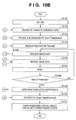
- FIGS. 10A and 10B are flowcharts for explaining the processes of the DSC and PD printer in a printing system according to the first embodiment of the present invention
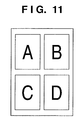
- FIG. 11 depicts a view for explaining an example of print layout according to the first embodiment of the present invention.
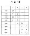
- FIG. 12 depicts a view for explaining the order of image rotation and resized image file generation and erase according to the first embodiment
- FIGS. 13A and 13B are flowcharts for explaining the processes of a DSC and a PD printer in a printing system according to the second embodiment of the present invention.
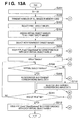
- FIGS. 14A and 14B are flowcharts for explaining the processes of the DSC and PD printer in the printing system according to the third embodiment of the present invention.
- FIG. 1 depicts a schematic perspective view showing a photo-direct printer device (to be referred to as a PD printer hereinafter) 1000 according to an embodiment of the present invention.
- the PD printer 1000 has a normal PC printer function of receiving data from a host computer (PC) and printing it, a function of directly reading and printing image data stored in a storage medium such as a memory card, and a function of receiving image data from a digital camera or PDA and printing it.
- PC host computer
- PDA digital camera
- the main body that forms the casing of the PD printer 1000 has casing members: a lower case 1001 , upper case 1002 , access cover 1003 , and discharge tray 1004 .
- the lower case 1001 forms almost the lower half of the PD printer 1000
- the upper case 1002 forms almost the upper half of the main body.
- These cases combine and form a hollow structure with a storage space to store mechanisms (to be described later).
- the upper and front surfaces have openings.
- the lower case 1001 rotatably holds the discharge tray 1004 at one end. As the discharge tray 1004 rotates, the opening in the front surface of the lower case 1001 opens/closes.
- the discharge tray 1004 Upon printing, the discharge tray 1004 rotates to the front side and opens to discharge printed sheets (including normal paper, dedicated paper, and resin sheets, all of which will simply be referred to as sheets hereinafter) from the opening and sequentially stack the discharged sheets.
- the discharge tray 1004 houses two auxiliary trays 1004 a and 1004 b .
- the sheet support area can be increased/reduced in three steps by pulling out the trays to the front side, as needed.
- the upper case 1002 holds the access cover 1003 at one end so as to open/close the opening formed in the upper surface. Opening the access cover 1003 enables exchanging a printhead cartridge (not shown), ink tank (not shown), or the like stored in the main body.
- a projection (not shown) formed on the back surface of the access cover 1003 rotates a cover opening/closing lever when the access cover 1003 opens/closes. The lever rotation position is detected by, for example, a microswitch to detect the open/closed state of the access cover 1003 .
- the upper case 1002 has a power key 1005 on its upper surface.
- the upper case 1002 has, on its right side, an operation panel 1010 with a liquid crystal display unit 1006 and various kinds of key switches.
- the structure of the operation panel 1010 will be described later in detail with reference to FIG. 2 .
- An automatic feeder 1007 automatically feeds sheets into the device main body.
- a paper interval selection lever 1008 adjusts the interval between the printhead and sheets.
- a card slot 1009 receives an adapter capable of mounting a memory card.
- the printer can directly receive, via the adapter, image data stored in the memory card and print it. Examples of the memory card (PC) are a compact Flash® memory, smart media, and memory stick.
- a viewer (liquid crystal display unit) 1011 is detachable from the main body of the PD printer 1000 .
- the viewer 1011 displays every frame image or index images when the user wants to search for a print target from images stored in the PC card.
- a USB terminal 1012 connects a digital camera (to be described later).
- the PD device 1000 has, on its back surface, a USB connector 1013 ( FIG. 3 ) to connect a personal computer (PC).
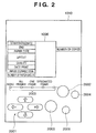
- FIG. 2 depicts a schematic view showing the operation panel 1010 of the PD printer 1000 according to the embodiment.
- the liquid crystal display unit 1006 displays menu items to set various data about items printed on its right and left sides. Examples of the displayed items are the number of the first photo image to be printed in a plurality of photo image files, the designated frame number (start frame designation/print frame designation), the number of the last photo image to be printed (end), the number of prints (number of copies), the type of sheets used for print (paper type), a setting of the number of photos to be printed on one sheet (layout), designation of print quality (quality), designation of ON/OFF of image capturing date print (date print), designation of ON/OFF of photo correction print (image correction), and a display of the number of paper sheets necessary for print (number of paper sheets).
- the user selects or designates these items by using cursor keys 2001 .
- the user can switch the type of print (e.g., index print, all frame print, one frame print, and designated frame print) by pressing a mode key 2002 .
- One of LEDs 2003 lights up in correspondence with the selected mode.
- a maintenance key 2004 is used for printer maintenance to, for example, clean the printhead.
- the user presses a print start key 2005 to give the instruction for the start of print or establish maintenance settings.
- the user presses a print stop key 2006 to stop print or give the instruction to stop maintenance operation.
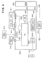
- FIG. 3 The arrangement of the main part related to control of the PD printer 1000 according to the embodiment will be explained next with reference to FIG. 3 .
- the same reference numerals as in the foregoing drawings denote the same parts in FIG. 3 , and a description thereof will be omitted.
- FIG. 3 is a block diagram showing the arrangement of the main part related to control of the PD printer according to the embodiment.
- reference numeral 3000 denotes a controller (control board) and reference numeral 3001 denotes an ASIC (Application Specific Integrated Circuit).
- a DSP (Digital Signal Processor) 3002 incorporates a CPU and performs various kinds of control processes to be described later, and image processes such as conversion from a luminance signal (RGB) to a density signal (CMYK), scaling, gamma conversion, and error diffusion.
- a memory 3003 has a program memory 3003 a to store the control program of the CPU of the DSP 3002 , a RAM area to store programs in running, and a memory area functioning as a work memory to store, for example, image data.
- a printer engine 3004 here includes an ink-jet printer engine that prints a color image by using a plurality of color inks.
- a USB connector 3005 serves as a port to connect a digital camera (DSC) 3012 .
- a connector 3006 connects the viewer 1011 .
- a USB hub (USBHUB) 3008 passes through data from a PC 3010 and outputs it to the printer engine 3004 via a USB 3021 when the PD printer 1000 prints based on image data from the PC 3010 .
- the connected PC 3010 can directly exchange data and signals with the printer engine 3004 and execute print (functions as a general PC printer).
- a power connector 3009 receives, from a power supply 3019 , a DC voltage converted from a commercial AC voltage.
- the PC 3010 is a general personal computer.
- Reference numeral 3011 denotes a memory card (PC card) described above, and reference numeral 3012 , the digital camera (DSC: Digital Still Camera).
- Signal exchange between the controller 3000 and the printer engine 3004 is performed via the above-described USB 3021 or an IEEE1284 bus 3022 .
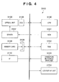
- FIG. 4 is a block diagram showing the arrangement of the DSC (digital camera) 3012 according to the embodiment.
- a CPU 3100 controls the entire DSC 3012 .
- a ROM 3101 stores the process procedure of the CPU 3100 .
- a RAM 3102 serves as the work area of the CPU 3100 .
- Switches 3103 to execute various kinds of operations include a shutter switch, mode change-over switch, selection switch, and cursor keys.
- a liquid crystal display unit 2700 is used to display an image that is currently being captured or an image captured and stored in a memory card, or display menus for various kinds of settings.
- An optical unit 3105 mainly has a lens and its driving system. Reference numeral 3106 denotes a CCD element.
- a driver 3107 drives and controls the optical unit 3105 under the control of the CPU 3100 .
- a connector 3108 connects a storage medium 3109 (e.g., compact Flash® memory card or smart media).
- a USB interface (slave side of USB) 3110 connects to a PC or the PD printer 1000 of the embodiment.
- FIG. 5 is a sequence chart for explaining a rough signal flow when the DSC 3012 issues a print request to the PD printer 1000 to execute printing in the above-described printing system according to the embodiment.
- This process procedure is executed after the PD printer 1000 and DSC 3012 connect to each other via a USB cable or mutually confirm by wireless communication that they comply with DPS specifications.
- the DSC 3012 transmits “ConfigurePrintService” to the PD printer 1000 to confirm the state of the PD printer 1000 ( 600 ).
- the PD printer 1000 returns its state (“idle” state) at that point in time ( 601 ). Since the PD printer 1000 is in the “idle” state, the DSC 3012 inquires the PD printer 1000 of its Capability ( 602 ) and issues a print start request (StartJob) corresponding to Capability ( 603 ).
- the DSC 3012 issues the print start request to the PD printer 1000 under the condition that “newJobOK” in status information (to be described later) from the PD printer 1000 is “True” in 601 .
- the PD printer 1000 requests, based on the file ID of image data as a print instruction target, file information as various kinds of attribute information including a file name and an image capturing date/time of the DSC 3012 (GetFileInfo) ( 604 ).
- file information contains information of, for example, a file capacity.
- the PD printer 1000 requests the file information of the DSC 3012 (GetFile) ( 605 ).
- the DSC 3012 sends the image data (ImageFile) of the requested file to the PD printer 1000 .
- the PD printer 1000 starts a print process and sends status information indicating “Printing” to the DSC 3012 by “NotifyDeviceStatus” in 606 .
- the PD printer 1000 notifies the DSC of it by “NotifyJobStatus” 607 at the start of process of the next page. If the number of print target pages is only one, and the print-requested page is printed, the PD printer 1000 notifies the DSC that the PD printer 1000 is set in the “idle” state by “NotifyDeviceStatus” 608 (NotifyDeviceStatus (Idle)).
- the PD printer 1000 sends the “NotifyJobStatus” 607 to the DSC 3012 every time N images are printed.
- the issue timings of “NotifyJobStatus” and “NotifyDeviceStatus” and the image data acquisition timing of this embodiment are merely examples. Various cases can occur depending on implementation of the product.
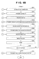
- FIGS. 6A and 6B are flowcharts for explaining a process of executing communication between the digital camera (DSC) 3012 and the PD printer 1000 according to the embodiment of the present invention to supply image data from the DSC 3012 to the PD printer 1000 and execute printing.
- steps S 1 to S 15 indicate the process of the DSC 3012
- steps S 21 to S 31 indicate the process of the PD printer 1000 .
- the DSC 3012 and PD printer 1000 mutually confirm that they comply with the DPS specifications.
- the DSC 3012 inquires the PD printer 1000 of the printer state and device information.
- the PD printer 1000 notifies the DSC of its state and device information at that point in time.
- the device information includes, for example, the version of the connection protocol and the vender name and model name of the printer.
- the DSC 3012 stores, in the RAM 3102 , necessary “information 1” of the printer state and device information.
- the “information 1” contains information that is necessary for the DSC 3012 to convert an image file at a later time.
- the DSC 3012 requests Capability of the PD printer 1000 , as indicated by 602 in FIG. 5 .
- step S 22 the PD printer 1000 creates capability information (Capability) about its print function and transmits it to the DSC 3012 .
- the DSC 3012 receives Capability (step S 3 ).
- step S 4 the DSC 3012 forms a UI based on Capability and displays it on the display unit 2700 .
- the display unit 2700 displays a UI window that allows the user to arbitrarily select the items and inhibits selection of other items.
- step S 5 the user of the DSC 3012 selects images to be printed by referring to the formed UI window and sets the print format of the images.
- the print format of images is set based on Capability of the PD printer 1000 received in step S 3 , including the number of pages to be printed, paper size, layout, and ON/OFF of date print.
- step S 6 “information 2” thus set by the user is stored in the RAM 3102 .
- the “information 2” contains the information of the paper size and layout set by the user using the UI.
- step S 7 When the user gives the instruction for the start of printing by using the UI, the process advances to step S 7 to create a print job file to instruct printing.
- step S 8 the DSC 3012 transmits the created print job file to the PD printer 1000 .
- step S 23 the PD printer 1000 receives the print job file.
- step S 24 the PD printer 1000 analyzes the received print job file and prepares for printing. The PD printer 1000 issues an “image file information acquisition request” (image file name) of the print target described in the print job file to the DSC 3012 .
- the “image file information acquisition request” corresponds to “GetObjectInfo” defined by the PTP.
- the role of the “image file information acquisition request” of this embodiment is to transmit an image file creation timing from the PD printer 1000 to the DSC 3012 .
- the “image file information acquisition request” is used as the means for transmitting the creation timing.
- the means is not limited to this. Any other dedicated command or an existing communication command may be used.
- the PD printer 1000 notifies the DSC 3012 of the timing of “print image file creation”.
- step S 9 the DSC 3012 receives the “image file information acquisition request”.
- the process advances to step S 10 to execute a process of creating a print image file to be transmitted to the PD printer 1000 as a characteristic feature of this embodiment.
- the process in step S 10 will be described later in detail.
- step S 11 the DSC 3012 transmits the information (ObjectInfo Dataset: including attribute information such as the image file name, data size, directory, and date) of the created print image file to the PD printer 1000 .
- step S 25 the PD printer 1000 receives the information of the print image file.
- the PD printer 1000 transmits, to the DSC 3012 , a request to acquire the designated print image file itself (step S 26 ).
- the DSC 3012 Upon receiving the image file acquisition request (step S 12 ), the DSC 3012 transmits the requested print image file to the PD printer 1000 in step S 13 .
- step S 27 the PD printer 1000 receives the print image file.
- step S 28 the image data of the received image file is decoded and subjected to an image process to convert the data into an image with a format that can be output by the PD printer 1000 .
- step S 29 the PD printer 1000 prints based on the converted image data.
- step S 30 it is determined whether the image data is completely printed. If printing is not completed, for example, the PD printer 1000 may be unable to ensure a sufficient buffer area to store the received image data and may have divisionally received and processed the image data of the image file in step S 27 . In such a case, the process returns to step S 24 to transmit the “image file information acquisition request” to the DSC 3012 again.
- step S 27 the partial data of the image data of the image file is received and printed in accordance with the same procedure as described above.
- step S 30 If the image data of the image file is completely printed in step S 30 , the process advances to step S 31 to notify the DSC 3012 of the completion of printing of the image file.
- the DSC 3012 Upon receiving the print completion notification, the DSC 3012 deletes the print image file created in step S 10 from the RAM 3102 (step S 15 ) and finishes the process. The original image file in the memory card 3109 is kept saved.
- step S 29 If the amount of the acquired image data is insufficient in step S 29 described above and, for example, if the data amount is smaller than that printed by one cycle of scanning of the printhead, the image process in step S 28 is possible though the print process in step S 29 is impossible. In this case, the determination in step S 30 is done without executing the print operation in step S 29 , and the process returns to step S 24 .
- the DSC 3012 transmits the “image file information” to the PD printer 1000 in step S 11 .
- This is a reply to the “image file information acquisition request” (GetObjectInfo) (step S 24 ) from the PD printer 1000 in step S 24 described above.
- the “image file information” also has a role to notify the PD printer 1000 of completion of the image file conversion and creation process by the DSC 3012 , like the above-described “image file information acquisition request”.
- any other dedicated command or an existing communication command may be used.
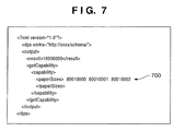
- FIG. 7 depicts a view showing an example of a “schema” as an example of Capability information transmitted from the PD printer 1000 to the DSC 3012 in step S 22 in FIG. 6B .
- the schema describes paper sizes (paperSizes) usable by the PD printer 1000 .
- “ ⁇ paperSizes>80010000 80010001 80010002” indicated by reference numeral 700 in FIG. 7 is paper size information.
- the PD printer 1000 of this embodiment can print by using paper sheets of three sizes, that is, “A4”, “L”, and “2L”.
- the three 8-digit number strings “80010000”, “80010001”, and “80010002” indicated by reference numeral 700 correspond to the paper sizes “A4”, “L”, and “2L”, respectively.
- the correspondence between the number strings and the paper sizes is set in advance between the PD printer 1000 and the DSC 3012 .
- the DSC 3012 can know the paper sizes usable for printing by the PD printer 1000 by receiving the schema.
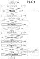
- FIG. 8 is a flowchart for explaining the image file creation process (step S 10 ) by the DSC according to the embodiment.
- step S 41 the DSC 3012 reads out the image data of the process target image file stored in the memory card 3019 .
- step S 42 it is determined whether the process such as resize (reduction), rotation, and color conversion is necessary for the image data. For example, the resolution and memory capacity of the PD printer 1000 are acquired based on “information 1” stored in the RAM 3102 in step S 2 described above. In addition, the resolution and size of the image to be actually printed are acquired based on “information 2” stored in step S 6 . It is then determined whether the process is necessary for the print target image data.
- the resolution of the image data of the original image file is 8,000,000 pixels
- the print resolution of the PD printer 1000 is 720 dpi
- the size of the image to be printed is about 3 ⁇ 5 cm.
- the DSC 3012 should reduce (resize) the image data and then transmit it to the PD printer 1000 , instead of directly transferring the original image data having 8,000,000 pixels.
- step S 42 If it is determined in step S 42 that the original image data requires certain conversion, the process advances to step S 43 . Otherwise, the process is ended without any operation.
- step S 43 The original image file is encoded by, for example, JPEG.
- step S 43 the data is converted into raw image data by decoding.
- step S 44 it is determined whether resize of the image is necessary. If the result is YES in step S 44 , the process advances to S 45 to reduce the image data. After step S 45 is executed, or if it is determined in step S 44 that resize of the image is unnecessary, the process advances to step S 46 to determine whether rotation of the image is necessary. If the result is YES in step S 46 , the image data is rotated in step S 47 , and the process advances to step S 48 . Otherwise, the process directly advances to step S 48 .
- step S 48 it is determined whether color conversion of the image data is necessary. If the result is NO in step S 48 , the process advances to step S 50 . If the result is YES in step S 48 , color conversion of the image data is executed in step S 49 , and the process advances to step S 50 .
- step S 50 the processed image data is encoded by JPEG again.
- the process advances to step S 51 to check whether the image data has an “EXIF” tag. If the result is YES in step S 51 , the “EXIF” tag is updated in step S 52 in accordance with the contents of conversion in step S 45 , S 47 , and S 49 . If the image data has no “EXIF” tag in step S 51 , the process advances to step S 53 to add, for example, orientation information representing the orientation of the image and necessary information including the image size after conversion to the image data as an “EXIF” tag.
- An image orientation (tag number “ 274 ”: Orientation) is defined as appendix information of TIFFRev.6.0 used in EXIF.
- “1” (default) defines that “the 0th row is located on the upper edge of the image when observed with eyes, and the 0th column is located on the right left edge of the image when observed with eyes”.
- the image orientation of the “EXIF” tag of the image changes to “8”, that is, “the 0th row is located on the left edge of the image when observed with eyes, and the 0th column is located on the lower edge of the image when observed with eyes”.
- the “EXIF” tag see the “digital still camera image format standard (Exit)” in the JEIDA standard.
- the DSC 3012 acquires the “information 1” such as the device information of the printer.
- the DSC 3012 also acquires the “information 2”, that is, information set by the camera user based on the UI corresponding to the functions of the printer and stores the information in the memory.
- the DSC 3012 can create print target image data based on these pieces of information and transmit it to the printer.
- the image data to be transmitted from the camera to the printer can obtain an amount and format corresponding to the print conditions in the printer. This reduces the load required for the image data process in the printer and also decreases the memory capacity used by the printer for the image data process. Additionally, the time required for image data transmission can be shortened because the image data can be reduced in advance in accordance with printing by the printer and transmitted to the printer.
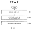
- FIG. 9 is a flowchart for explaining the image data process (step S 28 in FIG. 6B ) by the PD printer 1000 according to the embodiment.
- step S 61 the PD printer 1000 decodes the image data received from the DSC 3012 .
- step S 62 in order to output the decoded data to the printhead (inkjet head) of the printer engine 3004 , the image data is rearranged.
- step S 63 the rearranged data is rasterized in the print buffer (provided in the memory 3003 ).
- the image data process by the PD printer 1000 need not include resize, rotation, and color conversion of the image data. For this reason, the image process by the PD printer 1000 is simple, and the load on the PD printer 1000 can be reduced.
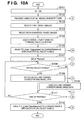
- FIGS. 10A and 10B are flowcharts for explaining the processes of a DSC 3012 and a PD printer 1000 in a printing system according to the first embodiment of the present invention.
- a process such as rotation or resize
- a print job that designates a process target image by a virtual object handle is issued and printed.
- the DSC 3012 executes the process in steps S 101 to S 112
- the PD printer 1000 executes the process in steps S 121 to S 131 .
- the programs to cause the DSC 3012 and PD printer 1000 to execute the processes are stored in a ROM 3101 of the DSC 3012 and a program memory 3003 a of the PD printer 1000 , respectively.
- Step S 101 corresponds to the process in steps S 1 to S 6 in FIG. 6A .
- Step S 121 corresponds to the process in steps S 21 and S 22 in FIG. 6B .
- the DSC 3012 executes rotation and resize of an image as an image process.
- the process may further include, for example, color conversion of an image.
- step S 102 the DSC 3012 transmits, to the PD printer 1000 , the list of the real object handles of all images stored in a memory card 3109 .
- step S 122 the PD printer 1000 receives the list and grasps all images stored in the memory card 3109 of the DSC 3012 as the communication partner.
- step S 103 a user selects print target images from all images stored in the memory card 3109 by using the UI of the DSC 3012 .
- step S 104 the user selects images that require rotation and/or resize from the selected print target images. This selection may be done automatically. In this case, whether rotation or resize is necessary is determined by using any of the above-described selection criteria by, for example, referring to the aspect ratio of each image and that of a print paper sheet.
- step S 105 a virtual object handle is assigned to each image selected in step S 104 as a rotation/resize target.
- a virtual object handle is a new object handle that is not assigned to, for example, a file in the memory card 3109 .
- step S 106 the DSC 3012 issues PTP_Event “ObjectAdded” to the PD printer 1000 in correspondence with each of the object handles that are set as virtual object handles. “ObjectAdded” notifies the PD printer 1000 of the existence of a virtual object handle except the object handle transmitted in step S 102 .
- step S 123 the PD printer 1000 receives “ObjectAdded” and registers the virtual object handle. This makes it possible to designate the image by using the virtual object handle in the subsequent process.
- step S 107 the DSC 3012 issues a print job (StartJob) to the PD printer 1000 .
- the print job includes the real object handles and virtual object handles based on the user selection process using the UI in steps S 103 and S 104 .
- StartJob designates not a virtual object handle but a real object handle for an image that requires no rotation and/or resize.
- step S 124 the PD printer 1000 receives the print job and starts executing it.
- step S 125 the PD printer 1000 requests the image data contained in the print job of the DSC 3012 by using each object handle (GetObjectInfo and GetObject).
- the DSC 3012 Upon receiving the request, the DSC 3012 checks in step S 108 whether the object handle of the requested image is a virtual object handle. If the object handle is a virtual object handle, the process advances to step S 109 to read out and decode image data having a real object handle corresponding to the virtual object handle. Then, the image data is resized and/or rotated. The resized and/or rotated image data is encoded and transmitted to the PD printer 1000 .
- the rotation and resize process executed by the DSC 3012 is the same as in FIGS. 6A , 6 B and FIG. 8 , and a description thereof will be omitted.
- step S 110 the process advances to step S 110 to read out image data corresponding to the real object handle and transmit the data to the PD printer 1000 .
- step S 109 or S 110 the process advances to step S 111 to check whether a print completion notification is received from the PD printer 1000 . If printing is not ended yet, the process returns to step S 108 to wait for reception of the next image request. If a print completion notification is received in step S 111 , the process advances to step S 112 to issue PTP_Event “ObjectRemoved” in correspondence with each virtual object handle. This erases the virtual object handles unique to the print job and data added to them, which are registered in the PD printer 1000 .
- the PD printer 1000 requests the image data in step S 125 and receives the image data transmitted from the DSC 3012 (in step S 109 or S 110 ) in step S 126 .
- step S 127 the image data is decoded, rasterized to print data, and printed.
- step S 128 it is determined whether all images contained in the print job are printed. If the result is NO in step S 128 , the process returns to step S 125 to execute the above-described process. If printing is ended in step S 128 , the process advances to step S 129 to notify the DSC 3012 of completion of printing.
- PTP_Event “ObjectRemoved” is received. The process advances to step S 131 to erase the virtual object handles registered in step S 123 . If image data are cached in correspondence with the virtual object handles, the cached image data are erased.
- the DSC 3012 issues a print job in which actual image data is specified by a real object handle while an image to be subjected to rotation and/or resize by the DSC 3012 is specified by a virtual object handle.
- the DSC 3012 can determine whether each image data requires rotation and/or resize and execute a suitable process.
- FIG. 11 depicts a view for explaining an example of print layout to be printed by the printing system according to the first embodiment of the present invention.
- four images A to D are printed on one paper sheet.
- the images A to D are different images, all of which are recorded in the memory card 3109 in a landscape format. In printing the images A to D, an instruction is issued to print them in a portrait format. Hence, all the images A to D require rotation. According to the above-described first embodiment, a virtual object handle is assigned to each of the images A to D in step S 105 in FIG. 10A .
- FIG. 12 depicts a view for explaining generation and disappearance of rotation and/or resize image files in the PD printer 1000 according to the first embodiment.
- the DSC 3012 can rotate and/or resize one image by using a memory 3102 .
- image data generated immediately before must be erased from the memory 3102 .
- step S 4401 in FIG. 12 a rotated image of the image A is generated in response to a request from the PD printer 1000 .
- “ ⁇ ” indicates that the image is generated.
- step S 4402 a rotated image of the image B is generated in response to a request from the PD printer 1000 .
- the rotated image data of the image A generated in step S 4401 is erased from the memory 3102
- “x” indicates that the image is erased (discarded).
- step S 4403 a rotated image of the image A is generated again in response to a request from the PD printer 1000 .
- step S 4403 the rotated image data of the image B generated in step S 4402 is erased. In this way, generation and discard of the rotated images of the images A and B are sequentially repeated in response to a request from the PD printer 1000 .
- the images A and B have been printed, printing of the images C and D starts in step S 4405 .
- step S 4405 a rotated image of the image C is generated in response to a request from the PD printer 1000 .
- the rotated image data of the image B generated in step S 4404 is erased from the memory 3102 .
- step S 4406 a rotated image of the image D is generated in response to a request from the PD printer 1000 .
- the rotated image data of the image C generated in step S 4405 is erased from the memory 3102 . In this way, generation and discard of the rotated images of the images C and D are sequentially repeated in response to a request from the PD printer 1000 .
- the process of the print job is ended.
- the DSC 3012 issues “ObjectRemoved” to the PD printer 1000 .
- the DSC 3012 issues no “ObjectRemoved”.
- the DSC 3012 preferably issues “ObjectRemoved” to the PD printer 1000 after the print job is processed. This is because if the DSC 3012 issues, to the PD printer 1000 , “ObjectRemoved” for the object handle of the print target during the progress of the print job, the PD printer 1000 may determine that the DSC 3012 cannot continue printing any longer.
- the virtual object handles are immediately discarded after completion of the print job to prevent the rotation and/or resize target images corresponding to the virtual object handles from being used for any purpose other than printing. No one can deny the possibility that the PTP Initiator may issue some PTP Operation for the rotation and/or resize target images corresponding to the virtual object handles.
- the memory card 3109 having a capacity to store 10 images is storing 10 images (real object handles 1 to 10), and virtual object handles (virtual object handles 11 to 20) are assigned to the images.
- the PD printer 1000 determines that the memory card 3109 is storing a total of 20 images (because the PD printer 1000 cannot determine the capacity of the memory card 3109 ).
- the PD printer 1000 may issue a command “MoveObject”, that is, a request to “move” the image of, for example, an object handle 1 to a virtual object handle 15 .
- the DSC 3012 must return a message “no sufficient memory card capacity remains” to the PD printer 1000 because the image movement in the memory card 3109 is impossible due to shortage in the remaining capacity of the memory card 3109 .
- the PD printer 1000 (Initiator) side does not assume the occurrence of the case “no sufficient memory card capacity remains” in the process of moving an object that should exist on the memory card 3109 . Hence, this error may impede subsequent communication. For this reason, the virtual object handles must be discarded immediately after completion of the print job.
- the means for implementing the purpose of “immediately discarding the virtual object handles” is not particularly limited to completion of the print job.
- the completion of printing of a page can be regarded as almost equivalent to the “completion of the print job” for a virtual object handle that has been printed on that page and would not be printed on subsequent pages.
- the DSC 3012 can determine virtual object handles that can be discarded by confirming the state of progress of the print job issued by the PD printer 1000 .
- the DSC 3012 can safely and reliably generate a print image requested by the PD printer 1000 and supply the print image to it by using a virtual object handle in printing.
- the print job determines assignment of virtual object handles, and then, the virtual object handles are deleted immediately after completion of the print job. For this reason, any access to the virtual object handles by an operation except the print job can be prevented.
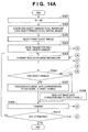
- FIGS. 13A and 13B are flowcharts for explaining the processes of a DSC 3012 and a PD printer 1000 in a printing system according to the second embodiment of the present invention.
- the DSC 3012 executes a process such as rotation or resize
- a print job that designates a process target image by a virtual object handle in a print object is issued and printed, as in the above-described first embodiment.
- the second embodiment is different from the above-described first embodiment in that the DSC 3012 sets virtual object handles for all images set as a print target. Referring to FIGS.
- the DSC 3012 executes the process in steps S 201 to S 212
- the PD printer 1000 executes the process in steps S 221 to S 231
- the programs to cause the DSC 3012 and PD printer 1000 to execute the processes are stored in a ROM 3101 of the DSC 3012 and a program memory 3003 a of the PD printer 1000 , respectively.
- Step S 201 corresponds to the process in steps S 1 to S 6 in FIG. 6A .
- Step S 221 corresponds to the process in steps S 21 and S 22 in FIG. 6B .
- the DSC 3012 executes rotation and resize of an image as an image process.
- the process may further include, for example, color conversion of an image.
- step S 202 the USC 3012 transmits, to the PD printer 1000 , the list of the real object handles of all images stored in a memory card 3109 .
- step S 222 the PD printer 1000 receives the list and grasps all images stored in the memory card 3109 of the DSC 3012 as the communication partner.
- step S 203 the user selects print target images from the images stored in the memory card 3109 by using the UI of the DSC 3012 .
- step S 204 virtual object handles are assigned to all the selected print target images.
- step S 205 the user selects images that require rotation and/or resize from the selected print target images. This selection may be done automatically. In this case, whether rotation or resize is necessary is determined by using any of the above-described selection criteria by, for example, referring to the aspect ratio of each image and that of a print paper sheet.
- step S 206 the DSC 3012 issues PTP_Event “ObjectAdded” to the PD printer 1000 in correspondence with each of the virtual object handles of the images selected in step S 204 as print targets.
- step S 223 the PD printer 1000 receives “ObjectAdded” and registers the virtual object handle. This makes it possible to designate the image by using the virtual object handle in the subsequent process.
- the process in step S 203 is unnecessary when all images stored in the memory card 3109 are to be printed. In this case, the real object handles and virtual object handles of all images stored in the memory card 3109 are transmitted in step S 202 .
- step S 207 the DSC 3012 issues a print job (StartJob) to the PD printer 1000 .
- the print job includes the real object handles and virtual object handles of the rotation and/or resize target images based on the user selection process using the UI in steps S 203 and S 205 .
- StartJob designates not a virtual object handle but a real object handle for an image that requires no rotation and/or resize.
- step S 224 the PD printer 1000 receives the print job and starts executing it.
- step S 225 the PD printer 1000 requests the image data contained in the print job of the DSC 3012 by using each object handle (GetObjectInfo and GetObject).
- the DSC 3012 Upon receiving the request, the DSC 3012 checks in step S 208 whether the object handle of the requested image is a virtual object handle. If the object handle is a virtual object handle, the process advances to step S 209 to read out and decode image data having a real object handle corresponding to the virtual object handle. Then, the image data is resized and/or rotated. The resized and/or rotated image data is encoded and transmitted to the PD printer 1000 .
- the rotation and resize process executed by the DSC 3012 is the same as in FIGS. 6A , 6 B and FIG. 8 , and a description thereof will be omitted.
- step S 210 the process advances to step S 210 to read out image data corresponding to the real object handle and transmit the data to the PD printer 1000 .
- step S 209 or S 210 the process advances to step S 211 to determine whether a print completion notification is received from the PD printer 1000 . If printing has not ended yet, the process returns to step S 208 to wait for reception of the next image request. If a print completion notification is received in step S 211 , the process advances to step S 212 to issue PTP_Event “ObjectRemoved” in correspondence with each virtual object handle. This erases the virtual object handles unique to the print job and data added to them, which are registered in the PD printer 1000 .
- the PD printer 1000 requests the image data in step S 225 and receives the image data transmitted from the DSC 3012 (in step S 209 or S 210 ) in step S 226 .
- step S 227 the image data is decoded, rasterized to print data, and printed.
- step S 228 it is determined whether all images contained in the print job are printed. If the result is NO in step S 228 , the process returns to step S 225 to execute the above-described process. If printing is ended in step S 228 , the process advances to step S 229 to notify the DSC 3012 of completion of printing.
- PTP_Event “ObjectRemoved” is received. The process advances to step S 231 to erase the virtual object handles registered in step S 223 . If image data are cached in correspondence with the virtual object handles, the cached image data are erased.
- a virtual object handle When a virtual object handle is assigned in accordance with communication connection between the DSC 3012 and the PD printer 1000 , access to the virtual object handle for any purpose other than direct printing can be prevented. It is preferable to prevent access to the virtual object handle from another host such as a PC. This is because “it may be impossible to ensure a sufficient memory card capacity for Move of an Object”, as described in the first embodiment. As another example, if a PC can access virtual object handles corresponding to all images in the memory card 3109 , the total image size corresponding to the real object handles and virtual object handles may exceed the capacity of the memory card 3109 (as in the above-described example). A host such as a PC may not expect a “state wherein images beyond the memory card capacity are saved”. This may impede connection to the PC after acquisition of unexpected information.
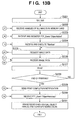
- FIGS. 14A and 14B are flowcharts for explaining the processes of a DSC 3012 and a PD printer 1000 in a printing system according to the third embodiment of the present invention.
- a virtual object handle is set as the object handle of a rotation and/or resize target image.
- the number of the virtual object handle is made discriminable from a real object handle.
- an odd number is assigned to a real object handle, and an even number is assigned to a virtual object handle.
- the DSC 3012 and PD printer 1000 need to cooperate, and the PD printer 1000 must know in advance which object handle is a virtual object handle. Referring to FIGS.
- the DSC 3012 executes the process in steps S 301 to S 310
- the PD printer 1000 executes the process in steps S 321 to S 330
- the programs to cause the DSC 3012 and PD printer 1000 to execute the processes are stored in a ROM 3101 of the DSC 3012 and a program memory 3003 a of the PD printer 1000 , respectively.
- Step S 301 corresponds to the process in steps S 1 to S 6 in FIG. 6A .
- Step S 321 corresponds to the process in steps S 21 and S 22 in FIG. 6B .
- the DSC 3012 executes rotation and resize of an image as an image process.
- the process may further include, for example, color conversion of an image.
- step S 302 odd real object handles and even virtual object handles are assigned to all images stored in a memory card 3109 .
- step S 303 the user selects print target images from the images stored in the memory card 3109 by using the UI of the DSC 3012 .
- step S 304 the DSC 3012 issues, to the PD printer 1000 , a print job (StartJob) including real object handles based on the user selection process using the UI in step S 303 .
- StartJob a print job including real object handles based on the user selection process using the UI in step S 303 .
- step S 322 the PD printer 1000 receives the print job and starts executing it.
- step S 323 the PD printer 1000 requests the information of an image contained in the print job of the DSC 3012 by using each object handle (GetObjectInfo) Upon receiving the request, the DSC 3012 transmits the requested image information (ObjectInfo) to the PD printer 1000 in step S 305 .
- step S 324 the PD printer 1000 receives the image information and determines based on the information whether the image data of the image requires rotation and/or resize.
- step S 325 to request, of the DSC 3012 , image data corresponding to an object handle obtained by incrementing the number of the object handle of the image by one (GetObject). If it is determined in step S 324 that rotation and/or resize is unnecessary, the process advances to step S 326 to request image data corresponding to the object handle (GetObject).
- the DSC 3012 determines in step S 306 whether the number of the object handle is an odd number (real object handle). If the object handle has an odd number, the process advances to step S 308 to read out image data corresponding to object handle (real object handle). Then, the process advances to step S 309 . If the number of the object handle is not an odd number in step S 306 , the process advances to step S 307 to read out image data corresponding to a real object handle obtained by decrementing the number of the received object handle by one and decode the image data. The image data is resized and/or rotated. The resized and/or rotated image data is encoded, the process advances to step S 309 .
- step S 309 the encoded image data is transmitted to the PD printer 1000 .
- the rotation and resize process executed by the DSC 3012 is the same as in FIGS. 6A , 6 B and FIG. 8 , and a description thereof will be omitted.
- the process advances to step S 310 to determine whether a print completion notification is received from the PD printer 1000 . If the printing has not ended yet, the process returns to step S 305 to wait for reception of the next image request. If a print completion notification is received in step S 310 , the process is ended.
- the PD printer 1000 After requesting image data in step S 325 or S 326 , the PD printer 1000 receives the image data transmitted from the DSC 3012 in step S 327 .
- step S 328 the received image data is decoded, rasterized to print data, and printed.
- step S 329 it is determined whether all images contained in the print job are printed. If the result is NO in step S 329 , the process returns to step S 323 to execute the above-described process. If the printing has ended in step S 329 , the process advances to step S 330 to notify the DSC 3012 of completion of printing.
- the DSC 3012 and PD printer 1000 must share the object handle assignment rule.
- any existing method can be used. For example, the vender name or device name of the connection partner is used, or a keyword unique to the rule is exchanged.
- step S 302 no rotated or resized image data corresponding to an even object handle is present in the DSC 3012 . Only original image data corresponding to an odd object handle is present.
- the PD printer 1000 determines whether rotation and/or resize of an image is necessary and executes the process. Hence, the DSC 3012 can more safely and reliably generate a print image suitable for the PD printer 1000 .
- rotation images and non-rotation images are assigned to even object handles and odd object handles, respectively.
- the assignment rule is not limited to this.
- a number of (rotation image+X) may be assigned to a non-rotation image (X is an arbitrary integer).
- Rotation/non-rotation of an image may be designated by a specific bit of an object handle. That is, any method can be used if it can associate a rotation and/or resize image with a corresponding original image.
- the description of the third embodiment has been done assuming that both devices mutually recognize that they share the assignment rule. However, sharing of the assignment rule is not always necessary. It is sufficient that the PD printer 1000 recognizes that the DSC 3012 is a “device that supports the assignment rule”. The DSC 3012 can operate in accordance with the assignment rule without knowing whether the PD printer 1000 as the connection partner is a “device that supports the assignment rule”. This is because a PD printer 1000 supporting the assignment rule requests image data by using an even object handle as needed. A PD printer 1000 that does not support the assignment rule always requests image data by using an odd object handle.
- the objects of the present invention are also achieved by supplying a storage medium which records software program codes to implement the functions of the embodiments to a system or apparatus and causing the computer (or CPU or MPU) of the system or apparatus to read out and execute the program codes.
- the program codes read out from the storage medium themselves implement the functions of the above-described embodiments.
- the storage medium that stores the program codes constitutes the present invention. Examples of the storage medium to supply the program codes are a Floppy® disk, hard disk, optical disk, magnetooptical disk CD-ROM, CD-R, magnetic tape, nonvolatile memory card, and ROM.
Landscapes
- Engineering & Computer Science (AREA)
- Theoretical Computer Science (AREA)
- Physics & Mathematics (AREA)
- General Physics & Mathematics (AREA)
- Human Computer Interaction (AREA)
- General Engineering & Computer Science (AREA)
- Signal Processing (AREA)
- Multimedia (AREA)
- Mathematical Physics (AREA)
- Quality & Reliability (AREA)
- Television Signal Processing For Recording (AREA)
- Record Information Processing For Printing (AREA)
- Studio Devices (AREA)
- Accessory Devices And Overall Control Thereof (AREA)
- Facsimile Image Signal Circuits (AREA)
Priority Applications (1)
| Application Number | Priority Date | Filing Date | Title |
|---|---|---|---|
| US12/846,229 US7929172B2 (en) | 2004-10-21 | 2010-07-29 | Image supply device, control method of the device, and printing system |
Applications Claiming Priority (3)
| Application Number | Priority Date | Filing Date | Title |
|---|---|---|---|
| JP2004-306899 | 2004-10-21 | ||
| JP2004306899A JP4262186B2 (ja) | 2004-10-21 | 2004-10-21 | 画像供給装置及び該装置の制御方法及び印刷システム |
| PCT/JP2005/019409 WO2006043667A1 (ja) | 2004-10-21 | 2005-10-21 | 画像供給装置及び該装置の制御方法及び印刷システム |
Related Parent Applications (1)
| Application Number | Title | Priority Date | Filing Date |
|---|---|---|---|
| PCT/JP2005/019409 Continuation WO2006043667A1 (ja) | 2004-10-21 | 2005-10-21 | 画像供給装置及び該装置の制御方法及び印刷システム |
Related Child Applications (1)
| Application Number | Title | Priority Date | Filing Date |
|---|---|---|---|
| US12/846,229 Division US7929172B2 (en) | 2004-10-21 | 2010-07-29 | Image supply device, control method of the device, and printing system |
Publications (2)
| Publication Number | Publication Date |
|---|---|
| US20070182993A1 US20070182993A1 (en) | 2007-08-09 |
| US7821663B2 true US7821663B2 (en) | 2010-10-26 |
Family
ID=36203080
Family Applications (2)
| Application Number | Title | Priority Date | Filing Date |
|---|---|---|---|
| US11/736,340 Expired - Fee Related US7821663B2 (en) | 2004-10-21 | 2007-04-17 | Image supply device, control method of the device, and printing system |
| US12/846,229 Expired - Fee Related US7929172B2 (en) | 2004-10-21 | 2010-07-29 | Image supply device, control method of the device, and printing system |
Family Applications After (1)
| Application Number | Title | Priority Date | Filing Date |
|---|---|---|---|
| US12/846,229 Expired - Fee Related US7929172B2 (en) | 2004-10-21 | 2010-07-29 | Image supply device, control method of the device, and printing system |
Country Status (5)
| Country | Link |
|---|---|
| US (2) | US7821663B2 (enExample) |
| JP (1) | JP4262186B2 (enExample) |
| KR (1) | KR100899149B1 (enExample) |
| CN (1) | CN101044447B (enExample) |
| WO (1) | WO2006043667A1 (enExample) |
Cited By (2)
| Publication number | Priority date | Publication date | Assignee | Title |
|---|---|---|---|---|
| US20070260809A1 (en) * | 2004-09-16 | 2007-11-08 | Kenichiroh Hara | Communication Between Image-Related Apparatus and Information Apparatus |
| US20220311893A1 (en) * | 2020-01-17 | 2022-09-29 | Sharp Kabushiki Kaisha | Image forming apparatus, recording medium recording control program, and control method |
Families Citing this family (15)
| Publication number | Priority date | Publication date | Assignee | Title |
|---|---|---|---|---|
| US7561288B2 (en) * | 2002-07-05 | 2009-07-14 | Canon Kabushiki Kaisha | Recording system and controlling method therefor |
| JP4367941B2 (ja) * | 2005-01-25 | 2009-11-18 | キヤノン株式会社 | 中継装置、画像供給装置及び印刷システムとその制御方法 |
| JP4979281B2 (ja) * | 2006-06-19 | 2012-07-18 | キヤノン株式会社 | 画像処理装置及びその制御方法と画像処理システム |
| JP4781200B2 (ja) * | 2006-08-10 | 2011-09-28 | キヤノン株式会社 | デジタルカメラ、デジタルカメラの制御方法、プログラム、記憶媒体、画像処理装置 |
| US7973950B1 (en) * | 2007-02-16 | 2011-07-05 | Adobe Systems Incorporated | Image printing history |
| JP2009212743A (ja) * | 2008-03-04 | 2009-09-17 | Sony Corp | 電子機器、送信方法及びプログラム |
| CN101576908A (zh) * | 2009-03-12 | 2009-11-11 | 北京中星微电子有限公司 | 一种通过文件名获取文件句柄的方法及系统 |
| US8610928B2 (en) * | 2010-02-09 | 2013-12-17 | Apple Inc. | Framework that supports driverless printing |
| US8610927B2 (en) | 2010-02-09 | 2013-12-17 | Apple Inc. | Walk-up printing without drivers |
| US20120050768A1 (en) * | 2010-08-30 | 2012-03-01 | Samsung Electronics Co., Ltd. | Color image forming apparatus and control board included in the same |
| US8953058B2 (en) * | 2011-06-29 | 2015-02-10 | Fotonation Limited | Axial chromatic aberration correction |
| US8675215B2 (en) | 2012-01-31 | 2014-03-18 | Apple Inc. | Using regions of interest to scale print data for print jobs |
| US9298401B2 (en) | 2012-02-03 | 2016-03-29 | Apple Inc. | Configuring print jobs associated with unsupported document formats |
| US8891115B2 (en) | 2012-02-03 | 2014-11-18 | Apple Inc. | Configuration of print data for print jobs based on document-processing capabilities of printers |
| WO2020237581A1 (zh) * | 2019-05-30 | 2020-12-03 | 华为技术有限公司 | 使用终端设备打印虚拟机中的文件的方法、装置及系统 |
Citations (14)
| Publication number | Priority date | Publication date | Assignee | Title |
|---|---|---|---|---|
| JPH0832911A (ja) | 1994-07-20 | 1996-02-02 | Olympus Optical Co Ltd | カメラシステム |
| JPH10290470A (ja) | 1997-04-04 | 1998-10-27 | Eastman Kodak Co | ホストカメラによるプリンタパラメータ補償 |
| US20010013894A1 (en) | 1997-04-04 | 2001-08-16 | Eastman Kodak Company | Digital camera providing image processing for an attachable printer |
| JP2003134457A (ja) | 2001-10-29 | 2003-05-09 | Fuji Photo Film Co Ltd | 電子カメラ |
| US20030156196A1 (en) | 2002-02-21 | 2003-08-21 | Canon Kabushiki Kaisha | Digital still camera having image feature analyzing function |
| JP2003250108A (ja) | 2002-02-22 | 2003-09-05 | Canon Inc | 画像記録装置及び画像記録システムとその制御方法 |
| EP1389000A2 (en) | 2002-08-05 | 2004-02-11 | Canon Kabushiki Kaisha | Digital camera and printer |
| US20040252335A1 (en) | 2003-01-31 | 2004-12-16 | Canon Kabushiki Kaisha | Recording apparatus, communication apparatus, recording system, and control method therefor |
| US20050219555A1 (en) | 2004-01-30 | 2005-10-06 | Canon Kabushiki Kaisha | Printing system, printing method, image capturing apparatus, image processing method, storage medium, and program |
| US20060044395A1 (en) | 2002-11-29 | 2006-03-02 | Canon Kabushiki Kaisha | Image supply device, recording system, and recording control method |
| US20060072895A1 (en) | 2003-01-31 | 2006-04-06 | Canon Kabushiki Kaisha | Image supply device, recording apparatus, recording system, and control method therefor |
| US20060098938A1 (en) | 2003-01-31 | 2006-05-11 | Fumihiro Goto | Image supply device, recording system, and control method therefor |
| US20070195362A1 (en) | 2006-02-20 | 2007-08-23 | Canon Kabushiki Kaisha | Image-providing apparatus, image-printing apparatus and image-printing system comprised thereof |
| US7589862B2 (en) * | 2003-10-10 | 2009-09-15 | Canon Kabushiki Kaisha | Information processing apparatus and method for processing information for density correction |
Family Cites Families (2)
| Publication number | Priority date | Publication date | Assignee | Title |
|---|---|---|---|---|
| JP3901542B2 (ja) | 2002-02-22 | 2007-04-04 | シャープ株式会社 | 無線ネットワークシステム及び端末装置 |
| JP4908967B2 (ja) | 2006-08-10 | 2012-04-04 | キヤノン株式会社 | 画像入力装置、画像出力装置及び転送方法 |
-
2004
- 2004-10-21 JP JP2004306899A patent/JP4262186B2/ja not_active Expired - Fee Related
-
2005
- 2005-10-21 CN CN2005800360699A patent/CN101044447B/zh not_active Expired - Fee Related
- 2005-10-21 WO PCT/JP2005/019409 patent/WO2006043667A1/ja not_active Ceased
- 2005-10-21 KR KR1020077011188A patent/KR100899149B1/ko not_active Expired - Fee Related
-
2007
- 2007-04-17 US US11/736,340 patent/US7821663B2/en not_active Expired - Fee Related
-
2010
- 2010-07-29 US US12/846,229 patent/US7929172B2/en not_active Expired - Fee Related
Patent Citations (17)
| Publication number | Priority date | Publication date | Assignee | Title |
|---|---|---|---|---|
| JPH0832911A (ja) | 1994-07-20 | 1996-02-02 | Olympus Optical Co Ltd | カメラシステム |
| JPH10290470A (ja) | 1997-04-04 | 1998-10-27 | Eastman Kodak Co | ホストカメラによるプリンタパラメータ補償 |
| US20010013894A1 (en) | 1997-04-04 | 2001-08-16 | Eastman Kodak Company | Digital camera providing image processing for an attachable printer |
| US6940541B1 (en) | 1997-04-04 | 2005-09-06 | Eastman Kodak Company | Printer parameter compensation by a host camera |
| JP2003134457A (ja) | 2001-10-29 | 2003-05-09 | Fuji Photo Film Co Ltd | 電子カメラ |
| US20030156196A1 (en) | 2002-02-21 | 2003-08-21 | Canon Kabushiki Kaisha | Digital still camera having image feature analyzing function |
| JP2003250108A (ja) | 2002-02-22 | 2003-09-05 | Canon Inc | 画像記録装置及び画像記録システムとその制御方法 |
| US20030174351A1 (en) | 2002-02-22 | 2003-09-18 | Canon Kabushiki Kaisha | Image printing apparatus, image printing system and control method |
| JP2004129221A (ja) | 2002-08-05 | 2004-04-22 | Canon Inc | デジタルカメラ及びプリンタ |
| EP1389000A2 (en) | 2002-08-05 | 2004-02-11 | Canon Kabushiki Kaisha | Digital camera and printer |
| US20060044395A1 (en) | 2002-11-29 | 2006-03-02 | Canon Kabushiki Kaisha | Image supply device, recording system, and recording control method |
| US20040252335A1 (en) | 2003-01-31 | 2004-12-16 | Canon Kabushiki Kaisha | Recording apparatus, communication apparatus, recording system, and control method therefor |
| US20060072895A1 (en) | 2003-01-31 | 2006-04-06 | Canon Kabushiki Kaisha | Image supply device, recording apparatus, recording system, and control method therefor |
| US20060098938A1 (en) | 2003-01-31 | 2006-05-11 | Fumihiro Goto | Image supply device, recording system, and control method therefor |
| US7589862B2 (en) * | 2003-10-10 | 2009-09-15 | Canon Kabushiki Kaisha | Information processing apparatus and method for processing information for density correction |
| US20050219555A1 (en) | 2004-01-30 | 2005-10-06 | Canon Kabushiki Kaisha | Printing system, printing method, image capturing apparatus, image processing method, storage medium, and program |
| US20070195362A1 (en) | 2006-02-20 | 2007-08-23 | Canon Kabushiki Kaisha | Image-providing apparatus, image-printing apparatus and image-printing system comprised thereof |
Non-Patent Citations (1)
| Title |
|---|
| International Preliminary Report on Patentability Application No. PCT/JP2005/019409 filed Aug. 2, 2007. |
Cited By (4)
| Publication number | Priority date | Publication date | Assignee | Title |
|---|---|---|---|---|
| US20070260809A1 (en) * | 2004-09-16 | 2007-11-08 | Kenichiroh Hara | Communication Between Image-Related Apparatus and Information Apparatus |
| US8280975B2 (en) * | 2004-09-16 | 2012-10-02 | Canon Kabushiki Kaisha | Image supply apparatus and imaging apparatus, an information processing apparatus and control method thereof, and communication system |
| US20220311893A1 (en) * | 2020-01-17 | 2022-09-29 | Sharp Kabushiki Kaisha | Image forming apparatus, recording medium recording control program, and control method |
| US11647138B2 (en) * | 2020-01-17 | 2023-05-09 | Sharp Kabushiki Kaisha | Image forming apparatus, recording medium recording control program, and control method |
Also Published As
| Publication number | Publication date |
|---|---|
| JP4262186B2 (ja) | 2009-05-13 |
| US20100309520A1 (en) | 2010-12-09 |
| KR20070067224A (ko) | 2007-06-27 |
| US20070182993A1 (en) | 2007-08-09 |
| CN101044447B (zh) | 2012-08-29 |
| JP2006119892A (ja) | 2006-05-11 |
| WO2006043667A1 (ja) | 2006-04-27 |
| KR100899149B1 (ko) | 2009-05-26 |
| CN101044447A (zh) | 2007-09-26 |
| US7929172B2 (en) | 2011-04-19 |
Similar Documents
| Publication | Publication Date | Title |
|---|---|---|
| US7821663B2 (en) | Image supply device, control method of the device, and printing system | |
| US7430054B2 (en) | Printing apparatus, control method therefor, and storage medium | |
| US7515309B2 (en) | Recording apparatus, communication apparatus, recording system, and control method therefor | |
| US7916340B2 (en) | Print system, an image supply apparatus and control methods thereof | |
| AU2002334427A1 (en) | Printing apparatus, control method therefor, and storage medium | |
| US7990555B2 (en) | Image supply device and control method thereof and printing system | |
| US7907291B2 (en) | Image supply device and control method of the same and printing system | |
| US7289141B2 (en) | Image supply device, recording apparatus, recording system, and control method therefor | |
| US8130406B2 (en) | Recording apparatus image supply device and recording system and control method and program for image layout determination | |
| US20060039020A1 (en) | Image supply device, control method thereof and printing system | |
| JP4709246B2 (ja) | 画像供給デバイス及び該デバイスの制御方法及び印刷システム | |
| JP4612822B2 (ja) | 画像供給デバイス及び該デバイスの制御方法及び印刷システム | |
| JP4343858B2 (ja) | 印刷システム、印刷装置、及び印刷方法、並びに画像処理装置 | |
| JP4350615B2 (ja) | 画像供給デバイス及び該デバイスの制御方法及び印刷システム | |
| JP4047147B2 (ja) | 記録装置およびその制御方法 | |
| JP2008073882A (ja) | ダイレクトプリントシステム | |
| JP2006086588A (ja) | 画像供給デバイス及び該デバイスの制御方法及び印刷システム | |
| JP2006086587A (ja) | 画像供給デバイス及び該デバイスの制御方法及び印刷システム | |
| JP2007004715A (ja) | 画像供給デバイス及び該デバイスの制御方法及び印刷システム | |
| JP2010141575A (ja) | 印刷システム、画像供給デバイス及びその制御方法 |
Legal Events
| Date | Code | Title | Description |
|---|---|---|---|
| AS | Assignment |
Owner name: CANON KABUSHIKI KAISHA, JAPAN Free format text: ASSIGNMENT OF ASSIGNORS INTEREST;ASSIGNORS:YAMADA, AKITOSHI;KATO, MASAO;ONUMA, NOBUO;AND OTHERS;REEL/FRAME:019179/0916 Effective date: 20070412 |
|
| FEPP | Fee payment procedure |
Free format text: PAYOR NUMBER ASSIGNED (ORIGINAL EVENT CODE: ASPN); ENTITY STATUS OF PATENT OWNER: LARGE ENTITY |
|
| FPAY | Fee payment |
Year of fee payment: 4 |
|
| FEPP | Fee payment procedure |
Free format text: MAINTENANCE FEE REMINDER MAILED (ORIGINAL EVENT CODE: REM.) |
|
| LAPS | Lapse for failure to pay maintenance fees |
Free format text: PATENT EXPIRED FOR FAILURE TO PAY MAINTENANCE FEES (ORIGINAL EVENT CODE: EXP.); ENTITY STATUS OF PATENT OWNER: LARGE ENTITY |
|
| STCH | Information on status: patent discontinuation |
Free format text: PATENT EXPIRED DUE TO NONPAYMENT OF MAINTENANCE FEES UNDER 37 CFR 1.362 |
|
| FP | Lapsed due to failure to pay maintenance fee |
Effective date: 20181026 |