US7809979B2 - Storage control apparatus and method - Google Patents
Storage control apparatus and method Download PDFInfo
- Publication number
- US7809979B2 US7809979B2 US11/237,657 US23765705A US7809979B2 US 7809979 B2 US7809979 B2 US 7809979B2 US 23765705 A US23765705 A US 23765705A US 7809979 B2 US7809979 B2 US 7809979B2
- Authority
- US
- United States
- Prior art keywords
- storage device
- information
- restored
- disk
- area
- Prior art date
- Legal status (The legal status is an assumption and is not a legal conclusion. Google has not performed a legal analysis and makes no representation as to the accuracy of the status listed.)
- Expired - Fee Related, expires
Links
Images


Classifications
-
- G—PHYSICS
- G06—COMPUTING; CALCULATING OR COUNTING
- G06F—ELECTRIC DIGITAL DATA PROCESSING
- G06F3/00—Input arrangements for transferring data to be processed into a form capable of being handled by the computer; Output arrangements for transferring data from processing unit to output unit, e.g. interface arrangements
- G06F3/06—Digital input from, or digital output to, record carriers, e.g. RAID, emulated record carriers or networked record carriers
-
- G—PHYSICS
- G06—COMPUTING; CALCULATING OR COUNTING
- G06F—ELECTRIC DIGITAL DATA PROCESSING
- G06F11/00—Error detection; Error correction; Monitoring
- G06F11/07—Responding to the occurrence of a fault, e.g. fault tolerance
- G06F11/08—Error detection or correction by redundancy in data representation, e.g. by using checking codes
- G06F11/10—Adding special bits or symbols to the coded information, e.g. parity check, casting out 9's or 11's
- G06F11/1076—Parity data used in redundant arrays of independent storages, e.g. in RAID systems
- G06F11/1092—Rebuilding, e.g. when physically replacing a failing disk
-
- G—PHYSICS
- G06—COMPUTING; CALCULATING OR COUNTING
- G06F—ELECTRIC DIGITAL DATA PROCESSING
- G06F2211/00—Indexing scheme relating to details of data-processing equipment not covered by groups G06F3/00 - G06F13/00
- G06F2211/10—Indexing scheme relating to G06F11/10
- G06F2211/1002—Indexing scheme relating to G06F11/1076
- G06F2211/1035—Keeping track, i.e. keeping track of data and parity changes
Definitions
- the present invention relates to a storage control apparatus and a method in which data and parity are dispersively stored in a plurality of storage devices such as RAID (Redundant Array of Inexpensive Disks) and a rebuild process for the data and the parity is executed in the case of the failure of the storage device.
- RAID Redundant Array of Inexpensive Disks
- the above RAID is a technique in which a plurality of hard disks are combined and are managed as one hard disk with a redundancy. And the RAID can be classified into seven levels from RAID 0 to RAID 6 in accordance with the method of assignment of data to disks and the method of realizing the redundancy of data. Among the seven levels of RAID, in RAID 3 to RAID 6 , the redundancy is realized by storing the parity generated based on the data is stored separately from the data. In the case of the failure of the disk, a rebuild process is executed in order to restore the data in the failing disk by using the parity (See Japanese Patent Application Publication No. 03-240123, for example).
- the RAID 6 is the level of RAID which mitigates the failures in two disks.
- two parities P and Q of different types are dispersively stored in different disks respectively, and different methods of restoration are employed in the rebuild processes respectively for the failure in one disk and the failures in two disks.
- the rebuild process for the failure in one disk is executed by using a hot spare 15 which is a spare disk.
- the data D 0 is restored based on data D 1 , D 2 and parity P stored in other disks 11 to 13 .
- the different kinds of information are stored in the failing disk and the different kinds of information are required for restoration of the information stored in the failing disk, because different disks store the data and the parity for each striping. Accordingly, in the explanation below, the information stored in each disk is referred to as data/parity.
- the rebuild process has to be switched from the rebuild process for the failure in one disk to the rebuild process for the failures in two disks.
- the rebuild process for the failures in two disks starts by using hot spares HS # 0 and HS # 1 after stopping the rebuild process for the failure in one disk.
- the restored data/parity already stored in the rebuilt are of the hot spare HS # 0 is discarded, and the rebuild process is again executed from the beginning. Accordingly, the restored data/parity is not utilized effectively.
- the rebuild process for the failures in two disks which requires greater cost than the rebuild process for the failure in one disk is executed on the entire area of the hot spares HS # 0 and HS # 1 so that longer time is needed for the restoration of the redundancy.
- the storage control apparatus comprises a first rebuild device and a second rebuild device, and realizes the redundancy of data by conducting a control by which data and parity are dispersively stored in a plurality of storage devices.
- the first rebuild device restores information in a first storage device by using information stored in the storage devices other than the first storage device, and writes the restored information in a first spare storage device, when the first storage fails.
- the second rebuild device restores information in a non-restored area in the first storage device and information in a second storage device by using information stored in the storage devices other than the first and the second storage devices, and respectively writes the restored information in a corresponding area in the first spare storage device and in a second spare storage device, when the second storage device fails while the information in the first storage device is being restored.
- FIG. 1A shows a restoration of data with a failure in one disk
- FIG. 1B shows a restoration of data with failures in two disks
- FIG. 1C shows a rebuild process for the failures in two disks
- FIG. 2A shows a principle of a storage control apparatus according to the present invention
- FIG. 2B shows a configuration of a first storage system
- FIG. 3 shows counter schemes for the rebuild processes
- FIG. 4 shows a counter scheme 1 ;
- FIG. 5 shows a counter scheme 2 ;
- FIG. 6 shows a counter scheme 4 ;
- FIG. 7 shows a counter scheme 5 ;
- FIG. 8 shows a counter scheme 6
- FIG. 9 shows current positions in a treated Main and a treated Sub
- FIG. 10 shows restoration statuses in each disk
- FIG. 11 is a flowchart of the rebuild process
- FIG. 12 is a flowchart of a restoration routine in the counter scheme 1 ;
- FIG. 13 is a flowchart of a process after restoration in the counter scheme 1 ;
- FIG. 14 is a flowchart of the restoration routine in the counter schemes 2 to 5 ;
- FIG. 15 is a flowchart of the process after restoration in the counter scheme 2 ;
- FIG. 16 is a flowchart of the process after restoration in the counter scheme 3 ;
- FIG. 17 is a flowchart of the process after restoration in the counter scheme 4 ;
- FIG. 18 is a flowchart of the process after restoration in the counter scheme 5 ;
- FIG. 19 shows restoration statuses in the counter scheme 6 ;
- FIG. 20 shows a method of providing program and data
- FIG. 21 shows a configuration of a second storage system
- FIG. 22 shows a configuration of a third storage system.
- FIG. 2A shows a principle of a storage control apparatus according to the present invention.
- a storage control apparatus 101 in FIG. 2A comprises rebuild devices 111 and 112 , and realizes a redundancy of data by executing a control by which data and parity are dispersively stored in a plurality of storage devices 102 - 1 to 102 -N.
- the rebuild device 111 restores information in the storage device 102 - 1 by using information stored in storage devices other than the storage device 102 - 1 , and writes the restored information in a spare storage device 103 - 1 , when the storage device 102 - 1 fails.
- the rebuild device 112 restores information stored in a non-restored area in the storage device 102 - 1 and information in the storage device 102 - 2 by using information stored in storage devices other than the storage devices 102 - 1 and 102 - 2 , and writes the restored information respectively in the corresponding area in the spare storage device 103 - 1 and a spare storage device 103 - 2 when the storage device 102 - 2 fails while the information in the storage device 102 - 1 is being restored.
- each storage device the data or the parity is stored as information.
- the information in the failing storage device is restored by using the information stored in normally operating storage devices which have no failure at the moment, and the restored information is written in a spare storage device corresponding to the failing storage device.
- the storage device 102 - 2 fails while the information in the storage device 102 - 1 is being restored, the information in the restored area in the storage device 102 - 1 is stored in the spare storage device 103 - 1 as it is, and the restoration process is executed for the non-restored area in the storage device 102 - 1 and the entire area in the storage device 102 - 2 .
- the rebuild control as above even when the situation with the failure in one disk is changed to the situation with the failures in two disks, the information which is already restored can be effectively utilized without being erased. Also, the restored area in the storage device 102 - 1 is not included as the target of the restoration, the time consumed for the rebuild process is reduced. Further, regarding the area in the storage device 102 - 2 which corresponds to the restored area in the storage device 102 - 1 , a rebuild process for the failure in one disk which requires a smaller process cost can be applied so that a higher efficiency is realized.
- the storage control apparatus 101 corresponds to, for example, a controller 211 in FIG. 2B , a host bus adapter 1911 in FIG. 21 or a host device 2001 in FIG. 22 which will be later explained.
- a rebuild process when two storage devices fail is improved and the redundancy of data is efficiently restored.
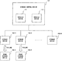
- FIG. 2B shows a configuration example of a storage system in an embodiment.
- the storage system in FIG. 2B comprises a host device 201 and a RAID device 202 .
- the RAID device 202 corresponds to a storage apparatus comprising a controller 211 and four disks of Disk # 0 to Disk # 3 .
- Each disk comprises one or more magnetic disks, and the host device 201 reads/writes data, recognizing each disk as one storage device.
- the number of the disks connected to the controller 211 is not limited to four, and more than four disks are connected to the controller 211 generally.
- the controller 211 comprises a processor 221 , memory 222 and cache memory 223 , and executes a rebuild process in the case of the failures in the Disk # 0 to Disk # 3 .
- the processor 221 executes a program stored in the memory 222 , and thereby executes the rebuild process by using the cache memory 223 as a data buffer.
- counter schemes 1 to 6 shown in FIG. 3 are employed. First, the outlines of respective counter schemes are explained by referring to FIG. 4 to FIG. 8 .
- the controller 211 separately executes the rebuild processes for the first disk and the second disk. Especially, in the rebuild process for the duplicately failing areas corresponding to the failing areas in both disks, the data/parity in the two disks are restored on the data buffer while only the restored data/parity of one disk is written in a disk and the restored data/parity of the other disk is discarded without being written.
- a case where a disk # 0 fails first, and a disk # 1 fails while the data/parity in the disk # 0 is being restored by using a hot spare HS # 0 as shown in FIG. 4 is explained.
- the data/parity in the disk # 0 is restored by the rebuild process for the failure in one disk by using the data/parity in the normally operating disks # 1 to # 3 .
- the data/parity in the rebuilt area in the hot spare HS # 0 is held as it is without being discarded, and only the data/parity remaining non-restored is restored by the rebuild process for the failures in two disks.
- the data/parity remaining non-restored is restored in the hot spare HS # 0 by using the data/parity in the normally operating disks # 2 to # 3 .
- the data/parity in the disk # 1 is created at the same time, however, rebuild process for the disk # 1 is executed separately and independently, therefore, the created data/parity is discarded.
- the entire data/parity is restored by the rebuild process for the failures in two disks by using the data/parity in the normally operating disks # 2 and # 3 parallelly with the rebuild process for the hot spare HS # 0 .
- the data/parity of the disk # 0 created at the same time by the rebuild process for the failures in two disks is discarded.
- the rebuild process for the disk # 0 is switched from the rebuild process for the failure in one disk in which only the disk designated as the restoration target fails into the rebuild process for the failures in two disks in which there is another failing disk in addition to the disk designated as the restoration target, and the data/parity in the restored area is held as it is. Accordingly, the second restoration for the data/parity in the restored area as shown in FIG. 1C is not required so that the restoration of the disk # 0 is completed in a shorter time than the restoration shown in FIG. 1C .
- the controller 211 When the second disk fails, the controller 211 temporarily halts the rebuild process for the first disk, and rebuilds only the second disk until a progress position in the second disk corresponds to that in the first disk. From when the above correspondence is realized, both of the disks are rebuilt simultaneously.
- the disk # 1 fails, initially only the data/parity in the hot spare HS # 1 corresponding to the rebuilt area in the hot spare HS # 0 is restored by the rebuild process for the failure in one disk by using the data/parity in the rebuilt area in the hot spare # 0 and the data/parity in the normally operating disks # 2 and # 3 .
- the restoration of the above data/parity in the hot spare HS # 1 is completed, the remaining data/parity respectively in the host spare HS # 0 and the hot spare HS # 1 are simultaneously restored by the rebuild process for the failures in two disks by using the data/parity in the normally operating disks # 2 and # 3 .
- the merit is obtained that the data/parity in the restored area in the disk # 0 which is currently restored is efficiently utilized for the restoration of the disk # 1 so that the rebuild process for the disk # 1 can be executed more efficiently.
- the controller 211 selects the restoration method by monitoring the progress positions of the rebuild processes for two disks HS # 0 and HS # 1 during the rebuild process. Specifically, the controller 211 checks the difference between the progress positions respectively in the disk HS # 0 and the disk HS # 1 , and when the difference is equal to or greater than the prescribed threshold value, the counter scheme 1 is applied so that the priority is given to the rebuild process for the disk HS # 0 . When the difference is smaller than the above threshold value, the counter scheme 2 is applied so that the rebuild process for the disk HS # 1 is executed until both progress positions correspond to each other. The check of the progress positions is conducted each time the data/parity in the prescribed unit is restored or is conduced each time the data/parity in the prescribed area is restored.
- the difference between the progress positions in the hot spares HS # 0 and HS # 1 corresponds to the waiting time for the start of the restoration for the duplicately failing areas in which the redundancy is lost and the greater the difference of the progress positions is, the more the restoration of the redundancy delays.
- the counter scheme 1 is applied in order to avoid the above too long delay so that the rebuild processes are in parallel executed for the hot spares HS # 0 and HS # 1 .
- a difference from the counter scheme 1 is that the data/parity in the hot spare HS # 1 which is not in the duplicately failing areas in the hot spare HS # 1 is restored by the rebuild process for the failure in one disk by using the data/parity in the rebuilt area in the hot spare HS # 0 and the data/parity in the normally operating disks # 2 and # 3 .
- the rebuild process for the failures in two disks more computation amount is required than that in the rebuild process for the failure in one disk.
- the rebuild process for the failure in one disk executed for the hot spare HS # 1 progresses faster than the foregoing rebuild process for the failures in two disks executed for the hot spare HS # 0 so that the difference of the progress positions is made smaller as time elapses.
- the merit is obtained that the delay of the restoration of the redundancy due to the wait for the start of restoration can be avoided. Also, the efficient utilization of the processor resources and the like can by realized by the parallel processing.
- the controller 211 holds the current progress position of the first disk as the restoration completion position (the stop position which will be described later) when the second disk fails, and executes the rebuild processes simultaneously for both disks from the above positions.
- the rebuild process is executed from the beginning end to the restoration completion position in the second disk and restores the data in non-rebuilt area in the second disk.
- the data/parity in the hot spare HS # 0 and the data/parity in the hot spare HS # 1 which correspond to the non-rebuilt area in the hot spare HS # 0 are simultaneously restored by the rebuild process for the failures in two disks by using the data/parity in the normally operating disks # 2 and # 3 .
- the remaining data/parity in the hot spare HS # 1 is restored by the restoration process for the failure in one disk by using the data/parity in the rebuilt area in the hot spare HS # 0 and the data/parity in the normally operating disks # 2 and # 3 .
- the merit is obtained that the redundancy as the RAID group can be restored in a shorter time by priorly restoring the data/parity in the duplicately failing areas.
- the controller 211 executes the rebuild process from the beginning end to the restoration completion position in the second disk (the process later executed in the counter scheme 4 ) in parallel with the rebuild process for the duplicately failing areas without the wait.
- the process for restoring the data/parity in the duplicately failing areas of the hot spares # 0 and # 1 by the rebuild process for the failures in two disks by using the data/parity in the normally operating disks # 2 and # 3 and the process for restoring the data/parity in the remaining area in the hot spare HS # 1 by the rebuild process for the failure in one disk by using the data/parity in the rebuilt area in the hot spare HS # 0 and the data/parity in the normally operating disks # 2 and # 3 are parallelly executed.
- the controller 211 executes a rebuild process for each prescribed area on the disks by using a bitmap on the cache memory 223 .
- the rebuild order the order of one of the above counter schemes 1 to 5 is employed. From the viewpoint of the preservation of the data/parity it is basically desirable to employ the order of the counter scheme 4 , however, the orders of other counter schemes can be employed for realizing this scheme.
- the rebuild operation when executed as one of processes in the usual read/write access, the fact that the corresponding area is rebuilt is recorded in the bitmap. Accordingly, as the rebuild process, the sequential rebuild processes independent to the read/write access, and the point-to-point rebuild processes as one of the processes in the read/write access are employed at the same time.
- the controller 211 In the point-to-point rebuild process, when the data is restored in response to the read request, the controller 211 writes the restored data in the corresponding position in the disk.
- the controller 211 prepares the bitmap in which one striping corresponds to one bit for example, and manages the progress. If the bitmap is lost, the rebuild process is started from the beginning.
- the bitmap, in which one logical block corresponds to one bit, can be employed too.
- the controller 211 executes one of the operations below.
- the controller 211 can execute the rebuild operations in parallel, and has the functions of back-up/restoration of the bitmap, and turning the power supply on/off.
- the controller 211 is made redundant (duplexity)
- the bitmap is also basically duplexed between the controllers, however, even when the bitmap is not duplexed, the data is not lost. As previously described, when the bitmap is lost, the rebuild process is restarted.
- the controller 211 creates a bitmap for each of the hot spares HS # 0 and HS # 1 , and manages each striping as the data of one bit. For the striping in the non-rebuilt area, “1” is recorded as the corresponding bit, and for the striping in the rebuilt area, “0” is recorded. For all the stripings in the rebuilt area in the hot spare HS # 0 , “0” is each recorded as the corresponding bit at the moment when the disk # 1 fails, and for the other stripings, “0” is each recorded when the corresponding area is rebuilt.
- the merits obtained are ones where the process is effectively executed by writing the data/parity restored by the point-to-point rebuild process back in the disk, and recognizing the above data/parity as the restored data/parity.
- the rebuild process in each counter scheme is triggered by a failure in a disk, or by other rebuild processes.
- the controller 211 designates the triggering disk designated as a treated Main, and adds another failing disk as a treated Sub as occasion demands.
- restoration processes are executed regarding the current positions common between the treated Main and the treated Sub as shown in FIG. 9 .
- the words of “current position” mean the place at which the restoration process is currently executed.
- the controller 211 holds the information regarding all the disks constituting the RAID device 202 as the control information common among all the counter schemes in the cache memory 223 . Specifically, the in formation such as the restoration status (restored, being restored and non-restored), the restoration start position, and the stop position (if needed) is held regarding each disk as shown in FIG. 10 . Regarding the normally operating disk, all the areas are set as restored.
- the restoration start position of the failing disk corresponds to the current position of the restoration process executed for that failing disk designated as the treated Main, and when the restoration process is not executed, the restoration start position is set to the end of the disk (lower end of the disk in FIG. 9 ).
- the restoration process progresses from the restoration start position to the upper direction.
- the stop position means the position at which the restoration process has to stop.
- the restoration status is managed for each area in a unit such as a strip, a logical block and the like.
- the position information such as the current position, the restoration start position, the stop position and the like is managed by using the address of the area in the unit or the identifier of the stripe to which the area in the unit belongs.
- FIG. 11 is a flowchart of a rebuild process.
- the controller 211 initially, sets the end of the treated Main (lower end of the disk in FIG. 9 ) as the current position (step 1101 ), and executes a restoration process by executing the restoration routine (step 1102 ).
- the data/parity designated as the restoration target in the disk designated as the restoration target is created by using the data/parity in other disks, and the restored data/parity is written in the corresponding hot spare.
- the restoration process is executed once, the data/parity in the prescribed unit such as the logical block, the striping and the like is restored.
- the restoration is executed in a unit of striping as the prescribed unit.
- a process after restoration for the rebuild control is executed (step 1103 ).
- the setting of restoration start position, the determination of whether or not the restoration process is to be ended, and the like are conducted. Thereafter, it is checked whether or not the restoration process is determined to be ended in the above process after restoration (step 1104 ).
- the restoration process is not determined to be ended, the process of the step 1102 and the subsequent steps are repeated after progressing the current position just by one stripe (step 1105 ), and when the restoration process is determined to be ended, the rebuild process is ended.
- the rebuild process in FIG. 11 is triggered by a failure in each disk, and the triggering disk is designated as the treated Main. However, another failing disk is not added as the treated Sub. Therefore, after the failure in the second disk, two rebuild processes are executed in parallel, and only the treated Main is the disk designated as the restoration target in each rebuild process.
- FIG. 12 is a flowchart of a restoration routine of the counter scheme 1 .
- the controller 211 initially, sets the treated Main as the restoration target disk, sets the current position in the disk (step 1201 ), and checks the number of the failing disks (step 1202 ). When the number of the failing disks is one, it is determined to employ the rebuild process for the failure in one disk as the restoration method (step 1203 ).
- the data/parity which is needed for the rebuild process for the failure in one disk is read from the normally operating disks (step 1205 ) and it is checked whether or not all of the above needed data/parity is read (step 1206 ).
- the data/parity in the restoration target disk belonging to the same stripe is restored by using the read data/parity, and the restored data/parity is written in the corresponding hot spare (step 1207 ).
- step 1206 In the case where a read error occurs in the step 1206 , it is recognized that the disk designated as the read target fails. Then, the number of the failing disks is checked (step 1208 ), and when the above number is two, the processes of the step 1202 and the subsequent steps are executed.
- the restoration method is switched into the rebuild process for the failures in two disks (step 1204 ), and the data/parity which is needed for the rebuild process for the failures in two disks is read from the normally operating disks (step 1205 ).
- the data/parity in the restoration target disk is restored by using the read data/parity, and the restored data/parity is written in the corresponding hot spare (step 1207 ).
- the error process is executed (step 1209 ).
- FIG. 13 is a flowchart of the process after restoration in the counter scheme 1 .
- the controller 211 initially, sets the current position used in the restoration routine to the restoration start position in the treated Main (step 1301 ), and checks whether or not the restoration for the entire area in the treated Main is completed (step 1302 ). In this example, when the current position used in the restoration routine has reached the end of the treated Main (upper end of the disk in FIG. 9 ), it is determined that the restoration for the entire area is completed. When the restoration for the entire area is not completed, it is determined that the restoration process has to be continued (step 1303 ), and when the restoration for the entire area is completed, it is determined that the restoration process is to be ended (step 1304 ).
- the rebuild process is triggered for the disk # 0 designated as the treated Main as shown in FIG. 4 .
- the number of the failing disks is one (step 1202 in FIG. 12 ), so that the rebuild process for the failure in one disk is employed (step 1203 ).
- the data/parity which is needed for restoring the data/parity in the disk # 0 by the rebuild process for the failure in one disk is read (step 1205 ).
- the data/parity in the disk # 0 is restored by using the read data/parity and the restored data/parity is written in the hot spare HS # 0 (step 1207 ).
- the current position in the disk # 0 is set as the restoration start position in the disk # 0 (step 1301 in FIG. 13 ), and it is determined that the restoration process is to be continued (step 1303 ).
- the restoration start position is referred to by other processes such as the read/write access and the like to the disk # 0 .
- the restoration routine and the process after restoration as above are repeatedly executed for each one striping (step 1105 in FIG. 11 ).
- the number of the failing disks becomes two (step 1202 ) so that the restoration method is switched into the rebuild process for the failures in two disks (step 1204 ), and the data/parity which is needed for restoring the data/parity in the disks # 0 and # 1 by the rebuild process for the failures in two disks is read from the normally operating disks # 2 and # 3 (step 1205 ). Then, the data/parity in the disks # 0 and # 1 is restored by using the read data/parity, and the data/parity in the disk # 0 among the restored data/parity is written in the hot spare # 0 (step 1207 ).
- the process after restoration which is the same as that before the failure in the disk # 1 is executed.
- the restoration routine and the process after restoration as above are repeatedly executed for each one striping (step 1105 ), and when the restoration for the entire area in the disk # 0 is completed (step 1304 ), it is determined that the rebuild process for the disk # 0 is to be ended (step 1104 ).
- the disk # 1 fails, another rebuild process is triggered for the disk # 1 designated as the treated Sub.
- the number of the failing disks is two (step 1202 ) so that the rebuild process for the failures in two disks is employed (step 1204 ), and the data/parity which is needed for restoring the data/parity in the disks # 0 and # 1 by the rebuild process for the failures in two disks is read from the normally operating disks # 2 and # 3 (step 1205 ).
- the data/parity in the disks # 0 and # 1 is restored by using the read data/parity, and the data/parity in the disk # 1 among the restored data/parity is written in the hot spare # 1 (step 1207 ).
- the process after restoration which is the same as that before the failure in the disk # 0 is executed.
- the restoration routine and the process after restoration as above are repeatedly executed for each one striping (step 1105 ), and when the restoration for the entire area in disk # 0 is completed (step 1304 ), it is determined that the rebuild process for the disk # 1 is to be ended (step 1104 ).
- the rebuild process in FIG. 11 is triggered by a failure in each disk, and the triggering disk is designated as the treated Main.
- the second disk fails the rebuild process for the first failing disk designated as the treated Main is suspended, and the rebuild process for the second failing disk designated as the treated Main starts.
- the current position in the second failing disk reaches the progress position which is the same as that in the first failing disk, the first failing disk is added as the treated Sub.
- FIG. 14 is a flowchart of a restoration routine of the counter scheme 2 .
- the restoration target disk is expressed by the treated Main and the treated Sub, and at most two disks can be set as the restoration target disks.
- the restoration method is selected in accordance with the number of the restoration target disks, instead of failing disks.
- the controller 211 initially, sets the treated Main/the treated Sub designated as the restoration target disks, sets the current position in the treated Main (step 1401 ). When the treated Sub is not set, only the treated Main is set as the restoration target disk.
- the controller 211 checks the number of the restoration target disks (step 1402 ). When the number of the restoration target disk is one, it is determined to employ the rebuild process for the failure in one disk designated as the restoration method (step 1403 ). And the data/parity which is needed for the rebuild process for the failure in one disk among the data/parity belonging to the stripe of the current position is read from the normally operating disks (step 1405 ), and it is checked whether or not all the above needed data/parity is read (step 1406 ). When all the above data/parity is read, the data/parity in the restoration target disks belonging to the same stripe is restored by using the read data/parity, and the restored data/parity is written in the corresponding hot spare (step 1407 ).
- step 1406 In the case where a read error occurs in the step 1406 , it is recognized that the disk designated as the read target fails. Then, the number of the failing disks is checked (step 1408 ), and when the above number is one, the failing disk is added as the restoration target disk (step 1410 ) and the processes of the step 1402 and the subsequent steps are executed.
- the restoration method is switched into the rebuild process for the failures in two disks (step 1404 ), and the data/parity which is needed for the rebuild process for the failures in two disks is read from the normally operating disks (step 1405 ).
- the data/parity in the restoration target disks is restored by using the read data/parity, and the restored data/parity is respectively written in the corresponding hot spares (step 1407 ).
- the error process is executed (step 1409 ).
- FIG. 15 is a flowchart of the process after restoration in the counter scheme 2 .
- the controller 211 initially, sets the current position in the treated Main at the time when the restoration routine is ended as the restoration start positions in the treated Main/the treated Sub (step 1501 ), and checks whether or not the following condition a is satisfied (step 1502 ).
- Condition a There is another failing disk in addition to the treated Main, the stop position is set neither in the treated Main nor in another failing disk, and the restoration start position in another failing disk is behind (lower than) that in the treated Main.
- the restoration start position in the above other failing disk is behind that in the treated Main means that the restoration process in the other failing disk is executed with a delay to that in the treated Main.
- the restoration start position in the treated Main is set as the stop position in another failing disk (step 1506 ), and it is determined that the restoration process is to be ended in order to suspend the rebuild process for the treated Main (step 1508 ).
- step 1503 it is checked whether or not the restoration for the entire area in the treated Main is completed.
- step 1508 it is determined that the restoration process is to be ended.
- step 1504 When the restoration for the entire area is not completed, it is checked whether or not the stop position is set in the treated Main, and at the same time, the current position in the treated Main corresponds to the above stop position (step 1504 ). When the current position corresponds to the stop position, another failing disk is added as the treated Sub (step 1507 ) and it is determined that the restoration process is to be continued (step 1505 ).
- step 1505 it is determined that the restoration process is to be continued as it is (step 1505 ).
- the rebuild process for the disk # 0 as the treated Main is triggered.
- the rebuild process for the failure in one disk is employed (step 1403 in FIG. 14 ) because the number of the restoration target disks is one (step 1401 in FIG. 14 ), and the data/parity which is needed for restoring the data/parity in the disk # 0 by the rebuild process for the failure in one disk is read from the normally operating disks # 1 to # 3 (step 1405 ).
- the data/parity in the disk # 0 is restored by using the read data/parity, and the restored data/parity is written in the hot spare HS # 0 (step 1407 ).
- the current position in the disk # 0 is set as the restoration start position in the disk # 0 (step 1501 in FIG. 15 ), and it is determined that the restoration process is to be continued (step 1505 ) because there is not another failing disk (step 1502 ).
- the restoration routine and the process after restoration as above are repeatedly executed for each one striping (step 1105 in FIG. 11 ).
- step 1502 when the disk # 1 fails, the condition a is satisfied (step 1502 ) because the restoration start position in the disk # 0 designated as the treated Main corresponds to the current position in the disk # 0 (step 1501 ), and the restoration start position in the disk # 1 as another failing disk corresponds to the lower end of the disk # 1 . Then, the restoration start position in the disk # 0 is set to the stop position in the disk # 1 (step 1506 ), and it is determined that the restoration process is to be ended (step 1508 ). Thereby, the rebuild process for the disk # 0 designated as the treated Main is suspended (step 1104 ).
- step 1403 The rebuild process for the failure in one disk is employed (step 1403 ) because the number of the restoration target disks is one (step 1401 ), and the data/parity which is needed for restoring the data/parity in the disk # 1 by the rebuild process for the failure in one disk is read from the normally operating disks # 0 , # 2 and # 3 (step 1405 ). However, as for the disk # 0 , only restored data/parity which has been written in the hot spare HS # 0 is read.
- the data/parity in the disk # 1 is restored by using the read data/parity and the restored data/parity is written in the hot spare HS # 1 (step 1407 ).
- the current position in the disk # 1 is set as the restoration start point in the disk # 1 (step 1501 ), and the condition a is not satisfied (step 1502 ) because the stop position is already set in the disk # 1 . Further, because the current position in the disk # 1 has not reached the stop position in the disk # 1 (step 1504 ), it is determined that the restoration process is to be continued (step 1505 ).
- the restoration routine and the process after restoration as above are repeatedly executed for each one striping (step 1105 ).
- the current position in the disk # 1 reaches the stop position in the disk # 1 (step 1504 )
- the disk # 0 for which the restoration process is suspended is added as the treated Sub (step 1507 ), and it is determined that the restoration process is to be continued (step 1505 ). Thereby, the current position is updated (step 1105 ).
- the number of the restoration target disks becomes two (step 1404 ), the restoration method is switched into the rebuild process for the failures in two disks (step 1404 ), and the data/parity which is needed for restoring the data/parity in the disks # 0 and # 1 by the rebuild process for the failures in two disks is read from the normally operating disks # 2 and # 3 (step 1405 ). And the data/parity in the disks # 0 and # 1 is restored by using the read data/parity, and the restored data/parity is respectively written in the hot spares HS # 0 and HS # 1 (step 1407 ).
- the current position in the disk # 1 is set as the restoration start positions in the disks # 0 and # 1 (step 1501 ), and because the current position in the disk # 1 has exceeded the stop position in the disk # 1 (step 1504 ), it is determined that the restoration process is to be continued (step 1505 ).
- the restoration routine and the process after restoration as above are repeatedly executed for each one striping (step 1105 ).
- the restoration for the entire area in the disk # 1 is completed (step 1508 )
- the rebuild process for the disk # 1 designated as the treated Main is ended (step 1104 ). Also, because the current position in the disk # 0 as the treated Sub has reached the upper end of the disk # 0 at the above moment, also the restoration for the disk # 0 is ended together.
- the rebuild process in FIG. 11 is triggered by a failure in each disk, and the triggering disk is designated as the treated Main.
- the counter scheme 1 or the counter scheme 2 is selected in accordance with the difference between the progress positions respectively in the two failing disks.
- the counter scheme 1 When the difference between the progress positions is equal to or greater than the threshold value, the counter scheme 1 is selected so that two rebuild processes are parallelly executed. However, in this scheme, a difference from the counter scheme 1 is that the data/parity in the second failing disk is restored by the rebuild process for the failure in one disk by using the data/parity in the rebuilt area in the first failing disk and the data/parity in the normally operating disks.
- the counter scheme 2 is selected so that the rebuild process for the first failing disk designated as the treated Main is suspended, and the rebuild process for the second failing disk designated as the treated Main starts. And when the current position in the second failing disk reaches the same progress position that is the same with that in the first failing disk, the first failing disk is added as the treated Sub.
- the flowchart of the restoration routine in the counter scheme 3 is similar to that in the counter scheme 2 , and the flowchart of the process after restoration is shown in FIG. 16 .
- the process after restoration in FIG. 16 employs the configuration including the determination step of step 1603 in addition to the process after restoration in FIG. 15 .
- the controller 211 compares, with the threshold value, the difference between the restoration start positions respectively in another failing disk and the treated Main.
- the restoration start position in the treated Main is set to the stop position in another failing disk (step 1607 ), and it is determined that the restoration process is to be ended (step 1609 ).
- the processes of the step 1604 and the subsequent steps are executed.
- the stop position is set in another failing disk (step 1607 ). In the cases other than the above, the stop position is not set.
- the rebuild process for the disk # 0 designated as the treated Main is triggered, and the process similar to that in the counter scheme 2 is executed until the disk # 1 fails.
- step 1602 in FIG. 16 the condition a is satisfied (step 1602 in FIG. 16 ) so that the difference between the restoration positions respectively in the disk # 0 and the disk # 1 is compared with the threshold value (step 1603 ).
- the threshold value Upon this, if a sufficient period of time has elapsed since the failure of the disk # 0 , it is thought that the restoration process for the disk # 0 has much progressed so that the difference between the restoration start positions has exceeded the threshold value.
- the processes of step 1604 and the subsequent steps are executed, and because the stop position is not set in the disk # 0 (step 1605 ), it is determined that the restoration process is to be continued (step 1606 ).
- step 1401 in FIG. 14 the rebuild process for the failure in one disk is employed (step 1403 ), and the data/parity which is needed for restoring the data/parity in the disk # 0 by the rebuild process for the failure in one disk is read from the normally operating disks # 1 to # 3 (step 1405 ).
- the read error occurs and the disk # 1 is added as the restoration target disk (step 1410 ) so that the number of the restoration target disks becomes two.
- the restoration method is switched into the rebuild process for the failures in two disks (step 1404 ), and the data/parity which is needed for restoring the data/parity in the disks # 0 and # 1 by the rebuild process for the failures in two disks is read from the normally operating disks # 2 and # 3 (step 1405 ). And the data/parity in the disks # 0 and # 1 is restored by using the read data/parity, and the restored data/parity in the disk # 0 among the above restored data/parity is written in the hot spare HS # 0 (step 1407 ).
- the current position in the disk # 0 is set as the restoration start position in the disk # 0 (step 1601 ), and the condition a is satisfied (step 1602 ), however, the difference between the restoration start positions is still greater than the threshold value (step 1603 ). Also, because the stop position is not set in the disk # 0 (step 1605 ), it is determined that the restoration process is to be continued (step 1606 ).
- the restoration routine and the process after restoration as above are repeatedly executed for each one striping (step 1105 in FIG. 11 ).
- the disk # 1 fails, another rebuild process is triggered for the disk # 1 designated as the treated Main. Because the number of the restoration target disks is one (step 1401 ), the rebuild process for the failure in one disk is employed (step 1403 ), and the data/parity which is needed for restoring the data/parity in the disk # 1 by the rebuild process for the failure in one disk is read from the normally operating disks # 0 , # 2 and # 3 (step 1405 ). However, regarding the disk # 0 , the restored data/parity which has been written in the hot spare HS # 0 is read.
- the data/parity in the disk # 1 is restored by using the read data/parity, and the restored data/parity is written in the hot spare HS # 1 (step 1407 ).
- the current position in the disk # 1 is set as the restoration start position in the disk # 1 (step 1601 ), and because the restoration start position in the disk # 0 designated as another failing disk has exceeded the restoration start position in the disk # 1 designated as the treated Main, the condition a is not satisfied (step 1602 ). Also, because the stop position is not set in the disk # 1 (step 1605 ), it is determined that the restoration process is to be continued (step 1606 ). The restoration routine and the process after restoration as above are repeatedly executed for each one striping (step 1105 ).
- the rebuild process for the failures in two disks for the disk # 0 designated as the treated Main and the rebuild process for the failure in one disk for the disk # 1 designated as the treated Main are executed in parallel so that the restoration start position in the disk # 1 gradually approaches the restoration start position in the disk # 0 .
- the restoration start position in the disk # 0 is set to the stop position in the disk # 1 (step 1607 ), and it is determined that the restoration process is to be ended (step 1609 ). Thereby, the rebuild process for the disk # 0 designated as the treated Main is suspended (step 1104 ).
- step 1602 the condition a is not satisfied because the stop position is already set in the disk # 1 (step 1602 ). Also, because the current position in the disk # 1 has not reached the stop position in the disk # 1 (step 1605 ), it is determined that the restoration process is to be continued (step 1606 ).
- the current position in the disk # 1 reaches the stop position in the disk # 1 (step 1605 )
- the disk # 0 for which the restoration process is suspended is added as the treated Sub (step 1608 ), and it is determined that the restoration process is to be continued (step 1606 ).
- the current position is updated (step 1105 ).
- the number of the restoration target disks becomes two (step 1401 ) so that the rebuild process for the failures in two disks is employed (step 1404 ), and the data/parity which is needed for restoring the data/parity in the disk # 0 and the disk # 1 by the rebuild process for the failures in two disks is read from the normally operating disks # 2 and # 3 (step 1405 ). And the data/parity in the disks # 0 and # 1 is restored by using the read data/parity, and the restored data/parity is respectively written in the hot spares HS # 0 and HS # 1 (step 1407 ).
- the current position in the disk # 1 is set as the restoration start positions in the disks # 0 and # 1 (step 1601 ) and the current position in the disk # 1 has exceeded the stop position in the disk # 1 (step 1605 ), accordingly, it is determined that the restoration process is to be continued (step 1606 ).
- the restoration routine and the process after restoration as above are repeatedly executed for each one striping (step 1105 ). And when the restoration for the entire area in the disk # 1 is completed (step 1609 ), the rebuild process for the disk # 1 designated as the treated Main is ended (step 1104 ). Also, because the current position in the disk # 0 designated as the treated Sub has reached the upper end of the disk # 0 at the above moment, also the restoration for the disk # 0 is ended together.
- the rebuild process in FIG. 11 is triggered by a failure in a disk, or by other rebuild processes.
- the triggering disk is designated as the treated Main.
- the former trigger only one rebuild process is triggered for each one RAID group. Accordingly, even when the second disk fails, another rebuild process is not triggered if the rebuild process for a RAID group has already been triggered.
- the current position in the first failing disk is set as the stop position in the second failing disk, the second failing disk is added as the treated Sub, and the rebuild process is continued.
- the rebuild process for the first failing disk is completed, the rebuild process for the second failing disk designated as the treated Main is executed from the lower end to the stop position in the second failing disk.
- the flowchart of the restoration routine in the counter scheme 4 is similar to that in the counter scheme 2 .
- FIG. 17 is a flowchart of the process after restoration in the counter scheme 4 .
- the controller 211 initially, sets the current position in the treated Main at the moment when the restoration routine is ended to the restoration start positions in the treated Main/the treated Sub (step 1701 ), and checks whether or not the following condition b is satisfied (step 1702 ).
- Condition b There is another failing disk in addition to the treated Main, and the stop position is set neither in the treated Main nor in another failing disk.
- the restoration start position in the treated Main is set to the stop position in another failing disk, and another failing disk is added as the treated Sub (step 1706 ). Then, it is checked whether or not the restoration for the entire area in the treated Main is completed (step 1703 ). When the condition b is not satisfied, the process in the step 1703 is executed as it is.
- step 1704 When the restoration for the entire area is not completed, it is checked whether or not the stop position in the treated Main corresponds to the stop position in the treated Main (step 1704 ). When the current position corresponds to the stop position, it is determined that the restoration process is to be ended (step 1708 ).
- step 1705 it is determined that the restoration process is to be continued as it is (step 1705 ).
- the rebuild process for the disk # 0 designated as the treated Main is triggered.
- the rebuild process for the rebuild process for the failure in one disk is employed (step 1403 ) because the number of the restoration target disks is one (step 1401 in FIG. 14 ), and the data/parity which is needed for restoring the data/parity in the disk # 0 by the rebuild process for the failure in one disk is read from the normally operating disks # 1 to # 3 (step 1405 ).
- the data/parity in the disk # 0 is restored by using the read data/parity, and the restored data/parity is written in the hot spare HS # 0 (step 1407 ).
- the current position in the disk # 0 is set as the restoration start position in the disk # 0 (step 1701 in FIG. 17 ), and it is determined that the restoration process is to be continued (step 1705 ) because there is not another failing disk (step 1702 ).
- the restoration routine and the process after restoration as above are repeatedly executed for each one striping (step 1105 in FIG. 11 ).
- step 1702 when the disk # 1 fails, the condition b is satisfied (step 1702 ), the restoration start position in the disk # 0 is set to the stop position in the disk # 1 , and the disk # 1 is added as the treated Sub (step 1706 ). However, because the stop position is not set in the disk # 0 (step 1704 ), it is determined that the rebuild process is to be continued (step 1705 ).
- the number of the restoration target disks becomes two (step 1401 ), so that the restoration method is switched into the rebuild process for the failures in two disks (step 1404 ), and the data/parity which is needed for restoring the data/parity in the disks # 0 and # 1 by the rebuild process for the failures in two disks is read from the normally operating disks # 2 and # 3 (step 1405 ). And the data/parity in the disks # 0 and # 1 is restored by using the read data/parity, and the restored data/parity is respectively written in the hot spares HS # 0 and HS # 1 (step 1407 ).
- the current position in the disk # 0 is set as the restoration start points in the disk # 0 and the disk # 1 (step 1701 ), and the condition b is not satisfied (step 1702 ) because the stop position is already set in the disk # 1 . Further, because the stop position is not set in the disk # 0 (step 1704 ), it is determined that the rebuild process is to be continued (step 1705 ).
- the restoration routine and the process after restoration as above are repeatedly executed for each one striping (step 1105 ). And when the restoration for the entire area in the disk # 0 is completed (step 1703 ), another rebuild process for the disk # 1 designated as the treated Main is triggered (step 1707 ), and it is determined that the restoration process is to be ended (step 1708 ). Thereby, the rebuild process for the disk # 0 designated as the treated Main is ended (step 1104 ). At the above moment, the current position in the disk # 1 designated as the treated Sub has reached the upper end of the disk # 1 .
- the lower end in the disk # 1 is set as the current position (step 1101 ).
- the rebuild process for the rebuild process for the failure in one disk is employed (step 1403 ) because the number of the restoration target disks is one (step 1401 ), and the data/parity which is needed for restoring the data/parity in the disk # 1 by the rebuild process for the failure in one disk is read from the normally operating disks # 0 , # 2 and # 3 (step 1405 ).
- the restored data/parity which has been written in the hot spare HS # 0 is read.
- the data/parity in the disk # 1 is restored by using the read data/parity, and the restored data/parity is written in the hot spare HS # 1 (step 1407 ).
- the current position in the disk # 1 is set as the restoration start position in the disk # 1 (step 1701 ), and the stop position is already set in the disk # 1 , accordingly, the condition b is not satisfied (step 1702 ) Also, because the current position in the disk # 1 has not reached the stop position in the disk # 1 (step 1704 ), it is determined that the restoration process is to be continued (step 1705 ).
- the restoration routine and the process after restoration as above are repeatedly executed for each one striping (step 1105 ), and the current position in the disk # 1 reaches the stop position. At this moment, the current position in the disk # 1 has not reached the upper end of the disk # 1 so that it is determined that the restoration for the entire area is not completed (step 1703 ). However, the current position corresponds to the stop position (step 1704 ), it is determined that the restoration process is to be ended (step 1708 ). Thereby, the rebuild process for the disk # 1 designated as the treated Main is ended (step 1104 ), and the restoration for the disk # 1 is completed.
- the rebuild process in FIG. 11 is triggered by a failure in each disk, and the triggering disk is designated as the treated Main.
- the current position in the first failing disk is set as the stop position in the second failing disk, the second failing disk is added as the treated Sub, and the rebuild process is continued. And at the same time, the rebuild process for the second failing disk designated as the treated Main is triggered to be executed in parallel with the rebuild process for the first failing disk designated as the treated Main.
- the flowchart of the restoration routine in the counter scheme 5 is similar to that in the counter scheme 2 , and the flowchart of the flowchart of the process after restoration is shown in FIG. 18 .
- the process after restoration in FIG. 18 employs the configuration excluding the process of step 1707 from the process after restoration in FIG. 17 .
- the rebuild process for the disk # 0 designated as the treated Main is triggered, and the process similar to that in the counter scheme 4 is executed until the disk # 1 fails.
- step 1802 when the disk # 1 fails, the condition b is satisfied (step 1802 ), the restoration start position in the disk # 0 is set to the stop position in the disk # 1 , and the disk # 1 is added as the treated Sub (step 1806 ). However, because the stop position is not set in the disk # 0 (step 1804 ), it is determined that the restoration process is to be continued (step 1805 ).
- the number of the restoration target disks becomes two (step 1401 ), so that the restoration method is switched into the rebuild process for the failures in two disks (step 1404 ), and the data/parity which is needed for restoring the data/parity in the disks # 0 and # 1 by the rebuild process for the failures in two disks is read from the normally operating disks # 2 and # 3 (step 1405 ). And the data/parity in the disks # 0 and # 1 is restored by using the read data/parity, and the restored data/parity is respectively written in the hot spares HS # 0 and HS # 1 (step 1407 ).
- the current position in the disk # 0 is set as the restoration start positions in the disk # 0 and the disk # 1 (step 1801 ), and the stop position is already set in the disk # 1 , accordingly, the condition b is not satisfied (step 1802 ). Also, because the stop position is not set in the disk # 0 (step 1804 ), it is determined that the restoration process is to be continued (step 1805 ).
- the restoration routine and the process after restoration as above are repeatedly executed for each one striping (step 1105 ), and when the restoration for the entire area in the disk # 0 is completed (step 1803 ), it is determined that the restoration process is to be ended (step 1807 ). Thereby, the rebuild process for the disk # 0 designated as the treated Main is ended (step 1104 ). At the above moment, the current position in the disk # 1 designated as the treated Sub has reached the upper end of the disk # 1 .
- step 1101 when the disk # 1 fails, another rebuild process for the disk # 1 designated as the treated Main is triggered, and the lower end of the disk # 1 is set as the current position (step 1101 ).
- the rebuild process for the rebuild process for the failure in one disk is employed (step 1403 ) because the number of the restoration target disks is one (step 1401 ), and the data/parity which is needed for restoring the data/parity in the disk # 1 by the rebuild process for the failure in one disk is read from the normally operating disks # 0 , # 2 and # 3 (step 1405 ). However, as for the disk # 0 , only restored data/parity which has been written in the hot spare HS # 0 is read.
- the data/parity in the disk # 1 is restored by using the read data/parity, and the restored data/parity is written in the hot spare HS# 1 (step 1407 ).
- the current position in the disk # 1 is set as the restoration start position in the disk # 1 (step 1801 ), and the stop position is already set in the disk # 1 , accordingly, the condition b is not satisfied (step 1802 ). Also, because the current position in the disk # 1 has not reached the stop position in the disk # 1 (step 1804 ), it is determined that the restoration process is to be continued (step 1805 ).
- the restoration routine and the process after restoration as above are repeatedly executed for each one striping (step 1105 ), and the current position in the disk # 1 reaches the stop position. At this moment, the current position in the disk # 1 has not reached the upper end of the disk # 1 so that it is determined that the restoration for the entire area is not completed (step 1803 ). However, the current position corresponds to the stop position (step 1804 ), it is determined that the restoration process is to be ended (step 1807 ). Thereby, the rebuild process for the disk # 1 designated as the treated Main is ended (step 1104 ).
- the rebuild process for the failures in two disks for the disk # 0 designated as the treated Main and the rebuild process for the failure in one disk for the disk # 1 designated as the treated Main are executed in parallel, and when both of the above processes are ended, the restoration for the disk # 1 is completed.
- a bitmap for indicating the restoration status for each prescribed area such as a strip, a logical block or the like in each disk is added as control information.
- the control of the progress for all the disks is conducted by one of the counter schemes 1 to 5 .
- the controller 211 refers to the bit information corresponding to the restoration position in the bitmap. Then, as shown in FIG. 19 , when there is an area which has already been restored as one of the processes in the read/write access or the like, the restoration for the restored area is skipped. Thereby, the unnecessary cost for the restoration process is reduced.
- FIG. 20 shows a method of providing program and data to be used for the process by the processor 221 in the controller 211 .
- the program and the data stored in an external device 1801 or a transportable storage medium 1802 such as an information processing device or the like is loaded to the memory 222 in the RAID device 202 .
- the external device 1801 generates carrier signals for carrying the program and the data, and transmits the program and the data to the RAID device 202 via an arbitrary transmission medium on a communications network.
- the transportable storage medium 1802 is an arbitrary computer readable storage medium such as a memory card, a flexible disk, an optical disk, a magneto optical disk or the like.
- the processor 221 executes the program by using the data in the storage medium, and executes required processes.
- FIG. 21 and FIG. 22 respectively show other configuration examples of the storage system.
- FIG. 21 shows an example in which a host bus adapter provided in the host device executes a rebuild process.
- FIG. 22 shows an example in which software provided in the host device executes a rebuild process. In both configurations, the necessary program and data are provided in the same manner as in the case of the RAID device 202 .
- the storage system in FIG. 21 comprises a host device 1901 and Disks # 0 to # 3 .
- the host device 1901 comprises a host bus adapter 1911 .
- the host bus adapter 1911 comprises a processor 1921 , memory 1922 and cache memory 1923 , and executes a rebuild process for the case where the Disks # 0 to # 3 fail.
- the processor 1921 executes a program stored in the memory 1922 and thereby, executes the above described rebuild process.
- the storage system in FIG. 22 comprises a host device 2001 and Disks # 0 to # 3 .
- the host device 2001 comprises a processor 2011 , memories 2012 and 2013 , and executes a rebuild process for the case where the Disks # 0 to # 3 fail.
- the processor 2011 executes a program stored in the memory 2012 and thereby, executes the above described rebuild process on the memory 2013 .
- a magnetic disk device is employed as a disk device, however, the present intention can be applied also to a storage system using other disk devices such as an optical disk device, a magneto optical disk device or the like, or other storage devices such as a tape device.
Applications Claiming Priority (2)
| Application Number | Priority Date | Filing Date | Title |
|---|---|---|---|
| JP2005073669A JP4754852B2 (ja) | 2005-03-15 | 2005-03-15 | ストレージ制御装置および方法 |
| JP2005-073669 | 2005-03-15 |
Publications (2)
| Publication Number | Publication Date |
|---|---|
| US20060212748A1 US20060212748A1 (en) | 2006-09-21 |
| US7809979B2 true US7809979B2 (en) | 2010-10-05 |
Family
ID=36648659
Family Applications (1)
| Application Number | Title | Priority Date | Filing Date |
|---|---|---|---|
| US11/237,657 Expired - Fee Related US7809979B2 (en) | 2005-03-15 | 2005-09-29 | Storage control apparatus and method |
Country Status (5)
| Country | Link |
|---|---|
| US (1) | US7809979B2 (ja) |
| EP (1) | EP1703397A3 (ja) |
| JP (1) | JP4754852B2 (ja) |
| KR (1) | KR100701563B1 (ja) |
| CN (1) | CN100392611C (ja) |
Cited By (6)
| Publication number | Priority date | Publication date | Assignee | Title |
|---|---|---|---|---|
| US20090313498A1 (en) * | 2008-06-13 | 2009-12-17 | Fujitsu Limited | Control method and storage device |
| US20100174940A1 (en) * | 2009-01-07 | 2010-07-08 | Canon Kabushiki Kaisha | Information processing apparatus, method for controlling the information processing apparatus, and storage medium |
| US20130238928A1 (en) * | 2012-03-08 | 2013-09-12 | Kabushiki Kaisha Toshiba | Video server and rebuild processing control method |
| US20190220376A1 (en) * | 2018-01-18 | 2019-07-18 | EMC IP Holding Company LLC | Method and device for managing storage system |
| US10503598B2 (en) * | 2013-07-01 | 2019-12-10 | Pure Storage, Inc. | Rebuilding data while reading data in a dispersed storage network |
| US11182075B1 (en) * | 2010-10-11 | 2021-11-23 | Open Invention Network Llc | Storage system having cross node data redundancy and method and computer readable medium for same |
Families Citing this family (30)
| Publication number | Priority date | Publication date | Assignee | Title |
|---|---|---|---|---|
| JP4303187B2 (ja) * | 2004-11-10 | 2009-07-29 | 富士通株式会社 | プログラム、記憶制御方法及び記憶装置 |
| TWI295021B (en) * | 2004-12-10 | 2008-03-21 | Infortrend Technology Inc | Storage system and method for handling bad storage device data therefor |
| JP2008046986A (ja) * | 2006-08-18 | 2008-02-28 | Hitachi Ltd | ストレージシステム |
| JP4499776B2 (ja) * | 2007-10-31 | 2010-07-07 | 富士通株式会社 | ストレージ制御装置、方法、及びプログラム |
| US7877626B2 (en) * | 2007-12-31 | 2011-01-25 | Datadirect Networks, Inc. | Method and system for disk storage devices rebuild in a data storage system |
| US7979635B2 (en) * | 2008-02-14 | 2011-07-12 | International Business Machines Corporation | Apparatus and method to allocate resources in a data storage library |
| JP2010049637A (ja) * | 2008-08-25 | 2010-03-04 | Hitachi Ltd | 計算機システム、ストレージシステム及び構成管理方法 |
| JP5107196B2 (ja) * | 2008-09-18 | 2012-12-26 | 株式会社東芝 | 情報処理装置および再構築処理および修復処理の制御方法 |
| CN101482733B (zh) * | 2009-02-04 | 2011-10-19 | 浙江中控技术股份有限公司 | 一种数据冗余的方法及装置 |
| JP5218147B2 (ja) * | 2009-02-26 | 2013-06-26 | 富士通株式会社 | ストレージ制御装置,ストレージ制御方法およびストレージ制御プログラム |
| JP5391993B2 (ja) * | 2009-10-19 | 2014-01-15 | 富士通株式会社 | ディスクアレイ装置 |
| US8341457B2 (en) * | 2010-03-11 | 2012-12-25 | Lsi Corporation | System and method for optimizing redundancy restoration in distributed data layout environments |
| US8726070B2 (en) * | 2010-09-27 | 2014-05-13 | Dell Products L.P. | System and method for information handling system redundant storage rebuild |
| CN102055797A (zh) * | 2010-11-29 | 2011-05-11 | 北京卓微天成科技咨询有限公司 | 一种云存储的数据存取的方法、装置及系统 |
| CN102164165B (zh) * | 2011-02-18 | 2013-06-12 | 杭州宏杉科技有限公司 | 一种网络存储系统的管理方法及装置 |
| JP5729043B2 (ja) * | 2011-03-17 | 2015-06-03 | 富士通株式会社 | ストレージ装置および制御装置 |
| JP5891890B2 (ja) * | 2012-03-26 | 2016-03-23 | 富士通株式会社 | ストレージシステム、ストレージ装置およびデータ復元方法 |
| CN102681794B (zh) * | 2012-04-23 | 2014-12-10 | 浪潮(北京)电子信息产业有限公司 | 基于双控制器实现磁盘冗余阵列保护的方法及系统 |
| CN102684782A (zh) * | 2012-05-08 | 2012-09-19 | 成都瑞凌科信息技术有限公司 | Epon系统的保护装置和数据冗余备份方法及监控方法 |
| WO2014016860A1 (en) * | 2012-07-23 | 2014-01-30 | Hitachi, Ltd. | Raid storage system and rebuild process |
| CN103902232B (zh) * | 2012-12-28 | 2018-11-09 | 联想(北京)有限公司 | 一种写入的数据的方法及装置 |
| CN103970481B (zh) * | 2013-01-29 | 2017-03-01 | 国际商业机器公司 | 重建存储器阵列的方法和装置 |
| JP6171616B2 (ja) * | 2013-06-24 | 2017-08-02 | 富士通株式会社 | ストレージ制御装置、及びストレージ制御プログラム |
| JP2015210658A (ja) | 2014-04-25 | 2015-11-24 | 富士通株式会社 | 記憶制御装置、データ復旧プログラム、およびデータ復旧方法 |
| CN106227627A (zh) * | 2016-08-22 | 2016-12-14 | 浪潮(北京)电子信息产业有限公司 | 一种raid在数据恢复后再插入新磁盘的数据分布方法及系统 |
| CN113407122B (zh) * | 2016-12-21 | 2023-08-25 | 伊姆西Ip控股有限责任公司 | Raid重建的方法和设备 |
| US10437691B1 (en) * | 2017-03-29 | 2019-10-08 | Veritas Technologies Llc | Systems and methods for caching in an erasure-coded system |
| CN110058965B (zh) * | 2018-01-18 | 2023-07-28 | 伊姆西Ip控股有限责任公司 | 存储系统中的数据重建方法及设备 |
| CN111381997B (zh) * | 2018-12-28 | 2024-03-01 | 杭州宏杉科技股份有限公司 | 一种raid重建方法及装置 |
| CN110389724B (zh) * | 2019-07-23 | 2023-06-06 | 深圳忆联信息系统有限公司 | 基于固态硬盘的parity page识别方法和装置 |
Citations (26)
| Publication number | Priority date | Publication date | Assignee | Title |
|---|---|---|---|---|
| JPH03240123A (ja) | 1990-02-16 | 1991-10-25 | Fujitsu Ltd | アレイディスク装置 |
| US5271012A (en) * | 1991-02-11 | 1993-12-14 | International Business Machines Corporation | Method and means for encoding and rebuilding data contents of up to two unavailable DASDs in an array of DASDs |
| JPH0728710A (ja) | 1993-06-30 | 1995-01-31 | Internatl Business Mach Corp <Ibm> | データ・コーディング再生方法 |
| US5572659A (en) * | 1992-05-12 | 1996-11-05 | International Business Machines Corporation | Adapter for constructing a redundant disk storage system |
| US5579475A (en) * | 1991-02-11 | 1996-11-26 | International Business Machines Corporation | Method and means for encoding and rebuilding the data contents of up to two unavailable DASDS in a DASD array using simple non-recursive diagonal and row parity |
| JPH09146850A (ja) | 1995-11-08 | 1997-06-06 | Internatl Business Mach Corp <Ibm> | 記憶装置障害保護方法、試験方法、パリティ等割り当て方法、および、保護システム |
| US5666512A (en) * | 1995-02-10 | 1997-09-09 | Hewlett-Packard Company | Disk array having hot spare resources and methods for using hot spare resources to store user data |
| JP2000259359A (ja) | 1999-03-04 | 2000-09-22 | Toshiba Corp | Raid装置および記録媒体 |
| JP2001147785A (ja) | 1999-10-29 | 2001-05-29 | Hewlett Packard Co <Hp> | データを管理する方法 |
| JP2001290746A (ja) | 2000-03-23 | 2001-10-19 | Hewlett Packard Co <Hp> | I/o要求に優先順位を与える方法 |
| US6353895B1 (en) | 1998-02-19 | 2002-03-05 | Adaptec, Inc. | RAID architecture with two-drive fault tolerance |
| JP2002123372A (ja) | 2000-10-18 | 2002-04-26 | Nec Corp | キャッシュメモリ付きディスクアレイ装置及びそのエラー制御方法並びにその制御プログラムを記録した記録媒体 |
| US20030018864A1 (en) | 2001-07-19 | 2003-01-23 | Fujitsu Limited | Storage controller and control method thereof |
| JP2003085019A (ja) | 2001-09-07 | 2003-03-20 | Toshiba Corp | ディスク管理装置、ディスク管理方法及びディスク管理プログラム |
| US20030088803A1 (en) * | 2001-11-08 | 2003-05-08 | Raidcore, Inc. | Rebuilding redundant disk arrays using distributed hot spare space |
| US20030120863A1 (en) | 2001-12-26 | 2003-06-26 | Lee Edward K. | Self-healing log-structured RAID |
| JP2003233468A (ja) | 2001-12-28 | 2003-08-22 | Network Appliance Inc | ストレージアレイにおける2重故障からの効率的な復旧を可能にする行−対角パリティ技術 |
| JP2003233469A (ja) | 2001-12-28 | 2003-08-22 | Network Appliance Inc | 1つの対角パリティグループと複数の行パリティグループとの組み合わせを用いたストレージアレイにおける複数ブロックデータ損失の訂正 |
| EP1343087A2 (en) | 2002-03-08 | 2003-09-10 | Network Appliance, Inc. | Technique for correcting multiple storage device failures in a storage array |
| JP2004164675A (ja) | 2004-01-26 | 2004-06-10 | Fujitsu Ltd | ディスクアレイ装置 |
| US20050193239A1 (en) * | 2004-02-13 | 2005-09-01 | Shackelford David M. | Method and system for restoring data |
| US20050210318A1 (en) * | 2004-03-22 | 2005-09-22 | Dell Products L.P. | System and method for drive recovery following a drive failure |
| US6952794B2 (en) * | 2002-10-10 | 2005-10-04 | Ching-Hung Lu | Method, system and apparatus for scanning newly added disk drives and automatically updating RAID configuration and rebuilding RAID data |
| US7103796B1 (en) * | 2002-09-03 | 2006-09-05 | Veritas Operating Corporation | Parallel data change tracking for maintaining mirrored data consistency |
| US20070067666A1 (en) * | 2005-09-21 | 2007-03-22 | Atsushi Ishikawa | Disk array system and control method thereof |
| US7249277B2 (en) * | 2004-03-11 | 2007-07-24 | Hitachi, Ltd. | Disk array including plural exchangeable magnetic disk unit |
Family Cites Families (3)
| Publication number | Priority date | Publication date | Assignee | Title |
|---|---|---|---|---|
| US5708668A (en) * | 1992-05-06 | 1998-01-13 | International Business Machines Corporation | Method and apparatus for operating an array of storage devices |
| JP3597349B2 (ja) * | 1997-09-05 | 2004-12-08 | 株式会社日立製作所 | 記憶サブシステムおよびその障害回復方法 |
| CN1253791C (zh) * | 2002-11-22 | 2006-04-26 | 华为技术有限公司 | 5级独立冗余磁盘阵列中多盘失败情况下的读写操作方法 |
-
2005
- 2005-03-15 JP JP2005073669A patent/JP4754852B2/ja not_active Expired - Fee Related
- 2005-07-11 EP EP05254323A patent/EP1703397A3/en not_active Withdrawn
- 2005-07-18 CN CNB2005100854173A patent/CN100392611C/zh not_active Expired - Fee Related
- 2005-07-20 KR KR1020050065647A patent/KR100701563B1/ko active IP Right Grant
- 2005-09-29 US US11/237,657 patent/US7809979B2/en not_active Expired - Fee Related
Patent Citations (29)
| Publication number | Priority date | Publication date | Assignee | Title |
|---|---|---|---|---|
| JPH03240123A (ja) | 1990-02-16 | 1991-10-25 | Fujitsu Ltd | アレイディスク装置 |
| US5271012A (en) * | 1991-02-11 | 1993-12-14 | International Business Machines Corporation | Method and means for encoding and rebuilding data contents of up to two unavailable DASDs in an array of DASDs |
| US5579475A (en) * | 1991-02-11 | 1996-11-26 | International Business Machines Corporation | Method and means for encoding and rebuilding the data contents of up to two unavailable DASDS in a DASD array using simple non-recursive diagonal and row parity |
| US5572659A (en) * | 1992-05-12 | 1996-11-05 | International Business Machines Corporation | Adapter for constructing a redundant disk storage system |
| JPH0728710A (ja) | 1993-06-30 | 1995-01-31 | Internatl Business Mach Corp <Ibm> | データ・コーディング再生方法 |
| US5666512A (en) * | 1995-02-10 | 1997-09-09 | Hewlett-Packard Company | Disk array having hot spare resources and methods for using hot spare resources to store user data |
| JPH09146850A (ja) | 1995-11-08 | 1997-06-06 | Internatl Business Mach Corp <Ibm> | 記憶装置障害保護方法、試験方法、パリティ等割り当て方法、および、保護システム |
| US6353895B1 (en) | 1998-02-19 | 2002-03-05 | Adaptec, Inc. | RAID architecture with two-drive fault tolerance |
| JP2000259359A (ja) | 1999-03-04 | 2000-09-22 | Toshiba Corp | Raid装置および記録媒体 |
| JP2001147785A (ja) | 1999-10-29 | 2001-05-29 | Hewlett Packard Co <Hp> | データを管理する方法 |
| US6516425B1 (en) | 1999-10-29 | 2003-02-04 | Hewlett-Packard Co. | Raid rebuild using most vulnerable data redundancy scheme first |
| US6647514B1 (en) | 2000-03-23 | 2003-11-11 | Hewlett-Packard Development Company, L.P. | Host I/O performance and availability of a storage array during rebuild by prioritizing I/O request |
| JP2001290746A (ja) | 2000-03-23 | 2001-10-19 | Hewlett Packard Co <Hp> | I/o要求に優先順位を与える方法 |
| JP2002123372A (ja) | 2000-10-18 | 2002-04-26 | Nec Corp | キャッシュメモリ付きディスクアレイ装置及びそのエラー制御方法並びにその制御プログラムを記録した記録媒体 |
| US20030018864A1 (en) | 2001-07-19 | 2003-01-23 | Fujitsu Limited | Storage controller and control method thereof |
| JP2003085019A (ja) | 2001-09-07 | 2003-03-20 | Toshiba Corp | ディスク管理装置、ディスク管理方法及びディスク管理プログラム |
| US20030088803A1 (en) * | 2001-11-08 | 2003-05-08 | Raidcore, Inc. | Rebuilding redundant disk arrays using distributed hot spare space |
| US20030120863A1 (en) | 2001-12-26 | 2003-06-26 | Lee Edward K. | Self-healing log-structured RAID |
| JP2003233468A (ja) | 2001-12-28 | 2003-08-22 | Network Appliance Inc | ストレージアレイにおける2重故障からの効率的な復旧を可能にする行−対角パリティ技術 |
| JP2003233469A (ja) | 2001-12-28 | 2003-08-22 | Network Appliance Inc | 1つの対角パリティグループと複数の行パリティグループとの組み合わせを用いたストレージアレイにおける複数ブロックデータ損失の訂正 |
| EP1343087A2 (en) | 2002-03-08 | 2003-09-10 | Network Appliance, Inc. | Technique for correcting multiple storage device failures in a storage array |
| JP2004030577A (ja) | 2002-03-08 | 2004-01-29 | Network Appliance Inc | ストレージアレイにおける複数の記憶装置故障を訂正する方法 |
| US7103796B1 (en) * | 2002-09-03 | 2006-09-05 | Veritas Operating Corporation | Parallel data change tracking for maintaining mirrored data consistency |
| US6952794B2 (en) * | 2002-10-10 | 2005-10-04 | Ching-Hung Lu | Method, system and apparatus for scanning newly added disk drives and automatically updating RAID configuration and rebuilding RAID data |
| JP2004164675A (ja) | 2004-01-26 | 2004-06-10 | Fujitsu Ltd | ディスクアレイ装置 |
| US20050193239A1 (en) * | 2004-02-13 | 2005-09-01 | Shackelford David M. | Method and system for restoring data |
| US7249277B2 (en) * | 2004-03-11 | 2007-07-24 | Hitachi, Ltd. | Disk array including plural exchangeable magnetic disk unit |
| US20050210318A1 (en) * | 2004-03-22 | 2005-09-22 | Dell Products L.P. | System and method for drive recovery following a drive failure |
| US20070067666A1 (en) * | 2005-09-21 | 2007-03-22 | Atsushi Ishikawa | Disk array system and control method thereof |
Non-Patent Citations (3)
| Title |
|---|
| Japanese Office Action issued on Jun. 16, 2009 in corresponding Japanese Patent Application 2005-073669. |
| John R. Douceur , titled "Progress-based regulation of low-importance processes" published Dec. 1999 pp. 247-260. * |
| Korean Notice of Rejection Grounds dated Oct. 26, 2006 in corresponding Korean patent application 10-2005-65647. |
Cited By (13)
| Publication number | Priority date | Publication date | Assignee | Title |
|---|---|---|---|---|
| US20090313498A1 (en) * | 2008-06-13 | 2009-12-17 | Fujitsu Limited | Control method and storage device |
| US8225136B2 (en) * | 2008-06-13 | 2012-07-17 | Fujitsu Limited | Control method and storage device |
| US20100174940A1 (en) * | 2009-01-07 | 2010-07-08 | Canon Kabushiki Kaisha | Information processing apparatus, method for controlling the information processing apparatus, and storage medium |
| US8312313B2 (en) * | 2009-01-07 | 2012-11-13 | Canon Kabushiki Kaisha | Information processing apparatus, method for controlling the information processing apparatus, and storage medium |
| US11899932B2 (en) | 2010-10-11 | 2024-02-13 | Nec Corporation | Storage system having cross node data redundancy and method and computer readable medium for same |
| US11182075B1 (en) * | 2010-10-11 | 2021-11-23 | Open Invention Network Llc | Storage system having cross node data redundancy and method and computer readable medium for same |
| US20130238928A1 (en) * | 2012-03-08 | 2013-09-12 | Kabushiki Kaisha Toshiba | Video server and rebuild processing control method |
| US9081751B2 (en) * | 2012-03-08 | 2015-07-14 | Kabushiki Kaisha Toshiba | Video server and rebuild processing control method |
| US11182251B1 (en) | 2013-07-01 | 2021-11-23 | Pure Storage, Inc. | Rebuilding an encoded data slice utilizing integrity check values |
| US10503598B2 (en) * | 2013-07-01 | 2019-12-10 | Pure Storage, Inc. | Rebuilding data while reading data in a dispersed storage network |
| US11892908B2 (en) | 2013-07-01 | 2024-02-06 | Pure Storage, Inc. | Prioritizing locations for error scanning in a storage network |
| US10942826B2 (en) * | 2018-01-18 | 2021-03-09 | EMC IP Holding Company LLC | Method and device for managing storage system |
| US20190220376A1 (en) * | 2018-01-18 | 2019-07-18 | EMC IP Holding Company LLC | Method and device for managing storage system |
Also Published As
| Publication number | Publication date |
|---|---|
| EP1703397A2 (en) | 2006-09-20 |
| CN100392611C (zh) | 2008-06-04 |
| KR20060101156A (ko) | 2006-09-22 |
| EP1703397A3 (en) | 2008-07-02 |
| US20060212748A1 (en) | 2006-09-21 |
| JP4754852B2 (ja) | 2011-08-24 |
| CN1834932A (zh) | 2006-09-20 |
| KR100701563B1 (ko) | 2007-03-30 |
| JP2006259894A (ja) | 2006-09-28 |
Similar Documents
| Publication | Publication Date | Title |
|---|---|---|
| US7809979B2 (en) | Storage control apparatus and method | |
| US8943358B2 (en) | Storage system, apparatus, and method for failure recovery during unsuccessful rebuild process | |
| US7975168B2 (en) | Storage system executing parallel correction write | |
| US8392752B2 (en) | Selective recovery and aggregation technique for two storage apparatuses of a raid | |
| JP5887757B2 (ja) | ストレージシステム、ストレージ制御装置およびストレージ制御方法 | |
| US6467023B1 (en) | Method for logical unit creation with immediate availability in a raid storage environment | |
| US7480909B2 (en) | Method and apparatus for cooperative distributed task management in a storage subsystem with multiple controllers using cache locking | |
| JP4041473B2 (ja) | マルチクラスタ・ストレージ・サブシステムのための自律型パワー・ロス・リカバリ | |
| JPH08263227A (ja) | ディスクアレイにおけるパリティデータの無矛盾性保持方法 | |
| US8103939B2 (en) | Storage system and data storage method | |
| US20110010499A1 (en) | Storage system, method of controlling storage system, and method of controlling control apparatus | |
| JP2005276196A (ja) | ドライブ故障に続いてドライブリカバリを行うためのシステムおよび方法 | |
| US10922175B2 (en) | Method, apparatus and computer program product for failure recovery of storage system | |
| US20150378858A1 (en) | Storage system and memory device fault recovery method | |
| JP2005301419A (ja) | ディスクアレイ装置およびそのデータ処理方法 | |
| JP2014096072A (ja) | ミラー構成を有するディスクアレイ及びそのリビルド方法 | |
| JP2006139478A (ja) | ディスクアレイシステム | |
| US8015435B2 (en) | Data writing method | |
| US7174476B2 (en) | Methods and structure for improved fault tolerance during initialization of a RAID logical unit | |
| JPH1195933A (ja) | ディスクアレイ装置 | |
| JP5505329B2 (ja) | ディスクアレイ装置及びその制御方法 | |
| JP2002123372A (ja) | キャッシュメモリ付きディスクアレイ装置及びそのエラー制御方法並びにその制御プログラムを記録した記録媒体 | |
| JP3597766B2 (ja) | ディスクアレイ装置の制御方法 | |
| JP3597550B2 (ja) | ディスクアレイ装置 | |
| JP4831093B2 (ja) | ディスクアレイシステム、ディスクアレイ制御方法およびディスクアレイ制御プログラム |
Legal Events
| Date | Code | Title | Description |
|---|---|---|---|
| AS | Assignment |
Owner name: FUJITSU LIMITED, JAPAN Free format text: ASSIGNMENT OF ASSIGNORS INTEREST;ASSIGNORS:MOCHIZUKI, SHINYA;ITO, MIKIO;DAIKOKUYA, HIDEJIRO;AND OTHERS;REEL/FRAME:017049/0303 Effective date: 20050608 |
|
| STCF | Information on status: patent grant |
Free format text: PATENTED CASE |
|
| FEPP | Fee payment procedure |
Free format text: PAYOR NUMBER ASSIGNED (ORIGINAL EVENT CODE: ASPN); ENTITY STATUS OF PATENT OWNER: LARGE ENTITY |
|
| FPAY | Fee payment |
Year of fee payment: 4 |
|
| MAFP | Maintenance fee payment |
Free format text: PAYMENT OF MAINTENANCE FEE, 8TH YEAR, LARGE ENTITY (ORIGINAL EVENT CODE: M1552) Year of fee payment: 8 |
|
| FEPP | Fee payment procedure |
Free format text: MAINTENANCE FEE REMINDER MAILED (ORIGINAL EVENT CODE: REM.); ENTITY STATUS OF PATENT OWNER: LARGE ENTITY |
|
| LAPS | Lapse for failure to pay maintenance fees |
Free format text: PATENT EXPIRED FOR FAILURE TO PAY MAINTENANCE FEES (ORIGINAL EVENT CODE: EXP.); ENTITY STATUS OF PATENT OWNER: LARGE ENTITY |
|
| STCH | Information on status: patent discontinuation |
Free format text: PATENT EXPIRED DUE TO NONPAYMENT OF MAINTENANCE FEES UNDER 37 CFR 1.362 |
|
| FP | Lapsed due to failure to pay maintenance fee |
Effective date: 20221005 |