US7717599B2 - Integrating light source module - Google Patents
Integrating light source module Download PDFInfo
- Publication number
- US7717599B2 US7717599B2 US11/831,263 US83126307A US7717599B2 US 7717599 B2 US7717599 B2 US 7717599B2 US 83126307 A US83126307 A US 83126307A US 7717599 B2 US7717599 B2 US 7717599B2
- Authority
- US
- United States
- Prior art keywords
- light source
- source module
- integrator
- emitting surface
- distal end
- Prior art date
- Legal status (The legal status is an assumption and is not a legal conclusion. Google has not performed a legal analysis and makes no representation as to the accuracy of the status listed.)
- Expired - Fee Related, expires
Links
Images


Classifications
-
- H—ELECTRICITY
- H10—SEMICONDUCTOR DEVICES; ELECTRIC SOLID-STATE DEVICES NOT OTHERWISE PROVIDED FOR
- H10H—INORGANIC LIGHT-EMITTING SEMICONDUCTOR DEVICES HAVING POTENTIAL BARRIERS
- H10H20/00—Individual inorganic light-emitting semiconductor devices having potential barriers, e.g. light-emitting diodes [LED]
- H10H20/80—Constructional details
- H10H20/85—Packages
- H10H20/855—Optical field-shaping means, e.g. lenses
-
- G—PHYSICS
- G02—OPTICS
- G02B—OPTICAL ELEMENTS, SYSTEMS OR APPARATUS
- G02B1/00—Optical elements characterised by the material of which they are made; Optical coatings for optical elements
- G02B1/06—Optical elements characterised by the material of which they are made; Optical coatings for optical elements made of fluids in transparent cells
-
- G—PHYSICS
- G02—OPTICS
- G02B—OPTICAL ELEMENTS, SYSTEMS OR APPARATUS
- G02B27/00—Optical systems or apparatus not provided for by any of the groups G02B1/00 - G02B26/00, G02B30/00
- G02B27/09—Beam shaping, e.g. changing the cross-sectional area, not otherwise provided for
- G02B27/0938—Using specific optical elements
- G02B27/095—Refractive optical elements
- G02B27/0955—Lenses
-
- G—PHYSICS
- G02—OPTICS
- G02B—OPTICAL ELEMENTS, SYSTEMS OR APPARATUS
- G02B27/00—Optical systems or apparatus not provided for by any of the groups G02B1/00 - G02B26/00, G02B30/00
- G02B27/09—Beam shaping, e.g. changing the cross-sectional area, not otherwise provided for
- G02B27/0938—Using specific optical elements
- G02B27/0994—Fibers, light pipes
-
- H—ELECTRICITY
- H10—SEMICONDUCTOR DEVICES; ELECTRIC SOLID-STATE DEVICES NOT OTHERWISE PROVIDED FOR
- H10H—INORGANIC LIGHT-EMITTING SEMICONDUCTOR DEVICES HAVING POTENTIAL BARRIERS
- H10H20/00—Individual inorganic light-emitting semiconductor devices having potential barriers, e.g. light-emitting diodes [LED]
- H10H20/80—Constructional details
- H10H20/85—Packages
- H10H20/855—Optical field-shaping means, e.g. lenses
- H10H20/856—Reflecting means
-
- H—ELECTRICITY
- H10—SEMICONDUCTOR DEVICES; ELECTRIC SOLID-STATE DEVICES NOT OTHERWISE PROVIDED FOR
- H10W—GENERIC PACKAGES, INTERCONNECTIONS, CONNECTORS OR OTHER CONSTRUCTIONAL DETAILS OF DEVICES COVERED BY CLASS H10
- H10W90/00—Package configurations
Definitions
- Light source modules are most widely used in illumination systems which have a variety of applications, including projection displays, backlights for liquid crystal displays (LCDs) and others.
- Projection systems usually include a source of light, illumination optics, an image-forming device, projection optics and a projection screen.
- the illumination optics collect light from a light source and direct it to one or more image-forming devices in a predetermined manner.
- the image-forming devices controlled by an electronically conditioned and processed digital video signal, produce an image corresponding to the video signal.
- Projection optics then magnify the image and project it onto the projection screen.
- White light sources, such as arc lamps, in conjunction with color wheels have been and still are predominantly used as light sources for projection display systems.
- LEDs light emitting diodes
- LEDs typically include an LED die or chip mounted on a metal header.
- the header can have a reflective cup in which the LED die is mounted, and electrical leads connected to the LED die.
- Some packages may also include a molded transparent resin that encapsulates the LED die.
- the encapsulating resin can have either a nominally hemispherical front surface to partially collimate light emitted from the die, or a nominally flat surface.
- an optical element may be brought into contact or close proximity with a surface of an LED die to couple or “extract” light therefrom in order to reduce the amount of light trapped within the die.
- extraction structures can be formed or positioned on the LED emitter to help couple light out of the LED die, thereby preventing the light from being trapped therein and wasted. For example, roughening the emitting surface of the LED die or providing a large number of facets or other structures on such surface, such as sub-wavelength structure, can be used to enhance light extraction from the LED die.
- Other extraction structures include high extraction photonic crystal structures and wire grid extraction components.
- Still other extraction structures include glass or ceramic extractors or extractor arrays as disclosed in U.S.
- a light source module comprising an emitter having at least one light emitting surface and an at least partially hollow integrating optic mounted over the emitting surface; where the index of refraction within the hollowed area is less then the index of the subsequent medium along the optical path.
- the integrating optic has a proximal end facing the emitting surface and a distal end facing away from the emitting surface.
- the distal end of the integrating optic is flat and has a rectangular aspect ratio which can differ from the aspect ratio of the emitter.
- Optical films and/or an optical component such as a collection lens can be adhered to the distal end of the integrating optic.
- FIG. 1 is a schematic side view illustration of a light source module including a tapered rod integrator type of at least partially hollow integrating optic in accordance with some disclosed embodiments.
- FIG. 2A is a schematic top view illustration of the emitter shown in FIG. 1 , illustrating an aspect ratio.
- FIGS. 2B and 2C are bottom and top views, respectively, of tapered rod integrators, illustrating aspect ratios.
- FIGS. 3-6 are schematic side view illustrations of the light source module shown in FIG. 1 , and which illustrate additional features and/or components.
- FIG. 7 is a schematic side view illustration of a light source module including a tapered rod integrator in accordance with another disclosed embodiment.
- FIGS. 8-11 are schematic side view illustrations of the light source module shown in FIG. 7 , and which illustrate additional features and/or components.
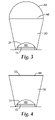
- FIG. 12 is a schematic side view illustration of a light source module including a hollow integrating tunnel type of integrating optic in accordance with another disclosed embodiment.
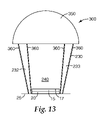
- FIG. 13 is a schematic side view illustration of another light source module embodiment including an integrating tunnel type optic.
- Disclosed embodiments provide, among other things, an efficient mechanism for extracting light from an LED light source. If desired, the disclosed embodiments can also be used for combining colors from LED emitters. These disclosed embodiments enable more compact versions of the Color-Sequential and Color-Filtering techniques by eliminating the need for the X-cube in the Color-Sequential method, and eliminating the need for anamorphic and Fresnel lenses, which have conventionally been used in both Color-Sequential and Color-Filtering methods of color projection.
- FIG. 1A of U.S. Patent Application entitled “Light Emitting Diodes with Improved Light Extraction Efficiency” (US 2002/0030194 A1).
- This illumination source includes an LED emitter in the form of a die or chip positioned on a metal header. Wire bonds provide electrical connection to the LED emitter. The emitter is bonded to a transparent optical element having a refractive index for light emitted by the active region preferably greater than about 1.5, more preferably greater than about 1.8.
- disclosed embodiments depart from conventional encapsulating techniques, and instead utilize a relatively low index medium or optic between the LED emitter and a subsequent optic.
- the benefits are similar to those described in the above reference U.S. Patent Application entitled “LED Source with Hollow Collection Lens”, and in U.S. patent application Ser. No. 11/322,801, entitled “LED With Compound Encapsulant Lens,” except that in the present disclosure the additional benefit of an integrating optic is also utilized.
- the integrating optic has a spherical cavity which provides the benefit of allowing room for wire bonds or other raised features on the surface of the LED, and also efficiently collects light from an LED having extracting features that work best with an air interface. It is often preferable to follow such air gaps with a spherical surface rather than a flat surface so as to minimize Fresnel losses, particularly for the light rays exiting the LED at very high angles. In this case minimal Fresnel losses occur for light ray incident at normal angles. Assuming the LED is a Lambertian emitter, more of the light rays exiting the die into air will be captured by a spherical surface since more of them will strike at angles close to normal.
- FIG. 1 shows schematically an exemplary embodiment of the illumination systems of the present disclosure, which may be used for projection applications.
- the light source module 10 shown in FIG. 1 includes an emitter 15 having an emitting surface 17 .
- Emitting surface 17 which may be or may include an emitting surface or surfaces of an LED, a layer of phosphor, or any other emissive material.
- the emitter 15 is positioned on a mounting surface or substrate 25 , and can optionally have a heat sink 20 positioned between the emitter 15 and the surface 25 , or elsewhere. Although shown positioned between emitter 15 and surface 25 , heat sink 20 is not required in all embodiments, nor is it necessary for the heat sink to be located in this particular position.
- Light source module 10 also includes an integrating optic 30 which is at least partially hollow mounted over emitting surface 17 of emitter 15 .
- integrating optic is a tapered rod integrator.
- Most examples described herein are with reference to tapered rod integrators 30 and 130 (described initially with reference to FIG. 7 ). However, these are only examples of integrating optics which are at least partially hollow, and other examples of such optics are also disclosed.
- tunnel integrator 230 introduced in FIG. 12 is another such integrating optic.
- mounting of integrator 30 over emitting surface 17 can be through any desired technique or configuration, including by mounting integrator 30 to other surfaces (e.g., surface 25 or a surface of heat sink 20 ).
- Tapered rod integrator 30 has a proximal end 35 and a distal end 45 .
- Proximal end 35 faces emitting surface 17
- distal end 45 faces away from the emitting surface.
- Proximal end 35 of integrator 30 provides a surface 31 that forms a spherical cavity 40 over emitter 15 .
- Distal end 45 of integrator 30 provides a surface 46 on which optical components and/or films can be positioned. Between top surface 46 and bottom surface 31 , integrator 30 has tapered sidewalls 32 and 33 .
- cavity 40 provided by tapered rod integrator is filled with a material having a refractive index, n 1 , which is less than a refractive index, n 2 , of the tapered rod integrator.
- the material in cavity 40 can be, in various embodiments, air (including any of a variety of gases or gas mixtures) or a liquid.
- the liquid can be an encapsulant gel.
- the refractive index n 1 will be close to 1.0, but can be as high as 1.5 in yet other exemplary embodiments. Other values of n 1 are also possible. Regardless of the value of n 1 , generally, n 1 will be less than n 2 .
- the refractive index n 2 of the tapered rod integrator will be at least 2.0, and generally will be around 2.4 or higher.
- emitting surface 17 has array of emitters 18 , for example emitters of differing colors.
- array of emitters 18 comprise three different colors (e.g., red, green and blue) each designated by a different cross-hatching.
- These types of multi-colored emitter arrays can utilize the color blending provided by tapered rod integrator 30 .
- tapered rod integrator 30 is not limited to emitter arrays, as integrator 30 can be used with single emitters as well.
- Emitter 15 has an aspect ratio which is the width W E of the emitter divided by the height H E of the emitter.
- End 35 of tapered rod integrator 30 which provides the spherical shaped cavity 40 also has an aspect ratio.
- FIG. 2B shows a bottom view of integrator 30 such that cavity 40 is shown.
- the aspect ratio of integrator 30 at bottom end 35 is the width W I-B of that end of the integrator divided by the height H I-B of that end of the integrator.
- the aspect ratio of integrator 30 at bottom end 35 closely matches the dimensional aspect ratio of the emitter. By closely matching, these aspect ratios can be substantially equal in exemplary embodiments.
- FIG. 2C illustrates a top view of integrator 30 such that cavity top end 45 is shown.
- the aspect ratio of integrator 30 at top end 45 is the width W I-T of that end of the integrator divided by the height H I-T of that end of the integrator.
- the aspect ratio of integrator 30 at top end 45 is a rectangular aspect ratio (even if the bottom end of integrator 30 is not rectangular).
- the rectangular aspect ratio of the top end 45 of integrator 30 does not need to closely match the aspect ratios of the emitter and of the bottom end of the integrator. This allows conversion to a desired aspect ratio to be achieved.
- Optic 50 can be any type of optical lens component chosen to achieve a particular result.
- optic 50 can include a collimating lens to aid in the production of collimated light from source 10 .
- one or several single-layer or multi-layer optical films 55 can be positioned on surface 46 of tapered rod integrator 30 to achieve desired optical results. This is illustrated for example in FIG. 4 .
- An example of an optical film which can be placed on surface 46 includes a reflective polarizing film (RPF) which can be used to produce uniformly polarized light and to facilitate light recycling.
- RPF reflective polarizing film
- a reflective polarizing film is the Vikuiti-brand multi-layer optical film (MOF) DBEF, manufactured by 3M Company, St. Paul, Minn.
- MOF Vikuiti-brand multi-layer optical film
- QWP quarter wave plate
- both RPF and QWP are included in optical film element 55 , with the QWP adjacent to surface 46 , in order to produce a greater degree of polarized light recycling.
- light source module 10 such as illustrated in FIG.
- the light source module includes the collection lens or other optic 50 adhered to the tapered rod integrator 30 via it being positioned on optical film 55 .
- mirrored sides 60 are formed from reflective materials on the side walls of integrator 30 in order to enhance total internal reflection (TIR) provided by integrator 30 and light source module 10 .
- light source module 100 which is substantially the same as light source module 10 , with the exception of certain aspects of the tapered rod integrator.
- light source module 100 includes tapered rod integrator 130 which shares many features with tapered rod integrator 30 described above.
- tapered rod integrator 130 has a proximal end 135 and a distal end 145 .
- Proximal end 135 faces emitting surface 17
- distal end 145 faces away from the emitting surface.
- Distal end 145 of integrator 130 provides a surface 146 on which optics and/or optical films can be positioned.
- the integrator 130 has tapered sidewalls 132 and 133 .
- the primary difference between integrators 30 and 130 is that cavity 140 , provided by integrator 130 and positioned over the emitting surface, is a truncated pyramidal shaped cavity instead of a spherical shaped cavity.
- the materials used to fill truncated pyramidal shaped cavity 140 can be the same as discussed above.
- optics such as collection lens 50 , optical films 55 , mirrored sides 60 , or various combinations of these types of features, can all be used with integrator 130 .
- FIG. 12 Yet another embodiment which can be used with these various features is illustrated in FIG. 12 .
- light source module 200 is shown having an integrating optic in the form of tunnel integrator 230 .
- tunnel integrator 230 the cavity 240 is extended upward to form a tunnel through tapered or non-tapered sidewalls 232 and 233 .
- the various features described above with reference to tapered rod integrators 30 and 130 can all be used with tunnel integrator 230 in the same manner.
- the sidewalls of tunnel integrator 230 can be mirrored for example.
- one or more optical films can be included with tunnel integrator 230 between the tunnel integrator and collection lens 50 .
- the contents of the cavity (e.g., the tunnel 240 ) and the refractive index relationship stipulating that the index closest to the emitter is lower than the index of subsequent optics also apply to tunnel integrator 230 embodiments.
- a particular collection lens size is shown matching the width of tunnel integrator 230 , other sizes of collection lenses can also be used. See e.g., the wider collection lens 350 used with tunnel integrator 230 in light source module 300 shown in FIG. 13 .
- FIG. 13 also illustrates mirrored sidewalls 360 , which can be either of inner or outer sidewalls in various embodiments, as was described above with regard to tapered rod integrators.
- light source modules include an emitter having at least one light emitting surface, and an at least partially hollow integrating optic mounted over the emitting surface.
- the index of refraction within the hollowed area is less then the index of refraction of the subsequent medium along the optical path.
- the at least partially hollow integrating optic has a proximal end facing the emitting surface and a distal end facing away from the emitting surface.
- the proximal end of the integrating optic has a dimensional aspect ratio closely matching a dimensional aspect ratio of the emitter, while the distal end of the integrating optic is flat with a rectangular aspect ratio.
- the rectangular aspect ratio of the distal end of the integrating optic can be different than the dimensional aspect ratio of the proximal end of the integrating optic.
- the at least partially hollow integrating optic includes a tapered rod integrator forming a cavity over the emitting surface, where the cavity has a refractive index, n 1 , less than a refractive index, n 2 , of the tapered rod integrator.
- the cavity can be, for example, a spherical or a truncated pyramidal shaped cavity.
- the cavity can be filed with air, fluid such an encapsulant gel, etc, thus providing the refractive index n 1 .
- a collection lens can be adhered to the tapered rod integrator, and the collection lens will have a refractive index which is higher than the refractive index, n 2 , of the tapered rod integrator.
- One or more optical films can also be positioned between the collection lens and a distal end of the tapered rod integrator.
- the at least partially hollow integrating optic includes a tunnel integrator mounted over the emitting surface.
- the light source modules will typically include a collection lens adhered to the tunnel integrator having an index of refraction, n 2 , greater than the index of refraction, n 1 , in the tunnel.
- the tunnel integrator has a proximal end facing the emitting surface and a distal end facing away from the emitting surface, the proximal end of the tunnel integrator forms an enclosure over the emitting surface, while the distal end of the tunnel integrator is flat with a rectangular aspect ratio.
- the collection lens is typically adhered to the distal end of the tunnel integrator.
- a color-sequential mini-projector utilizing these light source modules can include the light source modules, a polarizing beam splitter (PBS), a monochrome liquid crystal on silicon (LCOS) panel, and a projection lens.
- PBS polarizing beam splitter
- LCOS monochrome liquid crystal on silicon
- projection lens a projection lens
- a color-filter mini-projector employing the disclosed light source modules can include a PBS, a color-filter LCOS panel, and a projection lens.
- a color-sequential mini-projector system utilizing these light source modules can include the light source modules, collimating optics, a digital light processing (DLP) panel, and a projection lens.
- DLP digital light processing
Landscapes
- Physics & Mathematics (AREA)
- General Physics & Mathematics (AREA)
- Optics & Photonics (AREA)
- Projection Apparatus (AREA)
- Non-Portable Lighting Devices Or Systems Thereof (AREA)
- Optical Couplings Of Light Guides (AREA)
Priority Applications (1)
| Application Number | Priority Date | Filing Date | Title |
|---|---|---|---|
| US11/831,263 US7717599B2 (en) | 2006-07-31 | 2007-07-31 | Integrating light source module |
Applications Claiming Priority (4)
| Application Number | Priority Date | Filing Date | Title |
|---|---|---|---|
| US82088806P | 2006-07-31 | 2006-07-31 | |
| US82103206P | 2006-08-01 | 2006-08-01 | |
| US83898806P | 2006-08-21 | 2006-08-21 | |
| US11/831,263 US7717599B2 (en) | 2006-07-31 | 2007-07-31 | Integrating light source module |
Publications (2)
| Publication Number | Publication Date |
|---|---|
| US20080037271A1 US20080037271A1 (en) | 2008-02-14 |
| US7717599B2 true US7717599B2 (en) | 2010-05-18 |
Family
ID=38983903
Family Applications (1)
| Application Number | Title | Priority Date | Filing Date |
|---|---|---|---|
| US11/831,263 Expired - Fee Related US7717599B2 (en) | 2006-07-31 | 2007-07-31 | Integrating light source module |
Country Status (7)
| Country | Link |
|---|---|
| US (1) | US7717599B2 (https=) |
| EP (1) | EP2050138A2 (https=) |
| JP (1) | JP5122565B2 (https=) |
| KR (1) | KR20090035562A (https=) |
| CN (1) | CN101496170B (https=) |
| TW (1) | TW200815709A (https=) |
| WO (1) | WO2008016895A2 (https=) |
Cited By (9)
| Publication number | Priority date | Publication date | Assignee | Title |
|---|---|---|---|---|
| US20090066878A1 (en) * | 2007-09-11 | 2009-03-12 | Kenji Ogiro | Liquid Crystal Display Apparatus |
| US20100079872A1 (en) * | 2008-09-29 | 2010-04-01 | Patrick Rene Destain | Double refractive collimator |
| US20110044037A1 (en) * | 2007-05-31 | 2011-02-24 | OSRAM Opto Semicoductors GmbH | Light Source |
| US20110058350A1 (en) * | 2008-05-05 | 2011-03-10 | Phillips Iii William E | Light source module |
| US20110122371A1 (en) * | 2006-07-31 | 2011-05-26 | 3M Innovative Properties Company | Optical projection subsystem |
| US8274220B2 (en) | 2006-07-31 | 2012-09-25 | 3M Innovative Properties Company | LED source with hollow collection lens |
| US9068737B2 (en) | 2010-04-09 | 2015-06-30 | CSRAM GmbH | Lighting device |
| US10629787B2 (en) | 2016-04-08 | 2020-04-21 | Advanced Semiconductor Engineering, Inc. | Lid and an optical device package having the same |
| US20220178503A1 (en) * | 2019-08-27 | 2022-06-09 | Seoul Semiconductor Europe Gmbh | Illumination device |
Families Citing this family (20)
| Publication number | Priority date | Publication date | Assignee | Title |
|---|---|---|---|---|
| CN101442086A (zh) * | 2007-11-23 | 2009-05-27 | 富准精密工业(深圳)有限公司 | 发光二极管组合 |
| DE102009012273B4 (de) | 2008-03-14 | 2021-09-23 | Leuze Electronic Gmbh & Co. Kg | Optischer Sensor |
| DE102008002555A1 (de) * | 2008-06-20 | 2009-12-24 | Robert Bosch Gmbh | Beleuchtungseinrichtung zum Aussenden von zumindest teilweise polarisiertem Licht |
| US20100103380A1 (en) * | 2008-10-23 | 2010-04-29 | Texas Instruments Incorporated | Critical abbe illumination configuration |
| CN101988689B (zh) * | 2009-08-03 | 2012-06-13 | 杨然森 | 用于高功率led单颗多晶芯片模组路灯的光场光罩 |
| JP5436097B2 (ja) | 2009-08-25 | 2014-03-05 | 三菱電機株式会社 | 集光光学系及び投写型画像表示装置 |
| US20110057557A1 (en) * | 2009-09-08 | 2011-03-10 | Hong Kong Applied Science And Technology Research Institute Co. Ltd. | Projection led module and method of making a projection led module |
| JP2013508948A (ja) | 2009-10-14 | 2013-03-07 | スリーエム イノベイティブ プロパティズ カンパニー | 光源 |
| CN102401251A (zh) * | 2010-09-10 | 2012-04-04 | 欧司朗有限公司 | 照明装置 |
| CN102402110A (zh) * | 2010-09-15 | 2012-04-04 | 凤凰光学(上海)有限公司 | 一种三基色led发光结构 |
| FR2968745B1 (fr) | 2010-12-14 | 2012-12-07 | Valeo Systemes Thermiques | Temoin lumineux |
| TWI550310B (zh) * | 2011-09-06 | 2016-09-21 | 亞洲光學股份有限公司 | 導光件及包含該導光件之物與其製造及裝配方法 |
| US9291806B2 (en) * | 2012-06-21 | 2016-03-22 | Qualcomm Mems Technologies, Inc. | Beam pattern projector with modulating array of light sources |
| US9170474B2 (en) | 2012-06-21 | 2015-10-27 | Qualcomm Mems Technologies, Inc. | Efficient spatially modulated illumination system |
| DE102014213803A1 (de) | 2014-07-16 | 2016-01-21 | BSH Hausgeräte GmbH | Anzeigevorrichtung und Haushaltsgerät mit einer solchen Anzeigevorrichtung |
| WO2017075439A2 (en) | 2015-10-28 | 2017-05-04 | Acera LLC | Handheld mobile light source |
| US10527234B2 (en) * | 2017-01-11 | 2020-01-07 | Eaton Intelligent Power Limited | Lighting system incorporating chip scale package light emitting diodes |
| EP3905944B1 (en) | 2019-01-02 | 2025-06-04 | Acera LLC | Positioning a tube in a lumen via transillumination |
| US20230392768A1 (en) * | 2022-06-07 | 2023-12-07 | Dicon Fiberoptics, Inc. | Highly efficient light extraction system for led chip arrays |
| FR3160475A1 (fr) * | 2024-03-22 | 2025-09-26 | Valeo Comfort And Driving Assistance | Dispositif de rétro-éclairage pour un système d’affichage tête-haute |
Citations (86)
| Publication number | Priority date | Publication date | Assignee | Title |
|---|---|---|---|---|
| US5022750A (en) | 1989-08-11 | 1991-06-11 | Raf Electronics Corp. | Active matrix reflective projection system |
| US5084807A (en) | 1986-08-22 | 1992-01-28 | U.S. Philips Corporation | Illumination system for LCD projection television |
| US5108172A (en) | 1989-08-11 | 1992-04-28 | Raf Electronics Corp. | Active matrix reflective image plane module and projection system |
| US5335158A (en) * | 1992-05-21 | 1994-08-02 | Eastman Kodak Company | High efficiency linear light source |
| US5592578A (en) | 1995-11-01 | 1997-01-07 | Hewlett-Packard Company | Peripheral optical element for redirecting light from an LED |
| US5625738A (en) | 1994-06-28 | 1997-04-29 | Corning Incorporated | Apparatus for uniformly illuminating a light valve |
| US5882774A (en) | 1993-12-21 | 1999-03-16 | Minnesota Mining And Manufacturing Company | Optical film |
| US6091085A (en) | 1998-02-19 | 2000-07-18 | Agilent Technologies, Inc. | GaN LEDs with improved output coupling efficiency |
| US6200002B1 (en) | 1999-03-26 | 2001-03-13 | Philips Electronics North America Corp. | Luminaire having a reflector for mixing light from a multi-color array of leds |
| US6204523B1 (en) | 1998-11-06 | 2001-03-20 | Lumileds Lighting, U.S., Llc | High stability optical encapsulation and packaging for light-emitting diodes in the green, blue, and near UV range |
| US6246446B1 (en) | 1996-06-28 | 2001-06-12 | Texas Instruments Incorporated | Auto focus system for a SLM based image display system |
| US6328447B1 (en) | 1997-12-03 | 2001-12-11 | Seiko Epson Corporation | Projection device |
| US6337536B1 (en) | 1998-07-09 | 2002-01-08 | Sumitomo Electric Industries, Ltd. | White color light emitting diode and neutral color light emitting diode |
| US20020024640A1 (en) | 2000-08-29 | 2002-02-28 | Olympus Optical Co., Ltd. | Image projection display apparatus using plural projectors and projected image compensation apparatus |
| US20020080622A1 (en) | 2000-12-21 | 2002-06-27 | Philips Electronics North America Corporation | Faceted multi-chip package to provide a beam of uniform white light from multiple monochrome LEDs |
| US20020139984A1 (en) | 2001-01-26 | 2002-10-03 | Kabushiki Kaisha Toshiba | Semiconductor light emitting element |
| US6486499B1 (en) | 1999-12-22 | 2002-11-26 | Lumileds Lighting U.S., Llc | III-nitride light-emitting device with increased light generating capability |
| US20020180107A1 (en) | 2001-05-31 | 2002-12-05 | Jackson Jeffery N. | Processes and apparatus for making transversely drawn films with substantially uniaxial character |
| US6527411B1 (en) * | 2000-08-01 | 2003-03-04 | Visteon Corporation | Collimating lamp |
| US20030048423A1 (en) | 2001-06-11 | 2003-03-13 | Aastuen David J. W. | Projection system having low astigmatism |
| GB2383428A (en) | 2001-12-20 | 2003-06-25 | Delta Electronics Inc | Image projection of reflective display using photodiode array light source |
| US6609795B2 (en) | 2001-06-11 | 2003-08-26 | 3M Innovative Properties Company | Polarizing beam splitter |
| EP1363335A2 (en) | 2002-05-15 | 2003-11-19 | Sumitomo Electric Industries, Ltd. | White color light emitting device |
| WO2003098916A2 (en) | 2002-05-15 | 2003-11-27 | Symbol Technologies, Inc. | High-resolution image projection |
| US20030231497A1 (en) | 2002-05-10 | 2003-12-18 | Seiko Epson Corporation | Lighting system and projector |
| EP1387211A1 (en) | 2002-07-15 | 2004-02-04 | Sony International (Europe) GmbH | Image recording device combined with image projection capabilities |
| US6721096B2 (en) | 1997-10-28 | 2004-04-13 | 3M Innovative Properties Company | Polarizing beam splitter |
| US6719426B2 (en) | 2002-02-28 | 2004-04-13 | 3M Innovative Properties Company | Compound polarization beam splitters |
| US20040099992A1 (en) | 2002-11-27 | 2004-05-27 | Merrill William W. | Methods and devices for stretching polymer films |
| US20040099993A1 (en) | 2002-11-27 | 2004-05-27 | Jackson Jeffery N. | Methods and devices for processing polymer films |
| US20040140765A1 (en) | 2001-10-09 | 2004-07-22 | Agilent Technologies, Inc. | Light-emitting diode and method for its production |
| US6772265B2 (en) | 2000-12-11 | 2004-08-03 | International Business Machines Corporation | Docking station for a laptop computer |
| WO2004068602A2 (en) | 2003-01-27 | 2004-08-12 | 3M Innovative Properties Company | Phosphor based light sources having a reflective polarizer |
| US6791749B2 (en) | 2001-08-29 | 2004-09-14 | Delpico Joseph | Polarized exposure for web manufacture |
| US6793344B2 (en) | 2001-06-26 | 2004-09-21 | Integrated Microdisplays Limited | Optical systems for liquid crystal display projectors |
| US20040196518A1 (en) | 1999-08-05 | 2004-10-07 | Microvision, Inc. | Active tuning of a torsional resonant structure |
| US20040218387A1 (en) | 2003-03-18 | 2004-11-04 | Robert Gerlach | LED lighting arrays, fixtures and systems and method for determining human color perception |
| US20040227898A1 (en) | 2003-05-16 | 2004-11-18 | Jiaying Ma | Highly efficient single panel and two panel projection engines |
| US20040264185A1 (en) | 2003-04-29 | 2004-12-30 | Osram Opto Semiconductors Gmbh | Light source |
| US20050023545A1 (en) | 2003-07-31 | 2005-02-03 | Lumileds Lighting U.S., Llc | Light emitting devices with improved light extraction efficiency |
| US6856466B2 (en) | 2001-07-05 | 2005-02-15 | Science & Engineering Associates, Inc. | Multiple imaging system |
| AU2005200510A1 (en) | 2001-05-08 | 2005-03-03 | Digislide International Pty Ltd | A portable image projection device |
| US20050117366A1 (en) | 2003-12-02 | 2005-06-02 | Simbal John J. | Reflective light coupler |
| US20050135113A1 (en) | 2003-12-18 | 2005-06-23 | Harvatek Corporation | Optical projection device of a colored lighting module |
| KR20050065919A (ko) | 2003-12-26 | 2005-06-30 | 에스케이텔레텍주식회사 | 프로젝터 영상을 다양한 방향으로 주사하는 이동통신단말기 |
| US20050174771A1 (en) | 2004-02-11 | 2005-08-11 | 3M Innovative Properties Company | Reshaping light source modules and illumination systems using the same |
| US20050179041A1 (en) | 2004-02-18 | 2005-08-18 | Lumileds Lighting U.S., Llc | Illumination system with LEDs |
| WO2005077002A2 (en) | 2004-02-09 | 2005-08-25 | Northrop Grumman Corporation | Pocket-pen ultra-high resolution mems projection display in combination with on-axis ccd image capture system including means for permitting 3-d imaging |
| WO2005083804A1 (en) | 2004-01-29 | 2005-09-09 | Acol Technologies S.A. | Light emitting diode with integral heat dissipation means |
| US6961190B1 (en) | 1999-07-26 | 2005-11-01 | Labosphere Institute | Bulk lens, light emitting body, lighting device and optical information system |
| WO2005107420A2 (en) | 2004-05-05 | 2005-11-17 | Rensselaer Polytechnic Institute | High efficiency light source using solid-state emitter and down-conversion material |
| US20060007538A1 (en) | 2004-07-06 | 2006-01-12 | Colorlink Inc. | Illumination Systems |
| US20060022210A1 (en) | 2004-06-30 | 2006-02-02 | Osram Opto Semiconductors Gmbh | Radiation-emitting semiconductor chip with a beam shaping element and beam shaping element |
| US20060039140A1 (en) | 2004-08-23 | 2006-02-23 | Simon Magarill | Multiple channel illumination system |
| JP2006067469A (ja) | 2004-08-30 | 2006-03-09 | Vodafone Kk | 電子機器 |
| WO2006033245A1 (ja) | 2004-09-21 | 2006-03-30 | Nikon Corporation | 電子機器 |
| WO2006033032A1 (en) | 2004-09-24 | 2006-03-30 | Koninklijke Philips Electronics N.V. | Illumination system |
| US20060083000A1 (en) | 2004-10-18 | 2006-04-20 | Ju-Young Yoon | Light emitting diode and lens for the same |
| US20060091798A1 (en) | 2004-10-29 | 2006-05-04 | Ouderkirk Andrew J | High brightness LED package with compound optial element(s) |
| US20060091411A1 (en) | 2004-10-29 | 2006-05-04 | Ouderkirk Andrew J | High brightness LED package |
| US20060092532A1 (en) | 2004-10-29 | 2006-05-04 | Ouderkirk Andrew J | High brightness LED package with multiple optical elements |
| US20060091784A1 (en) | 2004-10-29 | 2006-05-04 | Conner Arlie R | LED package with non-bonded optical element |
| US7046338B2 (en) | 1999-01-26 | 2006-05-16 | Asml Holding N.V. | EUV condenser with non-imaging optics |
| US20060102914A1 (en) | 2004-11-15 | 2006-05-18 | Lumileds Lighting U.S., Llc | Wide emitting lens for LED useful for backlighting |
| US7059728B2 (en) | 2003-04-16 | 2006-06-13 | Upstream Engineering Oy | 2D/3D data projector |
| WO2006061763A1 (en) | 2004-12-09 | 2006-06-15 | Koninklijke Philips Electronics N.V. | Illumination system |
| US20060124918A1 (en) | 2004-12-09 | 2006-06-15 | 3M Innovative Properties Company | Polychromatic LED's and related semiconductor devices |
| US20060139580A1 (en) | 2004-12-29 | 2006-06-29 | Conner Arlie R | Illumination system using multiple light sources with integrating tunnel and projection systems using same |
| US7072096B2 (en) | 2001-12-14 | 2006-07-04 | Digital Optics International, Corporation | Uniform illumination system |
| US7101050B2 (en) | 2004-05-14 | 2006-09-05 | 3M Innovative Properties Company | Illumination system with non-radially symmetrical aperture |
| US20060221305A1 (en) | 2005-03-30 | 2006-10-05 | 3M Innovative Properties Company | Illumination system and projection system using same |
| US20060232578A1 (en) | 2004-12-21 | 2006-10-19 | Silviu Reinhorn | Collapsible portable display |
| US7133211B2 (en) | 2004-04-02 | 2006-11-07 | Integrated Microdisplays Limited | Projector with flat light sources |
| US20060262282A1 (en) | 2005-05-20 | 2006-11-23 | 3M Innovative Properties Company | Multicolor illuminator system |
| US20060262514A1 (en) | 2005-05-19 | 2006-11-23 | Conner Arlie R | Polarized, LED-based illumination source |
| US20070016199A1 (en) | 2002-08-21 | 2007-01-18 | Boehm Frank H Jr | Systems, methods and tools for spinal surgery |
| US7168820B1 (en) * | 2004-12-21 | 2007-01-30 | Djirair Minassian | Lighted vase |
| US20070023941A1 (en) | 2005-07-29 | 2007-02-01 | Duncan John E | Method for making polarizing beam splitters |
| US20070024981A1 (en) | 2005-07-29 | 2007-02-01 | Duncan John E | Polarizing beam splitter |
| US20070030456A1 (en) | 2005-07-29 | 2007-02-08 | Duncan John E | Polarizing beam splitter |
| WO2007042711A1 (fr) | 2005-10-05 | 2007-04-19 | OPTIC K (Société à Responsabilité Limitée) | Dispositif d'eclairage a diode |
| US20070153397A1 (en) | 2005-12-30 | 2007-07-05 | Destain Patrick R | Projection system with beam homogenizer |
| US20070152231A1 (en) | 2005-12-30 | 2007-07-05 | Destain Patrick R | LED with compound encapsulant lens |
| US20070153402A1 (en) | 2005-12-30 | 2007-07-05 | Destain Patrick R | Fresnel lens combination |
| US20070191506A1 (en) | 2006-02-13 | 2007-08-16 | 3M Innovative Properties Company | Curable compositions for optical articles |
| US20070188864A1 (en) | 2006-02-13 | 2007-08-16 | 3M Innovative Properties Company | Optical articles from curable compositions |
Family Cites Families (4)
| Publication number | Priority date | Publication date | Assignee | Title |
|---|---|---|---|---|
| JPH05167515A (ja) * | 1991-12-13 | 1993-07-02 | Japan Radio Co Ltd | コードレス移動電話の追跡交換処理システム |
| JPH06309842A (ja) * | 1993-04-26 | 1994-11-04 | Sony Corp | 編集装置 |
| US6488976B1 (en) * | 1999-12-13 | 2002-12-03 | Affinitea Brewing Technologies, Inc. | Method and apparatus for brewing tea with an espresso machine |
| JP2002043629A (ja) * | 2000-07-24 | 2002-02-08 | Yamakawa Akira | Led投光装置とこれに用いるレンズ体。 |
-
2007
- 2007-07-31 TW TW096128132A patent/TW200815709A/zh unknown
- 2007-07-31 EP EP07840597A patent/EP2050138A2/en not_active Withdrawn
- 2007-07-31 WO PCT/US2007/074806 patent/WO2008016895A2/en not_active Ceased
- 2007-07-31 JP JP2009523005A patent/JP5122565B2/ja not_active Expired - Fee Related
- 2007-07-31 US US11/831,263 patent/US7717599B2/en not_active Expired - Fee Related
- 2007-07-31 CN CN2007800286933A patent/CN101496170B/zh not_active Expired - Fee Related
- 2007-07-31 KR KR1020097001989A patent/KR20090035562A/ko not_active Ceased
Patent Citations (92)
| Publication number | Priority date | Publication date | Assignee | Title |
|---|---|---|---|---|
| US5084807A (en) | 1986-08-22 | 1992-01-28 | U.S. Philips Corporation | Illumination system for LCD projection television |
| US5022750A (en) | 1989-08-11 | 1991-06-11 | Raf Electronics Corp. | Active matrix reflective projection system |
| US5108172A (en) | 1989-08-11 | 1992-04-28 | Raf Electronics Corp. | Active matrix reflective image plane module and projection system |
| US5335158A (en) * | 1992-05-21 | 1994-08-02 | Eastman Kodak Company | High efficiency linear light source |
| US5882774A (en) | 1993-12-21 | 1999-03-16 | Minnesota Mining And Manufacturing Company | Optical film |
| US5962114A (en) | 1993-12-21 | 1999-10-05 | 3M Innovative Properties Company | Polarizing beam-splitting optical component |
| US5625738A (en) | 1994-06-28 | 1997-04-29 | Corning Incorporated | Apparatus for uniformly illuminating a light valve |
| US5592578A (en) | 1995-11-01 | 1997-01-07 | Hewlett-Packard Company | Peripheral optical element for redirecting light from an LED |
| US6246446B1 (en) | 1996-06-28 | 2001-06-12 | Texas Instruments Incorporated | Auto focus system for a SLM based image display system |
| US6721096B2 (en) | 1997-10-28 | 2004-04-13 | 3M Innovative Properties Company | Polarizing beam splitter |
| US6328447B1 (en) | 1997-12-03 | 2001-12-11 | Seiko Epson Corporation | Projection device |
| US6091085A (en) | 1998-02-19 | 2000-07-18 | Agilent Technologies, Inc. | GaN LEDs with improved output coupling efficiency |
| US6337536B1 (en) | 1998-07-09 | 2002-01-08 | Sumitomo Electric Industries, Ltd. | White color light emitting diode and neutral color light emitting diode |
| US6590235B2 (en) | 1998-11-06 | 2003-07-08 | Lumileds Lighting, U.S., Llc | High stability optical encapsulation and packaging for light-emitting diodes in the green, blue, and near UV range |
| US6204523B1 (en) | 1998-11-06 | 2001-03-20 | Lumileds Lighting, U.S., Llc | High stability optical encapsulation and packaging for light-emitting diodes in the green, blue, and near UV range |
| US7046338B2 (en) | 1999-01-26 | 2006-05-16 | Asml Holding N.V. | EUV condenser with non-imaging optics |
| US6200002B1 (en) | 1999-03-26 | 2001-03-13 | Philips Electronics North America Corp. | Luminaire having a reflector for mixing light from a multi-color array of leds |
| US6961190B1 (en) | 1999-07-26 | 2005-11-01 | Labosphere Institute | Bulk lens, light emitting body, lighting device and optical information system |
| US20040196518A1 (en) | 1999-08-05 | 2004-10-07 | Microvision, Inc. | Active tuning of a torsional resonant structure |
| US6486499B1 (en) | 1999-12-22 | 2002-11-26 | Lumileds Lighting U.S., Llc | III-nitride light-emitting device with increased light generating capability |
| US6527411B1 (en) * | 2000-08-01 | 2003-03-04 | Visteon Corporation | Collimating lamp |
| US20020024640A1 (en) | 2000-08-29 | 2002-02-28 | Olympus Optical Co., Ltd. | Image projection display apparatus using plural projectors and projected image compensation apparatus |
| US6772265B2 (en) | 2000-12-11 | 2004-08-03 | International Business Machines Corporation | Docking station for a laptop computer |
| US20020080622A1 (en) | 2000-12-21 | 2002-06-27 | Philips Electronics North America Corporation | Faceted multi-chip package to provide a beam of uniform white light from multiple monochrome LEDs |
| US20020139984A1 (en) | 2001-01-26 | 2002-10-03 | Kabushiki Kaisha Toshiba | Semiconductor light emitting element |
| AU2005200510A1 (en) | 2001-05-08 | 2005-03-03 | Digislide International Pty Ltd | A portable image projection device |
| US20020180107A1 (en) | 2001-05-31 | 2002-12-05 | Jackson Jeffery N. | Processes and apparatus for making transversely drawn films with substantially uniaxial character |
| US20020190406A1 (en) | 2001-05-31 | 2002-12-19 | Merrill William Ward | Processes and apparatus for making transversely drawn films with substantially uniaxial character |
| US6609795B2 (en) | 2001-06-11 | 2003-08-26 | 3M Innovative Properties Company | Polarizing beam splitter |
| US20030048423A1 (en) | 2001-06-11 | 2003-03-13 | Aastuen David J. W. | Projection system having low astigmatism |
| US6793344B2 (en) | 2001-06-26 | 2004-09-21 | Integrated Microdisplays Limited | Optical systems for liquid crystal display projectors |
| US6856466B2 (en) | 2001-07-05 | 2005-02-15 | Science & Engineering Associates, Inc. | Multiple imaging system |
| US6791749B2 (en) | 2001-08-29 | 2004-09-14 | Delpico Joseph | Polarized exposure for web manufacture |
| US20040140765A1 (en) | 2001-10-09 | 2004-07-22 | Agilent Technologies, Inc. | Light-emitting diode and method for its production |
| US7072096B2 (en) | 2001-12-14 | 2006-07-04 | Digital Optics International, Corporation | Uniform illumination system |
| GB2383428A (en) | 2001-12-20 | 2003-06-25 | Delta Electronics Inc | Image projection of reflective display using photodiode array light source |
| US6719426B2 (en) | 2002-02-28 | 2004-04-13 | 3M Innovative Properties Company | Compound polarization beam splitters |
| US20030231497A1 (en) | 2002-05-10 | 2003-12-18 | Seiko Epson Corporation | Lighting system and projector |
| EP1363335A2 (en) | 2002-05-15 | 2003-11-19 | Sumitomo Electric Industries, Ltd. | White color light emitting device |
| WO2003098916A2 (en) | 2002-05-15 | 2003-11-27 | Symbol Technologies, Inc. | High-resolution image projection |
| EP1387211A1 (en) | 2002-07-15 | 2004-02-04 | Sony International (Europe) GmbH | Image recording device combined with image projection capabilities |
| US20070016199A1 (en) | 2002-08-21 | 2007-01-18 | Boehm Frank H Jr | Systems, methods and tools for spinal surgery |
| US20040099993A1 (en) | 2002-11-27 | 2004-05-27 | Jackson Jeffery N. | Methods and devices for processing polymer films |
| US20040099992A1 (en) | 2002-11-27 | 2004-05-27 | Merrill William W. | Methods and devices for stretching polymer films |
| WO2004068602A2 (en) | 2003-01-27 | 2004-08-12 | 3M Innovative Properties Company | Phosphor based light sources having a reflective polarizer |
| US20040218387A1 (en) | 2003-03-18 | 2004-11-04 | Robert Gerlach | LED lighting arrays, fixtures and systems and method for determining human color perception |
| US7059728B2 (en) | 2003-04-16 | 2006-06-13 | Upstream Engineering Oy | 2D/3D data projector |
| US20040264185A1 (en) | 2003-04-29 | 2004-12-30 | Osram Opto Semiconductors Gmbh | Light source |
| US20040227898A1 (en) | 2003-05-16 | 2004-11-18 | Jiaying Ma | Highly efficient single panel and two panel projection engines |
| US20050023545A1 (en) | 2003-07-31 | 2005-02-03 | Lumileds Lighting U.S., Llc | Light emitting devices with improved light extraction efficiency |
| US20050117366A1 (en) | 2003-12-02 | 2005-06-02 | Simbal John J. | Reflective light coupler |
| US20050135113A1 (en) | 2003-12-18 | 2005-06-23 | Harvatek Corporation | Optical projection device of a colored lighting module |
| KR20050065919A (ko) | 2003-12-26 | 2005-06-30 | 에스케이텔레텍주식회사 | 프로젝터 영상을 다양한 방향으로 주사하는 이동통신단말기 |
| WO2005083804A1 (en) | 2004-01-29 | 2005-09-09 | Acol Technologies S.A. | Light emitting diode with integral heat dissipation means |
| WO2005077002A2 (en) | 2004-02-09 | 2005-08-25 | Northrop Grumman Corporation | Pocket-pen ultra-high resolution mems projection display in combination with on-axis ccd image capture system including means for permitting 3-d imaging |
| WO2005078496A2 (en) | 2004-02-11 | 2005-08-25 | 3M Innovative Properties Company | Reshaping light source modules and illumination systems using the same |
| US20050174771A1 (en) | 2004-02-11 | 2005-08-11 | 3M Innovative Properties Company | Reshaping light source modules and illumination systems using the same |
| US20050179041A1 (en) | 2004-02-18 | 2005-08-18 | Lumileds Lighting U.S., Llc | Illumination system with LEDs |
| US7133211B2 (en) | 2004-04-02 | 2006-11-07 | Integrated Microdisplays Limited | Projector with flat light sources |
| WO2005107420A2 (en) | 2004-05-05 | 2005-11-17 | Rensselaer Polytechnic Institute | High efficiency light source using solid-state emitter and down-conversion material |
| US7101050B2 (en) | 2004-05-14 | 2006-09-05 | 3M Innovative Properties Company | Illumination system with non-radially symmetrical aperture |
| US20060022210A1 (en) | 2004-06-30 | 2006-02-02 | Osram Opto Semiconductors Gmbh | Radiation-emitting semiconductor chip with a beam shaping element and beam shaping element |
| US20060007538A1 (en) | 2004-07-06 | 2006-01-12 | Colorlink Inc. | Illumination Systems |
| US20060039140A1 (en) | 2004-08-23 | 2006-02-23 | Simon Magarill | Multiple channel illumination system |
| JP2006067469A (ja) | 2004-08-30 | 2006-03-09 | Vodafone Kk | 電子機器 |
| WO2006033245A1 (ja) | 2004-09-21 | 2006-03-30 | Nikon Corporation | 電子機器 |
| WO2006033032A1 (en) | 2004-09-24 | 2006-03-30 | Koninklijke Philips Electronics N.V. | Illumination system |
| US20060083000A1 (en) | 2004-10-18 | 2006-04-20 | Ju-Young Yoon | Light emitting diode and lens for the same |
| US20060091798A1 (en) | 2004-10-29 | 2006-05-04 | Ouderkirk Andrew J | High brightness LED package with compound optial element(s) |
| US20060091784A1 (en) | 2004-10-29 | 2006-05-04 | Conner Arlie R | LED package with non-bonded optical element |
| US20060092532A1 (en) | 2004-10-29 | 2006-05-04 | Ouderkirk Andrew J | High brightness LED package with multiple optical elements |
| US20060091411A1 (en) | 2004-10-29 | 2006-05-04 | Ouderkirk Andrew J | High brightness LED package |
| US20060102914A1 (en) | 2004-11-15 | 2006-05-18 | Lumileds Lighting U.S., Llc | Wide emitting lens for LED useful for backlighting |
| WO2006061763A1 (en) | 2004-12-09 | 2006-06-15 | Koninklijke Philips Electronics N.V. | Illumination system |
| US20060124918A1 (en) | 2004-12-09 | 2006-06-15 | 3M Innovative Properties Company | Polychromatic LED's and related semiconductor devices |
| US20060232578A1 (en) | 2004-12-21 | 2006-10-19 | Silviu Reinhorn | Collapsible portable display |
| US7168820B1 (en) * | 2004-12-21 | 2007-01-30 | Djirair Minassian | Lighted vase |
| US20060139580A1 (en) | 2004-12-29 | 2006-06-29 | Conner Arlie R | Illumination system using multiple light sources with integrating tunnel and projection systems using same |
| US20060221305A1 (en) | 2005-03-30 | 2006-10-05 | 3M Innovative Properties Company | Illumination system and projection system using same |
| WO2006124993A1 (en) | 2005-05-19 | 2006-11-23 | 3M Innovative Properties Company | Polarized, led-based illumination source |
| US20060262514A1 (en) | 2005-05-19 | 2006-11-23 | Conner Arlie R | Polarized, LED-based illumination source |
| US20060262282A1 (en) | 2005-05-20 | 2006-11-23 | 3M Innovative Properties Company | Multicolor illuminator system |
| US20070023941A1 (en) | 2005-07-29 | 2007-02-01 | Duncan John E | Method for making polarizing beam splitters |
| US20070024981A1 (en) | 2005-07-29 | 2007-02-01 | Duncan John E | Polarizing beam splitter |
| US20070030456A1 (en) | 2005-07-29 | 2007-02-08 | Duncan John E | Polarizing beam splitter |
| US20070085973A1 (en) | 2005-07-29 | 2007-04-19 | 3M Innovative Properties Company | Polarizing beam splitter |
| WO2007042711A1 (fr) | 2005-10-05 | 2007-04-19 | OPTIC K (Société à Responsabilité Limitée) | Dispositif d'eclairage a diode |
| US20070153397A1 (en) | 2005-12-30 | 2007-07-05 | Destain Patrick R | Projection system with beam homogenizer |
| US20070152231A1 (en) | 2005-12-30 | 2007-07-05 | Destain Patrick R | LED with compound encapsulant lens |
| US20070153402A1 (en) | 2005-12-30 | 2007-07-05 | Destain Patrick R | Fresnel lens combination |
| US20070191506A1 (en) | 2006-02-13 | 2007-08-16 | 3M Innovative Properties Company | Curable compositions for optical articles |
| US20070188864A1 (en) | 2006-02-13 | 2007-08-16 | 3M Innovative Properties Company | Optical articles from curable compositions |
Non-Patent Citations (23)
| Title |
|---|
| "Digismart Miniature Projection Technology" http://www.digislide.com.au/consumer/digismart.htm. |
| "TI Pushing DLP into Mobile Phase" http://www.dailytech.com/article.aspx?newsid=5671. |
| Data Management White Papers, silicon.com, http://whitepapers.silicon.com/0,39024759,60243129p-39000676q,00.htm, downloaded Jul. 13, 2007. |
| Destain, Patrick; Opcon Associates Inc., Description of the Mini-projection Optical design, Jan. 23, 2006. |
| DigiTimes daliy IT news, TI shows projection image for mobile phone, http://www.digitimes.com/NewsShow/MailHome.asp?datePublish=2007/3/27&pages=VL&seq=207, Mar. 28, 2007. |
| Hoelen, C. et al., "Multi-chip color variable LED spot modules", Proceedings of the SPIE, SPIR, Bellingham, VA, US, vol. 5941, Aug. 2, 2005, pp. 59410A-1. |
| Lo, H, et al.; P-208: Novel Optical Design for Mini Projector, SID 06 Digest. pp. 1012-1014, 2006. |
| U.S. Appl. No. 11/381,518, filed May 3, 2006. |
| U.S. Appl. No. 11/457,599, filed Jul. 14, 2006. |
| U.S. Appl. No. 11/772,609, filed Jul. 2, 2007. |
| U.S. Appl. No. 11/831,171, filed Jul. 31, 2007. |
| U.S. Appl. No. 11/831,198, filed Jul. 31, 2007. |
| U.S. Appl. No. 11/831,220, filed Jul. 31, 2007. |
| U.S. Appl. No. 11/831,263, filed Jul. 31, 2007. |
| U.S. Appl. No. 11/831,307, filed Jul. 31, 2007. |
| U.S. Appl. No. 60/820,877, filed Jul. 31, 2006. |
| U.S. Appl. No. 60/820,883, filed Jul. 31, 2006. |
| U.S. Appl. No. 60/820,887, filed Jul. 31, 2006. |
| U.S. Appl. No. 60/820,888, filed Jul. 31, 2006. |
| U.S. Appl. No. 60/820,894, filed Jul. 31, 2006. |
| U.S. Appl. No. 60/821,032, filed Aug. 1, 2006. |
| U.S. Appl. No. 60/838,988, filed Aug. 21, 2006. |
| Zou, Hans et al.; 58.1: Single-Panel LCOS Color Projector with LED Light Sources, SID 05 Digest, pp. 1698-1701, 2005. |
Cited By (19)
| Publication number | Priority date | Publication date | Assignee | Title |
|---|---|---|---|---|
| US8274220B2 (en) | 2006-07-31 | 2012-09-25 | 3M Innovative Properties Company | LED source with hollow collection lens |
| US8459800B2 (en) | 2006-07-31 | 2013-06-11 | 3M Innovative Properties Company | Optical projection subsystem |
| US20110122371A1 (en) * | 2006-07-31 | 2011-05-26 | 3M Innovative Properties Company | Optical projection subsystem |
| US8070295B2 (en) | 2006-07-31 | 2011-12-06 | 3M Innovative Properties Company | Optical projection subsystem |
| US8944657B2 (en) * | 2007-05-31 | 2015-02-03 | Osram Opto Semiconductors Gmbh | Light source |
| US20110044037A1 (en) * | 2007-05-31 | 2011-02-24 | OSRAM Opto Semicoductors GmbH | Light Source |
| US20090066878A1 (en) * | 2007-09-11 | 2009-03-12 | Kenji Ogiro | Liquid Crystal Display Apparatus |
| US8382293B2 (en) | 2008-05-05 | 2013-02-26 | 3M Innovative Properties Company | Light source module |
| US20110058350A1 (en) * | 2008-05-05 | 2011-03-10 | Phillips Iii William E | Light source module |
| US7843654B2 (en) * | 2008-09-29 | 2010-11-30 | Texas Instruments Incorporated | Collecting lens |
| US20100079872A1 (en) * | 2008-09-29 | 2010-04-01 | Patrick Rene Destain | Double refractive collimator |
| US9068737B2 (en) | 2010-04-09 | 2015-06-30 | CSRAM GmbH | Lighting device |
| US10629787B2 (en) | 2016-04-08 | 2020-04-21 | Advanced Semiconductor Engineering, Inc. | Lid and an optical device package having the same |
| US20220178503A1 (en) * | 2019-08-27 | 2022-06-09 | Seoul Semiconductor Europe Gmbh | Illumination device |
| US11739891B2 (en) * | 2019-08-27 | 2023-08-29 | Seoul Semiconductor Europe Gmbh | Illumination device |
| US20230358373A1 (en) * | 2019-08-27 | 2023-11-09 | Seoul Semiconductor Europe Gmbh | Illumination device |
| US11940104B2 (en) * | 2019-08-27 | 2024-03-26 | Seoul Semiconductor Europe Gmbh | Illumination device |
| US20240310011A1 (en) * | 2019-08-27 | 2024-09-19 | Seoul Semiconductor Europe Gmbh | Illumination device |
| US12234955B2 (en) * | 2019-08-27 | 2025-02-25 | Seoul Semiconductor Europe Gmbh | Illumination device |
Also Published As
| Publication number | Publication date |
|---|---|
| JP2009545893A (ja) | 2009-12-24 |
| JP5122565B2 (ja) | 2013-01-16 |
| EP2050138A2 (en) | 2009-04-22 |
| US20080037271A1 (en) | 2008-02-14 |
| WO2008016895A3 (en) | 2008-06-26 |
| CN101496170B (zh) | 2011-06-29 |
| KR20090035562A (ko) | 2009-04-09 |
| WO2008016895A2 (en) | 2008-02-07 |
| TW200815709A (en) | 2008-04-01 |
| CN101496170A (zh) | 2009-07-29 |
Similar Documents
| Publication | Publication Date | Title |
|---|---|---|
| US7717599B2 (en) | Integrating light source module | |
| CN100510947C (zh) | 照明装置及投射式影像显示装置 | |
| JP4524265B2 (ja) | 照明ユニット及びそれを採用した画像投射装置 | |
| US20060139580A1 (en) | Illumination system using multiple light sources with integrating tunnel and projection systems using same | |
| US20050179041A1 (en) | Illumination system with LEDs | |
| JP2005326855A (ja) | 電気的切替え式および角度で分離されている色チャンネルを有するプロジェクタ | |
| JP2005227339A (ja) | 光源装置、光源装置製造方法、及びプロジェクタ | |
| TW200536147A (en) | Light-collecting illumination system | |
| JP7206628B2 (ja) | 発光装置およびプロジェクター | |
| JP2007288169A (ja) | 光学素子、照明装置および画像表示装置 | |
| KR20090037901A (ko) | 중공 집광 렌즈를 갖는 led 광원 | |
| CN1918498A (zh) | 改形光源组件以及使用该组件的照明系统 | |
| TW200425548A (en) | Light-source | |
| JP2004053949A (ja) | 光源装置及び投写型表示装置 | |
| US11508874B2 (en) | Light emitting apparatus and projector | |
| US20080123343A1 (en) | Light source device, image display device, optical element and manufacturing method thereof | |
| CN102575829A (zh) | 光源 | |
| US20070242231A1 (en) | Illumination system and projection apparatus | |
| Krijn et al. | LED-based mini-projectors | |
| US7976200B2 (en) | Optical projection device | |
| JP2008026853A (ja) | 光源装置及び画像表示装置 | |
| JP2000305171A (ja) | 照明装置及び投射型表示装置 | |
| CN118887881A (zh) | 微型led投影器 | |
| JP4815301B2 (ja) | 光源モジュール及び投影型表示装置 | |
| CN115561958B (zh) | 微投影显示与摄像光学模组一体化的层叠式光学引擎结构 |
Legal Events
| Date | Code | Title | Description |
|---|---|---|---|
| AS | Assignment |
Owner name: 3M INNOVATIVE PROPERTIES COMPANY, MINNESOTA Free format text: ASSIGNMENT OF ASSIGNORS INTEREST;ASSIGNORS:GRACE, JENNIFER L.;DESTAIN, PATRICK R.;PHILLIPS, WILLIAM E. III;REEL/FRAME:020063/0450;SIGNING DATES FROM 20071018 TO 20071022 Owner name: 3M INNOVATIVE PROPERTIES COMPANY,MINNESOTA Free format text: ASSIGNMENT OF ASSIGNORS INTEREST;ASSIGNORS:GRACE, JENNIFER L.;DESTAIN, PATRICK R.;PHILLIPS, WILLIAM E. III;SIGNING DATES FROM 20071018 TO 20071022;REEL/FRAME:020063/0450 |
|
| REMI | Maintenance fee reminder mailed | ||
| LAPS | Lapse for failure to pay maintenance fees | ||
| STCH | Information on status: patent discontinuation |
Free format text: PATENT EXPIRED DUE TO NONPAYMENT OF MAINTENANCE FEES UNDER 37 CFR 1.362 |
|
| STCH | Information on status: patent discontinuation |
Free format text: PATENT EXPIRED DUE TO NONPAYMENT OF MAINTENANCE FEES UNDER 37 CFR 1.362 |
|
| FP | Lapsed due to failure to pay maintenance fee |
Effective date: 20140518 |