US7712583B2 - Method and apparatus for controlling automatic lifting and lowering type platform - Google Patents
Method and apparatus for controlling automatic lifting and lowering type platform Download PDFInfo
- Publication number
- US7712583B2 US7712583B2 US11/233,328 US23332805A US7712583B2 US 7712583 B2 US7712583 B2 US 7712583B2 US 23332805 A US23332805 A US 23332805A US 7712583 B2 US7712583 B2 US 7712583B2
- Authority
- US
- United States
- Prior art keywords
- automatic
- lowering
- power generating
- mobile power
- generating apparatus
- Prior art date
- Legal status (The legal status is an assumption and is not a legal conclusion. Google has not performed a legal analysis and makes no representation as to the accuracy of the status listed.)
- Expired - Fee Related, expires
Links
Images


Classifications
-
- B—PERFORMING OPERATIONS; TRANSPORTING
- B66—HOISTING; LIFTING; HAULING
- B66F—HOISTING, LIFTING, HAULING OR PUSHING, NOT OTHERWISE PROVIDED FOR, e.g. DEVICES WHICH APPLY A LIFTING OR PUSHING FORCE DIRECTLY TO THE SURFACE OF A LOAD
- B66F7/00—Lifting frames, e.g. for lifting vehicles; Platform lifts
- B66F7/10—Lifting frames, e.g. for lifting vehicles; Platform lifts with platforms supported directly by jacks
- B66F7/16—Lifting frames, e.g. for lifting vehicles; Platform lifts with platforms supported directly by jacks by one or more hydraulic or pneumatic jacks
- B66F7/20—Lifting frames, e.g. for lifting vehicles; Platform lifts with platforms supported directly by jacks by one or more hydraulic or pneumatic jacks by several jacks with means for maintaining the platforms horizontal during movement
Definitions
- the present invention relates to an automatic lifting and lowering controlling method that serves in installation of a heavy machine, such as a mobile power generating apparatus, or the like, on or removal thereof from a desired site, and an automatic lift/lower type platform controlling apparatus which is to be directly used for implementing the method.
- the power generator is accommodated in a bonnet type (box type) container for reinforcement, and protection against outdoor weather, and minimization of the noise from the power generator; that the loading and unloading is performed by a crane to suspend the platform (also called chassis, bed, or base), on which the container is loaded, at the four side points thereof; and that, as the frame structural material on both sides of the platform, a channel steel material is used to provide a necessary strength.
- a bonnet type box type
- an automatic lifting/lowering platform apparatus A′ as shown in FIG. 10 , which eliminates the need for lashing work, has been developed, allowing reduction of size of the mobile power generating apparatus; loading and unloading by a small number of crew members who are not limited to the qualified personnel, and thus reduction in the necessary numbers of working crew members; elimination of the hazard to the crew by a possible drop of load during operation of the crane, and the possibility of the load being damaged by dropping; and reduction of the working area required for transfer to or from the installation site.
- Patent literature 1 Japanese Laid-Open Publication No. 2000-134729
- the automatic lifting/lowering platform apparatus A′ as disclosed in the patent literature 1 has presented such problems as that, due to the difference in distance from the single pressure source to the respective jacks as automatic lifting and lowering means, the pressure loss and the pressure transfer rate vary, resulting in differences in operation timing and operation speed between jacks, and thus the vertical positions of the respective jacks vary, which can cause an inclination to be generated in automatic lifting or automatic lowering of the power generator, and thus a strain or a torsion to be produced, resulting in the joint waterproofing material on the outer plate panel being peeled off, which may lead to rainwater entering the interior and the door becoming impossible to be opened.
- the inclination of the entire power generating apparatus can be easily verified at a location distant to some degree therefrom, however, the system with which the solenoid directional control valves are directly operated near the machine, the angle of the inclination cannot easily be recognized (the tardiness of angle recognition), which, in some cases, has led to an unnecessary inclination, and increased the shock load.
- the tardiness of angle recognition involved in the operation near the machine might cause overturning of the machine, resulting in the operator himself being injured by the overturned machine, thus with this system, the operator must have had to repeat a slight adjustment, and “a patrol around and inspection of the entire machine”.
- a first purpose of the present invention is to provide an automatic lifting and lowering controlling method and an automatic lift/lower type platform controlling apparatus for mobile power generating apparatus, or the like, that, in an automatic lifting/lowering operation on a mobile power generating apparatus, or the like, generate no strain and torsion which may cause failure or trouble of the apparatus.
- a second purpose of the present invention is to provide an automatic lifting and lowering controlling method and an automatic lift/lower type platform controlling apparatus for mobile power generating apparatus, or the like, that can be reinforced against possible failure and vibration, while being lightweight.
- a fourth purpose of the present invention is to provide an automatic lifting and lowering controlling method and an automatic lift/lower type platform controlling apparatus for mobile power generating apparatus, or the like, that can be used and operated by any personnel, and that allow safely carrying out of automatic lifting/lowering of a mobile power generating apparatus, or the like.
- the apparatus of the present invention provides means of an automatic lift/lower type platform controlling apparatus comprising a chassis which is integrally formed with a mobile power generating apparatus, or the like, or on which a mobile power generating apparatus, or the like, is to be loaded for serving a desired purpose on a desired site; outriggers which are extended or drawn in in the horizontal direction from or into both sides at both ends of the chassis, incorporating a jack, respectively; a vertical outer case in the outriggers; a vertical inner case which is inserted into the vertical outer case, and extended or drawn in in the vertical direction; an angle sensor for inclination correction that detects the inclination in the front, rear, right, and left directions of said chassis; an allotter which causes the deviations detected by the angle sensor to be reflected to said respective jacks; and a remote wireless control operating apparatus for wirelessly operating from the outside.
- the present invention adopts novel characteristic configuration methods and means listed below that range from the high order of concept to the low order thereof for achieving said purposes.
- a second aspect of the present invention is configured to provide the automatic lifting and lowering controlling method for mobile power generating apparatus, or the like, of the first aspect, wherein said automatic lifting and lowering means performs said automatic lifting/lowering operation, a torque tube being used as a frame structural material for a chassis in which the automatic lifting and lowering means is mounted in order to increase the torsion strength and the strain strength without the need for increasing the weight of reinforcement, and eliminate the problems arising from an inclination torsion or strain caused by a deviation in operation timing and speed between said respective automatic lifting and lowering means.
- a third aspect of the present invention is configured to provide the automatic lifting and lowering controlling method for mobile power generating apparatus, or the like, of the first aspect or the second aspect, wherein said automatic leveler means essentially consists of a combination of an angle sensor for inclination correction, and an allotter for receiving a signal from the angle sensor to make ON/OFF control of the automatic lifting and lowering means for level adjustment operation, and as soon as the angle sensor detects that particular automatic lifting and lowering means or a particular set of automatic lifting and lowering means produces a deviation of true level that exceeds an allowable limit, stops the particular automatic lifting and lowering means, adjusting the operation of the other automatic lifting and lowering means or the particular set of automatic lifting and lowering means for restoring the levelness of said automatic lift/lower type platform controlling apparatus, then resuming the automatic lifting of automatic lowering.
- a fourth aspect of the present invention is configured to provide the automatic lifting and lowering controlling method for mobile power generating apparatus, or the like, of the third aspect, wherein said automatic leveler means introduces open-close signals for the four points, right and left and front and rear, corresponding to said respective automatic lifting and lowering means into the allotter, and by causing said respective automatic lifting and lowering means to follow the control for level adjustment, automatically carries out the level correction of the inclination of said torque tube chassis in the diagonal directions and at the four sides thereof safely and with a minimum of shock in automatic lifting or automatic lowering.
- a fifth aspect of the present invention is configured to provide the automatic lifting and lowering controlling method for mobile power generating apparatus, or the like, of the first aspect, the second aspect, the third aspect, or the fourth aspect, wherein said automatic lifting and lowering means is wirelessly controlled by the operator using a wireless control apparatus to select any one of the two channels for lifting or lowering.
- a sixth aspect of the present invention is configured to provide an automatic lift/lower type platform controlling apparatus for mobile power generating apparatus, or the like, wherein the automatic lift/lower type platform controlling apparatus is an apparatus for carrying out an automatic lifting/lowering operation for installation or removal of a mobile power generating apparatus, or the like, on or from a desired site, comprising: a chassis which is a platform on which the mobile power generating apparatus, or the like, is to be loaded or which is integrated with the mobile power generating apparatus, or the like; a plurality of outriggers which are mounted on both sides of the chassis so as to be extended or drawn in in the horizontal direction in lifting or lowering operation; an automatic leveler for automatically detecting the inclination of said mobile power generating apparatus, or the like, in the front, rear, right, or left direction; directional control/open-close valves provided in parallel pressure circuits for supply and return that connect between a single pressure source and the hydraulic cylinder in said respective outriggers for allowing selection of either supply or return circuit, and performing open-close operation on the
- a seventh aspect of the present invention is configured to provide the automatic lift/lower type platform controlling apparatus for mobile power generating apparatus, or the like, of the sixth aspect, wherein said automatic leveler essentially consists of: a square angle sensor which is to be disposed at the center of the bottom of said mobile power generating apparatus, or the like, with the four corners being oriented to the front, rear, right, and left directions of the mobile power generating apparatus, or the like, respectively, and issuing inclination signals corresponding to said outriggers, respectively; and an allotter which receives the respective inclination signals from the angle sensor, and automatically allots a level adjustment ON/OFF operation signal to said respective directional control/open-close valves connected to the jacks incorporated in the outriggers, respectively.
- said automatic leveler essentially consists of: a square angle sensor which is to be disposed at the center of the bottom of said mobile power generating apparatus, or the like, with the four corners being oriented to the front, rear, right, and left directions of the mobile power generating
- An eighth aspect of the present invention is configured to provide the automatic lift/lower type platform controlling apparatus for mobile power generating apparatus, or the like, of the sixth aspect or the seventh aspect, wherein, for said chassis, a torque tube which is resistant to a torsion or strain generated in automatic lifting/lowering is adopted as a frame structural material.
- a ninth aspect of the present invention is configured to provide the automatic lift/lower type platform controlling apparatus for mobile power generating apparatus, or the like, of the seventh aspect or the eighth aspect, wherein said allotter is functionally configured to issue a lifting/lowering command signal to said all directional control/open-close valves, being connected to a wireless control apparatus for selecting either of the two directions of lifting and lowering to operation-control said all jacks.
- a tenth aspect of the present invention is configured to provide the automatic lift/lower type platform controlling apparatus for mobile power generating apparatus, or the like, of the ninth aspect, wherein said wireless control apparatus essentially consists of a combination of a transmitter having lifting and lowering two-channel operation switches and a receiver which receives a single channel signal from the transmitter to transmit either of the lifting and lowering signals to said allotter.
- a torque tube for reinforcement of the chassis allows the automatic lift/lower type platform controlling apparatus to be reinforced without the need for increasing the size, and eliminates the possible problems that some component parts of the mobile power generating apparatus may be subjected to a deformation pressure by a container wall plate or the platform, and that the maintenability may be adversely affected.
- the inclination correction by the automatic leveler in the apparatus of the present invention allows carrying out automatic lifting and automatic lowering of the mobile power generating apparatus while maintaining the level in installation and removal of the mobile power generating apparatus, and by using the angle sensor for automatically performing the inclination correction, the possible problems that dropping, overturning, failure, and the like, of the mobile power generating apparatus may occur can be eliminated, with the safety of the crew members being assured.
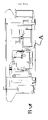
- FIG. 1 is a perspective side view illustrating the configuration of the automatic lifting/lowering platform mechanism part of the automatic lift/lower type platform controlling apparatus for mobile power generating apparatus, or the like, that pertains to an example of apparatus of the present invention
- FIG. 2 ( a ), FIG. 2 ( b ), and FIG. 2 ( c ) are explanatory drawings for an angle sensor pertaining to an example of apparatus of the present invention, FIG. 2 ( a ) being a plan view, FIG. 2 ( b ) a side view, and FIG. 2 ( c ) a front view;
- FIG. 3 is a perspective front view illustrating the mounting location for the angle sensor in a mobile power generating apparatus, or the like, that pertains to an example of apparatus of the present invention
- FIG. 4 is a configuration diagram for a drive control circuit comprising an automatic leveler essentially consisting of an angle sensor and an allotter pertaining to an example of apparatus of the present invention
- FIG. 5 ( a ) and FIG. 5 ( b ) are diagrams illustrating the respective operation of solenoid directional control/open-close valves pertaining to an example of apparatus of the present invention, FIG. 5 ( a ) illustrating the point displacement of a jack, while FIG. 5 ( b ) illustrating the line displacement of two jacks;
- FIG. 6 ( a ) and FIG. 6 ( b ) are appearance drawings of a mobile power generating apparatus, FIG. 6 ( a ) being a plan view while FIG. 6 ( b ) a right side view;
- FIG. 7 ( a ) is an explanatory drawing illustrating the method of loading of a mobile power generating apparatus onto the cargo truck load-carrying platform with the outriggers in the automatic lift/lower type platform controlling apparatus pertaining to an example of apparatus of the present invention being extended, giving a back view; and FIG. 7 ( b ) is a back view of the mobile power generating apparatus loaded on the automatic lift/lower type platform controlling apparatus;
- FIG. 8 ( a ) and FIG. 8 ( b ) are explanatory drawings illustrating the tension imposed on the container outer plates and bottom plate for reinforcing the conventional automatic lift/lower type platform controlling apparatus, FIG. 8 ( a ) giving an appearance drawing, and FIG. 8 ( b ) a front view;
- FIG. 9 ( a ) and FIG. 9 ( b ) are explanatory drawings illustrating the loading on the conventional automatic lift/lower type platform controlling apparatus, FIG. 9 ( a ) being a drawing for explaining the four-point suspended load with a crane, while FIG. 9 ( b ) a drawing for explaining the two-point supported load on jacks; and
- FIG. 10 is a perspective side view of the automatic lifting/lowering platform mechanism part of the conventional automatic lift/lower type platform controlling apparatus for loading a mobile power generating apparatus, or the like.
- FIG. 1 is a configuration drawing illustrating the automatic lifting/lowering platform mechanism part of an automatic lift/lower type platform controlling apparatus which is the present example of apparatus.
- a chassis ⁇ in the automatic lifting/lowering platform mechanism part of the present example of apparatus comprises a set of outriggers ⁇ consisting of a pair of outrigger beams 1 , front and rear, which are repositioned in the horizontal direction before and after the automatic lifting/lowering operation; two pairs of outrigger beam boxes 2 a , 2 b , front and rear, for drawing in the outrigger beams 1 ; two pairs of right and left vertical outer cases 3 a , 3 b , front and rear, for performing automatic lifting/lowering operation in the vertical direction; and two pairs of vertical inner cases 4 a , 4 b , front and rear, which are drawn in into or extended from the vertical outer cases 3 a , 3 b , and incorporating a jack, respectively; and a set of torque tubes 5 provided as both-side frame structural materials for the flat rectangular chassis ⁇ to bear the torsion moment, constituting the automatic lifting/lowering platform mechanism part of the automatic lift/lower type platform controlling apparatus A for freely loading a mobile power generating apparatus B,
- the frame structural materials ⁇ a′ on both sides of the chassis ⁇ ′ in the conventional type platform mechanism part is made of channel steel, being susceptible to a torsion moment, and by providing a torque tube 5 to bear the torsion moment, the chassis ⁇ has been reinforced.
- a circular steel pipe provides a member having the highest strength, however, if a circular steel pipe is used as a torque tube 5 in this case, it presents problems of workability and vertical load bearing capacity, thus it is an optimum solution to utilize a long square pipe.
- the strain and the load imposed on the four corners of the rectangular frame can be reduced to one fifth or less and the strength can be increased five times or more without the need for greatly increasing the dimensions and the weight, as compared to the channel steel which has conventionally been used in general.
- FIG. 2 ( a ), FIG. 2 ( b ), and FIG. 2 ( c ) show an angle sensor to be used for the inclination correction, FIG. 2 ( a ) being a plan view, FIG. 2 ( b ) a side view, and FIG. 2 ( c ) a front view, and FIG. 3 is a perspective front view illustrating the mounting location for the angle sensor.
- an automatic leveler ⁇ essentially consisting of an angle sensor 6 for determining the angles for the jacks 4 for the automatic lift/lower type platform controlling apparatus A and an allotter 7 corresponding to the jacks 4 at the four corners of the chassis ⁇ is mounted in order to detect the inclination of the apparatus B, or the like, that is generated by the automatic lifting/lowering operation, and maintain the level while automatically correcting the inclination for carrying out automatic lifting and automatic lowering of the mobile power generating apparatus B, or the like.
- the automatic leveler ⁇ detects the inclination angles in the diagonal X and Y directions for the jacks 4 in the chassis ⁇ by means of the angle sensor 6 installed at the center of the bottom of the mobile power generating apparatus B, or the like, to compare the detected values with the setting angles by means of the allotter 7 , and output ON/OFF open-close signals for eliminating the deviation of true level to the respective jacks 4 such that the inclination angle for the chassis ⁇ is zeroed, outputting a level output signal when the deviation of true level is within ⁇ 1 deg or reduced to within ⁇ 1 deg.
- the automatic leveler ⁇ outputs an alarm signal.
- the angle sensor 6 is mounted in the central portion of the mobile power generating apparatus B, or the like, and the angle sensor 6 communicates with the jacks 4 , X+, X ⁇ , Y+, and Y ⁇ , at the four corners, respectively, through a hydraulic pump 8 , and parallel hydraulic circuits 9 a , 9 b , 10 a , 10 b for supply and return.
- an OFF signal is given to interrupt the lifting of the higher portion.
- a wireless control apparatus 6 essentially consisting of a transmitter 11 for wireless remote control that provides a control operating apparatus for allowing the operator to carry out operation control wirelessly, and a receiver 12 which provides a remote control operating apparatus for allowing remote control operation.
- FIG. 4 is a diagram also illustrating the flow of open-close signals from the angle sensor 6 and the allotter 7 in the drive control circuit
- FIG. 5 ( a ) and FIG. 5 ( b ) are diagrams illustrating the respective operation of two pairs of solenoid directional control/open-close valves 13 a , 13 b , right and left
- FIG. 5 ( a ) illustrating the point displacement of a jack
- FIG. 5 ( b ) illustrating the line displacement of two jacks 4
- FIG. 6 ( a ) and FIG. 6 ( b ) are perspective drawings of the mobile power generating apparatus B, FIG. 6 ( a ) being a plan view while FIG. 6 ( b ) a right side view.
- FIG. 7 ( a ) is an explanatory drawing illustrating the method of loading onto the load-carrying platform of a cargo truck TR with the outriggers ⁇ being extended, giving a back view
- FIG. 7 ( b ) is a back view of the mobile power generating apparatus B loaded on the automatic lift/lower type platform controlling apparatus.
- the vertical inner cases 4 a , 4 b in the outriggers push up the mobile power generating apparatus B, or the like, on the chassis ⁇ .
- the angle sensor 6 detects the angles in the directions of X+, X ⁇ , Y+, and Y ⁇ corresponding to the jacks 4 located closer to the four corners of the mobile power generating apparatus B, or the like.
- the jack for X+ when the jack for X+ produces a point displacement, resulting in the deviation angle exceeding +1 deg, the jack for X+ is stopped with the jacks for Y+ and Y ⁇ being lifted at half speed, and the jack for X ⁇ being lifted at full speed for restoring the levelness. Thereafter, the four jacks resume the full-speed lifting.
- the switching-over time can be set at 0.5 sec or so.
- the inclination detection signals for the four points that are produced by the angle sensor 6 are introduced into the allotter 7 , which allots the ON/OFF open-close signal to the combination of the right and left solenoid directional control/open-close valves 13 a , 13 b in accordance with the displacement form (point of line) to cause the four jacks 4 for X+, X ⁇ , Y+, and Y ⁇ to follow the control, and thus the chassis ⁇ in the automatic lifting/lowering platform mechanism part can be substantially continuously lifted, while even a slight inclination of the chassis ⁇ in the diagonal directions and at the four sides thereof being corrected.
- the level correction is automatically carried out, the control for stopping the pertinent jack 4 for X+, X ⁇ , Y+, or Y ⁇ being performed, which allows the mobile power generating apparatus B, or the like, to be lowered safely with the hydraulic circuit open-close shock load being held to a minimum.
- starting/switching-over of automatic lifting and automatic lowering of the jacks 4 is performed by wireless control using two channels.
- the transmitter 11 for wireless remote control utilizes only the two channels for lifting and lowering, and the detection and correction of the inclination is automatically performed.
- chassis ⁇ ′ using the conventional type frame structural material ⁇ a′ made of channel steel is susceptible to a torsion moment
- the conception has been transformed to adopt the concept of “torque tube” for bearing the torsion moment.
- a circular steel pipe provides a material having the highest strength for use as a torque tube 5 , however, if the circular steel pipe is used, there arise difficulties of insufficient vertical load bearing capacity and workability, and it has been found that these difficulties can be solved by using a long square pipe as a torque tube 5 .
- the square steel pipe can bear a torsion moment, in addition to that it has the same vertical load carrying capacity as that of the channel steel for a given unit weight ( FIG. 1 ).
- the hydraulic circuit open-close shock load is also increased, and in addition, the pipe line resistance which varies depending upon the length between the hydraulic cylinder for the respective jacks 4 and the solenoid directional control/open-close valve 13 a , 13 b in the parallel hydraulic circuits 9 a , 9 b , 10 a , 10 b , and the shift of the load between jacks 4 toward the inclined side tend to accelerate the inclination.
- the machine side operation of the conventional automatic lifting/lowering platform apparatus A′ has been performed by finding the lower jack(s) of the four jacks 4 on the basis of the visual determination of the levelness, and adjusting the levelness of the pertinent jack(s) with the selection of one or more of the eight valves.
- the operation has been time-consuming, and the level on the side which cannot be viewed from the position of the operator has sometimes been higher.
- the angle sensor 6 substantially corresponds to the jacks 4 at the four corners for X+, X ⁇ , Y+, and Y ⁇ , and in lifting, when the deviation of true level exceeds +1 deg, an OFF signal is issued to interrupt the lifting of the higher portion.
- the jack for X+ when the jack for X+ produces a point displacement, resulting in the deviation angle exceeding +1 deg, the jack for X+ is stopped with the jacks for Y+ and Y ⁇ being lifted at half speed, and the jack for X ⁇ being lifted at full speed for restoring the levelness. Thereafter, the four jacks resume the full-speed lifting.
- the switching-over time can be set at 0.5 sec or so.
- the inclination detection signals for the four points i.e., the X+, X ⁇ , Y+, and Y ⁇ directions
- the allotter 7 which allots the ON/OFF open-close signal to the combination of the solenoid directional control/open-close valves 13 a , 13 b in accordance with the displacement form (point or line) to cause the four jacks 4 to follow the control, and thus the chassis ⁇ can be substantially continuously lifted, while even a slight inclination of the chassis ⁇ in the diagonal directions and at the four sides thereof being corrected ( FIG. 2 to FIG. 5 )
- the level correction is automatically carried out, the control for stopping the pertinent jack 4 being performed, which allows the mobile power generating apparatus B, or the like, to be lowered safely with the hydraulic circuit open-close shock load being held to a minimum.
- the mobile power generating apparatus B, or the like is lifted or lowered simply by applying either lifting or lowering open-close signal to the allotter 7 (the conventional system has required selection of one or more of the eight different signals).
- the automatic leveler ⁇ When the chassis ⁇ uses the torque tube 5 , and thus is free from torsion, the automatic leveler ⁇ having a high accuracy can effectively function, and an effect of mutual cooperation between both can be obtained. However, if the concept of the level sensor is introduced into the conventional chassis ⁇ ′ exhibiting a large torsion, the error is increased, and thus said problems cannot be overcome.
- the power generating apparatus B can be substantially continuously lifted and lowered while the levelness thereof being maintained.
- Wireless operation of the solenoid directional control/open-close valves 13 a , 13 b in the hydraulic circuits 9 a , 9 b , 10 a , 10 b is not novel, however, the conventional system has used eight channels for operation of the four jacks 4 . On the other hand, the system of the present invention has made it possible to wirelessly operate all the four hydraulic cylinders with only the two channels for lifting and lowering.
- the cable control and the conventional system of wireless remote control can both eliminate the possibility that the operator might be injured by the power generating apparatus B, or the like, even if overturned, as long as the operator is remote from the machine to operate it, and make it easier for the operator to look around the surroundings for confirming the safety of himself and the surroundings, and recognizing the levelness, however, the cable control requires a long cable in order to assure a sufficient range of view, and involves the possibility that, when the operator visually carries out the level correction while looking around the surroundings, the operator might cause the cable to be engaged with the leg of the jack 4 , and to be pinched and crushed during the operation thereof, or that the cable might be repeatedly twisted, resulting in a wire breakage in the connector leading to no-operation, a misoperation or a machine runaway, which is the most hazardous, due to the broken wire being contacted with some other circuit.
- the wireless remote control of the conventional system is free from the problems specific to the cable control, however, it uses eight switches for operation, and thus, if the operator concentrates his attention to the bothersome operation of the switches, he cannot pick his steps, which leads to his overturning due to stumbling over some other piece of equipment on the working site or an accident resulting in injury, such as the operator putting his foot through a nail, thus the wireless remote control of the conventional system has been an apparatus which will not allow sufficient attention to the safety of the operator himself and the surroundings.
Applications Claiming Priority (2)
| Application Number | Priority Date | Filing Date | Title |
|---|---|---|---|
| JP2004-302945 | 2004-10-18 | ||
| JP2004302945A JP4199719B2 (ja) | 2004-10-18 | 2004-10-18 | 移動式発電装置の自動揚降制御方法及び自動揚降型架台制御装置 |
Publications (2)
| Publication Number | Publication Date |
|---|---|
| US20060102432A1 US20060102432A1 (en) | 2006-05-18 |
| US7712583B2 true US7712583B2 (en) | 2010-05-11 |
Family
ID=36380271
Family Applications (1)
| Application Number | Title | Priority Date | Filing Date |
|---|---|---|---|
| US11/233,328 Expired - Fee Related US7712583B2 (en) | 2004-10-18 | 2005-09-22 | Method and apparatus for controlling automatic lifting and lowering type platform |
Country Status (2)
| Country | Link |
|---|---|
| US (1) | US7712583B2 (ja) |
| JP (1) | JP4199719B2 (ja) |
Cited By (9)
| Publication number | Priority date | Publication date | Assignee | Title |
|---|---|---|---|---|
| US20090189558A1 (en) * | 2008-01-29 | 2009-07-30 | Innovative Design Solutions | Actuator Position Homing Method and Apparatus |
| US20140324214A1 (en) * | 2013-04-30 | 2014-10-30 | Vehicle Service Group, Llc | Vehicle lift system with speed equalization and centralized control station |
| US20150307334A1 (en) * | 2014-04-24 | 2015-10-29 | Stertil B.V. | Lifting System with Central Controller for Lifting a Vehicle with Moveable Lifting Columns, and Method Therefor |
| WO2016013015A1 (en) * | 2014-07-23 | 2016-01-28 | Guri Dani | System device and method for lifting loads |
| US9758359B2 (en) | 2015-03-25 | 2017-09-12 | K-Line Industries, Inc. | Jack system |
| US10464792B2 (en) * | 2017-03-31 | 2019-11-05 | Toyota Motor Engineering & Manufacturing North America, Inc. | Systems for controlling a vehicle lift to prevent operation without proper storage of supplemental supports |
| US10662043B2 (en) | 2014-07-04 | 2020-05-26 | Stertil B.V. | Lifting device and system with integrated drive unit for lifting a vehicle, and method there for |
| US11014769B2 (en) | 2018-04-02 | 2021-05-25 | Jdv Equipment Corporation | Methods and systems for lifting, leveling and loading material into a container |
| US20220048744A1 (en) * | 2020-08-12 | 2022-02-17 | Alpha Services, LLC | Expandable lift |
Families Citing this family (15)
| Publication number | Priority date | Publication date | Assignee | Title |
|---|---|---|---|---|
| US6634461B1 (en) * | 2002-06-10 | 2003-10-21 | Gray Automotive Products, Inc. | Coordinated lift system |
| US7219770B2 (en) * | 2003-08-01 | 2007-05-22 | Baker William J | Coordinated lift system with user selectable RF channels |
| US8333361B2 (en) * | 2007-04-09 | 2012-12-18 | Masco Corporation Of Indiana | Wireless power transfer device for a fluid delivery apparatus |
| US20110127023A1 (en) * | 2008-07-10 | 2011-06-02 | Taras Michael F | Design characteristics for heat exchangers distribution insert |
| US20110047723A1 (en) * | 2009-09-01 | 2011-03-03 | Lockheed Martin Corporation | Closed-loop control system for controlling a device |
| US9352944B2 (en) | 2012-03-19 | 2016-05-31 | Gray Manufacturing Company, Inc. | Control and communication system for a wireless vehicle lift system |
| FR3012122B1 (fr) * | 2013-10-18 | 2015-12-04 | Sefac | Systeme de levage d'un vehicule compose de plusieurs colonnes |
| DE102013019722A1 (de) * | 2013-11-27 | 2015-05-28 | Otto Nussbaum Gmbh & Co. Kg | Hubvorrichtung zum Heben schwerer Lasten |
| US20160209235A1 (en) * | 2015-01-15 | 2016-07-21 | Jesus T. Fortu | Apparatus, method, and system for calibrating one or more motion sensors |
| CN105712260A (zh) * | 2016-04-22 | 2016-06-29 | 苏州诺瑞达新材料科技有限公司 | 一种内燃平衡重式叉车举升装置 |
| CN109332557A (zh) * | 2018-12-03 | 2019-02-15 | 中铁六局集团有限公司 | 钢筋移动式液压绑扎胎具 |
| CN110092143A (zh) * | 2019-05-21 | 2019-08-06 | 中国矿业大学(北京) | 一种高度可调的煤矿用带式输送机 |
| CN110361209B (zh) * | 2019-06-10 | 2021-11-19 | 乐歌人体工学科技股份有限公司 | 升降平台平衡调节方法 |
| CN110498369A (zh) * | 2019-08-07 | 2019-11-26 | 山西航天清华装备有限责任公司 | 特种车辆底盘调平方法 |
| KR200494336Y1 (ko) * | 2020-07-24 | 2021-09-17 | (주)두두인터내셔널 | 타워크레인 장치 |
Citations (12)
| Publication number | Priority date | Publication date | Assignee | Title |
|---|---|---|---|---|
| US3680714A (en) * | 1970-07-22 | 1972-08-01 | Case Co J I | Safety device for mobile cranes |
| US3749363A (en) * | 1971-01-22 | 1973-07-31 | J Hauser | Jacks for use with containerized cargoes |
| US4763800A (en) * | 1986-03-19 | 1988-08-16 | Edgar D. Engler | Mobile lifting apparatus |
| US5417540A (en) * | 1993-11-01 | 1995-05-23 | Cox; Henry | Cargo container handling and transport system |
| US5813551A (en) * | 1995-12-14 | 1998-09-29 | Liebherr-Werk Ehingen Gmbh | Crane vehicle |
| JPH11171477A (ja) | 1997-12-09 | 1999-06-29 | Tokimec Inc | アウトリガを有する車両に用いられる自動水平形成装置 |
| JP2000134729A (ja) | 1998-10-23 | 2000-05-12 | Koken:Kk | 自揚式移動設備据え付け撤去方法及び自揚式発電方法並びに自揚式移動設備 |
| US6071062A (en) * | 1998-07-01 | 2000-06-06 | Pods, Inc. | Apparatus for lifting, handling, and transporting a container |
| JP2001315890A (ja) | 2000-05-11 | 2001-11-13 | Nippon Steel Corp | 積み重ね構造を有する金属材搬送用コンテナ |
| JP2002053296A (ja) | 2000-08-07 | 2002-02-19 | Nippon Sharyo Seizo Kaisha Ltd | 建設機械の油圧ジャッキ遠隔操作盤 |
| US6634461B1 (en) * | 2002-06-10 | 2003-10-21 | Gray Automotive Products, Inc. | Coordinated lift system |
| US20080165926A1 (en) * | 2002-07-23 | 2008-07-10 | Andreas Kotowski | Single Boom Cargo Scanning System |
-
2004
- 2004-10-18 JP JP2004302945A patent/JP4199719B2/ja active Active
-
2005
- 2005-09-22 US US11/233,328 patent/US7712583B2/en not_active Expired - Fee Related
Patent Citations (15)
| Publication number | Priority date | Publication date | Assignee | Title |
|---|---|---|---|---|
| US3680714A (en) * | 1970-07-22 | 1972-08-01 | Case Co J I | Safety device for mobile cranes |
| US3749363A (en) * | 1971-01-22 | 1973-07-31 | J Hauser | Jacks for use with containerized cargoes |
| US4763800A (en) * | 1986-03-19 | 1988-08-16 | Edgar D. Engler | Mobile lifting apparatus |
| US5417540A (en) * | 1993-11-01 | 1995-05-23 | Cox; Henry | Cargo container handling and transport system |
| US5813551A (en) * | 1995-12-14 | 1998-09-29 | Liebherr-Werk Ehingen Gmbh | Crane vehicle |
| JPH11171477A (ja) | 1997-12-09 | 1999-06-29 | Tokimec Inc | アウトリガを有する車両に用いられる自動水平形成装置 |
| US6071062A (en) * | 1998-07-01 | 2000-06-06 | Pods, Inc. | Apparatus for lifting, handling, and transporting a container |
| JP2000134729A (ja) | 1998-10-23 | 2000-05-12 | Koken:Kk | 自揚式移動設備据え付け撤去方法及び自揚式発電方法並びに自揚式移動設備 |
| US20010032032A1 (en) * | 1998-10-23 | 2001-10-18 | Kouken Company, Limited | Method for installing and removing automatic lift-type mobile facility, method of automatic lift-type power generation, and automatic lift-type mobile facility |
| US6546312B1 (en) * | 1998-10-23 | 2003-04-08 | Kouken Company, Limited | Method for installing and removing automatic lift-type mobile facility, method of automatic lift-type power generation, and automatic lift-type mobile facility |
| JP2001315890A (ja) | 2000-05-11 | 2001-11-13 | Nippon Steel Corp | 積み重ね構造を有する金属材搬送用コンテナ |
| JP2002053296A (ja) | 2000-08-07 | 2002-02-19 | Nippon Sharyo Seizo Kaisha Ltd | 建設機械の油圧ジャッキ遠隔操作盤 |
| US6634461B1 (en) * | 2002-06-10 | 2003-10-21 | Gray Automotive Products, Inc. | Coordinated lift system |
| US7014012B2 (en) * | 2002-06-10 | 2006-03-21 | Gray Automotive Products, Inc. | Coordinated lift system |
| US20080165926A1 (en) * | 2002-07-23 | 2008-07-10 | Andreas Kotowski | Single Boom Cargo Scanning System |
Cited By (14)
| Publication number | Priority date | Publication date | Assignee | Title |
|---|---|---|---|---|
| US8028973B2 (en) * | 2008-01-29 | 2011-10-04 | Innovative Design Solutions | Actuator position homing method and apparatus |
| US20090189558A1 (en) * | 2008-01-29 | 2009-07-30 | Innovative Design Solutions | Actuator Position Homing Method and Apparatus |
| US20140324214A1 (en) * | 2013-04-30 | 2014-10-30 | Vehicle Service Group, Llc | Vehicle lift system with speed equalization and centralized control station |
| US10569999B2 (en) | 2014-04-24 | 2020-02-25 | Stertil B.V. | Vehicle lifting system with central controller and method of use thereof |
| US20150307334A1 (en) * | 2014-04-24 | 2015-10-29 | Stertil B.V. | Lifting System with Central Controller for Lifting a Vehicle with Moveable Lifting Columns, and Method Therefor |
| US9611128B2 (en) * | 2014-04-24 | 2017-04-04 | Stertil B.V. | Vehicle lifting system with central controller and method of use thereof |
| US10662043B2 (en) | 2014-07-04 | 2020-05-26 | Stertil B.V. | Lifting device and system with integrated drive unit for lifting a vehicle, and method there for |
| WO2016013015A1 (en) * | 2014-07-23 | 2016-01-28 | Guri Dani | System device and method for lifting loads |
| US9758359B2 (en) | 2015-03-25 | 2017-09-12 | K-Line Industries, Inc. | Jack system |
| US10464792B2 (en) * | 2017-03-31 | 2019-11-05 | Toyota Motor Engineering & Manufacturing North America, Inc. | Systems for controlling a vehicle lift to prevent operation without proper storage of supplemental supports |
| US11014769B2 (en) | 2018-04-02 | 2021-05-25 | Jdv Equipment Corporation | Methods and systems for lifting, leveling and loading material into a container |
| US11820612B2 (en) | 2018-04-02 | 2023-11-21 | Jdv Equipment Corporation | Methods and systems for lifting, leveling and loading material into a container |
| US20220048744A1 (en) * | 2020-08-12 | 2022-02-17 | Alpha Services, LLC | Expandable lift |
| US11560296B2 (en) * | 2020-08-12 | 2023-01-24 | Alpha Services, LLC | Expandable lift |
Also Published As
| Publication number | Publication date |
|---|---|
| JP4199719B2 (ja) | 2008-12-17 |
| JP2006111435A (ja) | 2006-04-27 |
| US20060102432A1 (en) | 2006-05-18 |
Similar Documents
| Publication | Publication Date | Title |
|---|---|---|
| US7712583B2 (en) | Method and apparatus for controlling automatic lifting and lowering type platform | |
| CN201424355Y (zh) | 移动式自行爬升升降机 | |
| US4752012A (en) | Crane control means employing load sensing devices | |
| US9938118B2 (en) | Lifting hook bias angle monitoring apparatus, vertical hoisting monitoring apparatus and mobile crane | |
| US20230127292A1 (en) | Personal safety and fall protection systems | |
| US10202262B2 (en) | Method of operating a crane, and crane | |
| US10124993B2 (en) | Method for operating a crane and crane | |
| JPH07179288A (ja) | 吊具の自動旋回位置決め方法および自動旋回位置決め装置を備えた吊具 | |
| EP1198406B1 (en) | System and method for controlling the movements of container handling device | |
| JP2003054871A (ja) | コンテナー吊用スプレッダー | |
| CN110446678B (zh) | 提升运输集装箱 | |
| JP4913776B2 (ja) | 移動式発電装置の自動揚降制御方法及び自動揚降型架台制御装置 | |
| CN211647241U (zh) | 一种附着式升降脚手架预警控制系统 | |
| CN214031390U (zh) | 一种叠合板的吊装架 | |
| CN204203015U (zh) | 一种水泥包装袋用试验机 | |
| RU177894U1 (ru) | Шахта грузового подъёмника | |
| KR102106791B1 (ko) | 타워크레인의 건축자재 기울어짐 감지시스템 및 감지 방법 | |
| CN218754671U (zh) | 一种可移动式龙门吊运装置 | |
| CN220578789U (zh) | 一种塔式起重机高度提升装置 | |
| CN220811639U (zh) | 角钢夹持机构和高空作业机械 | |
| US11932502B2 (en) | Loading device and pylon for a loading device | |
| CN220334572U (zh) | 一种组合式龙门吊系统 | |
| KR102527774B1 (ko) | 스마트 자동 후크장치 | |
| KR20050072842A (ko) | 카운터웨이트가 자동 이동되는 타워 크레인 | |
| CN220010925U (zh) | 一种立柱结构以及立柱堆垛机 |
Legal Events
| Date | Code | Title | Description |
|---|---|---|---|
| AS | Assignment |
Owner name: KOUKEN COMPANY, LIMITED,JAPAN Free format text: ASSIGNMENT OF ASSIGNORS INTEREST;ASSIGNOR:MATSUMOTO, KESAFUMI;REEL/FRAME:017028/0334 Effective date: 20050701 Owner name: KOUKEN COMPANY, LIMITED, JAPAN Free format text: ASSIGNMENT OF ASSIGNORS INTEREST;ASSIGNOR:MATSUMOTO, KESAFUMI;REEL/FRAME:017028/0334 Effective date: 20050701 |
|
| STCF | Information on status: patent grant |
Free format text: PATENTED CASE |
|
| FPAY | Fee payment |
Year of fee payment: 4 |
|
| FEPP | Fee payment procedure |
Free format text: PAYOR NUMBER ASSIGNED (ORIGINAL EVENT CODE: ASPN); ENTITY STATUS OF PATENT OWNER: SMALL ENTITY |
|
| MAFP | Maintenance fee payment |
Free format text: PAYMENT OF MAINTENANCE FEE, 8TH YR, SMALL ENTITY (ORIGINAL EVENT CODE: M2552) Year of fee payment: 8 |
|
| FEPP | Fee payment procedure |
Free format text: MAINTENANCE FEE REMINDER MAILED (ORIGINAL EVENT CODE: REM.); ENTITY STATUS OF PATENT OWNER: SMALL ENTITY |
|
| LAPS | Lapse for failure to pay maintenance fees |
Free format text: PATENT EXPIRED FOR FAILURE TO PAY MAINTENANCE FEES (ORIGINAL EVENT CODE: EXP.); ENTITY STATUS OF PATENT OWNER: SMALL ENTITY |
|
| STCH | Information on status: patent discontinuation |
Free format text: PATENT EXPIRED DUE TO NONPAYMENT OF MAINTENANCE FEES UNDER 37 CFR 1.362 |
|
| FP | Lapsed due to failure to pay maintenance fee |
Effective date: 20220511 |