US7489669B2 - Communication system, communication apparatus and communication method - Google Patents
Communication system, communication apparatus and communication method Download PDFInfo
- Publication number
- US7489669B2 US7489669B2 US11/267,556 US26755605A US7489669B2 US 7489669 B2 US7489669 B2 US 7489669B2 US 26755605 A US26755605 A US 26755605A US 7489669 B2 US7489669 B2 US 7489669B2
- Authority
- US
- United States
- Prior art keywords
- network
- communication apparatus
- power saving
- management function
- saving management
- Prior art date
- Legal status (The legal status is an assumption and is not a legal conclusion. Google has not performed a legal analysis and makes no representation as to the accuracy of the status listed.)
- Expired - Fee Related, expires
Links
- 238000000034 method Methods 0.000 title claims abstract description 66
- 238000004891 communication Methods 0.000 title claims description 169
- 238000001514 detection method Methods 0.000 claims description 17
- 238000003860 storage Methods 0.000 claims description 8
- 238000005304 joining Methods 0.000 claims description 6
- 238000010200 validation analysis Methods 0.000 claims 1
- 230000006870 function Effects 0.000 description 63
- 238000007726 management method Methods 0.000 description 25
- 230000004044 response Effects 0.000 description 25
- 239000000523 sample Substances 0.000 description 20
- 230000005540 biological transmission Effects 0.000 description 16
- 238000012790 confirmation Methods 0.000 description 13
- 238000012545 processing Methods 0.000 description 11
- 238000010586 diagram Methods 0.000 description 6
- 238000000060 site-specific infrared dichroism spectroscopy Methods 0.000 description 4
- 238000003825 pressing Methods 0.000 description 3
- 238000004590 computer program Methods 0.000 description 2
- 239000012634 fragment Substances 0.000 description 2
- 108700026140 MAC combination Proteins 0.000 description 1
- 238000007906 compression Methods 0.000 description 1
- 230000003287 optical effect Effects 0.000 description 1
- 238000002360 preparation method Methods 0.000 description 1
- 230000005236 sound signal Effects 0.000 description 1
- 238000012546 transfer Methods 0.000 description 1
Images


Classifications
-
- H—ELECTRICITY
- H04—ELECTRIC COMMUNICATION TECHNIQUE
- H04W—WIRELESS COMMUNICATION NETWORKS
- H04W52/00—Power management, e.g. Transmission Power Control [TPC] or power classes
- H04W52/02—Power saving arrangements
- H04W52/0209—Power saving arrangements in terminal devices
- H04W52/0225—Power saving arrangements in terminal devices using monitoring of external events, e.g. the presence of a signal
- H04W52/0229—Power saving arrangements in terminal devices using monitoring of external events, e.g. the presence of a signal where the received signal is a wanted signal
- H04W52/0235—Power saving arrangements in terminal devices using monitoring of external events, e.g. the presence of a signal where the received signal is a wanted signal where the received signal is a power saving command
-
- H—ELECTRICITY
- H04—ELECTRIC COMMUNICATION TECHNIQUE
- H04W—WIRELESS COMMUNICATION NETWORKS
- H04W52/00—Power management, e.g. Transmission Power Control [TPC] or power classes
- H04W52/02—Power saving arrangements
- H04W52/0209—Power saving arrangements in terminal devices
- H04W52/0225—Power saving arrangements in terminal devices using monitoring of external events, e.g. the presence of a signal
-
- H—ELECTRICITY
- H04—ELECTRIC COMMUNICATION TECHNIQUE
- H04W—WIRELESS COMMUNICATION NETWORKS
- H04W84/00—Network topologies
- H04W84/18—Self-organising networks, e.g. ad-hoc networks or sensor networks
- H04W84/20—Leader-follower arrangements
-
- Y—GENERAL TAGGING OF NEW TECHNOLOGICAL DEVELOPMENTS; GENERAL TAGGING OF CROSS-SECTIONAL TECHNOLOGIES SPANNING OVER SEVERAL SECTIONS OF THE IPC; TECHNICAL SUBJECTS COVERED BY FORMER USPC CROSS-REFERENCE ART COLLECTIONS [XRACs] AND DIGESTS
- Y02—TECHNOLOGIES OR APPLICATIONS FOR MITIGATION OR ADAPTATION AGAINST CLIMATE CHANGE
- Y02D—CLIMATE CHANGE MITIGATION TECHNOLOGIES IN INFORMATION AND COMMUNICATION TECHNOLOGIES [ICT], I.E. INFORMATION AND COMMUNICATION TECHNOLOGIES AIMING AT THE REDUCTION OF THEIR OWN ENERGY USE
- Y02D30/00—Reducing energy consumption in communication networks
- Y02D30/70—Reducing energy consumption in communication networks in wireless communication networks
Definitions
- the present invention relates to a communication system, communication apparatus, and communication method.
- two modes are available as communication modes used when a plurality of wireless terminals communicate with each other.
- One is an infrastructure mode in which the wireless terminals communicate with each other via a base station (access point, to be referred to as an AP hereinafter).
- the other is an ad hoc mode in which the wireless terminals directly communicate with each other without mediacy of a specific AP.
- the PS mode has two states, i.e., an “Awake state (receivable state)” in which power is completely supplied to a transmission/reception circuit and the like in the wireless unit of the wireless terminal, and a “Doze state (inactive state)” in which only minimum power is supplied to that.
- Awake state data can be transmitted/received.
- Doze state no data can be transmitted/received.
- the wireless terminal repeatedly shifts between the “Awake state” and “Doze state”, periodically.
- an ATIM (Announcement Traffic Indication Message) frame is transmitted into an ATIM window.
- the ATIM window is a period which starts from TBTT (Target Beacon Transmission Time) of the periods shown in FIG. 13 , and its size can be known in accordance with a “Beacon”, “Probe Response”, and the like. In this period, all the terminals including the terminals in the PS mode are in the “Awake state”, and only the “Beacon” and ATIM frame are allowed to be transmitted.
- a PS mode operation in the ad hoc mode will be described below with reference to FIG. 13 .
- three wireless terminals i.e., terminals A, B, and C construct a network in the ad hoc mode, and operate in the PS mode.
- the terminal A announces data transmission by sending the ATIM frame to the terminal B.
- the terminal B recognizes that the data is to be transmitted from the terminal A. Accordingly, in a “Beacon” interval, the terminal B does not shift from the “Awake state” to the “Doze state” but is maintained in the “Awake state”.
- the terminal B transmits an ACK (acknowledgement) signal to the terminal A.
- the terminal A transmits the data to the terminal B.
- the terminal B transmits the ACK signal to the terminal A.
- the terminal A confirms reception of this ACK signal, one data transmission/reception has been performed between the terminals A and B.
- a terminal C having no relationship to this data transmission/reception repeatedly shifts between the “Awake state” and “Doze state” unless the ATIM frame is received.
- the ATIM frame When the terminal B transmits data by multicasting, the ATIM frame must also be transmitted. In this case, all the terminals in the network are in the “Awake state”. However, the ACK signal need not be transmitted to this ATIM frame.
- the IEEE802.11 standard does not define a method of confirming whether a communication partner station functions in the PS mode when the self-station operates in the ad hoc mode.
- the partner station when the partner station operates in the PS mode, and a self-station is to communicate with the partner station without knowing the partner station state, the self-station can start transmitting the data without the ATIM frame.
- the partner station since the partner station may be in the “Doze state”, the partner station may fail to receive the data, and normal data transmission is not guaranteed.
- the IEEE802.11 standard does not define a method of notifying the partner station of the self-station state when the self-station operates in the PS mode. Hence, when the self-station operates in the PS mode, and the partner station communicates with the self-station without knowing the self-station state, the partner station transmits the data without the ATIM frame. Therefore, when the self-station is in the “Doze state”, the self-station may fail to receive the data, and normal data transmission is not guaranteed.
- a communication system including a first communication apparatus which creates a network, and a second communication apparatus which joins the network, at least the first communication apparatus and the second communication apparatus sharing a network identifier, and directly communicating with each other, is characterized in that the first communication apparatus has a power saving management function, and when the first communication apparatus is to create the network by validating the power saving management function, and a signal including a network identifier identical to the network identifier of the network which is to be created by the first communication apparatus is detected, the first communication apparatus does not join the network.
- a communication apparatus is comprising a communication device to adapted to have a power saving management function, a determination device adapted to determine whether a setting of the power saving management function is valid, a detection device adapted to, when a network is to be created, detect a signal including a network identifier identical to a network identifier of the network to be created, and a control device adapted to, when the detection device detects the signal including the network identifier identical to the network identifier of the network to be created, control the communication apparatus to join the network in accordance with determination of the determination device.
- a communication apparatus is further comprising a power saving management function, wherein when the communication apparatus is to join a network by validating the power saving management function, and a signal including a network identifier identical to a network identifier of the network to which the communication apparatus is to join cannot be detected, the network is not created.
- a communication apparatus is comprising a communication device adapted to have a power saving management function, a discrimination device adapted to, when a network is to be created by validating the power saving management function of the communication device, discriminate whether a network identifier of the network to be created has already been used by another communication apparatus, a deciding device adapted to decide whether the power saving management function of the communication device is valid, and a device adapted to allow the communication apparatus to join the network having the network identifier, in accordance with discrimination of the discrimination device and decision of the deciding device.
- a communication apparatus is comprising communication device adapted to have a power saving management function, a discrimination device adapted to discriminate identification information of another communication apparatus which constructs a network which the communication apparatus is to join, and a join device adapted to allow the communication apparatus to join the network by invalidating the power saving management function, in accordance with the identification information discriminated by the discrimination device.
- a communication method for a communication apparatus having a power saving management function is comprising a determination step of determining whether a setting of the power saving management function is valid, a detection step of, when a network is to be created, detecting a signal including a network identifier identical to a network identifier of the network to be created, and a join step of, when the signal including the network identifier identical to the network identifier of the network to be created is detected in the detection step, allowing the communication apparatus to join the network in accordance with determination in the determination step.
- a communication method for a communication apparatus having a power saving management function is characterized in that when the communication apparatus joins a network by validating the power saving management function, and a signal including a network identifier identical to a network identifier of the network to which the communication apparatus is to join cannot be detected, the network is not created.
- a communication method for a communication apparatus having a power saving management function is comprising a discrimination step of, when a network is to be created by validating the power saving management function, discriminating whether a network identifier of the network to be created has already been used by another communication apparatus, a deciding step of deciding whether the power management control function is valid, and a join step of allowing the communication apparatus to join the network having the network identifier, in accordance with discrimination in the discriminating step and decision in the deciding step.
- a communication method for a communication apparatus having a power saving management function is comprising a discrimination step of discriminating identification information of another communication apparatus which constructs a network which the communication apparatus is to join, a join step of allowing the communication apparatus to join the network by invalidating the power saving management function in accordance with the identification information which is discriminated in the discrimination step.
- FIG. 1 is a schematic view showing a wireless communication system according to the first embodiment of the present invention
- FIG. 2 is a functional block diagram showing an arrangement of a DSC 301 ;
- FIG. 3 is a functional block diagram showing an arrangement of a printer 302 ;
- FIG. 4 is a view showing parameters in detail
- FIG. 5 is a schematic view showing a parameter setting method
- FIG. 6 is a sequence chart showing a parameter setting sequence
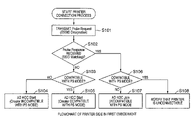
- FIG. 7 is a flowchart showing an operation of the printer 302 according to the first embodiment
- FIG. 8 is a flowchart showing an operation of the DSC 301 according to the first embodiment
- FIG. 9 is a view showing an example of the first three bytes of a MAC address
- FIG. 10 is a view showing a Management frame format
- FIG. 11 is a flowchart showing an operation of a printer 302 according to the second embodiment
- FIG. 12 is a flowchart showing an operation of a DSC 301 according to the second embodiment.
- FIG. 13 is a timing chart showing a PS mode in an ad hoc mode.
- FIG. 1 is a schematic view showing a wireless communication system according to the first embodiment of the present invention.
- a digital still camera (to be referred to as a DSC hereinafter) 301 which has a wireless communication function.
- the DSC 301 can transfer data to a printer, personal computer, and the like via a wireless communication device.
- a printer 302 is also provided which has the same wireless communication function.
- the DSC 301 and printer 302 are wirelessly connected with each other in the ad hoc mode based on IEEE802.11 standard. Accordingly, image data sensed by the DSC 301 is wirelessly transmitted to the printer 302 , and output at the printer 302 .
- FIG. 2 is a functional block diagram showing an arrangement of the DSC 301 .
- the DSC 301 includes an image sensing unit 402 , image sensing processing unit 403 , wireless communication function unit 404 , RF (Radio Frequency) unit 405 , display unit 406 , display processing unit 407 , memory card interface (I/F) 408 , memory card 409 , operation unit 410 , system controller 411 , USB interface (I/F) 412 , flash ROM 413 , audio interface (I/F) 414 , CPU 415 , ROM 416 , and RAM 417 .
- I/F Radio Frequency
- the operation unit 410 is connected to the CPU 415 via a system controller 411 , and includes, e.g., the shutter switch and various keys of the DSC 301 .
- An image sensing unit 402 is a block which senses an image when the shutter is pressed, and controlled by the image sensing processing unit 403 .
- the display unit 406 is a block which displays information to a user (e.g., LCD display, LED display, and audio indication).
- the display contents of the display unit 406 are controlled by the display processing unit 407 .
- An operation such as selection of an instruction in accordance with information displayed on the display unit 406 is performed in synchronism with the operation unit 410 . That is, the display unit 406 and operation unit 410 mainly construct the user interface (I/F) of the DSC 301 .
- the wireless communication function unit 404 is a block to perform wireless communication, and the RF unit 405 transmits/receives a radio signal to/from another wireless communication device.
- the memory card I/F 408 is used to connect the memory card 409
- the USB I/F 412 is used to connect an external device via a USB
- the audio I/F 414 is used to exchange an audio signal with an external device.
- the flash ROM 413 is a nonvolatile storage area. In the flash ROM 413 , wireless communication setting information and the like are stored. Note that sensed image data is written (saved) in the memory card 409 via the memory card I/F 408 after a well-known compression process.
- FIG. 3 is a functional block diagram showing an arrangement of the printer 302 .
- the printer 302 includes a print engine 502 , print processing unit 503 , wireless communication function unit 504 , RF unit 505 , display unit 506 , display processing unit 507 , memory card I/F 508 , memory card 509 , operation unit 510 , system controller 511 , USB I/F 512 , flash ROM 513 , parallel I/F 514 , CPU 515 , ROM 516 , and RAM 517 .
- the operation unit 510 is connected to the CPU 515 via the system controller 511 .
- the print engine 502 is a functional block which actually prints an image on paper, and controlled by the printing process unit 503 .
- the printing method performed by the print engine 502 is arbitrary. For example, an inkjet printer which discharges ink droplets by thermal energy onto a printing medium such as a printing sheet is available.
- the display unit 506 is a block which displays information to the user (e.g., LCD display, LED display, and audio indication), and the display contents of the display unit 506 are controlled by the display processing unit 507 .
- An operation such as selection of an instruction in accordance with information displayed on the display unit 506 is performed via the operation unit 510 . That is, the display unit 506 and operation unit 510 mainly construct a user I/F of the printer 302 .
- the wireless communication function unit 504 is a block to perform wireless communication, and the RF unit 505 transmits/receives the radio signal to/from another wireless communication device.
- the memory card I/F 508 is used to connect the detachable memory card 509 .
- a memory card which was mounted in the DSC 301 is inserted into the memory card I/F 508 , and then a sensed image can be printed.
- the USB I/F 512 is used to connect an external device via a USB
- the parallel I/F 514 is used to connect the external device (mainly, host computer) using parallel communication.
- the flash ROM 513 is a nonvolatile storage area, and wireless communication setting information and the like are stored in the flash ROM 513 .
- FIG. 4 is a view showing parameters in detail.
- eight parameters are provided to establish wireless connection, i.e., “Network Mode”, “SSID Type”, “CH Number”, “Authentication Type”, “Encryption Type”, “Encryption Key”, “Device ID”, and “Ad hoc PS”. According to the first embodiment, these parameters are set in the DSC 301 in advance, and then transferred to the printer 302 (to be described later).
- Network Mode is an item for designating whether a network creation method is in an “Infrastructure” or “Ad hoc” mode. In the following description, assume that the network creation method is in the “Ad hoc” mode.
- the parameter “SSID Type” is an item for designating an “ESS ID” serving as a network identifier.
- the value of this item is automatically calculated and set using a specific algorithm on the basis of a device fixed value such as the serial number of the DSC 301 . Therefore, since this value is represented by random alphanumeric characters, the value cannot be artificially set.
- the same ESS ID is not set for another DSC.
- the value of the parameter “SSID Type” cannot be rewritten unless the parameter is exceptionally rewritten via wired connection such as a USB with the personal computer or the like. In the following description, assume that the value of the parameter “SSID Type” is not rewritten.
- the parameter “CH Number” is an item for designating a frequency channel to be used. This item is used only when the network is created in the ad hoc mode.
- the parameter “Authentication Type” is an item for designating an authentication method which is applied in the network. More specifically, the user selects an “Open System” or “Shared System”.
- the parameter “Encryption Type” is an item for designating an encryption method which is applied in the network. More specifically, the user selects a “WEP (40 bits)”, “WEP (104 bits)”, or “WPA-PSK”.
- Encryption Key is an item for designating a key used to perform encryption. Its key length changes due to variations in encryption means, and set by user's direct input.
- the parameter “Device ID” is an identifier allocated to each device, and unique to the device. For example, on the basis of this identifier, it can be identified whether the device is the DSC 301 or printer 302 . Also, on the basis of this identifier, a manufacturer and the like can be identified. For example, this value is set when shipping from a factory, and cannot be rewritten after that.
- the parameter “Ad hoc PS” is an item for deciding the presence/absence of a PS mode operation in the ad hoc mode, and set by the user. If this item is “ON”, the device operates in the PS mode of the ad hoc mode. If this item is “OFF”, the terminal does not operate in the PS mode. Note that in the device without a PS mode function in the ad hoc mode, this parameter is always set “OFF”, and cannot be rewritten to “ON”.
- the personal computer is not present in the wireless communication system.
- the parameter of the DSC 301 or printer 302 cannot be set by the PC.
- the printer 302 does not have the user interface (UI) for setting the parameter in detail as shown in FIG. 4 , because a versatile printer is assumed to be used. Therefore, as described above, parameter setting shown in FIG. 4 is performed in the DSC 301 having a more advanced UI than that of the printer 302 .
- the value set by the DSC 301 is reflected on that of the printer 302 .
- a wireless communication parameter set in the DSC 301 is stored in the flash ROM 413 .
- FIG. 5 is a schematic view showing a parameter setting method
- FIG. 6 is a sequence chart showing parameter setting.
- step S 1001 an initial setting operation is started by pressing a power button while pressing a reset button, or pressing an “initialization start button” which has been set in advance.
- the DSC 301 Upon starting the initial setting operation, the DSC 301 transmits, via the USB I/F 412 , a request command “wireless function confirmation request” for confirming whether the printer 302 has the wireless communication device (step S 1002 ). For example, in accordance with this request contents, the printer 302 confirms whether predetermined information (information indicating the presence of the wireless communication function) is stored on the flash ROM 513 or ROM 516 of the printer 302 .
- the printer 302 comprises the wireless communication device (wireless communication function unit 504 , RF unit 505 , and the like).
- the printer 302 upon reception of the “wireless function confirmation request”, the printer 302 issues a response as a “wireless function confirmation acknowledgement” indicating that the printer 302 has the wireless communication function, to the DSC 301 via the USB I/F 512 (step S 1003 ).
- the printer issues no response to the DSC 301 after a predetermined period of time has elapsed from transmission of the “wireless function confirmation request”, it is determined that the connected device (printer 302 ) is incompatible with at least the wireless direct print, and the process ends.
- the DSC 301 Upon reception of the “wireless function confirmation acknowledgement”, the DSC 301 can analyze the response contents, and obtain information indicating that the printer 302 comprises the wireless communication device.
- the printer 302 when the printer 302 is incompatible with the PS mode function in the ad hoc mode although the parameter “Ad hoc PS” of the DSC 301 is set “ON”, mismatching occurs. In this case, upon reception of the “wireless function confirmation request”, the printer 302 notifies the DSC 301 in the “wireless function confirmation acknowledgement” that the parameter “Ad hoc PS” cannot be set “ON” because the printer 302 is incompatible with the PS mode function in the ad hoc mode.
- the DSC 301 Upon reception of this response, the DSC 301 notifies the user via the display unit 506 or the like that the parameter “Ad hoc PS” cannot be set “ON”, and that this connection cannot be made unless the parameter “Ad hoc PS” is set “OFF”. If the user wants to make this connection even by changing the parameter “Ad hoc PS” to “OFF”, the process may be continued by setting the parameter “Ad hoc PS” “OFF”. Alternatively, when the user does not want to make this connection, a USB cable is disconnected, and the process is interrupted.
- the DSC 301 After analyzing the “wireless function confirmation acknowledgement”, the DSC 301 transmits, via the USB I/F 412 , a “wireless communication information update request” for confirming update of the wireless communication parameter in the printer 302 (step S 1004 ). For example, in accordance with this request contents, the user of the printer 302 confirms whether the wireless setting information of the DSC 301 is set or updated to the flash ROM 513 of the printer 302 .
- the printer 302 Upon reception of the “wireless communication information update request”, after user's confirmation, the printer 302 permits to write data on the flash ROM 513 in order to establish and implement the wireless communication with the DSC 301 . After that, the printer 302 issues a response as the “wireless communication information update acknowledgement” indicating that permission, to the DSC 301 via the USB I/F 512 (step S 1005 ).
- the DSC 301 Upon reception of the “wireless communication information update acknowledgement”, in order to set the wireless communication setting information shown in FIG. 4 , the DSC 301 transmits the “wireless communication information setting request” with the wireless communication setting information as a parameter, to the printer 302 via the USB I/F 412 (step S 1006 ). For example, in accordance with this request contents, the wireless communication setting information transmitted as the parameter to the flash ROM 513 of the printer is stored in the printer 302 .
- the printer 302 Upon reception of the “wireless communication information setting request”, the printer 302 stores the wireless communication setting information in the flash ROM 513 . The printer 302 then issues a response as the “wireless communication information setting acknowledgement” indicating the setting completion, to the DSC 301 via the USB I/F 512 (step S 1007 ).
- the DSC 301 which supports the USB or wireless communication is once wired-connected to the printer 302 , the DSC 301 and printer 302 can share the information required for wireless communication.
- the USB cable 903 can be disconnected.
- the printer 302 can be searched for on the basis of the obtained wireless communication setting information, and wirelessly connect to the DSC 301 (step S 1008 ).
- the power of the wireless communication function unit in the DSC 301 is turned off to start a connection process of the printer 302 .
- the process will be described in detail with reference to FIG. 7 .
- step S 101 information which is notified by the DSC 301 via wired communication and required for wireless communication is set.
- a scanning process active scan
- a “Probe Request” is transmitted by broadcast
- a “Probe Response” received as a response is analyzed, and a wireless space state can be searched for.
- the frame formats of the “Probe Request” and “Probe Response” are made in a Management frame format as shown in FIG. 10 .
- control information such as a MAC protocol version based on IEEE802.11 standard and the like is stored.
- Duration for example, a parameter used for a carrier sense and the like is stored.
- a “BSSID (Basic Service Set IDentification)” field is an arbitrary value which includes 48 bytes for identifying the network.
- a “Sequence Control” field the sequence number of a MAC frame and a fragment number for a fragment are stored.
- a “Frame Body” field detailed data pertaining to the “Probe Request”, “Probe Response”, and “Beacon” are stored.
- FCS error detection codes of a MAC header and the “Frame Body” are stored.
- DA transmission destination address is stored.
- SA transmission source address is stored.
- step S 101 when the printer 302 receives the “Probe Response” having the same value as the ESS ID set in the printer 302 (step S 102 ), the printer 302 recognizes that the network to be created by the printer 302 has already run. That is, the printer 302 recognizes that the network is created by a device other than the DSC 301 . If the parameter “Ad hoc PS” in the wireless setting item in FIG. 4 is “OFF” (step S 106 ), the printer 302 incompatible with the PS mode joins the network (step S 107 ).
- the printer 302 notifies the user that the printer 302 cannot connect to the network, and the process ends without joining the network (step S 108 ).
- the user reconfirms and resets the wireless setting items.
- the parameter “Ad hoc PS” is set “ON”.
- the process ends (steps S 106 and S 108 ).
- step S 101 when the “Probe Response” having the same value of the ESS ID set in the printer 302 cannot be received (step S 102 ), the printer 302 recognizes that the network to be created by the printer 302 is not present.
- the printer 302 then creates the network in accordance with the wireless communication items shown in FIG. 4 , i.e., the network compatible with the PS mode of the ad hoc mode (step S 105 ). More specifically, the printer 302 starts transmitting the “Beacon” by setting “ATIM window value ⁇ 0” in the “Beacon”.
- the printer 302 transmits the “Beacon” by setting “ATIM window value ⁇ 0” in the “Beacon”, and the network incompatible with the PS mode is created (step S 104 ).
- a wireless network joining process of the DSC 301 is started. The process will be described in detail with reference to FIG. 8 .
- the scanning process (active scan) is also started as in the process in the printer 302 (step S 201 ).
- the detailed process is the same as that of the printer 302 .
- step S 201 when the DSC 301 does not receive the “Probe Response” having the same value as the ESS ID set in the DSC 301 (step S 202 ), the network which the DSC 301 is to join is not present. That is, it is determined that the wireless communication function is invalid since the power of the printer 302 is OFF, or that the wireless setting item is incorrectly set.
- the DSC 301 prompts the user to confirm the power of the printer 302 and reconfirm the wireless setting item (step S 203 ) in place of issuing the “Beacon” from the DSC 301 itself, and then the scanning process is performed again (step S 201 ).
- step S 201 when the DSC 301 receives the “Probe Response” having the same value as the ESS ID set in the DSC 301 , the DSC 301 analyzes the MAC address included in the “Probe Response” (step S 204 ).
- the MAC address is stored in the “SA” field in the Management frame format as shown in FIG. 10 .
- the MAC address is constituted by 48 bits (6 bytes).
- the vender codes of IEEE network devices are allocated to the first three bytes of this MAC address.
- a network vender allocates the unique numbers of its products to the remaining three bytes.
- the DSC 301 registers the first three bytes of the MAC address indicating the device vender which guarantees the PS mode operation in the ad hoc mode, in the ROM 416 and the like as a list shown in FIG. 9 .
- step S 204 the first three bytes of the MAC address obtained by the “Probe Response” are compared with the list. As a result of comparison, when the first three bytes of the MAC address are held in the list, it is determined that the device serving as a transmission source of the “Probe Response” is a device which guarantees the PS mode operation in the ad hoc mode.
- step S 204 when the first three bytes of the MAC address are not held in the list shown in FIG. 9 , the PS mode operation is not guaranteed. Hence, the DSC 301 incompatible with the PS mode joins the network (step S 107 ).
- the first three bytes of the MAC address may be included in the parameter “Device ID” of the wireless communication setting information shown in FIG. 4 in place of obtaining the first three bytes of the MAC address from the “Probe Response”.
- the first three bytes of the MAC address can be notified between the DSC 301 and the printer 302 by using the “wireless function confirmation request” (step S 1002 ), “wireless function confirmation acknowledgement” (step S 1003 ), “wireless communication information update request” (step S 1004 ), and “wireless communication information update acknowledgement” (step S 1005 ).
- step S 204 when the first three bytes of the MAC address are held in the list shown in FIG. 9 , the parameter “Ad hoc PS” of the wireless communication item shown in FIG. 4 is confirmed in the DSC 301 (step S 205 ).
- the DSC 301 joins the network in the PS mode (step S 206 ).
- the DSC 301 incompatible with the PS mode joins the network (step S 207 ).
- the wireless communication setting information is commonly set between the printer 302 and the DSC 301 .
- the wireless communication setting information By using the wireless communication setting information, the ad hoc mode wireless network is created between the printer 302 and the DSC 301 .
- the printer 302 and DSC 301 operate in the PS mode, data transmission in the network is guaranteed. Therefore, the image sensed by the DSC 301 can be reliably output to the printer 302 while power consumption is reduced.
- the DSC 301 detects the power-off state of the printer 302 , and the powers of at least the wireless communication function unit 404 and RF unit 405 are also turned off. This is because if the powers of at least the wireless communication function unit 404 and RF unit 405 are ON in the DSC 301 , the DSC 301 issues the “Probe Response” including the ESS ID set in the printer 302 when the power of the printer 302 is turned on again and the scanning process is executed, thus posing a problem.
- a state confirmation signal may be periodically transmitted from the DSC 301 to the printer 302 to wait for the response. It may be determined that the power of the printer 302 is turned off when no response is received. Alternatively, the “Beacon” transmitted from the printer 302 may be always monitored. It may be determined that the power of the printer 302 is turned off when the “Beacon” is not detected.
- the wireless space state is checked by the “active scan scheme” of transmitting the “Probe Request” and receiving the “Probe Response”.
- the wireless space state is checked by a “passive scan scheme”. Note that the system arrangement of a wireless communication system is the same as that of the first embodiment shown in FIG. 1 .
- a preparation sequence of creating a wireless network in a PS mode in an ad hoc mode by using a DSC 301 and printer 302 is also the same as that of the first embodiment.
- the power of a wireless communication function unit in the DSC 301 is turned off, and a connection process of the printer 302 is started. Details of this process will be described below with reference to FIG. 11 .
- step S 1201 information which is notified by the DSC 301 and required for wireless communication is set to start a scanning process (passive scan) (step S 1201 ). More specifically, all “Beacon” frames in the wireless space are received and analyzed to check the wireless space state.
- a “Beacon” frame format is formed in a Management frame format shown in FIG. 10 . Field contents included in this frame are the same as those of the first embodiment.
- step S 1201 when the printer 302 receives a “Beacon” having the same value as an ESS ID set in the printer 302 (step S 1202 ), the printer 302 recognizes that the network to be created by the printer 302 has already run. That is, the printer 302 recognizes that the network is created by a device other than the DSC 301 . If a parameter “Ad hoc PS” in a wireless setting item in FIG. 4 is “OFF” in the printer 302 (step S 1206 ), the printer 302 incompatible with the PS mode joins the network (step S 1207 ).
- the printer 302 notifies a user that the printer 302 cannot connect to the network, and the process ends without joining the network (step S 1208 ).
- the process ends (steps S 1206 and S 1208 ).
- step S 101 when the “Beacon” having the same value of the ESS ID set in the printer 302 cannot be received (step S 1202 ), the printer 302 recognizes that the network to be created by the printer 302 is not present.
- the printer 302 then creates the network in accordance with the wireless communication items shown in FIG. 4 , i.e., the network compatible with the PS mode of the ad hoc mode (step S 1205 ). More specifically, the printer 302 starts transmitting the “Beacon” by setting “ATIM window value ⁇ 0” in the “Beacon”.
- the printer 302 transmits the “Beacon” by setting “ATIM window value ⁇ 0” in the “Beacon”, and the network incompatible with the PS mode is created (step S 1204 ).
- a wireless network joining process of the DSC 301 is started. The process will be described in detail with reference to FIG. 12 .
- the scanning process (passive scan) is also started as in the process in the printer 302 (step S 1301 ).
- the detailed process is the same as that of the printer 302 .
- step S 1301 when the DSC 301 does not receive the “Beacon” having the same value as the ESS ID set in the DSC 301 (step S 1302 ), the network which the DSC 301 is to join is not present. That is, it is determined that the wireless communication function is invalid since the power of the printer 302 is OFF, or that the wireless setting item is incorrectly set.
- the DSC 301 prompts the user to confirm the power of the printer 302 and reconfirm the wireless setting item (step S 1303 ), and then the scanning process is performed again (step S 1301 ).
- step S 1301 when the DSC 301 receives the “Beacon” having the same value as the ESS ID set in the DSC 301 , the DSC 301 analyzes the MAC address included in the “Beacon”, and performs a comparison process as in the first embodiment (step S 1304 ). That is, the first three bytes of the MAC address obtained from the “Beacon” are compared with a list shown in FIG. 9 , and it is confirmed whether the device serving as a transmission source of the “Beacon” is a device which guarantees the PS mode operation in the ad hoc mode.
- step S 1304 when the first three bytes of the MAC address are not held in the list shown in FIG. 9 , the PS mode operation is not guaranteed. Hence, the DSC 301 incompatible with the PS mode joins the network (step S 1307 ).
- step S 1304 when the first three bytes of the MAC address are held in the list shown in FIG. 9 , the parameter “Ad hoc PS” of the wireless communication item shown in FIG. 4 is confirmed (step S 1305 ).
- the DSC 301 joins the network in the PS mode (step S 1306 ).
- the DSC 301 incompatible with the PS mode joins the network (step S 1307 ).
- the wireless communication setting information is commonly set between the printer 302 and the DSC 301 .
- the wireless communication setting information By using the wireless communication setting information, the ad hoc mode wireless network is created between the printer 302 and the DSC 301 .
- the printer 302 and DSC 301 operate in the PS mode, data transmission in the network is guaranteed. Therefore, the image sensed by the DSC 301 can be reliably output to the printer 302 while power consumption is reduced.
- the powers of at least the wireless communication function unit 404 and RF unit 405 must also be turned off. This process is the same as that of the first embodiment.
- the present invention can be applied to an apparatus comprising a single device or to system constituted by a plurality of devices.
- the invention can be implemented by supplying a software program, which implements the functions of the foregoing embodiments, directly or indirectly to a system or apparatus, reading the supplied program code with a computer of the system or apparatus, and then executing the program code.
- a software program which implements the functions of the foregoing embodiments
- reading the supplied program code with a computer of the system or apparatus, and then executing the program code.
- the mode of implementation need not rely upon a program.
- the program code installed in the computer also implements the present invention.
- the claims of the present invention also cover a computer program for the purpose of implementing the functions of the present invention.
- the program may be executed in any form, such as an object code, a program executed by an interpreter, or scrip data supplied to an operating system.
- Example of storage media that can be used for supplying the program are a floppy disk, a hard disk, an optical disk, a magneto-optical disk, a CD-ROM, a CD-R, a CD-RW, a magnetic tape, a non-volatile type memory card, a ROM, and a DVD (DVD-ROM and a DVD-R).
- a client computer can be connected to a website on the Internet using a browser of the client computer, and the computer program of the present invention or an automatically-installable compressed file of the program can be downloaded to a recording medium such as a hard disk.
- the program of the present invention can be supplied by dividing the program code constituting the program into a plurality of files and downloading the files from different websites.
- a WWW World Wide Web
- a storage medium such as a CD-ROM
- an operating system or the like running on the computer may perform all or a part of the actual processing so that the functions of the foregoing embodiments can be implemented by this processing.
- a CPU or the like mounted on the function expansion board or function expansion unit performs all or a part of the actual processing so that the functions of the foregoing embodiments can be implemented by this processing.
Landscapes
- Engineering & Computer Science (AREA)
- Computer Networks & Wireless Communication (AREA)
- Signal Processing (AREA)
- Mobile Radio Communication Systems (AREA)
- Small-Scale Networks (AREA)
Priority Applications (2)
| Application Number | Priority Date | Filing Date | Title |
|---|---|---|---|
| US12/257,122 US8576813B2 (en) | 2004-11-05 | 2008-10-23 | Communication system, communication apparatus, and communication method |
| US14/050,650 US20140036753A1 (en) | 2004-11-05 | 2013-10-10 | Communication system, communication apparatus, and communication method |
Applications Claiming Priority (2)
| Application Number | Priority Date | Filing Date | Title |
|---|---|---|---|
| JP2004322325A JP4438063B2 (ja) | 2004-11-05 | 2004-11-05 | 通信システム、通信装置、通信方法、及びプログラム |
| JP2004-322325 | 2004-11-05 |
Related Child Applications (1)
| Application Number | Title | Priority Date | Filing Date |
|---|---|---|---|
| US12/257,122 Division US8576813B2 (en) | 2004-11-05 | 2008-10-23 | Communication system, communication apparatus, and communication method |
Publications (2)
| Publication Number | Publication Date |
|---|---|
| US20060120313A1 US20060120313A1 (en) | 2006-06-08 |
| US7489669B2 true US7489669B2 (en) | 2009-02-10 |
Family
ID=36574089
Family Applications (3)
| Application Number | Title | Priority Date | Filing Date |
|---|---|---|---|
| US11/267,556 Expired - Fee Related US7489669B2 (en) | 2004-11-05 | 2005-11-04 | Communication system, communication apparatus and communication method |
| US12/257,122 Expired - Fee Related US8576813B2 (en) | 2004-11-05 | 2008-10-23 | Communication system, communication apparatus, and communication method |
| US14/050,650 Abandoned US20140036753A1 (en) | 2004-11-05 | 2013-10-10 | Communication system, communication apparatus, and communication method |
Family Applications After (2)
| Application Number | Title | Priority Date | Filing Date |
|---|---|---|---|
| US12/257,122 Expired - Fee Related US8576813B2 (en) | 2004-11-05 | 2008-10-23 | Communication system, communication apparatus, and communication method |
| US14/050,650 Abandoned US20140036753A1 (en) | 2004-11-05 | 2013-10-10 | Communication system, communication apparatus, and communication method |
Country Status (2)
| Country | Link |
|---|---|
| US (3) | US7489669B2 (enExample) |
| JP (1) | JP4438063B2 (enExample) |
Cited By (3)
| Publication number | Priority date | Publication date | Assignee | Title |
|---|---|---|---|---|
| US20090029647A1 (en) * | 2005-12-05 | 2009-01-29 | Lenovo (Beijing) Limited | Wireless display system and method thereof |
| US20100254290A1 (en) * | 2009-04-07 | 2010-10-07 | Gong Michelle X | Device power management in a wireless network |
| US20130201871A1 (en) * | 2007-05-29 | 2013-08-08 | Canon Kabushiki Kaisha | Wireless communication apparatus and control method therefor |
Families Citing this family (25)
| Publication number | Priority date | Publication date | Assignee | Title |
|---|---|---|---|---|
| JP4387925B2 (ja) * | 2004-11-04 | 2009-12-24 | キヤノン株式会社 | 通信装置、制御方法及びそのプログラム |
| US20060253735A1 (en) * | 2005-03-11 | 2006-11-09 | Interdigital Technology Corporation | Method and system for conserving battery power of mesh points in a mesh network |
| JP4921064B2 (ja) * | 2006-07-31 | 2012-04-18 | キヤノン株式会社 | 通信装置、通信方法、通信装置を制御するためのプログラム及びプログラムを格納した記憶媒体 |
| JP4886463B2 (ja) * | 2006-10-20 | 2012-02-29 | キヤノン株式会社 | 通信パラメータ設定方法、通信装置及び通信パラメータを管理する管理装置 |
| JP4789817B2 (ja) * | 2007-01-29 | 2011-10-12 | キヤノン株式会社 | 通信装置及び通信装置の通信方法、プログラム |
| EP2109960B1 (en) | 2007-02-13 | 2018-01-03 | SK Telecom. Co., Ltd. | Method for allocating a beacon slot using a beacon table in wireless personal area network (wpan) and wpan device |
| TW200846891A (en) * | 2007-05-21 | 2008-12-01 | Dfi Inc | Method for resetting basic input output system |
| JP5235342B2 (ja) * | 2007-06-22 | 2013-07-10 | キヤノン株式会社 | 通信装置、制御方法及びプログラム |
| US8108777B2 (en) * | 2008-08-11 | 2012-01-31 | Microsoft Corporation | Sections of a presentation having user-definable properties |
| JP2011109252A (ja) * | 2009-11-13 | 2011-06-02 | Canon Inc | 通信装置、通信装置の制御方法およびプログラム |
| JP5957935B2 (ja) * | 2012-02-14 | 2016-07-27 | セイコーエプソン株式会社 | 制御装置、制御装置の制御方法、及び、プログラム |
| JP5962896B2 (ja) | 2012-03-26 | 2016-08-03 | ブラザー工業株式会社 | プリンタ |
| JP6128813B2 (ja) * | 2012-11-29 | 2017-05-17 | キヤノン株式会社 | 印刷装置、印刷装置の制御方法、及びプログラム |
| JP6128844B2 (ja) * | 2012-12-28 | 2017-05-17 | キヤノン株式会社 | 通信装置およびその制御方法、プログラム並びに記憶媒体 |
| JP6242051B2 (ja) * | 2013-01-23 | 2017-12-06 | キヤノン株式会社 | 通信装置、通信装置の制御方法、プログラム |
| JP5838988B2 (ja) * | 2013-03-28 | 2016-01-06 | ブラザー工業株式会社 | 通信プログラムおよび通信装置 |
| JP5962564B2 (ja) | 2013-03-28 | 2016-08-03 | ブラザー工業株式会社 | 通信制御プログラムおよび通信装置 |
| US9560535B2 (en) * | 2013-10-03 | 2017-01-31 | Sercomm Corporation | Data stream generation and transmission system and method therefor |
| JP5980258B2 (ja) * | 2014-03-11 | 2016-08-31 | キヤノン株式会社 | 情報処理装置、情報処理装置の制御方法及びプログラム |
| JP6340917B2 (ja) * | 2014-05-23 | 2018-06-13 | 富士ゼロックス株式会社 | 文書管理プログラム、文書閲覧編集プログラム、文書管理装置、端末装置及び文書管理システム |
| JP6512798B2 (ja) * | 2014-11-19 | 2019-05-15 | キヤノン株式会社 | 通信装置、制御方法、及びプログラム |
| US20160183187A1 (en) * | 2014-12-22 | 2016-06-23 | Intel Corporation | Adjacent channel interference mitigation for low-power wake-up radio |
| JP6516491B2 (ja) * | 2015-01-30 | 2019-05-22 | キヤノン株式会社 | 通信装置、制御方法およびプログラム |
| JP6724338B2 (ja) * | 2015-10-30 | 2020-07-15 | ブラザー工業株式会社 | 通信機器 |
| US20170294765A1 (en) * | 2016-04-06 | 2017-10-12 | Warren Stanley King | Wire clearance apparatus and method |
Citations (3)
| Publication number | Priority date | Publication date | Assignee | Title |
|---|---|---|---|---|
| JPH09135254A (ja) | 1995-11-08 | 1997-05-20 | Nec Corp | ローカルエリアネットワークの省電力制御システム |
| US20040125778A1 (en) * | 2002-12-26 | 2004-07-01 | Newsoft Technology Corporation | Method and system for improving transmission efficiency of wireless local area network |
| US20040205158A1 (en) * | 2003-02-24 | 2004-10-14 | Hsu Raymond T. | Wireless local access network system detection and selection |
Family Cites Families (6)
| Publication number | Priority date | Publication date | Assignee | Title |
|---|---|---|---|---|
| JP2003022351A (ja) | 2001-07-09 | 2003-01-24 | Toshiba Corp | 人事情報管理システム、プログラムおよび人事情報管理方法 |
| JP4458720B2 (ja) | 2001-08-29 | 2010-04-28 | 株式会社リコー | 画像入力装置およびプログラム |
| US20030235309A1 (en) * | 2002-03-08 | 2003-12-25 | Marinus Struik | Local area network |
| JP2004213548A (ja) | 2003-01-08 | 2004-07-29 | Sony Corp | 情報処理装置および方法、並びにプログラム |
| US7468969B2 (en) * | 2003-11-07 | 2008-12-23 | Interdigital Technology Corporation | Apparatus and methods for central control of mesh networks |
| JP5196716B2 (ja) * | 2005-09-13 | 2013-05-15 | キヤノン株式会社 | 無線通信装置及びプログラム |
-
2004
- 2004-11-05 JP JP2004322325A patent/JP4438063B2/ja not_active Expired - Fee Related
-
2005
- 2005-11-04 US US11/267,556 patent/US7489669B2/en not_active Expired - Fee Related
-
2008
- 2008-10-23 US US12/257,122 patent/US8576813B2/en not_active Expired - Fee Related
-
2013
- 2013-10-10 US US14/050,650 patent/US20140036753A1/en not_active Abandoned
Patent Citations (3)
| Publication number | Priority date | Publication date | Assignee | Title |
|---|---|---|---|---|
| JPH09135254A (ja) | 1995-11-08 | 1997-05-20 | Nec Corp | ローカルエリアネットワークの省電力制御システム |
| US20040125778A1 (en) * | 2002-12-26 | 2004-07-01 | Newsoft Technology Corporation | Method and system for improving transmission efficiency of wireless local area network |
| US20040205158A1 (en) * | 2003-02-24 | 2004-10-14 | Hsu Raymond T. | Wireless local access network system detection and selection |
Cited By (7)
| Publication number | Priority date | Publication date | Assignee | Title |
|---|---|---|---|---|
| US20090029647A1 (en) * | 2005-12-05 | 2009-01-29 | Lenovo (Beijing) Limited | Wireless display system and method thereof |
| US8213858B2 (en) * | 2005-12-05 | 2012-07-03 | Lenovo (Beijing) Limited | Wireless display system and method thereof |
| US20130201871A1 (en) * | 2007-05-29 | 2013-08-08 | Canon Kabushiki Kaisha | Wireless communication apparatus and control method therefor |
| US8804683B2 (en) * | 2007-05-29 | 2014-08-12 | Canon Kabushiki Kaisha | Wireless communication apparatus and control method therefor |
| US20140267813A1 (en) * | 2007-05-29 | 2014-09-18 | Canon Kabushiki Kaisha | Wireless communication apparatus and control method therefor |
| US8976772B2 (en) * | 2007-05-29 | 2015-03-10 | Canon Kabushiki Kaisha | Wireless communication apparatus and control method therefor |
| US20100254290A1 (en) * | 2009-04-07 | 2010-10-07 | Gong Michelle X | Device power management in a wireless network |
Also Published As
| Publication number | Publication date |
|---|---|
| US8576813B2 (en) | 2013-11-05 |
| US20090092068A1 (en) | 2009-04-09 |
| US20140036753A1 (en) | 2014-02-06 |
| JP2006135654A (ja) | 2006-05-25 |
| JP4438063B2 (ja) | 2010-03-24 |
| US20060120313A1 (en) | 2006-06-08 |
Similar Documents
| Publication | Publication Date | Title |
|---|---|---|
| US8576813B2 (en) | Communication system, communication apparatus, and communication method | |
| US11902869B2 (en) | Communication device | |
| US7554979B2 (en) | Communication apparatus and method having function of transmitting notification signal while hiding group identification information | |
| EP1738529B1 (en) | A communication control method and wireless communication apparatus | |
| US8103003B2 (en) | Method for setting communication parameters and communication device | |
| US9444874B2 (en) | Automatic Ad-Hoc network creation and coalescing using WPS | |
| US10645630B2 (en) | Communication apparatus, method and system | |
| US20100146129A1 (en) | Communication apparatus and method for wi-fi protected setup in adhoc network | |
| US20120282860A1 (en) | Communication system and method, information processing apparatus and method, information processing terminal and method | |
| US20150126115A1 (en) | Method of registering use of mobile terminal to image forming apparatus, the image forming apparatus using the method, method of requesting registration of use of the mobile terminal, and the mobile terminal using the method | |
| US7623480B2 (en) | Communication apparatus, control method, and program therefor | |
| CN110611904B (zh) | 控制方法、信息处理设备和非暂时性计算机可读存储介质 | |
| JP4632430B2 (ja) | 無線通信装置および無線通信装置の制御方法、並びに、プログラム | |
| JP4777229B2 (ja) | 通信システム、管理装置、管理装置の制御方法、及び当該制御方法をコンピュータに実行させるためのコンピュータプログラム | |
| JP5147799B2 (ja) | 通信システム、通信装置、通信方法、及びプログラム | |
| US20230091461A1 (en) | Information processing apparatus, communication apparatus, control method therefor, and storage medium |
Legal Events
| Date | Code | Title | Description |
|---|---|---|---|
| AS | Assignment |
Owner name: CANON KABUSHIKI KIASHA, JAPAN Free format text: ASSIGNMENT OF ASSIGNORS INTEREST;ASSIGNORS:MORITOMO, KAZUO;YOKOTA, AKANE;REEL/FRAME:017272/0121 Effective date: 20051025 |
|
| FEPP | Fee payment procedure |
Free format text: PAYOR NUMBER ASSIGNED (ORIGINAL EVENT CODE: ASPN); ENTITY STATUS OF PATENT OWNER: LARGE ENTITY |
|
| FPAY | Fee payment |
Year of fee payment: 4 |
|
| REMI | Maintenance fee reminder mailed | ||
| LAPS | Lapse for failure to pay maintenance fees | ||
| STCH | Information on status: patent discontinuation |
Free format text: PATENT EXPIRED DUE TO NONPAYMENT OF MAINTENANCE FEES UNDER 37 CFR 1.362 |
|
| FP | Lapsed due to failure to pay maintenance fee |
Effective date: 20170210 |