US7396154B2 - Regulating element for wristwatch and mechanical movement comprising one such regulating element - Google Patents
Regulating element for wristwatch and mechanical movement comprising one such regulating element Download PDFInfo
- Publication number
- US7396154B2 US7396154B2 US11/789,817 US78981707A US7396154B2 US 7396154 B2 US7396154 B2 US 7396154B2 US 78981707 A US78981707 A US 78981707A US 7396154 B2 US7396154 B2 US 7396154B2
- Authority
- US
- United States
- Prior art keywords
- balance
- regulating member
- magnets
- mobile
- magnet
- Prior art date
- Legal status (The legal status is an assumption and is not a legal conclusion. Google has not performed a legal analysis and makes no representation as to the accuracy of the status listed.)
- Active
Links
Images


Classifications
-
- G—PHYSICS
- G04—HOROLOGY
- G04C—ELECTROMECHANICAL CLOCKS OR WATCHES
- G04C3/00—Electromechanical clocks or watches independent of other time-pieces and in which the movement is maintained by electric means
- G04C3/04—Electromechanical clocks or watches independent of other time-pieces and in which the movement is maintained by electric means wherein movement is regulated by a balance
- G04C3/06—Electromechanical clocks or watches independent of other time-pieces and in which the movement is maintained by electric means wherein movement is regulated by a balance using electromagnetic coupling between electric power source and balance
- G04C3/065—Electromechanical clocks or watches independent of other time-pieces and in which the movement is maintained by electric means wherein movement is regulated by a balance using electromagnetic coupling between electric power source and balance the balance controlling gear-train by means of static switches, e.g. transistor circuits
- G04C3/066—Constructional details, e.g. disposition of coils
-
- G—PHYSICS
- G04—HOROLOGY
- G04B—MECHANICALLY-DRIVEN CLOCKS OR WATCHES; MECHANICAL PARTS OF CLOCKS OR WATCHES IN GENERAL; TIME PIECES USING THE POSITION OF THE SUN, MOON OR STARS
- G04B17/00—Mechanisms for stabilising frequency
- G04B17/20—Compensation of mechanisms for stabilising frequency
-
- G—PHYSICS
- G04—HOROLOGY
- G04C—ELECTROMECHANICAL CLOCKS OR WATCHES
- G04C5/00—Electric or magnetic means for converting oscillatory to rotary motion in time-pieces, i.e. electric or magnetic escapements
- G04C5/005—Magnetic or electromagnetic means
Definitions
- the present invention concerns a regulating element for wristwatch and a mechanical movement comprising one such regulating element.
- Usual mechanical watches comprise an energy accumulator constituted of a barrel, a cinematic chain, or gear train, driving the hands, a regulating element determining the running of the watch as well as an escapement for transmitting the oscillations of the regulating element to the gear train.
- the present invention concerns in particular the regulating element.
- Conventional regulating elements usually comprise a balance mounted on a rotating axle and a return member exerting a torque on the balance to return it towards an equilibrium position.
- the escapement, or driving element maintains the barrel's oscillations around the equilibrium position.
- the return member generally includes a spiral spring, often called spiral, mounted coaxially to the balance. The spiral transmits a return torque to the balance through the collet; the resting position of the spiral spring determines the return position of the balance.
- the matter deformation at each oscillation of the spiral spring causes a loss of energy and thus a reduction of the watch's running time.
- the watch's accuracy depends for a large part on the properties of the material used for the spiral spring as well as on the machining precision of the terminal curves. Despite considerable progress in metallurgy, the reproducibility of these properties is difficult to guarantee.
- spiral springs tend to tire with time, so that the return force diminishes as the watch ages, which causes the accuracy to vary.
- the balance's oscillations in one direction tend to uncoil the spiral spring whilst rotations in the other direction conversely have the effect of contracting it.
- the spring's deformation thus occurs differently depending on the direction of rotation of the balance, which influences the return force and thus the accuracy and reproducibility.
- the balance-spring stud and the collet enabling the spiral to be fastened to the balance-cock (or balance bridge), respectively to the balance constitute other sources of perturbations and an unbalance that unpoise the balance.
- the spiral exerts a torsion torque on the balance on the point of fastening to the collet, which influences negatively the achieved precision. In vertical position, the spiral further tends to deform under its own weight, which causes a displacement of its center of gravity and a perturbation of the period.
- the balance is also subjected to gravitational force as well as to accelerations caused by the wearer's movements.
- the spiral spring's return force being not very important, these external perturbations have a considerable influence on the running accuracy, and complex correction mechanisms, for example tourbillons or even three-axes tourbillons, are sometimes used to compensate them.
- the thickness of the spiral adds to that of the balance, so that the total thickness of the regulating member is relatively great.
- Regulating members for wristwatches that use a vibrating tuning-fork have been conceived, which allow a number of the mentioned problems to be solved. These regulating member, however, also act by elastic matter deformation and vibration in the tuning-fork's branches, so that the accuracy in this case also depends on the metallurgy and on the machining precision. These solutions have not prevailed on a wide scale.
- Regulating members of highly varied construction have also been conceived in clocks, grand-father clocks, or other large size horological devices.
- the available volume, and the fixed vertical position allow for example the gravitational force to be used to return a balance or pendulum towards its position of equilibrium.
- the miniaturization and the considerable accelerations impressed to the conventional mechanical watch movements however dissuade watch makers from transposing the solutions used for clocks or grand-father clocks to movements for wristwatches.
- One aim of the present invention is thus to propose a regulating member for wristwatch that is different and that avoids the disadvantages of the prior art.
- Another aim is to propose a regulating member capable of being used with a mechanical watch, deprived of electric power source.
- Another aim of the invention is to propose a regulating member with a balance for mechanical watch that does not have a balance-cock, a balance-spring stud, a collet and other means for fastening the return member to the balance and to the balance axle.
- a regulating member for mechanical wristwatch having:
- said balance being linked to at least one mobile permanent magnet
- said return member having at least one fixed permanent magnet for generating a magnetic field in order to return said balance towards said position of equilibrium.
- This arrangement has the advantage of allowing the spiral spring, and most of the problems associated thereto, to be completely avoided in mechanical watches.
- This arrangement also has the advantage of providing superior precision as well as less influence to the perturbations caused by gravitation or by external accelerations.
- the return member tends to return the balance towards at least one stable position of equilibrium whose driving element, for example an escapement, tends to move it away from.
- Oscillating members using magnetic fields are notably described in U.S. Pat. Nos. 4,266,291, 3,921,386, 3,714,773, 3,665,699, 3,161,012, DE2424212 and GB1444627. These seven documents however concern electric watches, in which a magnetic field is generated by means of an electro-magnet. These solutions are thus not adapted to mechanical watches that do not have an electric power source.
- a regulating member for mechanical wristwatch having:
- the advantage is notably to limit the perturbations caused by the torsion torque at the point of fastening of the spiral to the balance.
- the magnetic field generated by the fixed part of the return member is fixed and constant, i.e. it does not turn and does not vary in time.
- the magnetic field generated by the mobile magnet or magnets turns; this means that the balance has a rotation axle and that the mobile magnet or magnets, which are fixedly united with the balance onto which they are directly fastened, oscillate along a circular trajectory around said rotation axle.
- the number of mobile parts is thus reduced and translation movements, that generate greater friction, are avoided.
- the totality of the cinematic energy of the mobile magnets is transmitted to the balance.
- the balance's rotation movements can be transmitted by means of a conventional escapement to the rest of the watch.
- the balance's movement is thus constituted by oscillations around the rotation axle of the balance, with the amplitude of the oscillations being less than 360°, for example less than 180° or even less than 120°.
- oscillation frequency which is advantageous for the precision and resolution of the regulating member; furthermore, it is easier to achieve a relation without discontinuities between the return force and the angular position of the balance when the latter oscillates in a limited interval.
- the invention is however not restricted to specific oscillation amplitudes; oscillation amplitudes between 180 and 300°, or even amplitudes close to 360°, can also be used, for example by using a single fixed magnet and a single mobile magnet. These oscillations of greater amplitude have the advantage of minimizing the impact of the perturbation introduced by the escapement at each cycle.
- At least one mobile magnet oscillates along a circular trajectory between two fixed permanent magnets placed on an arc of circle and spaced angularly by less than 180°.
- a considerable magnetic interaction is created whose intensity varies according to a continuous function along the oscillation trajectory.
- the balance is excited by mechanical elements to oscillate in isochronous manner around the position of equilibrium.
- the balance can thus be associated to a standard escapement for mechanical watch.
- the energy required for exciting the balance can be transmitted from the escapement through permanent magnets.
- the inventive magnetic balance can be used in a purely mechanical watch that does not have coils, electromagnets and an electric power source.
- the mobile magnet or magnets are fixed relative to the balance, which makes the construction easier.
- the balance and the magnets thus oscillate according to the same alternated circular movement.
- the fixed magnets preferably act so as to push back the mobile magnets mounted on the balance.
- the position of equilibrium is determined by repulsion forces and is reached when the mobile magnets are at equidistance between two fixed magnets and the repulsion force of the two fixed magnets acting on each mobile magnet is compensated.
- the magnetic field generated by the fixed magnets is thus minimal at the position of equilibrium, so that the quantity of energy necessary for moving the balance away from this position of equilibrium and for maintaining an oscillation is reduced.
- the magnetic interaction between the fixed and mobile magnets increases as the balance moves away from the position of equilibrium, so that the return force increases proportionally with the angular distance of the balance relative to its resting position.
- the stability of the point of equilibrium can however be controlled by additional magnets acting through attraction. Similarly, the balance can be moved away from equilibrium positions that are not desirable.
- the invention does not exclude variant embodiments in which the position of equilibrium is determined by attraction forces and is achieved when the mobile magnets are at minimum distance of corresponding fixed magnets or at equidistance between two fixed magnets whose attraction forces compensate one another.
- This embodiment has however the disadvantage of requiring a greater excitation to make the balance oscillate around a position of equilibrium corresponding to a maximum of the magnetic attraction.
- the magnetized parts are constituted by magnetized portions of the balance itself.
- the balance could thus be constituted of a magnetized ring with alternating polarities along its periphery.
- the mobile magnets are directly mounted on or linked to the pallets of the escapement.
- the pallets then constitute a balance, i.e. an element oscillating in isochronous fashion in a magnetic field.
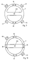
- FIG. 1 a a diagrammatic top view of a first embodiment of a regulating member according to the invention.
- FIG. 1 b a diagrammatic top view of a first embodiment of a regulating member according to the invention, with the balance being in the position of equilibrium defined by the magnets.
- FIG. 2 a cross-section view of the regulating member according to the first embodiment of the invention, having in this example two magnetic bearings and a magnetic screen.
- FIG. 3 a top view of an embodiment of a regulating member according to the invention, having fixed magnets and mobile magnets each constituted of two bipolar magnets joined side-by-side in opposition.
- FIG. 4 a top view of an embodiment of a regulating member according to the invention, having fixed magnets each constituted of two bipolar magnets joined side-by-side in opposition, and mobile magnets constituted each of a single bipolar magnet.
- FIG. 5 a top view of an embodiment of a regulating member according to the invention, having additional magnets to increase locally the stability of the point of equilibrium.
- FIG. 6 a top view of an embodiment of a regulating member according to the invention, having a right balance pivoting around a central axle.
- FIG. 7 a top view of an embodiment of a regulating member according to the invention, having a right balance pivoting around an eccentric axle.
- FIG. 8 a top view of an embodiment of a regulating member according to the invention, having four mobile magnets on the balance and four fixed magnets.
- FIG. 9 a top view of an embodiment of a regulating member according to the invention, having two mobile magnets on the balance and four fixed magnets.
- FIG. 10 a top view of an embodiment of a regulating member according to the invention, having four mobile magnets on the balance and two fixed magnets.
- FIG. 11 a top view of an embodiment of a regulating member according to the invention, having a torque element in which a mobile magnet is pushed back towards a position of equilibrium by a fixed magnet.
- FIG. 12 a top view of an embodiment of a regulating member according to the invention, having a cylinder closed at its extremities by two fixed magnets as well as a mobile magnet pushed back to an intermediary position by the two fixed magnets.
- FIG. 13 a perspective view of an embodiment of a regulating member according to the invention, wherein the mobile magnets linked to the balance and the fixed magnets are superimposed, in two parallel planes, the regulating member being in a position of equilibrium.
- FIG. 14 a perspective view of the regulating member of FIG. 13 , oscillating in an intermediary position.
- FIG. 15 a top view of an embodiment of a regulating member according to the invention, wherein the mobile magnets are directly mounted on the pallets that thus acts as balance.
- FIG. 16 a top view of an embodiment of a regulating member according to the invention, wherein the mobile magnets are directly mounted on the pallets that thus acts as balance, the fixed magnets being superimposed to the mobile magnets in a parallel plane.
- FIG. 17 a top view of an embodiment of a regulating member according to the invention, wherein the fixed magnets have a particular shape designed to guarantee a return force proportional to the angular distance, and wherein the balance has the shape of a rod.
- FIG. 18 a transversal cross section of the regulating member of FIG. 17 in the rod's plane.
- FIG. 19 a top view of another embodiment of a regulating member, wherein the return force is proportional to the angular distance.
- FIG. 20 a top view of another embodiment of a regulating member, wherein the return force is proportional to the angular distance, where this embodiment uses a magnetic ring with a magnetization that varies along the periphery.
- FIG. 21 a cross-sectional view of an embodiment of a regulating member according to the invention, having magnets of a thickness that varies radially.
- FIG. 22 a top view of an embodiment of a regulating member according to the invention, corresponding to the first embodiment but wherein a sensor and a circuit allow the amplitude of the balance's oscillations to be determined and/or controlled.
- FIG. 23 a top view of an embodiment of a regulating member according to the invention, corresponding to the first embodiment but wherein a coil generates a current whose frequency depends on the balance's oscillation frequency.
- the adjective “fixed” always refers to the movement. An element is fixed if it does not move relative to the movement, for example relative to the movement's bottom plate.
- balance designates a part oscillating under the effect of an excitation around a position of equilibrium. The more or significantly isochronous oscillations determine the running of the watch.
- the balance can be constituted by a wheel with any number of spokes, a disc, a rod, pallets, etc.
- FIG. 1 b illustrates diagrammatically a regulating member 1 having a balance 3 oscillating around an axle 300 perpendicular to the movement's bottom plate.
- the balance 3 has an annular felloe and has two radial spokes (or arms) 302 around the axle 300 .
- Screws 301 allow the balance's inertia moment to be moved easily.
- the balance constitutes an inertia mass; its mass, as well as its radius, are preferably considerable within the limits set by the will to miniaturize the movement. The considerable return force afforded by the claimed solution allows particularly considerable inertia masses to be used.
- Bi-metallic balances that deform to compensate temperature variations are also possible within the frame of the invention.
- Other means can be used to compensate the variation in intensity of the magnetic field related to the temperature.
- the balance 3 is linked with or provided with mobile permanent magnets 30 driven in rotation with the balance.
- the illustrate example has two discrete bipolar permanent magnets that are placed symmetrically relative to the axle 300 , at 180° from one another. Each magnet has a positive pole and a negative pole at equidistance to the axle 300 .
- the magnets 30 can be held mechanically or by gluing on the balance 3 .
- the magnetized parts could also be constituted by magnetized portions of the balance itself or by a magnetic path on the balance.
- the balance could thus be constituted of a magnetized ring with alternating polarities along its periphery.
- the balance could for example be magnetized in a homogenous or progressive fashion by means of a recording head, i.e. a coil generating a magnetic field of controlled intensity in a head gap.
- the regulating member further has two fixed permanent magnets 40 mounted on a bridge or on the bottom plate of the movement by any adapted means.
- the two magnets are placed in the plane of the balance 3 , symmetrically and at 180° relative to the axle 300 .
- the fixed magnets 40 could also be placed in another plane, parallel to the plane of the balance 3 .
- the magnets 40 each have a positive pole and a negative pole whose arrangement, symmetrical relative to the axle 300 , is nevertheless inverted relative to the arrangement of the poles on the mobile magnets 30 .
- the fixed magnets 40 and the mobile magnets 30 push each other back with a maximum magnetic interaction force when they are close.
- the position of equilibrium is reached by turning the balance by 90° so as to push back each mobile magnet 30 to equidistance of the two fixed magnets 40 ; the magnetic field generated by the permanent magnets 40 is minimal in this arrangement so that the force or moment necessary for leaving this position of equilibrium is also reduced.
- the magnets 30 and 40 are preferably chosen so that the magnetic repulsion force, even in the illustrated position of equilibrium, is much greater than the gravitational force exerted on the balance 3 .
- Permanent magnets made of metallic oxides, or rare earth compounds or of platinum-cobalt alloys will preferably be used to obtain considerable residual fields.
- the position of the fixed magnets, or even the position of the mobile magnets, can be adjusted in all embodiments, for example by means of screws, in order to regulate the balance's oscillation frequency.
- the balance's oscillations thus depend little on the balance's inclination.
- the revolving mass of the balance 3 (including the screws 301 ) and of the mobile magnets 30 is further preferably spread as regularly as possible around the axle 300 , so as to improve the balance's equilibrating.
- additional mechanical stops can be provided on the balance 3 and/or on a bridge in order to limit the amplitude of the balance's possible rotations and thus prevent the balance from switching from one position of equilibrium to another following a shock for example. Similar stopper elements can also be used with the other embodiments discussed further below. Additional stops can for example include elastic means to dampen the shocks at the end of travel.
- the balance 3 is made to oscillate around the position of equilibrium of FIG. 1 b by means of a driving element constituted in this example by an escapement 2 , here a conventional Swiss pallets escapement 20 .
- the escapement can also be specially adapted to take into account the balance's low amplitude of oscillation.
- escapements including electric or magnetic escapements
- the pulses given to the balance 30 are preferably so by attraction or repulsion between magnetized parts on the balance and on the escapement. It is thus possible to drive without contact.
- the amplitude and frequency of the oscillations around the position of equilibrium are determined by the force and the arrangement of the magnets and by the amplitude of the torque transmitted by the driving element. It will furthermore be noted that the balance 30 oscillates without matter deformations, so that the oscillation frequency does not depend on the metallurgic characteristics or on the aging of elastic parts.
- the regulating member of FIG. 1 b is represented in partial cross-section in FIG. 2 , where the escapement 2 has been removed from the figure to improve readability.
- the balance 3 pivots around an axle 300 perpendicular to the upper bridge 41 and to the lower bridge 42 .
- the bridges 41 and 42 preferably form a magnetic screen allowing both the balance 3 to be protected from external magnetic field and the other components of the watch to be protected by the magnetic fields generated notably by the magnets 30 and 40 .
- a screen can also, in an embodiment that is not represented, be achieved through elements distinct from the bridges, for example by means of the bottom plate, the dial, the case or dedicated elements.
- a screen an all sides can also be adopted.
- the cinematic chain between the regulating member and the hands has at least one element of synthetic material, for example a belt driven by a pulley.
- the axle 300 of the balance 2 is held in the bridges 41 , 42 by means of two bearings 410 and 420 , for example conventional shockproof bearings, Incabloc bearings or, in the preferred embodiment that is illustrated, magnetic bearings.
- the upper extremity 3001 and lower extremity 3002 of the axle 300 are magnetized or provided with magnets.
- the bearings 410 resp. 420 each have a lodging 4100 resp. 4200 whose depth and diameter are slightly greater than the corresponding dimensions of the axle 300 .
- the sides of the lodgings are magnetized with a polarization identical to that of the corresponding extremities of the axle 300 , so as to push this axle back so that it is thus held in levitation between the bearings 410 and 420 .
- the axle 300 can thus pivot without friction. This arrangement further allows the wear of the bearings 410 , 420 and of the axle 300 to be avoided.
- the balance 3 of the invention can thus oscillate without any contact with other elements, being returned to its position of equilibrium by means of the magnets 30 , 40 held by the magnetic bearings 410 , 420 and/or driven by a magnetic escapement. It is thus possible to reduce friction and wear caused by the balance's movements. These different measures can however be used independently from one another.
- FIG. 1 b illustrates a variant embodiment of regulating member similar to the embodiment of FIG. 1 b , but wherein the design of the escapement allows oscillations of the balance of greater amplitude, for example oscillations of 180° maximum, or even more by modifying the arrangement of the magnets.
- the escapement is preferably a Swiss pallets escapement that allows the balance to oscillate considerably without generating excessive oscillations of the pallets.
- the balance 3 is further provided with screws allowing possible unbalances or other sources of running perturbations.
- FIG. 3 illustrates in a simplified manner a second embodiment of regulating member according to the invention (without the escapement 2 ), wherein the fixed permanent magnets 40 and the mobile permanent magnets 30 are each constituted by two magnets joined side-by-side in opposition.
- the resulting magnetized part thus comprises two extremities provided with identical polarities.
- the two mobile magnets 30 on the balance 3 are however constituted each of a bipolar magnet, the whole having a horizontal symmetrical axis.
- FIG. 5 illustrates in a simplified manner a fourth embodiment of the invention, corresponding to FIG. 1 but wherein additional fixed permanent magnets 47 are placed opposite mobile magnets 30 at the position of equilibrium.
- the additional fixed magnets 47 and the mobile magnets 30 attract mutually at the position of equilibrium.
- the position of equilibrium is thus determined both by the repulsion of the magnets 30 and 40 and by the attraction of the magnets 30 and 47 ; the contribution of the repulsion forces is however dominant so as to limit the stability of the point of equilibrium and to allow the system to oscillate even with a low driving energy.
- the magnetic field generated by the additional fixed magnets 47 is thus preferably greatly less than the magnetic field of the magnets 40 .
- Additional magnets 47 with inverted poles, so as to reduce the stability of the point of equilibrium, can also be conceived within the frame of the invention.
- Additional magnets can also be provided at the end of travel, either on a bridge or on the balance, so as to attract or repulse the balance in this position and to reduce the variation of amplitude of the oscillations caused by perturbations.
- FIG. 6 illustrates in a simplified manner a variant embodiment of a regulating member according to the invention, having a right balance (needle-shaped) 3 pivoting around a central axle 300 .
- the two extremities of the balance 3 are provided with magnets 30 pushed back towards the position of equilibrium by the fixed magnets 40 mounted on a bridge that is not represented.
- the inertia mass of the balance 3 in this embodiment is greatly reduced, this arrangement makes it possible to reduce the space requirements of the regulating member.
- FIG. 7 illustrates a top view of an embodiment of a regulating member according to the invention, having a right balance 3 similar to that of FIG. 6 but pivoting around an eccentric axle 300 . Only the extremity of the balance 3 furthest from the axle 300 is provided in this embodiment with a magnet pushed back towards the illustrated position of equilibrium by means of two magnets 40 .
- the escapement could be obtained by extending the balance 3 with a part in the shape of pallets directly actuated by the pallets wheel.
- FIG. 8 illustrates a top view of a sixth embodiment of a regulating member according to the invention.
- the regulating member is similar to that of FIGS. 1 and 2 , but has four mobile magnets 30 distributed at 90° to one another on a bridge that is not represented. This arrangement allows notably the distance between the fixed magnets and the mobile magnets to be reduced whilst multiplying the number of magnets, so that the resulting magnetic interaction force, and thus the return torque, are increased.
- Arrangements having more than four mobile magnets and/or more than four fixed magnets can also be conceived. Furthermore, as mentioned, it is also possible to use magnetized parts with a plurality of zones of alternating magnetic polarities.
- a magnetic field alternated all-or-nothing or according to a sinusoidal function for example, can for example be written by a magnetic head on the periphery of the balance and/or on a fixed element connected to the movement.
- FIG. 9 illustrates a top view of an embodiment of a regulating member wherein the number of mobile magnets 30 on the balance is less than the number of fixed magnets 40 .
- Each mobile magnet is thus subjected to the action of a pair of fixed magnets; each fixed magnet acts on only one mobile magnet. Arrangements having two fixed magnets and a single mobile magnet can also be conceived.
- FIG. 10 illustrates a top view of an embodiment of a regulating member wherein the number of mobile magnets 30 on the balance is greater than the number of fixed magnets 40 .
- Each mobile magnet is thus subjected to the action of a single fixed magnet; each fixed magnet however acts on two mobile magnets.
- the amplitude of oscillations of the balance of FIG. 9 is very limited, less than 90°. It is thus possible to make it oscillate it very fast and to achieve a very fine resolution for measuring time.
- very fast oscillations of small amplitude have the disadvantage of amplifying the influence of perturbations caused at each cycle by friction with the pallets and the balance. According to the desired resolution and the quality in which the escapement is made, it can thus be desirable to increase the amplitude of the oscillations beyond 180° rather than seeking to reduce it.
- arrangements having two mobile magnets and a single fixed magnet are also possible, or even a single fixed magnet and a single mobile magnet that allow oscillations of nearly 360° to be achieved.
- the rotating inertia mass by linking the balance 3 with another oscillating mass through a cinematic chain, for example a gearing on the balance's axle, or through a belt.
- the balance's oscillations are thus transmitted to an additional oscillating mass.
- Gear ratios between the balance 3 and the additional oscillating mass further make it possible to achieve a different amplitude of oscillation on these two components. It is for example conceivable to have the balance 3 oscillate by 180° and to connect it cinematically through a gear of ratio 8 to another rotating mass that completes oscillations of 8 ⁇ 180°, i.e. four turns, at each cycle.
- FIG. 11 illustrates an embodiment of the invention wherein the balance is constituted by a mobile magnet 30 whose trajectory is constrained by a guide 43 , for example a slide-way, a slide or a rail, in this example an o-ring slide-way.
- the arrangement of the poles of the fixed magnet 40 is opposed to the arrangement of the poles of the mobile magnet 30 , so that the position of equilibrium is reached when the mobile magnet is diametrically opposite the fixed magnet.
- This arrangement makes it possible to use a single mobile magnet and a single fixed magnet.
- Different, not annular, shapes of slide-ways, rails or slides 43 can also be conceived; furthermore, the fixed magnet 40 could be outside the slide.
- the balance 30 is driven through the pallets 20 actuated by an escapement wheel that is not represented and that is articulated around the axle 300 .
- the pallets 20 extend the balance's arm outside the slide 43 .
- a magnetic escapement can also be used in the frame of the invention.
- FIG. 12 illustrates an embodiment of the invention wherein the balance 3 is constituted by or has a magnet 3 moving linearly in a cylinder, a slide-way or along a rail 43 whose two extremities are closed by fixed magnets 40 .
- the polarities of the magnets 30 and 40 are placed in such a manner that the magnetic interaction force tends to push back the mobile magnet 30 in levitation half-way between the two fixed magnets 40 , as illustrated in FIG. 12 .
- the balance 3 can be made to oscillate by means of an element external to the rail 43 and following the movements of the balance 2 through a mechanical or magnetic connection.
- FIGS. 11 and 12 The balance's movement in FIGS. 11 and 12 is constrained by the guides 43 , which causes an energy loss and a loss of accuracy in the case of deformation or dilatation of the guiding surfaces.
- Balances oscillating in a plane along two or even degrees of freedom can also be conceived in the frame of the invention.
- a plurality of fixed permanent magnets must in this case be provided for pushing back the balance towards a point of equilibrium around which a driving element makes it oscillate.
- the small thickness available in a wristwatch and the difficulties of making the escapement make such solutions more difficult to apply.
- FIGS. 13 and 14 illustrate an embodiment of the regulating member having a mobile magnet 30 constituted by a disc mounted at the center of the balance 3 .
- the disk 30 has sectors, in the illustrated embodiment two sectors, provided with alternating magnetic polarities.
- the fixed magnet 50 is mounted above the mobile magnet 30 , in a parallel plane, and also constituted by a disc provided with sectors of alternating polarities.
- the balance is positioned so that the sectors of opposite polarity of the two magnets 30 and 40 are exactly superimposed.
- the balance is brought in this position essentially by attracting opposite poles of the two magnets and, in a lesser measure, by repulsion of the identical poles.
- the balance oscillates around this stable position of equilibrium when a perturbation is transmitted to it for example by the escapement, not represented in the figure.
- FIGS. 13 and 14 It is also possible to modify the arrangement of the FIGS. 13 and 14 for example by using magnets 30 and 40 provided with more than two sectors of alternating polarities, or by using several fixed magnets in a first plane and several mobile magnets in a parallel plane.
- the mobile magnets can for example also be placed at the balance's periphery and the mobile magnets above these positions. It is also possible to use a different number of fixed magnets and mobile magnets; for example, it would also be possible within the frame of the invention to mount the mobile magnet 30 between a fixed magnet on an upper plane, as illustrated in the figures, and an additional fixed magnet, not represented, in a lower parallel plane.
- FIG. 15 illustrates a top view of an embodiment of a regulating member wherein the mobile magnets 30 are directly mounted on the pallets 20 .
- Fixed magnets 40 tend to push back and make oscillate these mobile magnets around a position of equilibrium.
- the pallets 20 themselves thus act as balance.
- This embodiment although conceivable, has however the disadvantage of being more shock sensitive, the pallets' inertia being generally insufficient for guaranteeing an isochronous oscillation. Pallets with strong inertia would be conceivable but would require considerable excitation energy to make them oscillate.
- FIG. 16 combines the characteristics of the solutions illustrated in FIGS. 13 and 15 , i.e. pallets 20 acting themselves as balance and fixed and permanent magnets constituted by superimposed discs provided with sectors of alternating polarities.
- this ratio guarantees a stable isochronous oscillation only when the oscillations satisfy very particular conditions (for example when their amplitude is low).
- FIG. 17 illustrates an embodiment of a regulating member wherein the ratio between the distance of the balance (i.e. its angular distance relative to the resting position 9 and the returning force or torque obeys a different ratio.
- the volume of the fixed magnets 40 increases when, within the oscillation range p, one moves away from the resting position by an angular distance d, so as to increase the return force at a distance from this position.
- the mobile magnets 30 on the balance 3 are on the other hand of constant size along the trajectory of the oscillations. Mechanical or magnetic stops, not represented, can be provided to force the balance to remain within the oscillation range p even in the case of shocks for example.
- the escapement tends to make the balance turn anticlockwise, a rotation that is countered by the magnets' repulsion.
- the surface of the fixed magnets 40 in a plane parallel to the plane of the oscillations of the balance 3 increases inside the oscillation field p with the cube of the angular distance d, or possibly according to d 4 .
- the fixed magnets 40 thus have the shape of sectioned moons.
- FIG. 19 Another possible arrangement is illustrated on FIG. 19 , wherein the balance oscillates around the axle 300 on each side of the resting position.
- the mobile magnets 30 of FIG. 17 move along a circular trajectory in a plane parallel to the plane of the fixed magnets 40 . It is however also possible, in order to increase the magnetic interaction, to have the mobile magnets turn between two parallel planes each provided with one or several fixed magnets 40 . Conversely, it is also possible to provide a balance 3 composed of several superimposed pates, turning on a same axle and all provided with mobile magnets 30 ; the different mobile plates are then separated by one or several bridges bearing the fixed magnets. Other types of stacking of any number of planes of mobile magnets and of planes of fixed magnets can be conceived.
- FIG. 20 illustrates an embodiment of the invention wherein the balance 3 is provided with three spokes 302 , of which at least one is magnetized with opposed poles at each radial extremity.
- the fixed magnets 40 which are constituted by a magnetic ring 40 with a polarization in one direction inside and in the opposite direction outside.
- the density of the magnetic field generated by the fixed magnet varies along the balance's periphery so as to preferably ensure a return force that varies linearly with the balance's angular position.
- the balance could also be provided with a magnetic peripheral ring or of discrete magnets on the periphery, with a magnetization that varies along the periphery.
- the progressive magnetization of the fixed magnet can for example be obtained by magnetizing it by means of a recording head, as previously mentioned.
- the magnetic material is saturated, it may be necessary to limit the balance's oscillations in the portion that guarantees the desired ratio between the balance's angular position and the return force.
- magnetizing the entire balance it would be conceivable to magnetize only a magnetic path fastened onto the latter, in parallel or perpendicularly to the plane of the balance.
- An additional fixed permanent magnet 47 is place opposite the mobile magnet 30 at the maximum repulsion position, in order to prevent the balance from reaching and then overshooting this position.
- This magnet 47 thus acts as magnetic stop to move the balance away from a non-desirable position of equilibrium, without having the disadvantages of mechanical stops causing shocks likely to disturb the isochronous running of the balance.
- the permanent magnets are constituted by a continuous ring. It is however also possible to use a discontinuous ring, for example provided with one or several head gaps or having discrete magnets.
- the volume of the fixed (and/or mobile) magnets thus varies in a continuous manner along the balance's circular trajectory, so as to control the ration between the return force and the balance's angular position.
- FIG. 21 illustrates an embodiment of the invention wherein the thickness of the mobile magnets 30 increases radially whilst the thickness of the fixed magnets 40 diminishes by moving away from the rotation axle 300 .
- An inverted arrangement, providing a gap between the fixed and mobile magnets, can also be adopted.
- the radial thickness variation can also be combined with a variation along the periphery of the regulating member.
- the radial and/or circumferential variation in the thickness of the magnets 30 , 40 can also be used with the embodiments of FIGS. 13 and 14 having superimposed magnets.
- FIG. 33 illustrates an embodiment of the regulating member illustrated in FIGS. 1 to 2 , and furthermore has a plurality of electrodes 44 whose electric property varies according to the electric field to which they are subjected.
- the electrodes 44 thus allow the turning magnetic field generated by the oscillations of the mobile magnets 30 to be detected or even measured.
- the electrodes 44 can for example be constituted by magnetoresistive electrodes or by Hall sensors. They can be connected to one another and to an integrated circuit 46 through conducting paths 440 according to different topologies.
- the circuit 440 allows the amplitude of the oscillations of the balance 430 and/or the oscillation frequency to be determined.
- the circuit 46 can be powered by an independent energy source, for example a battery, or by a coil generating an alternating current under the action of the balance's displacements, as illustrated in connection with FIG. 18 mentioned further above. An electronic correction of the running of a mechanical watch can thus be achieved.
- an independent energy source for example a battery
- a coil generating an alternating current under the action of the balance's displacements as illustrated in connection with FIG. 18 mentioned further above.
- Measuring the frequency and/or amplitude of the oscillations of the balance 30 allows for example possible irregularities in the running frequency to be detected.
- This information can be used to correct the watch's running, for example by exerting a correction torque on the balance 30 by means of electro-magnets, not represented, or by other electro-mechanical means, so as to correct the amplitude and frequency of the oscillations.
- This information can also be used for displaying an end-of-travel signal, so as to signal to the user that the watch's running is becoming inaccurate.
- FIG. 23 illustrates an embodiment of the regulating member wherein a coil 45 opposite each mobile magnet 30 generates a current proportional to the magnetic field generated when this magnet moves close to the coil.
- a coil 45 opposite each mobile magnet 30 generates a current proportional to the magnetic field generated when this magnet moves close to the coil.
- the illustrated coils generate an approximately sinusoidal current whose frequency corresponds to the balance's oscillation frequency. This frequency can be measured by a circuit 45 , for example by comparing it to a reference frequency supplied by a quartz, in order for example to inform the user in case of irregular frequency and/or to correct this frequency, for example by injecting a compensation current into the coil 45 .
- the circuit 46 can include a rectifier and thus be powered itself by the current generated by the coil 45 .
- the current generated by the coil can also be used to power a circuit supplying any type of function one wishes to give a mechanical watch without battery.
- the described regulating member can be used in a movement for autonomous wristwatch or in an auxiliary module, for example a chronograph module, designed to be superimposed to a basis module.
- the different regulating members described all have at least one mobile permanent magnet and at least one fixed permanent magnet. Constructions without fixed permanent magnet or without mobile permanent magnet can however be conceived in the frame of the invention.
- the inventive regulating member is preferably mounted in a mechanical movement, preferably without a battery, and in a watch-case that shows at least part of the balance, which allows the user to check its displacements at any time.
Landscapes
- Physics & Mathematics (AREA)
- General Physics & Mathematics (AREA)
- Electromagnetism (AREA)
- Engineering & Computer Science (AREA)
- Power Engineering (AREA)
- Magnetic Bearings And Hydrostatic Bearings (AREA)
- Vibration Prevention Devices (AREA)
- Electric Clocks (AREA)
- Reciprocating, Oscillating Or Vibrating Motors (AREA)
- Apparatuses For Generation Of Mechanical Vibrations (AREA)
- Electromechanical Clocks (AREA)
- Switches With Compound Operations (AREA)
- Permanent Magnet Type Synchronous Machine (AREA)
- Micromachines (AREA)
- Magnetically Actuated Valves (AREA)
Applications Claiming Priority (3)
| Application Number | Priority Date | Filing Date | Title |
|---|---|---|---|
| CH17682004 | 2004-10-26 | ||
| CH2004CH-01768 | 2004-10-26 | ||
| PCT/EP2005/055582 WO2006045824A2 (fr) | 2004-10-26 | 2005-10-26 | Organe reglant pour montre bracelet, et mouvement mecanique comportant un tel organe reglant |
Related Parent Applications (1)
| Application Number | Title | Priority Date | Filing Date |
|---|---|---|---|
| PCT/EP2005/055582 Continuation WO2006045824A2 (fr) | 2004-10-26 | 2005-10-26 | Organe reglant pour montre bracelet, et mouvement mecanique comportant un tel organe reglant |
Publications (2)
| Publication Number | Publication Date |
|---|---|
| US20070201317A1 US20070201317A1 (en) | 2007-08-30 |
| US7396154B2 true US7396154B2 (en) | 2008-07-08 |
Family
ID=34974327
Family Applications (1)
| Application Number | Title | Priority Date | Filing Date |
|---|---|---|---|
| US11/789,817 Active US7396154B2 (en) | 2004-10-26 | 2007-04-26 | Regulating element for wristwatch and mechanical movement comprising one such regulating element |
Country Status (10)
| Country | Link |
|---|---|
| US (1) | US7396154B2 (de) |
| EP (2) | EP1805565B1 (de) |
| JP (1) | JP4607966B2 (de) |
| KR (1) | KR100918186B1 (de) |
| CN (1) | CN101091141B (de) |
| AT (2) | ATE481662T1 (de) |
| DE (1) | DE602005023633D1 (de) |
| HK (1) | HK1113830A1 (de) |
| RU (1) | RU2356079C2 (de) |
| WO (1) | WO2006045824A2 (de) |
Cited By (8)
| Publication number | Priority date | Publication date | Assignee | Title |
|---|---|---|---|---|
| US20080279052A1 (en) * | 2005-04-06 | 2008-11-13 | Rolex S.A. | Watch Escapement |
| US20100128573A1 (en) * | 2006-07-11 | 2010-05-27 | Bernardus Johannes Meijer | Clockwork |
| US20120269043A1 (en) * | 2009-11-02 | 2012-10-25 | Lvmh Swiss Manufactures Sa | Regulating member for a wristwatch, and timepiece comprising such a regulating member |
| US9459590B1 (en) | 2013-04-22 | 2016-10-04 | Donald J. Lecher | Methods and devices using a series of sequential timekeeping periods |
| US9612577B2 (en) | 2013-04-22 | 2017-04-04 | Donald J. Lecher | Device displaying a series of sequential timekeeping periods |
| US20170211953A1 (en) * | 2016-01-27 | 2017-07-27 | Samsung Display Co., Ltd. | Display apparatus having indicator needle |
| US10386791B2 (en) * | 2016-12-23 | 2019-08-20 | The Swatch Group Research And Development Ltd | Timepiece assembly comprising a mechanical oscillator associated with a regulating device |
| US11599065B2 (en) * | 2018-06-19 | 2023-03-07 | The Swatch Group Research And Development Ltd | Timepiece comprising a mechanical movement wherein the working is regulated by an electromechanical device |
Families Citing this family (50)
| Publication number | Priority date | Publication date | Assignee | Title |
|---|---|---|---|---|
| CH697273B1 (fr) * | 2006-07-26 | 2008-07-31 | Detra Sa | Dispositif d'échappement électromécanique et pièce d'horlogerie munie d'un tel dispositif |
| DE602007011393D1 (de) * | 2007-03-21 | 2011-02-03 | Richemont Int Sa | Unruh für Uhrwerk |
| TWI362574B (en) * | 2008-09-25 | 2012-04-21 | Pegatron Corp | Multifunction time display |
| EP2287683B1 (de) * | 2009-08-17 | 2012-10-31 | The Swatch Group Research and Development Ltd. | Magnetic protection for hairspring in a timepiece |
| CH702188B1 (fr) | 2009-11-02 | 2017-12-29 | Lvmh Swiss Mft Sa | Organe réglant pour montre bracelet, et pièce d'horlogerie comportant un tel organe réglant. |
| CH702156B1 (fr) * | 2009-11-13 | 2017-08-31 | Nivarox Far Sa | Résonateur balancier-spiral pour une pièce d'horlogerie. |
| EP2336832B1 (de) * | 2009-12-21 | 2020-12-02 | Rolex Sa | Schweizer Ankerhemmung |
| EP2450758B1 (de) | 2010-11-09 | 2017-01-04 | Montres Breguet SA | Magnetischer Drehzapfen und elektrostatischer Dhrerzapfen |
| CH704685B1 (fr) * | 2011-03-23 | 2015-12-15 | Lvmh Swiss Mft Sa | Organe réglant magnétique pour montre mécanique. |
| EP2551732B1 (de) * | 2011-07-29 | 2020-05-06 | Rolex S.A. | Unruh mit optimierter Drehbewegung |
| EP2565727A1 (de) * | 2011-09-05 | 2013-03-06 | Nivarox-FAR S.A. | Verfahren zum Zusammenbau einer Uhrteilgruppe von Unruh - Spiralfeder und Einstellung in der Schwingungsfrequenz |
| JP5882089B2 (ja) * | 2012-03-08 | 2016-03-09 | セイコーインスツル株式会社 | 温度補償型てんぷ、時計用ムーブメント及び時計 |
| JP5840043B2 (ja) * | 2012-03-22 | 2016-01-06 | セイコーインスツル株式会社 | てんぷ、時計用ムーブメント、および時計 |
| JP5918438B2 (ja) * | 2012-03-29 | 2016-05-18 | ニヴァロックス−ファー ソシエテ アノニム | 可動フレームを備えた可撓性エスケープ機構 |
| EP2706416B1 (de) * | 2012-09-07 | 2015-11-18 | The Swatch Group Research and Development Ltd | Flexibler Anker mit konstanter Kraft |
| RU2526561C1 (ru) * | 2012-12-21 | 2014-08-27 | Общество с ограниченной ответственностью "Часовой завод "НИКА" | Наручные таинственные часы |
| EP2762985B1 (de) * | 2013-02-04 | 2018-04-04 | Montres Breguet SA | Magnetische oder elektrostatische Drehung eines drehbaren Bauteils einer Uhr |
| CN104007650B (zh) * | 2013-02-25 | 2017-09-05 | 精工电子有限公司 | 温度补偿型摆轮及其制造方法、钟表用机芯、机械式钟表 |
| JP6025202B2 (ja) * | 2013-02-25 | 2016-11-16 | セイコーインスツル株式会社 | 温度補償型てんぷ、時計用ムーブメント、及び機械式時計 |
| JP6025203B2 (ja) * | 2013-02-25 | 2016-11-16 | セイコーインスツル株式会社 | 温度補償型てんぷ、時計用ムーブメント、機械式時計、及び温度補償型てんぷの製造方法 |
| CH707990B1 (fr) * | 2013-04-24 | 2017-11-15 | Lvmh Swiss Mft Sa | Mouvement de montre mécanique comportant un tourbillon et un organe réglant magnétique. |
| US9746829B2 (en) * | 2013-12-23 | 2017-08-29 | Nivarox-Far S.A. | Contactless cylinder escapement mechanism for timepieces |
| RU2629168C1 (ru) * | 2013-12-23 | 2017-08-24 | Эта Са Мануфактюр Орложэр Сюис | Механизм синхронизации часов |
| EP2998801A1 (de) * | 2014-09-19 | 2016-03-23 | The Swatch Group Research and Development Ltd. | Magnetische Ankerhemmung, und Gangeinstellvorrichtung eines Uhrwerks |
| EP2908188B1 (de) * | 2014-02-17 | 2018-06-27 | The Swatch Group Research and Development Ltd. | Regulierung eines resonators einer uhr durch einwirkung auf die steifheit eines elastischen rückstellmittels |
| EP3001259A1 (de) * | 2014-09-26 | 2016-03-30 | ETA SA Manufacture Horlogère Suisse | Einstellvorrichtung des Gangs eines mechanischen Uhrwerks |
| EP2998799A1 (de) | 2014-09-18 | 2016-03-23 | Montres Breguet SA | Kontaktlose Rastung |
| CN105738034B (zh) * | 2014-12-12 | 2018-05-22 | 天津海鸥表业集团有限公司 | 激光校正摆轮重心偏移的平衡测量方法及测量切削装置 |
| EP3035131A1 (de) | 2014-12-18 | 2016-06-22 | Jeanneret, Marc Andre | Oszillator für Uhrwerk |
| EP3128379B1 (de) * | 2015-08-04 | 2019-10-02 | The Swatch Group Research and Development Ltd. | Hemmung mit hemmungsrad mit feldrampen und vorrichtung zur rücklaufsicherung |
| EP3130966B1 (de) | 2015-08-11 | 2018-08-01 | ETA SA Manufacture Horlogère Suisse | Mechanisches uhrwerk, das mit einem bewegungsrückkopplungssysteme ausgestattet ist |
| WO2017033688A1 (ja) * | 2015-08-25 | 2017-03-02 | シチズン時計株式会社 | 時計の脱進機 |
| EP3182224B1 (de) * | 2015-12-18 | 2019-05-22 | Montres Breguet S.A. | Sicherheitsregulator für uhrhemmung |
| EP3185083B1 (de) | 2015-12-23 | 2018-11-14 | Montres Breguet S.A. | Mechanischer uhrmechanismus mit einer ankerhemmung |
| JP6653181B2 (ja) * | 2016-01-21 | 2020-02-26 | セイコーインスツル株式会社 | トゥールビヨン、ムーブメント及び時計 |
| CN106707718B (zh) * | 2017-03-01 | 2019-01-29 | 谭泽华 | 钟表分轴冲击擒纵器 |
| EP3489763B1 (de) * | 2017-11-22 | 2021-06-16 | Nivarox-FAR S.A. | Anker für die bewegungshemmung eines uhrwerks |
| CN108561530B (zh) * | 2017-12-04 | 2020-12-29 | 安徽未来机电科技有限公司 | 一种减速器用的摆轮组件 |
| JP7060988B2 (ja) * | 2018-03-16 | 2022-04-27 | セイコーインスツル株式会社 | 温度補償型てんぷ、ムーブメント及び時計 |
| EP3579058B1 (de) * | 2018-06-07 | 2021-09-15 | Montres Breguet S.A. | Uhr, die ein tourbillon umfasst |
| CN108953896B (zh) * | 2018-08-06 | 2020-10-09 | 广州市纳祺科技有限公司 | 一种自动微转动全方位无死角监控支架 |
| EP3620867B1 (de) * | 2018-09-04 | 2022-01-05 | The Swatch Group Research and Development Ltd | Uhr, die einen mechanischen oszillator umfasst, dessen durchschnittliche frequenz mit der eines elektronischen referenzoszillators synchronisiert ist |
| EP3627242B1 (de) | 2018-09-19 | 2021-07-21 | The Swatch Group Research and Development Ltd | Optimierter magnetomechanischer uhrhemmungsmechanismus |
| EP3650954A1 (de) * | 2018-11-09 | 2020-05-13 | Montres Breguet S.A. | Regulierorgan für armbanduhr |
| KR102066047B1 (ko) * | 2018-12-13 | 2020-01-14 | 오성근 | 시간 조절이 가능한 기계식 타이머 |
| EP3719588B1 (de) * | 2019-04-03 | 2021-11-03 | The Swatch Group Research and Development Ltd | Automatisch regulierbarer oszillator einer uhr |
| EP3767397B1 (de) * | 2019-07-19 | 2022-04-20 | The Swatch Group Research and Development Ltd | Uhrwerk mit einem drehelement, das eine magnetisierte struktur mit periodischer konfigurierung besitzt |
| IT202000013213A1 (it) * | 2020-06-04 | 2021-12-04 | Antonio Corazza | Dispositivo dotato di strutture mobili, tali per effetto dell'interagire tra i magneti integrati nelle strutture medesime |
| US11703807B2 (en) * | 2020-08-18 | 2023-07-18 | Kevin Farrelly Nolan | Magnetically coupled dead beat escapement breakaway mechanism |
| EP4202564A1 (de) * | 2021-12-22 | 2023-06-28 | The Swatch Group Research and Development Ltd | Mechanisches uhrwerk mit einer magnetisch schwenkbaren unruh |
Citations (15)
| Publication number | Priority date | Publication date | Assignee | Title |
|---|---|---|---|---|
| US3161012A (en) | 1962-08-22 | 1964-12-15 | Ebauches Sa | Driving balance-wheel for an electrical timepiece |
| US3524118A (en) * | 1967-09-21 | 1970-08-11 | Reich Robert W | Electronic oscillating motor timepiece drive |
| US3626691A (en) * | 1968-09-06 | 1971-12-14 | Far Fab Assortiments Reunies | Watch balance |
| US3665699A (en) | 1970-04-16 | 1972-05-30 | Centre Electron Horloger | Device for locking an electro-dynamically maintained balance/balance-spring |
| US3670492A (en) * | 1969-05-28 | 1972-06-20 | Citizen Watch Co Ltd | Balance wheel assembly |
| US3714773A (en) | 1971-11-01 | 1973-02-06 | Timex Corp | Amplitude control means for balance wheel oscillator |
| US3813372A (en) * | 1970-07-27 | 1974-05-28 | Mitsubishi Rayon Co | Method of manufacturing acrylonitrile polymers having an excellent whiteness |
| US3851461A (en) | 1971-02-10 | 1974-12-03 | Timex Corp | Balance wheel |
| US3921386A (en) | 1973-02-24 | 1975-11-25 | Itt | Circuit for synchronizing watches driven by a coil-magnet system |
| DE2424212A1 (de) | 1974-05-17 | 1975-11-27 | Mauthe Gmbh Friedr | Oszillator als gangordner fuer uhren |
| US3937001A (en) | 1972-11-21 | 1976-02-10 | Berney Jean Claude | Watch movement driven by a spring and regulated by an electronic circuit |
| GB1444627A (en) | 1972-08-04 | 1976-08-04 | Itt | Method of synchronizing mechanical vibrators for use in timepieces |
| US4266291A (en) | 1977-12-27 | 1981-05-05 | Iida Sankyo Co., Ltd. | Electromagnetic swing device |
| US20030137901A1 (en) | 2000-12-20 | 2003-07-24 | Takeshi Tokoro | Mechanical timepiece with posture detector and the posture detector |
| EP1521142A1 (de) | 2003-10-01 | 2005-04-06 | Asulab S.A. | Uhr mit einem mechanischen Uhrwerk, das mit einem elektronischen Regulator gekoppelt ist |
Family Cites Families (2)
| Publication number | Priority date | Publication date | Assignee | Title |
|---|---|---|---|---|
| CH613594B (fr) * | 1971-05-04 | Ebauches Sa | Procede de synchronisation a une frequence moyenne f des oscillations d'un resonateur mecanique d'instrument de mesure du temps et dispositif pour la mise en oeuvre de ce procede. | |
| JP4003382B2 (ja) * | 2000-07-14 | 2007-11-07 | セイコーエプソン株式会社 | 発電機および電子制御式機械時計 |
-
2005
- 2005-10-26 AT AT05801381T patent/ATE481662T1/de not_active IP Right Cessation
- 2005-10-26 KR KR1020077011896A patent/KR100918186B1/ko not_active IP Right Cessation
- 2005-10-26 RU RU2007119565/28A patent/RU2356079C2/ru not_active IP Right Cessation
- 2005-10-26 JP JP2007538419A patent/JP4607966B2/ja not_active Expired - Fee Related
- 2005-10-26 CN CN2005800449626A patent/CN101091141B/zh not_active Expired - Fee Related
- 2005-10-26 WO PCT/EP2005/055582 patent/WO2006045824A2/fr active Application Filing
- 2005-10-26 EP EP05801381A patent/EP1805565B1/de active Active
- 2005-10-26 AT AT10176455T patent/ATE557328T1/de active
- 2005-10-26 EP EP10176455A patent/EP2282240B1/de active Active
- 2005-10-26 DE DE602005023633T patent/DE602005023633D1/de active Active
-
2007
- 2007-04-26 US US11/789,817 patent/US7396154B2/en active Active
-
2008
- 2008-04-09 HK HK08103991.5A patent/HK1113830A1/xx not_active IP Right Cessation
Patent Citations (15)
| Publication number | Priority date | Publication date | Assignee | Title |
|---|---|---|---|---|
| US3161012A (en) | 1962-08-22 | 1964-12-15 | Ebauches Sa | Driving balance-wheel for an electrical timepiece |
| US3524118A (en) * | 1967-09-21 | 1970-08-11 | Reich Robert W | Electronic oscillating motor timepiece drive |
| US3626691A (en) * | 1968-09-06 | 1971-12-14 | Far Fab Assortiments Reunies | Watch balance |
| US3670492A (en) * | 1969-05-28 | 1972-06-20 | Citizen Watch Co Ltd | Balance wheel assembly |
| US3665699A (en) | 1970-04-16 | 1972-05-30 | Centre Electron Horloger | Device for locking an electro-dynamically maintained balance/balance-spring |
| US3813372A (en) * | 1970-07-27 | 1974-05-28 | Mitsubishi Rayon Co | Method of manufacturing acrylonitrile polymers having an excellent whiteness |
| US3851461A (en) | 1971-02-10 | 1974-12-03 | Timex Corp | Balance wheel |
| US3714773A (en) | 1971-11-01 | 1973-02-06 | Timex Corp | Amplitude control means for balance wheel oscillator |
| GB1444627A (en) | 1972-08-04 | 1976-08-04 | Itt | Method of synchronizing mechanical vibrators for use in timepieces |
| US3937001A (en) | 1972-11-21 | 1976-02-10 | Berney Jean Claude | Watch movement driven by a spring and regulated by an electronic circuit |
| US3921386A (en) | 1973-02-24 | 1975-11-25 | Itt | Circuit for synchronizing watches driven by a coil-magnet system |
| DE2424212A1 (de) | 1974-05-17 | 1975-11-27 | Mauthe Gmbh Friedr | Oszillator als gangordner fuer uhren |
| US4266291A (en) | 1977-12-27 | 1981-05-05 | Iida Sankyo Co., Ltd. | Electromagnetic swing device |
| US20030137901A1 (en) | 2000-12-20 | 2003-07-24 | Takeshi Tokoro | Mechanical timepiece with posture detector and the posture detector |
| EP1521142A1 (de) | 2003-10-01 | 2005-04-06 | Asulab S.A. | Uhr mit einem mechanischen Uhrwerk, das mit einem elektronischen Regulator gekoppelt ist |
Non-Patent Citations (1)
| Title |
|---|
| International Search Report Dated Jun. 29, 2006. |
Cited By (13)
| Publication number | Priority date | Publication date | Assignee | Title |
|---|---|---|---|---|
| US20080279052A1 (en) * | 2005-04-06 | 2008-11-13 | Rolex S.A. | Watch Escapement |
| US7686503B2 (en) * | 2005-04-06 | 2010-03-30 | Rolex S.A. | Watch escapement |
| US20100128573A1 (en) * | 2006-07-11 | 2010-05-27 | Bernardus Johannes Meijer | Clockwork |
| US20120269043A1 (en) * | 2009-11-02 | 2012-10-25 | Lvmh Swiss Manufactures Sa | Regulating member for a wristwatch, and timepiece comprising such a regulating member |
| US8534910B2 (en) * | 2009-11-02 | 2013-09-17 | Lvmh Swiss Manufactures Sa | Regulating member for a wristwatch, and timepiece comprising such a regulating member |
| US9612577B2 (en) | 2013-04-22 | 2017-04-04 | Donald J. Lecher | Device displaying a series of sequential timekeeping periods |
| US9459590B1 (en) | 2013-04-22 | 2016-10-04 | Donald J. Lecher | Methods and devices using a series of sequential timekeeping periods |
| US9880520B2 (en) | 2013-04-22 | 2018-01-30 | Donald J. Lecher | Hour dial displaying a series of sequential timekeeping periods |
| US10037005B2 (en) | 2013-04-22 | 2018-07-31 | Donald J. Lecher | Methods using a series of sequential timekeeping periods |
| US20170211953A1 (en) * | 2016-01-27 | 2017-07-27 | Samsung Display Co., Ltd. | Display apparatus having indicator needle |
| US10451452B2 (en) * | 2016-01-27 | 2019-10-22 | Samsung Display Co., Ltd. | Display apparatus having indicator needle |
| US10386791B2 (en) * | 2016-12-23 | 2019-08-20 | The Swatch Group Research And Development Ltd | Timepiece assembly comprising a mechanical oscillator associated with a regulating device |
| US11599065B2 (en) * | 2018-06-19 | 2023-03-07 | The Swatch Group Research And Development Ltd | Timepiece comprising a mechanical movement wherein the working is regulated by an electromechanical device |
Also Published As
| Publication number | Publication date |
|---|---|
| WO2006045824A3 (fr) | 2006-08-17 |
| US20070201317A1 (en) | 2007-08-30 |
| DE602005023633D1 (de) | 2010-10-28 |
| EP1805565B1 (de) | 2010-09-15 |
| RU2356079C2 (ru) | 2009-05-20 |
| CN101091141B (zh) | 2012-03-21 |
| HK1113830A1 (en) | 2008-10-17 |
| EP2282240A2 (de) | 2011-02-09 |
| EP2282240A3 (de) | 2011-02-23 |
| ATE481662T1 (de) | 2010-10-15 |
| WO2006045824A2 (fr) | 2006-05-04 |
| JP4607966B2 (ja) | 2011-01-05 |
| KR20070067732A (ko) | 2007-06-28 |
| KR100918186B1 (ko) | 2009-09-22 |
| JP2008518221A (ja) | 2008-05-29 |
| ATE557328T1 (de) | 2012-05-15 |
| EP1805565A2 (de) | 2007-07-11 |
| EP2282240B1 (de) | 2012-05-09 |
| RU2007119565A (ru) | 2008-12-10 |
| CN101091141A (zh) | 2007-12-19 |
Similar Documents
| Publication | Publication Date | Title |
|---|---|---|
| US7396154B2 (en) | Regulating element for wristwatch and mechanical movement comprising one such regulating element | |
| US8534910B2 (en) | Regulating member for a wristwatch, and timepiece comprising such a regulating member | |
| CN100480902C (zh) | 具有与电子调速器相联的机械机芯的时计 | |
| US8794823B2 (en) | Magnetic resonator for a mechanical timepiece | |
| CN100480901C (zh) | 具有与电子调速器相联的机械机芯的时计 | |
| US3648453A (en) | Electric timepiece | |
| JP6723256B2 (ja) | 3次元磁性共振を有する調速機を備える時間管理ムーブメント | |
| JP6853082B2 (ja) | 調速機、電子制御式機械時計、電子機器 | |
| TWI352882B (en) | Regulating organ for wristwatch and mechanical mov | |
| JP2017538124A (ja) | 時計ムーブメント用発振器 | |
| US11644797B2 (en) | Inertia mobile component for horological resonator with magnetic interaction device insensitive to the external magnetic field | |
| US3808792A (en) | Drive mechanism of an electric timepiece | |
| GB2533960A (en) | An escapement comprising a magnetically braked escape wheel and a tuned mechanical resonator for time keeping in clocks, watches, chronometers and other |
Legal Events
| Date | Code | Title | Description |
|---|---|---|---|
| AS | Assignment |
Owner name: TAG HEUER SA, SWITZERLAND Free format text: ASSIGNMENT OF ASSIGNORS INTEREST;ASSIGNOR:HOULON, THOMAS;REEL/FRAME:019286/0509 Effective date: 20061121 |
|
| FEPP | Fee payment procedure |
Free format text: PAYOR NUMBER ASSIGNED (ORIGINAL EVENT CODE: ASPN); ENTITY STATUS OF PATENT OWNER: LARGE ENTITY |
|
| STCF | Information on status: patent grant |
Free format text: PATENTED CASE |
|
| FEPP | Fee payment procedure |
Free format text: PAYOR NUMBER ASSIGNED (ORIGINAL EVENT CODE: ASPN); ENTITY STATUS OF PATENT OWNER: LARGE ENTITY Free format text: PAYER NUMBER DE-ASSIGNED (ORIGINAL EVENT CODE: RMPN); ENTITY STATUS OF PATENT OWNER: LARGE ENTITY |
|
| AS | Assignment |
Owner name: LVMH SWISS MANUFACTURES SA, SWITZERLAND Free format text: CHANGE OF NAME;ASSIGNOR:TAG HEUER SA;REEL/FRAME:025367/0798 Effective date: 20091104 |
|
| FPAY | Fee payment |
Year of fee payment: 4 |
|
| FPAY | Fee payment |
Year of fee payment: 8 |
|
| MAFP | Maintenance fee payment |
Free format text: PAYMENT OF MAINTENANCE FEE, 12TH YEAR, LARGE ENTITY (ORIGINAL EVENT CODE: M1553); ENTITY STATUS OF PATENT OWNER: LARGE ENTITY Year of fee payment: 12 |