US7341094B2 - Metallic alloy slurry dispenser - Google Patents
Metallic alloy slurry dispenser Download PDFInfo
- Publication number
- US7341094B2 US7341094B2 US11/120,223 US12022305A US7341094B2 US 7341094 B2 US7341094 B2 US 7341094B2 US 12022305 A US12022305 A US 12022305A US 7341094 B2 US7341094 B2 US 7341094B2
- Authority
- US
- United States
- Prior art keywords
- outlet
- outlet cover
- metallic alloy
- alloy slurry
- cover
- Prior art date
- Legal status (The legal status is an assumption and is not a legal conclusion. Google has not performed a legal analysis and makes no representation as to the accuracy of the status listed.)
- Expired - Fee Related, expires
Links
Images


Classifications
-
- B—PERFORMING OPERATIONS; TRANSPORTING
- B22—CASTING; POWDER METALLURGY
- B22D—CASTING OF METALS; CASTING OF OTHER SUBSTANCES BY THE SAME PROCESSES OR DEVICES
- B22D35/00—Equipment for conveying molten metal into beds or moulds
-
- B—PERFORMING OPERATIONS; TRANSPORTING
- B22—CASTING; POWDER METALLURGY
- B22D—CASTING OF METALS; CASTING OF OTHER SUBSTANCES BY THE SAME PROCESSES OR DEVICES
- B22D17/00—Pressure die casting or injection die casting, i.e. casting in which the metal is forced into a mould under high pressure
- B22D17/007—Semi-solid pressure die casting
-
- B—PERFORMING OPERATIONS; TRANSPORTING
- B22—CASTING; POWDER METALLURGY
- B22D—CASTING OF METALS; CASTING OF OTHER SUBSTANCES BY THE SAME PROCESSES OR DEVICES
- B22D17/00—Pressure die casting or injection die casting, i.e. casting in which the metal is forced into a mould under high pressure
- B22D17/20—Accessories: Details
- B22D17/2015—Means for forcing the molten metal into the die
- B22D17/2023—Nozzles or shot sleeves
-
- B—PERFORMING OPERATIONS; TRANSPORTING
- B22—CASTING; POWDER METALLURGY
- B22D—CASTING OF METALS; CASTING OF OTHER SUBSTANCES BY THE SAME PROCESSES OR DEVICES
- B22D17/00—Pressure die casting or injection die casting, i.e. casting in which the metal is forced into a mould under high pressure
- B22D17/20—Accessories: Details
- B22D17/2015—Means for forcing the molten metal into the die
- B22D17/2038—Heating, cooling or lubricating the injection unit
-
- B—PERFORMING OPERATIONS; TRANSPORTING
- B29—WORKING OF PLASTICS; WORKING OF SUBSTANCES IN A PLASTIC STATE IN GENERAL
- B29C—SHAPING OR JOINING OF PLASTICS; SHAPING OF MATERIAL IN A PLASTIC STATE, NOT OTHERWISE PROVIDED FOR; AFTER-TREATMENT OF THE SHAPED PRODUCTS, e.g. REPAIRING
- B29C45/00—Injection moulding, i.e. forcing the required volume of moulding material through a nozzle into a closed mould; Apparatus therefor
- B29C45/17—Component parts, details or accessories; Auxiliary operations
- B29C45/20—Injection nozzles
- B29C45/23—Feed stopping equipment
-
- B—PERFORMING OPERATIONS; TRANSPORTING
- B29—WORKING OF PLASTICS; WORKING OF SUBSTANCES IN A PLASTIC STATE IN GENERAL
- B29C—SHAPING OR JOINING OF PLASTICS; SHAPING OF MATERIAL IN A PLASTIC STATE, NOT OTHERWISE PROVIDED FOR; AFTER-TREATMENT OF THE SHAPED PRODUCTS, e.g. REPAIRING
- B29C45/00—Injection moulding, i.e. forcing the required volume of moulding material through a nozzle into a closed mould; Apparatus therefor
- B29C45/17—Component parts, details or accessories; Auxiliary operations
- B29C45/26—Moulds
- B29C45/27—Sprue channels ; Runner channels or runner nozzles
- B29C45/28—Closure devices therefor
Definitions
- the present invention generally relates to metallic alloy molding machines and/or associated assemblies, and more specifically the present invention relates to a metallic alloy slurry dispenser for use with any one of a metallic alloy molding machine, a metallic alloy hot runner assembly, a metallic alloy molding assembly, and any combination thereof.
- Known metallic alloy slurry molding machines and associated assemblies may be used to mold a metallic alloy slurry such as, for example (but limited to) a slurry of magnesium, aluminum, and zinc, and any combination thereof, or equivalent thereof.
- a metallic alloy slurry such as, for example (but limited to) a slurry of magnesium, aluminum, and zinc, and any combination thereof, or equivalent thereof.
- the industry in general may refer to the metallic alloy slurry molding machine as a thixo-molding machine.
- a first type of metallic material may exist in any one of two possible states: a liquefied state or a solidified state.
- the temperature at which the first type of metal material may change between the liquefied state and the solid state may be called the “melt” temperature.
- the first type of metallic material may be a pure metal having substantially no impurities therein.
- a cast molding or a die molding process and machinery may be used to mold the first type of metallic material by placing the first type of metallic material existing in the liquefied state into a mold assembly, cooling the mold assembly, and then removing the solidified first type of metallic material from the mold assembly,
- a second type of metallic material may exist in one of three possible states: the liquefied state, the solidified state and a slurry state.
- the temperature at which the second type of metallic material changes between the liquefied state and the slurry state may be called the liquefied-slurry change temperature.
- the temperature at which the second type of metallic material changes between the slurry state and the solidified state may be called the slurry-solid change temperature.
- the slurry-solid change temperature is less than the liquefied-slurry change temperature.
- the slurry temperature range is temperature between the slurry-solid change temperature and the liquefied-slurry change temperature.
- the thixo-molding machine may outwardly appear to resemble a plastic resin injection molding machine. However, there are many internal differences between these two types of molding machines.
- the thixo-molding machine receives, at room temperature, a collection of chipped metallic alloy (such as an alloy of magnesium) into a hopper mounted on top of the thixo-molding machine.
- the chips which exist in a solid state, are then volumetrically loaded into a smaller hopper that is mounted directly to a barrel.
- a rotating screw mounted in the barrel is then used to meter the chips along a length of the barrel. The screw rotation produces a shearing action which means that the screw mixes and/or tears the chips.
- the thixo plug may impose an operator safety hazard if the mold assembly is not in position to receive a blown out thixo plug from the dispenser.
- the MAS in slurry state
- the MAS may splatter and splash over unsuspecting operators of the thixo-molding machine. Avoiding this hazard requires a very consistent thixo plug (in solid state) or a very good control and management of local thermal condition in the area where the thixo plug is formed so that any excess pressure in the melt channel will not accidentally expel or blow out the thixo plug when the mold assembly is opened.
- U.S. Pat. No. 6,533,021 discloses a MAS dispenser, in which a mold for a metal hot-runner injection molding machine includes a movable mold plate, a fixed mold plate having a nozzle for injecting molten metal into said cavity, and a heating device disposed outside the nozzle for heating metal.
- a gate cut portion is situated in the nozzle between the heating device and the tip.
- a temperature measurement device is arranged adjacent to the gate cut portion for measuring the temperature of the metal in the gate cut portion.
- a heating control device is connected to the heating device for controlling a temperature of the nozzle based on the temperature measurement device.
- the thixo plug reenters the melt channel, it may not fully melt before injection and thereby inconsistencies in the molded product may be experienced. Discharging the thixo plug from the channel can be a safety hazard if the thixo plug is inadvertently discharged when the mold is open. Also, the pressure required to discharge the thixo plug may vary from shot to shot and timing of the opening of the melt channel is difficult to predict. This can be a serious concern when making multiple drops into the mold assembly.
- U.S. Pat. No. 6,357,511 discloses a thixo feed body (called a sprue bushing) which does not appear to teach a thixo dispenser, and appears to teach overcoming leaky spure connections.
- a metallic alloy slurry dispenser including a dispensing body defining an outlet, and an outlet cover cooperating with the outlet, wherein the outlet cover is configured to cooperate with the outlet more than once.
- a metallic alloy slurry molding machine including a base, a barrel cooperating with the base, any one of a metallic alloy slurry molding assembly, a metallic alloy slurry hot runner assembly and any combination thereof cooperating with the base, and a metallic alloy slurry dispenser cooperating with any one of the barrel, the metallic alloy slurry molding assembly, the metallic alloy slurry hot runner assembly and any combination thereof, including a dispensing body defining an outlet, and an outlet cover cooperating with the outlet, wherein the outlet cover is configured to cooperate with the outlet more than once.
- a metallic alloy slurry hot runner assembly including a hot runner body defining a hot runner passageway therein, and a metallic alloy slurry dispenser cooperating with the hot runner passageway, including a dispensing body defining an outlet, and an outlet cover cooperating with the outlet, wherein the outlet cover is configured to cooperate with the outlet more than once.
- FIG. 6 is the cut away view of the MASD of FIG. 5 in a flow enabled position
- the MASD 10 By using the MASD 10 , formation of the frozen thixo plug in the outlet 15 may be avoided if there is sufficient heat energy to maintain the MAS in the slurry state.
- the required heating effect may be provided by a heater coupled to the nozzle body 12 or other another heater located adjacently to the outlet 15 as required.
- the outlet cover 18 may substantially prevent accidental (that is, premature or inadvertent) release of MAS from the outlet 15 because the cover 18 so disposed over the outlet 15 substantially prevents flow or movement of the MAS from the outlet 15 , and also may help reduce the likelihood of reduced thixo-molding machine productivity and/or reduce the likelihood of accidental burning of and injury to operators.
- the MASD 10 may help to avoid adverse changes in dynamics of a screw mechanism disposed in the barrel of the thixo-molding machine (not depicted but connected to the MASD 10 ). By avoiding the formation of the thixo plug, the pressure variations in the barrel may be moderated. When the pressure in the barrel becomes moderated, the fill time for filling the mold cavity 29 may be more consistent when molding parts in the cavity 29 .
- thixo plug Usage of the thixo plug requires the barrel and screw mechanism of the thixo-molding machine to impose a larger range on the MAS. If the pressure in the barrel is too large, a mold flash phenomena occurs in the mold assembly defining the cavity 29 , in which the flowing MAS may be forced too quickly into the cavity 29 and then MAS may flash out (or leak) from between the mold portions of the mold assembly. This condition may lead to a defective molded part or a weaker molded part in that the MAS was not given the opportunity to complete pack into the cavity 29 as a result of the leak or flash of MAS.
- the pressure in the barrel may be moderated and thereby avoid the flashing and freezing phenomena described above.
- the outlet cover 18 defines a passageway 22 which receives the nozzle body 12 therein.
- the body 12 may present a seat member 16 which faces the outlet cover surface 20 and slides coaxially with respect to the outlet cover surface 20 .
- the MASD 10 may include a thermal energy differential mechanism (not depicted) that may be a combination of heating and cooling devices that maintain a temperature difference in a localized basis.
- a thermal energy differential mechanism (not depicted) that may be a combination of heating and cooling devices that maintain a temperature difference in a localized basis.
- heat may be removed from the outlet 15 sufficient enough to permit solidification of the MAS in the outlet 15 if so desired.
- This cooling effect may be achieved by using a cooling mechanism located in the outlet cover 18 and adjacent to the outlet 15 .
- enough heat may be provided by any one of (or in combination) the outlet cover 18 or the MAS disposed in the passageway 14 .
- the provided heat is sufficient for maintaining the MAS substantially in the slurry state while the MAS is disposed in the outlet 15 and the passageway 14 .
- the formation of the frozen thixo plug may be avoided.
- the thermal energy differential mechanism may include predetermined shapes of structure surrounding the outlet 15 .
- the predetermined shapes of structure may set up and maintain the heating effect and the cooling effect. This approach may permit a simplified and more economical structure for setting up and maintaining the heating effect and cooling effect.
- thermo-graphic modeling software By using thermo-graphic modeling software, the predetermined shapes of structure surrounding the outlet 15 may be established.
- FLIR Systems of Goleta, Calif. is a manufacturer of ThermaGRAMTM thermo-graphic modeling software which may be used to model the thermal energy differential mechanism and establish the predetermined shapes of the structure surrounding the nozzle body 12 .
- the MASD 10 may include an interlock assembly (not depicted) that is operatively coupled to any one of the nozzle body 12 , the outlet cover 18 and the mold assembly and any suitable combination thereof.
- the interlock assembly prevents relative movement between the outlet 15 and the outlet cover 18 when the mold halves or portions 18 and 28 become offset or displaced from one another.
- the interlock assembly may, when the MAS 10 no longer cooperates with the mold assembly, operate to prevent the MASD 10 from dispensing the MAS and thereby prevent accidental release of molten material from the outlet 15 (for example: when the moving mold 28 no longer abuts the stationary mold 18 ).
- the outlet cover 18 resides outside the nozzle body 12 .
- the outlet cover 18 may slide or pivot relative to the outlet 15 .
- An example of this is a rotary shut off valve.
- the nozzle body 12 is movable axially along its longitudinal axis which extends through the nozzle body 12 .
- the nozzle body 12 is attached to a barrel of the thixo-molding machine, in which the barrel is actuated to reciprocate the tip 13 within the outlet cover 18 so that the nozzle body 12 slides along and within the passageway 22 defined by the outlet cover 18 .
- the nozzle body 12 is stationary relative to the outlet cover 18 .
- the MAS 10 may be connected to the distal end of a barrel (not depicted) of a metallic alloy slurry molding machine (not depicted).
- the MAS 10 may be connected to a hot runner passageway defined by a metallic alloy slurry hot runner assembly (not depicted).
- the MAS 10 may be connected to passageway defined by a metallic alloy slurry molding assembly. It will be appreciated that the MAS 10 may be supplied separately from these assemblies.
- a gap may be defined between the seat member 16 and the outlet cover 18 . Specifically the gap may exist between the outlet cover surface 20 and the seat member 16 .
- a small amount of MAS may find its way into the gap and thereby create a MAS layer.
- the MAS layer may be cooled during injection of the MAS into the cavity 29 .
- the solidified MAS layer may prevent or block additional MAS from becoming pushed further into the gap while the MAS is injected (under pressure) into the cavity 29 .
- the solidified layer of MAS may be heated during retraction of the nozzle body 12 (in which the outlet 15 becomes covered) so as to facilitate less friction while the nozzle body 12 is retracted away from the cavity 29 .
- FIG. 2 is the cut away view of the MASD 10 of FIG. 1 in the flow enabled position.
- the screw and barrel of the thixo-molding machine places an injection pressure onto the MAS.
- the nozzle body 12 is moved forwardly (that is, towards the mold cavity 29 placed in fluid communication with the passageway 22 ).
- the outlet cover 18 is moved relative to the outlet 15 (the outlet cover 18 remains stationary in this embodiment) so that the outlet cover 18 no longer covers the outlet 15 .
- the uncovered outlet 15 now is in fluid communication with the passageway 22 ) and flow 24 of the MAS may be realized.
- the uncovered outlet 15 permits unrestricted flow 24 of the MAS from the outlet 15 into the cavity 29 .
- the stationary mold 18 defines a cavity 19
- the shut off body 32 is fixedly mounted to the stationary mold 18 by way of a bolt assembly (not depicted).
- the bolt 33 attaches a heater 34 to the shut off body 32 .
- Mounted onto the shut off body 32 is the heater 34 , a cooling apparatus 36 , and a temperature sensor 38 (such as a thermocouple for example). Having the heater 34 , the cooling apparatus 36 , and sensor 38 installed in the shut off body 32 provides an advantage in that if maintenance service is needed on the heater 34 and/or the cooling apparatus 36 and/or the sensor 38 , then the shut off body 32 may be removed and a replacement shut off body 32 may be reinserted.
- the thermal energy differential (gradient) between an area behind the covered outlet 15 and the passageway 22 may be further enhanced with additional heating and cooling structural elements.
- An advantage for using these structures is to further enhance any required localized heating and cooling effects.
- the MASD 30 may also include the outlet cover heating apparatus 34 that operatively couples to the shut off body 32 .
- the apparatus 34 substantially maintains the MAS disposed in the outlet 15 in the slurry state while it remains in the outlet 15 while the MASD 30 remains in the flow disabled position.
- FIG. 4 is the cut away view of the MASD 30 of FIG. 3 in a flow enabled position. In this position, the nozzle body 12 was moved or displaced by the barrel of the thixo-molding machine such that the outlet 15 is no longer covered by the shut off body 32 and as a result, the MAS may flow 24 from the uncovered outlet 15 .
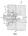
- FIG. 5 is a cut away view of an MASD 50 according to the third embodiment in a flow disabled position. In this position, the shut off body 32 acts at the outlet cover. The shut off body 32 is made to be moved while the nozzle body 12 is made to be stationary. While the third embodiment may be used in a hot runner manifold assembly, FIG. 5 depicts the third embodiment instilled in a stationary mold 58 , and the hot runner assembly (while not depicted) is connected to the nozzle body 12 .
- the MASD 50 includes a stop 52 which is formed to fit within a cavity 59 defined by the stationary mold 58 .
- a spring 54 is disposed between the stop 52 and the shut off body 32 .
- the moving side of the mold 60 is made to move by way of an actuated mold clamp (not depicted) and thereby the mold moving side 60 becomes offset from the stationary mold 58 , and also becomes offset or removed from the shut off body 32 .
- the spring 54 urges the shut off body 32 to move towards the removed mold portion 60 .
- a portion of the moved shut off body 32 now covers the outlet 15 , and the covered outlet 15 disables or blocks flow of the MAS disposed within the passageway 14 .
- the shut off body 32 moves in response to movement of the moving mold portion 60 moving away from the stationary mold 58 so that the moved shut off body 32 covers the outlet 15 .
- a heater 56 may be installed on the nozzle body 12 while another heater 34 may be installed on the shut off body 32 .
- the shut off body 32 presents an outlet cover surface which interacts with the outlet 15 .
- FIG. 6 is the cut away view of the MASD 50 of FIG. 5 in a flow enabled position.
- the shut off body 32 moves in response to the mold half 60 moving and abutting against the shut off body 32 .
- the moved shut off body 32 becomes offset from the outlet 15 so that the MAS may flow 24 from the uncovered outlet 15 .
- the moving mold 60 is made to move and push against the shut off body 32 , and in turn the shut off body 32 is displaced towards the stop 52 (and the spring 54 becomes depressed).
- a mold cavity 62 becomes lined up with the passageway 22 of the shut-off body 32 .
- the shut off body no longer covers the outlet 15 and the MAS contained within the outlet 15 may flow 24 freely without restriction.
- FIG. 7 shows is a cut away view of a MASD 70 according to the fourth embodiment in a flow disabled position.
- the MASD 70 includes an outlet cover which is indicated as a shut off body 72 which can also be called a stem.
- the nozzle body 12 defines a cavity 74 therein for slidably receiving the shut off body 72 therein.
- the shut off body 72 is slidable within the cavity 72 so as to alternately cover and uncover the outlet 15 .
- the nozzle body 12 also defines another passageway 78 that extends from the passageway 74 towards the outer edge of the nozzle body 12 .
- Disposed within the passageway 78 is a retaining rod 76 which connects to the shut off body 72 .
- the retaining rod 76 is externally actuated by mechanisms which are not depicted.
- the other end (not depicted) of the retaining rod 76 may be attached to a hydraulic, a pneumatic, an electric or a mechanic actuation assembly.
- the rod 76 when actuated, may move the shut off body 72 between a outlet closed and an outlet opened position.
- the actuation of the shut off body 72 is not made dependent directly on the operation of the mold assembly, but may be indirectly dependent on the operation of the mold assembly by way of the actuation mechanisms acting as an intermediary actuations structure.
- the mold assembly may operate directly on the actuations mechanisms which in turn actuate the rod 76 .
- FIG. 8 is the cut away view of the MASD of FIG. 7 in a flow enabled position, in which the shut off body 72 is retracted (by way of the rod 76 ) away from the outlet 15 so as to uncover the outlet 15 .
Landscapes
- Engineering & Computer Science (AREA)
- Mechanical Engineering (AREA)
- Manufacturing & Machinery (AREA)
- Moulds For Moulding Plastics Or The Like (AREA)
- Coating Apparatus (AREA)
- Injection Moulding Of Plastics Or The Like (AREA)
- Casting Devices For Molds (AREA)
- Manufacture And Refinement Of Metals (AREA)
- Vending Machines For Individual Products (AREA)
- Superconductors And Manufacturing Methods Therefor (AREA)
Priority Applications (16)
| Application Number | Priority Date | Filing Date | Title |
|---|---|---|---|
| US11/120,223 US7341094B2 (en) | 2005-05-02 | 2005-05-02 | Metallic alloy slurry dispenser |
| JP2008509273A JP5121701B2 (ja) | 2005-05-02 | 2006-04-05 | 金属合金スラリー吐出装置 |
| BRPI0610109-7A BRPI0610109A2 (pt) | 2005-05-02 | 2006-04-05 | distribuidor de lama de liga metálica |
| MX2007013608A MX2007013608A (es) | 2005-05-02 | 2006-04-05 | Distribuidor de suspension de aleacion metalica. |
| AT06721780T ATE473822T1 (de) | 2005-05-02 | 2006-04-05 | Zufuervorrichtung fuer thixotrope metall- legierungen |
| EP06721780A EP1896205B1 (en) | 2005-05-02 | 2006-04-05 | A metallic alloy slurry dispenser |
| CN2006800151819A CN101663113B (zh) | 2005-05-02 | 2006-04-05 | 金属合金浆料分配器 |
| AU2006243698A AU2006243698B2 (en) | 2005-05-02 | 2006-04-05 | A metallic alloy slurry dispenser |
| KR1020077028032A KR100977661B1 (ko) | 2005-05-02 | 2006-04-05 | 금속 합금 슬러리 분배기 |
| PCT/CA2006/000527 WO2006116838A2 (en) | 2005-05-02 | 2006-04-05 | A metallic alloy slurry dispenser |
| DE602006015469T DE602006015469D1 (de) | 2005-05-02 | 2006-04-05 | Zufuervorrichtung fuer thixotrope metall-legierungen |
| RU2007144611/02A RU2371281C2 (ru) | 2005-05-02 | 2006-04-05 | Дозирующее устройство суспензии металлического сплава |
| CA2605263A CA2605263C (en) | 2005-05-02 | 2006-04-05 | A metallic alloy slurry dispenser |
| TW095114371A TWI290497B (en) | 2005-05-02 | 2006-04-21 | A metallic alloy slurry dispenser |
| US11/781,408 US20080011448A1 (en) | 2005-05-02 | 2007-07-23 | Metallic Alloy Slurry Dispenser |
| US11/781,401 US20080011447A1 (en) | 2005-05-02 | 2007-07-23 | Metallic Alloy Slurry Dispenser |
Applications Claiming Priority (1)
| Application Number | Priority Date | Filing Date | Title |
|---|---|---|---|
| US11/120,223 US7341094B2 (en) | 2005-05-02 | 2005-05-02 | Metallic alloy slurry dispenser |
Related Child Applications (2)
| Application Number | Title | Priority Date | Filing Date |
|---|---|---|---|
| US11/781,401 Division US20080011447A1 (en) | 2005-05-02 | 2007-07-23 | Metallic Alloy Slurry Dispenser |
| US11/781,408 Division US20080011448A1 (en) | 2005-05-02 | 2007-07-23 | Metallic Alloy Slurry Dispenser |
Publications (2)
| Publication Number | Publication Date |
|---|---|
| US20060243416A1 US20060243416A1 (en) | 2006-11-02 |
| US7341094B2 true US7341094B2 (en) | 2008-03-11 |
Family
ID=37233303
Family Applications (3)
| Application Number | Title | Priority Date | Filing Date |
|---|---|---|---|
| US11/120,223 Expired - Fee Related US7341094B2 (en) | 2005-05-02 | 2005-05-02 | Metallic alloy slurry dispenser |
| US11/781,408 Abandoned US20080011448A1 (en) | 2005-05-02 | 2007-07-23 | Metallic Alloy Slurry Dispenser |
| US11/781,401 Abandoned US20080011447A1 (en) | 2005-05-02 | 2007-07-23 | Metallic Alloy Slurry Dispenser |
Family Applications After (2)
| Application Number | Title | Priority Date | Filing Date |
|---|---|---|---|
| US11/781,408 Abandoned US20080011448A1 (en) | 2005-05-02 | 2007-07-23 | Metallic Alloy Slurry Dispenser |
| US11/781,401 Abandoned US20080011447A1 (en) | 2005-05-02 | 2007-07-23 | Metallic Alloy Slurry Dispenser |
Country Status (14)
| Country | Link |
|---|---|
| US (3) | US7341094B2 (enExample) |
| EP (1) | EP1896205B1 (enExample) |
| JP (1) | JP5121701B2 (enExample) |
| KR (1) | KR100977661B1 (enExample) |
| CN (1) | CN101663113B (enExample) |
| AT (1) | ATE473822T1 (enExample) |
| AU (1) | AU2006243698B2 (enExample) |
| BR (1) | BRPI0610109A2 (enExample) |
| CA (1) | CA2605263C (enExample) |
| DE (1) | DE602006015469D1 (enExample) |
| MX (1) | MX2007013608A (enExample) |
| RU (1) | RU2371281C2 (enExample) |
| TW (1) | TWI290497B (enExample) |
| WO (1) | WO2006116838A2 (enExample) |
Cited By (4)
| Publication number | Priority date | Publication date | Assignee | Title |
|---|---|---|---|---|
| US20090200706A1 (en) * | 2006-04-11 | 2009-08-13 | Michelin Recherche Et Technique S.A. | Method and Device for Moulding Elastomeric Objects |
| WO2011054098A1 (en) * | 2009-11-06 | 2011-05-12 | National Research Council Of Canada | Feeding system for semi-solid metal injection |
| US20110186260A1 (en) * | 2010-01-29 | 2011-08-04 | Chang-Qing Zheng | Thixotropic Injector with Improved Annular Trap |
| CN109332641A (zh) * | 2018-09-30 | 2019-02-15 | 东莞市天禹五金科技有限公司 | 一种连接器外壳的生产模具及其生产工艺 |
Families Citing this family (10)
| Publication number | Priority date | Publication date | Assignee | Title |
|---|---|---|---|---|
| US20070131375A1 (en) * | 2005-12-09 | 2007-06-14 | Husky Injection Molding Systems Ltd. | Thixo-molding shot located downstream of blockage |
| CA2628504C (en) | 2007-04-06 | 2015-05-26 | Ashley Stone | Device for casting |
| US20100032123A1 (en) * | 2008-08-05 | 2010-02-11 | Ratte Robert W | Molding of die-cast product and method of |
| CN102092118B (zh) * | 2010-12-22 | 2013-07-17 | 吉林大学珠海学院 | 弹簧滑阀式喷嘴装置 |
| AT517240B1 (de) * | 2015-06-05 | 2018-04-15 | Ltc Gmbh | Barrel für eine Thixomoldingvorrichtung |
| JP6845612B2 (ja) * | 2016-03-07 | 2021-03-17 | 中村留精密工業株式会社 | 工作機械における機械精度の測定方法及び装置 |
| CN105880540A (zh) * | 2016-06-23 | 2016-08-24 | 吴江市液铸液压件铸造有限公司 | 用于液铸的分配器的冷却器 |
| CN107020363A (zh) * | 2017-05-05 | 2017-08-08 | 广东鸿图武汉压铸有限公司 | 一种整体式压铸模具浇口套 |
| CN109954858A (zh) * | 2019-04-17 | 2019-07-02 | 昆明理工大学 | 一种半固态制浆成形一体化方法 |
| US11883879B1 (en) * | 2022-09-07 | 2024-01-30 | Additive Technologies, LLC | System and method for controlling flow through a 3D printer |
Citations (16)
| Publication number | Priority date | Publication date | Assignee | Title |
|---|---|---|---|---|
| US3401426A (en) | 1966-05-31 | 1968-09-17 | New Britain Machine Co | Plastic injection molding machine |
| US4386903A (en) | 1981-05-01 | 1983-06-07 | Husky Injection Molding Systems Ltd. | Injection-molding machine with hydraulic mold clamping |
| US4678427A (en) | 1985-11-04 | 1987-07-07 | Husky Injection Molding System Ltd. | Automatic shut off nozzle for plastic extruder |
| WO1990009251A1 (en) | 1989-02-10 | 1990-08-23 | The Dow Chemical Company | Method and apparatus for the injection molding of metal alloys |
| EP0388242A2 (en) | 1989-03-17 | 1990-09-19 | Axiomatics Corporation | Heater device |
| US5785915A (en) | 1996-09-13 | 1998-07-28 | Osuna-Diaz; Jesus M. | Injection molding with annular gate and sleeve shutoff valve |
| US5960854A (en) | 1995-08-24 | 1999-10-05 | Oskar Frech Gmbh & Co. | Hot chamber die-casting machine |
| US5975127A (en) | 1996-02-28 | 1999-11-02 | Dray; R. F. | Shut-off valve |
| US6027328A (en) | 1996-02-26 | 2000-02-22 | Herbst; Richard | Apparatus for injection-molding plastic material items |
| US6203311B1 (en) | 1998-05-04 | 2001-03-20 | Robert F. Dray | Sliding ring non-return valve |
| US6230786B1 (en) * | 1998-05-26 | 2001-05-15 | Shin-Ei Die Casting Ind. Co., Ltd. | Automatic molten metal supply and injection device |
| US20010015272A1 (en) | 1998-03-31 | 2001-08-23 | Kaname Kono | Method and apparatus for manufacturing metallic parts by fine die casting |
| US6355197B1 (en) | 1997-03-20 | 2002-03-12 | Husky Injection Molding Systems Ltd. | Process and apparatus for forming plastic articles |
| US6357511B1 (en) | 2000-10-26 | 2002-03-19 | Husky Injection Molding Systems, Ltd. | Injection nozzle for a metallic material injection-molding machine |
| US6533021B1 (en) * | 1999-02-10 | 2003-03-18 | Ju-Oh Inc. | Mold for hot-runner injection molding machine and method for manufacturing the same |
| US7284978B2 (en) * | 2005-06-30 | 2007-10-23 | Husky Injection Molding Systems Ltd. | Brake for molding machine valve |
Family Cites Families (8)
| Publication number | Priority date | Publication date | Assignee | Title |
|---|---|---|---|---|
| DE19548687B4 (de) * | 1995-12-23 | 2004-01-08 | EWIKON Heißkanalsysteme GmbH & Co KG | Beheizte Nadelverschlußdüse |
| DE19615029C2 (de) * | 1996-02-26 | 1998-07-02 | Richard Herbst | Werkzeug zum Spritzgießen von Smart Cards |
| JP3329651B2 (ja) * | 1996-03-07 | 2002-09-30 | 株式会社日本製鋼所 | 金属の液相射出成形法 |
| US5928578A (en) * | 1997-03-26 | 1999-07-27 | Avalon Imaging, Inc. | Skip-eject system for injection molding machines |
| JP2000326062A (ja) * | 1999-05-21 | 2000-11-28 | Kobe Steel Ltd | 軽合金の射出成形方法及び装置とこれに用いるノズル |
| JP2002347084A (ja) * | 2001-05-23 | 2002-12-04 | Esuipi Kk | 射出成形用ホットランナ金型装置 |
| DE10354456B4 (de) * | 2002-11-21 | 2016-10-13 | Mold-Masters (2007) Limited | Düse mit einer Spitze, einem die Spitze umgebenden Teil und einem Positionierteil und Spritzgießvorrichtung mit der Düse |
| AU2003208219B9 (en) * | 2003-03-06 | 2007-04-26 | Husky Injection Molding Systems Ltd. | Sprue apparatus |
-
2005
- 2005-05-02 US US11/120,223 patent/US7341094B2/en not_active Expired - Fee Related
-
2006
- 2006-04-05 DE DE602006015469T patent/DE602006015469D1/de active Active
- 2006-04-05 JP JP2008509273A patent/JP5121701B2/ja not_active Expired - Fee Related
- 2006-04-05 RU RU2007144611/02A patent/RU2371281C2/ru not_active IP Right Cessation
- 2006-04-05 KR KR1020077028032A patent/KR100977661B1/ko not_active Expired - Fee Related
- 2006-04-05 AU AU2006243698A patent/AU2006243698B2/en not_active Ceased
- 2006-04-05 EP EP06721780A patent/EP1896205B1/en not_active Not-in-force
- 2006-04-05 WO PCT/CA2006/000527 patent/WO2006116838A2/en not_active Ceased
- 2006-04-05 AT AT06721780T patent/ATE473822T1/de not_active IP Right Cessation
- 2006-04-05 CN CN2006800151819A patent/CN101663113B/zh not_active Expired - Fee Related
- 2006-04-05 BR BRPI0610109-7A patent/BRPI0610109A2/pt not_active IP Right Cessation
- 2006-04-05 CA CA2605263A patent/CA2605263C/en not_active Expired - Fee Related
- 2006-04-05 MX MX2007013608A patent/MX2007013608A/es active IP Right Grant
- 2006-04-21 TW TW095114371A patent/TWI290497B/zh not_active IP Right Cessation
-
2007
- 2007-07-23 US US11/781,408 patent/US20080011448A1/en not_active Abandoned
- 2007-07-23 US US11/781,401 patent/US20080011447A1/en not_active Abandoned
Patent Citations (16)
| Publication number | Priority date | Publication date | Assignee | Title |
|---|---|---|---|---|
| US3401426A (en) | 1966-05-31 | 1968-09-17 | New Britain Machine Co | Plastic injection molding machine |
| US4386903A (en) | 1981-05-01 | 1983-06-07 | Husky Injection Molding Systems Ltd. | Injection-molding machine with hydraulic mold clamping |
| US4678427A (en) | 1985-11-04 | 1987-07-07 | Husky Injection Molding System Ltd. | Automatic shut off nozzle for plastic extruder |
| WO1990009251A1 (en) | 1989-02-10 | 1990-08-23 | The Dow Chemical Company | Method and apparatus for the injection molding of metal alloys |
| EP0388242A2 (en) | 1989-03-17 | 1990-09-19 | Axiomatics Corporation | Heater device |
| US5960854A (en) | 1995-08-24 | 1999-10-05 | Oskar Frech Gmbh & Co. | Hot chamber die-casting machine |
| US6027328A (en) | 1996-02-26 | 2000-02-22 | Herbst; Richard | Apparatus for injection-molding plastic material items |
| US5975127A (en) | 1996-02-28 | 1999-11-02 | Dray; R. F. | Shut-off valve |
| US5785915A (en) | 1996-09-13 | 1998-07-28 | Osuna-Diaz; Jesus M. | Injection molding with annular gate and sleeve shutoff valve |
| US6355197B1 (en) | 1997-03-20 | 2002-03-12 | Husky Injection Molding Systems Ltd. | Process and apparatus for forming plastic articles |
| US20010015272A1 (en) | 1998-03-31 | 2001-08-23 | Kaname Kono | Method and apparatus for manufacturing metallic parts by fine die casting |
| US6203311B1 (en) | 1998-05-04 | 2001-03-20 | Robert F. Dray | Sliding ring non-return valve |
| US6230786B1 (en) * | 1998-05-26 | 2001-05-15 | Shin-Ei Die Casting Ind. Co., Ltd. | Automatic molten metal supply and injection device |
| US6533021B1 (en) * | 1999-02-10 | 2003-03-18 | Ju-Oh Inc. | Mold for hot-runner injection molding machine and method for manufacturing the same |
| US6357511B1 (en) | 2000-10-26 | 2002-03-19 | Husky Injection Molding Systems, Ltd. | Injection nozzle for a metallic material injection-molding machine |
| US7284978B2 (en) * | 2005-06-30 | 2007-10-23 | Husky Injection Molding Systems Ltd. | Brake for molding machine valve |
Cited By (7)
| Publication number | Priority date | Publication date | Assignee | Title |
|---|---|---|---|---|
| US20090200706A1 (en) * | 2006-04-11 | 2009-08-13 | Michelin Recherche Et Technique S.A. | Method and Device for Moulding Elastomeric Objects |
| WO2011054098A1 (en) * | 2009-11-06 | 2011-05-12 | National Research Council Of Canada | Feeding system for semi-solid metal injection |
| US20110108231A1 (en) * | 2009-11-06 | 2011-05-12 | Chang-Qing Zheng | Feeding System for Semi-Solid Metal Injection |
| US8327914B2 (en) * | 2009-11-06 | 2012-12-11 | National Research Council Of Canada | Feeding system for semi-solid metal injection |
| US20110186260A1 (en) * | 2010-01-29 | 2011-08-04 | Chang-Qing Zheng | Thixotropic Injector with Improved Annular Trap |
| US8376026B2 (en) * | 2010-01-29 | 2013-02-19 | National Research Council Of Canada | Thixotropic injector with improved annular trap |
| CN109332641A (zh) * | 2018-09-30 | 2019-02-15 | 东莞市天禹五金科技有限公司 | 一种连接器外壳的生产模具及其生产工艺 |
Also Published As
| Publication number | Publication date |
|---|---|
| ATE473822T1 (de) | 2010-07-15 |
| AU2006243698A1 (en) | 2006-11-09 |
| JP5121701B2 (ja) | 2013-01-16 |
| WO2006116838A2 (en) | 2006-11-09 |
| US20060243416A1 (en) | 2006-11-02 |
| CA2605263C (en) | 2010-03-30 |
| EP1896205B1 (en) | 2010-07-14 |
| KR100977661B1 (ko) | 2010-08-24 |
| AU2006243698B2 (en) | 2009-08-20 |
| BRPI0610109A2 (pt) | 2010-05-25 |
| EP1896205A4 (en) | 2009-03-04 |
| MX2007013608A (es) | 2008-01-24 |
| US20080011448A1 (en) | 2008-01-17 |
| US20080011447A1 (en) | 2008-01-17 |
| EP1896205A2 (en) | 2008-03-12 |
| CN101663113A (zh) | 2010-03-03 |
| JP2008540128A (ja) | 2008-11-20 |
| RU2007144611A (ru) | 2009-06-10 |
| CA2605263A1 (en) | 2006-11-09 |
| TW200702081A (en) | 2007-01-16 |
| RU2371281C2 (ru) | 2009-10-27 |
| DE602006015469D1 (de) | 2010-08-26 |
| KR20080007274A (ko) | 2008-01-17 |
| TWI290497B (en) | 2007-12-01 |
| CN101663113B (zh) | 2012-07-25 |
Similar Documents
| Publication | Publication Date | Title |
|---|---|---|
| US20080011447A1 (en) | Metallic Alloy Slurry Dispenser | |
| CA2498897A1 (en) | Metering device for a nozzle of an injection molding apparatus | |
| EP0452611B1 (en) | Injection nozzle with a reciprocating heated probe | |
| US6880614B2 (en) | Vertical injection machine using three chambers | |
| JP2008540128A5 (enExample) | ||
| US4828480A (en) | Sprue bushing with automatically activated gate | |
| US20060159798A1 (en) | Method for producing mould parts by injection and plugged needle nozzle for an injection mould | |
| EP1934005B1 (de) | Druckgiessverfahren | |
| JP3794549B2 (ja) | 金属製品成形用金型における粉体離型剤の塗布方法および金属製品成形用金型 | |
| JPH09155526A (ja) | 金属材料の射出装置 | |
| US5884687A (en) | Heated-chamber die-casting apparatus | |
| EP1976654B1 (en) | Thixo-molding shot located downstream of blockage | |
| CA2658574A1 (en) | Cooling structure of metal-molding system for shot located downstream of blockage | |
| JP2004249344A (ja) | 軽合金の射出成形方法及び射出成形装置 | |
| JP4359826B2 (ja) | 金属材料成形装置 | |
| SU234644A1 (ru) | Крупногабаритных изделий | |
| JPH04220153A (ja) | 射出成形方法及び射出成形機 | |
| JP2004243366A (ja) | ダイカスト装置 | |
| JP2010188409A (ja) | 軽金属射出成形機の射出装置 | |
| JPH0363455B2 (enExample) | ||
| JPS63158219A (ja) | 合成樹脂射出成形システムにおける流量制御装置 | |
| JPH08127049A (ja) | 樹脂成形機 | |
| PL190635B1 (pl) | Sposób ciśnieniowego odlewania stopu magnezu i układ przepływu metalu w urządzeniu do ciśnieniowegoodlewania stopu magnezu |
Legal Events
| Date | Code | Title | Description |
|---|---|---|---|
| AS | Assignment |
Owner name: HUSKY INJECTION MOLDING SYSTEMS LTD., CANADA Free format text: ASSIGNMENT OF ASSIGNORS INTEREST;ASSIGNOR:MANDA, JAN MARIUS;REEL/FRAME:016534/0408 Effective date: 20050428 |
|
| AS | Assignment |
Owner name: ROYAL BANK OF CANADA, CANADA Free format text: SECURITY AGREEMENT;ASSIGNOR:HUSKY INJECTION MOLDING SYSTEMS LTD.;REEL/FRAME:020431/0495 Effective date: 20071213 Owner name: ROYAL BANK OF CANADA,CANADA Free format text: SECURITY AGREEMENT;ASSIGNOR:HUSKY INJECTION MOLDING SYSTEMS LTD.;REEL/FRAME:020431/0495 Effective date: 20071213 |
|
| FPAY | Fee payment |
Year of fee payment: 4 |
|
| AS | Assignment |
Owner name: HUSKY INJECTION MOLDING SYSTEMS LTD., CANADA Free format text: RELEASE OF SECURITY AGREEMENT;ASSIGNOR:ROYAL BANK OF CANADA;REEL/FRAME:026647/0595 Effective date: 20110630 |
|
| REMI | Maintenance fee reminder mailed | ||
| LAPS | Lapse for failure to pay maintenance fees | ||
| STCH | Information on status: patent discontinuation |
Free format text: PATENT EXPIRED DUE TO NONPAYMENT OF MAINTENANCE FEES UNDER 37 CFR 1.362 |
|
| FP | Lapsed due to failure to pay maintenance fee |
Effective date: 20160311 |