US7188046B2 - Form measuring device, form measuring method, form analysis device, form analysis program, and recording medium storing the program - Google Patents
Form measuring device, form measuring method, form analysis device, form analysis program, and recording medium storing the program Download PDFInfo
- Publication number
- US7188046B2 US7188046B2 US10/936,509 US93650904A US7188046B2 US 7188046 B2 US7188046 B2 US 7188046B2 US 93650904 A US93650904 A US 93650904A US 7188046 B2 US7188046 B2 US 7188046B2
- Authority
- US
- United States
- Prior art keywords
- measured
- section
- measuring
- pairs
- pair
- Prior art date
- Legal status (The legal status is an assumption and is not a legal conclusion. Google has not performed a legal analysis and makes no representation as to the accuracy of the status listed.)
- Active, expires
Links
Images


Classifications
-
- G—PHYSICS
- G01—MEASURING; TESTING
- G01B—MEASURING LENGTH, THICKNESS OR SIMILAR LINEAR DIMENSIONS; MEASURING ANGLES; MEASURING AREAS; MEASURING IRREGULARITIES OF SURFACES OR CONTOURS
- G01B21/00—Measuring arrangements or details thereof, where the measuring technique is not covered by the other groups of this subclass, unspecified or not relevant
- G01B21/02—Measuring arrangements or details thereof, where the measuring technique is not covered by the other groups of this subclass, unspecified or not relevant for measuring length, width, or thickness
- G01B21/08—Measuring arrangements or details thereof, where the measuring technique is not covered by the other groups of this subclass, unspecified or not relevant for measuring length, width, or thickness for measuring thickness
-
- G—PHYSICS
- G06—COMPUTING; CALCULATING OR COUNTING
- G06T—IMAGE DATA PROCESSING OR GENERATION, IN GENERAL
- G06T7/00—Image analysis
- G06T7/50—Depth or shape recovery
- G06T7/55—Depth or shape recovery from multiple images
- G06T7/564—Depth or shape recovery from multiple images from contours
Definitions
- the present invention relates to a form measuring device, a form measuring method, a form analysis device, a form analysis program, and a recording medium storing the program. More specifically, this invention relates to a form measuring device capable of accurately measuring irregularities or angular displacements of each surface of a flat polyhedron, or a form measuring device capable of analytically obtaining a form of a surface.
- straightness of each edge has been measured, for instance, by scanning an object edge to be measured with a detector (such as for instance, an electrical micrometer) moving along a straightedge ruler to detect displacement from the straightedge ruler as a reference for straightness.
- a detector such as for instance, an electrical micrometer
- perpendicularity has been measured by placing the right-angled square on and inside reference scales positioned with right angles to each other and measuring a distance from the reference scales to each edge of the right-angled square (Refer to, for instance, Document 1: Japanese Patent Laid-Open Publication No. HEI 9-2433351).
- an optical interferometer 100 for measuring the distance before two surfaces comprises a light source 100 as a laser beam source, a CCD camera as a photographing device, and a half-mirror 103 provided on the light axis.
- a reference object 201 having a reference surface D, which has been proposed into a completely flat surface, and an object to be measured 202 having a surface to be measured E are provided on the light axis of the optical interferometer 100 in the state in which the reference surface D and the surface to be measured E are positioned face to face substantially in parallel to each other.
- the reference surface D and the surface to be measured E are positioned vertically to the incident light from the light source 101 .
- Both of reference object 201 and the object to be measured 202 are made of transparent material such as glass.
- the present invention can be utilized to obtain an accurate result of measurement by using a measuring section, a function value setting section, a simultaneous equation deriving section, and a simultaneous equation processing section to mutually measure positions of an object to be measured and apply the measurement data to the simultaneous equation to obtain a solution
- a specific reference for measurement such as a reference scale or a reference surface in this invention.
- the form measuring device comprises a measuring section having two straightedge rules for obtaining measurement data obtained by combining the straightedge rules with an object to be measured, which is a flat polyhedron, so as to oppose to each other, and measuring the spaces therebetween at a plurality of sampling points; a function value setting section for setting form-function values, which indicates distances from reference lines set for each edge of the object to be measured as well as for the straightedge rule to the straightedge rules and the edges of said object to be measured at sampling points, and angular function values which indicates internal angles of the object to be measured and an angle formed by the straightedge rules; a simultaneous equation deriving section for deriving simultaneous equations for pairs of the straightedge rule and each edge of the object to be measured using an angle formed with reference lines for the two straightedge rules and each internal angle of the object to be measured and assuming that a distance from the straightedge rule to the edge of the object to be measured is equal to a value obtained by adding the form-function value to a distance from the reference line of the straightedge
- the reference line is, for ice, a least-squares line obtained by subjecting a measured surface of the straightedge rule and a measured surface along each edge of the object to be measured to the processing for least-squares recursion respectively.
- the form measuring device comprises a measuring section for combining two out of three surfaces to be measured substantially in parallel to each other as a pair in a specific pattern and respectively measuring a space therebetween at a plurality of sampling points, a function value setting section for setting form-function values, which indicates distances from reference planes respectively set for each of the surfaces to be measured to the surfaces to be measured a simultaneous equation deriving section for deriving simultaneous equations for a pair of the surfaces to be measured having a specific pattern assuming that a surface spacing between the surfaces to be measured placed in the specific pattern is equal to the sum of a distance from the reference plane to the surface to be measured and a distance between the reference planes set for the surfaces to be measured paired with each other, and a simultaneous equation processing section for processing the derived simultaneous equations.
- surfaces to be measured are arranged as pairs each in a specific pattern, and spaces therebetween are measured at a plurality of sampling points for each pair with a specific pattern. Then by deriving and solving equations satisfying the spaces between surfaces to be measured and form-function values, the form-function values can be obtained. Then a form of each surface to be measured can be obtained as a residual from the reference plane.
- a form of a surface to be measured can be obtained by processing measurement data obtained by measuring surface spacing of each pair of surfaces to be measured each with the flatness still known, so that a form of an surfaces to be measured can be obtained without using a reference surface.
- the met section preferably measures He spacing for the surface to be measured for five pairs which are: three pairs formed by combining two out of the three surfaces to be measured substantially in parallel to each other, one pair formed by rotating a surface to be measured of one of the above-mentioned three pairs by 90 degrees against the other surface, and another pair formed by displacing a surface to be measured of one of the above-mentioned three pairs in parallel to the other surface.
- measuring areas can be correlated to each other in each pair of surfaces to be measured, so that form-function values, which indicates a form of an surfaces to be measured, can be obtained by solving simultaneous equations. For instance, with only three pairs, each consisting of two surfaces to be measured positioned substantially in parallel to each other, corresponding areas are present only in the center line, so that a form of the surface can not be obtained by solving simultaneous equations, but when a pair in which one of the surfaces to be measured is relatively rotated and a pair in which one of the surfaces to be measured is translated are added, sufficient conditions are provided to correlate measuring areas to each other for solving simultaneous equations.
- FIG. 1 is a view showing configuration of a form measuring device according to a first embodiment of the present invention
- FIG. 2 is a view showing three surfaces to be measured
- FIG. 3 is a view showing the state in which a reference plane is set on a surface to be measured in the first embodiment above;
- FIG. 4 is a view showing the state in which surfaces to be measured are placed face to face substantially in parallel to each other in the first embodiment
- FIG. 5 is a view showing a relation between a surface spacing and a form-function value in the first embodiment
- FIG. 6 is a view showing the state in which a first surface to be measured A and a second surface to be measure B are placed at positions opposed to each other in the first embodiment;
- FIG. 7 is a view showing the state in which the second surface to be measured B and a third surface to be measured C are placed at positions opposed to each other in the first embodiment;
- FIG. 8 is a view showing the state in which the third surface to be measured C and the first surface to be measured A are placed at positions opposed to each other in the first embodiment;
- FIG. 9 is a view showing the state in which the second surface to be measured B is rotated by 90 degrees from the pattern shown in FIG. 6 showing the state in which the first surface to be measured A and the second surface to be measured B are placed at positions opposed to each other in the first embodiment;
- FIG. 10 is a view showing the state in which the second surface to be measured B is displaced in the X-axial direction from the pattern shown in FIG. 6 showing the state in which the first surface to be measured A and the second surface to be measure B are placed at positions opposed to each other in the first embodiment;
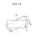
- FIG. 11 is a view showing the state in which the second surface to be measured B is rotate by the angle ⁇ from the pattern shown in FIG. 6 showing the state in which the first surface to be measured A and the second surface to be measured B are placed at positions opposed to each other in Variant 1 of the form measuring device according to the present invention;
- FIG. 12 is a view showing the case in which an surface to be measured is a rectangle in the variant 1 above;
- FIG. 13 is a view showing the state in which surfaces to be measured are placed opposed to each other with both of the top surfaces facing outward;
- FIG. 14 is a view showing the state in which an surface spacing is measured with an electrical micrometer
- FIG. 15 is a view showing the state in which an optical interferometer is used in a method of measuring a form of a surface to be measured based on the conventional technology
- FIG. 16 is a view showing a form measuring device according to a second embodiment of the present invention.
- FIG. 17 is a view showing configuration of an analyzing section in the second embodiment
- FIG. 18 is a view showing measurement data in the second embodiment
- FIG. 19 is a view showing a from function value in the second embodiment
- FIG. 20 is a view showing an angle-function value in the second embodiment.
- FIG. 21 is a view showing a reference line, a form-function, and an angle-function.
- FIG. 1 Configuration of a form measuring device according to a first embodiment of the present invention is shown in FIG. 1 .
- the first embodiment relates to solution to aforesaid second object of the present invention.
- the form measuring device 1 comprises a measuring section 2 , an analyzing section (form analyzing device) 3 , and an output section 4 .
- the measuring section 2 measures a space m between surfaces to be measured at each sampling point in the state in which two out of three objects to be measured as shown in FIG. 2 are combined as a pair in a specific pattern.
- first object to be measured 51 a first object to be measured 51
- second object to be measured 52 a second object to be measured 52
- third object to be measured 53 objects to be measured.
- the first object to be measured 51 , second object to be measured 52 , and third object to be measured 53 are formed with a light-transmissible material such as, for instance, glass.
- the first object to be measured 51 has a first surface to be measured A on one surface thereof.
- the second object to be measured 52 has a second surface to be measured B on one surface thereof.
- the third object to be measured 53 has a third surface to be measured C on one surface thereof.
- All of the first, second, and third surfaces to be measured A, B, C are surfaces each as an object to be measured, and all of the surfaces are processed into the substantially flat surface, but the flatness is unknown.
- the measuring section 2 may comprise an optical interferometer as described in Description of Related Art.
- an surface spacing m is measured in the state in which the three surfaces to be measured A to C are combined to each other in a specific pattern and the combination pattern is described hereinafter with reference to FIG. 6 to FIG. 10 .
- the analyzing section 3 comprises a measurement data storage section 31 , a function value setting section 32 , a basis function setting section 33 , an observation equation deriving section (simultaneous equation deriving section) 34 , and an computing processing section (simultaneous equation processing section) 35 .
- the analyzing section 3 comprises a central processing unit (CPU) 36 , and operations of the measurement data storage section 31 , function value setting section 32 , basis function setting section 33 , observation equation deriving section 34 , and computing processing section 35 are controlled by the CPU 36 via a bus 37 .
- CPU central processing unit
- the measurement data storage section 31 stores therein measurement data obtained in the measuring section 2 . Namely, the measurement data storage section 31 stored therein measurement data obtained by measuring surface spacing m between surfaces to be measured in the state where the surfaces to be measured A to C are combined as pairs each having a specific pattern at a plurality of sampling points.
- the function value setting section. 32 stored therein function values set as unknown parameters, which indicates forms of the surfaces to be measured A to C respectively.
- a reference plane R is virtually set for each of the surfaces to be measured as shown in FIG. 3 .
- the reference plane R is a virtual plane set substantially in parallel to each of the surfaces to be measured A to C, and for instance, a least square plane of a form or a plane passing through the highest three points is set as a reference plane.
- a residual (distance) d from the reference plane R to each of the surfaces to be measured A to C is set as a form-function value (function value setting step). Further the form-function value on a coordinate system set on each of the surfaces to be measured A to C is expressed as d (x, y).
- the basis function setting section 33 stores therein a basis function comprising a basis B (x, y) having a pair of elements linearly independent from each other.
- the basis B (x, y) is not limited to any specific function, but such functions as a spline function or Fourier series are available for this purpose.
- the observation equation deriving section 34 derives equations satisfied by the measurement data m (x, y) obtained in the measuring section 2 and the form-function value d (x, y) set in the function value setting section 32 .
- the direction in which the two surfaces get farther from each other is assumed as positive, but as for the residuals d A , d B , the direction in which the surface to be measured get farther from the reference plane is assumed as positive. Therefore the sign for the distance m between two surfaces is reverse to that for the residuals d A , d B .
- the second surface to be measured is reversed against the axis Y as a symmetry axis to position the second surface to be measured against the first surface to be measured, so that coordinate values of a point on the second surface to be measured corresponding to the point (x, y) on the first surface to be measured is ( ⁇ x, y).
- a distance between a first reference plane R A as a reference plane for the first surface to be measured A and a second reference plane R B as a reference plane for the second surface to be measured B is expressed as W 1 (x, y).
- a distance between surfaces to be measured is measured for each pair having a specific pattern in the measuring section 2 , so that a plurality of observation equations equal to a total number of measuring points at which measurement is performed with the specific pattern respectively are derived.
- the computing processing section 35 processes the equations derived in the observation equation deriving sections 34 .
- the residual d (x, y) is obtained, and thus a form of each surface to be measured is obtained as irregularity from the reference line.
- the surfaces to be measured A to C are positioned as pairs each having a specific pattern, and spaces between surfaces to be measured are measured at a plurality of sampling points for each pair (measuring step). Five patterns formed with pairs consisting two of the three surfaces to be measured A to C are shown in FIG. 6 to FIG. 10 .
- FIG. 6 to FIG. 8 show the cases in which two of the first to third surfaces to be measured A to C are combined face to face as a pair.
- FIG. 9 shows a case in which the second surface to be measured B is rotated by 90 degrees from the pattern shown in FIG. 6 in which the first surface to be measured A and the second surface to be measured B are positioned facing against each other.
- FIG. 10 is a pattern obtained by moving the second surface to be measured B in the X-axial direction from the pattern shown in FIG. 6 in which the first surface to be measured A and the second surface to be measured B are positioned facing against each other.
- An arrow shown on each surface to be measured in each figure indicates the Y-axial direction on the surface to be measured.
- the direction perpendicular to the Y-axial direction on each surface to be measured is the X-axial direction.
- the measuring section 2 measures spaces between surfaces to be measured for patterns shown in FIG. 6 to FIG. 10 at each sampling point.
- the measurement data obtained in the measuring section 2 is stored in the measurement data storage section 31 .
- observation equations are derived by the observation equation deriving section 34 .
- the residual d (form-function value) can be expressed as shown below. This indicates a form of a surface to be measured positioned in the upper side in each of FIG. 6 to FIG. 8 .
- the residual d (form-function value) can be expressed as shown below. This indicates a from of the second surface to be measured B positioned in the upper side in FIG. 9 .
- the residual d can be expressed as shown below. This indicates a from of the second surface to be measured B positioned in the upper side in FIG. 10 .
- the distance W (x, y) between reference planes is defined as shown below, wherein w k is a term indicating a relative posture of the reference plane.
- the computing processing section 35 obtains the coupling factor a i by solving the observation equation derived as described above (simultaneous equation processing step). In this step, it is required to add the conditions for deciding the relative posture w k of a reference plane, for instance, conditions defining three points through which the reference plane pass are provided for deciding a posture of the plane. Under the conditions, the coupling factor a i is obtained by the equation (12).
- a result of processing is outputted to the output section 4 .
- Such devices as a monitor or a printer may be used for this purpose so long as the device can output a result of processing
- Variant 1 of the form measuring device according to the present invention is described below.
- the basic configuration of Variant 1 is the same as that in the first embodiment, but Variant 1 is characterized in that measurement data for pairs, in each of which one surface to be measured is rotated by a given angle against the other surface to be measured, is used.
- FIG. 6 to FIG. 10 five patterns each comprising a pair of two out of three surfaces to be measured A to C are shown in FIG. 6 to FIG. 10 , and especially FIG. 9 shows a case in which the second surface to be measured B is rotated by 90 degrees from the pattern shown in FIG. 6 in which the first surface to be measured A and the second surface to be measured B are placed at positions opposed to each other.
- An equation corresponding to the observation equation expressed by the equation (9) can be obtained by using the equation (14) in place of the equation (4).
- Forms of the surfaces to be measured A to C can be obtained by solving the equation corresponding to the equation (12) using the form-function value d.
- Variant 2 of the form measuring device according to the present invention is described.
- the basic configuration of Variant 2 is the same as that in the first embodiment, but Variant 2 is characterized in that a form-function value is obtained by using simultaneous equations in place of a basis.
- identical sampling points are set in all of the pairs shown in FIG. 6 to FIG. 10 .
- an inter-plane distance is measured at each lattice point.
- the shift rate for the surface to be measured B shown in FIG. 10 is a rate to which a measuring point corresponds after shifted.
- shifting is performed by one lattice unit:
- the form-function value d can be obtained by solving the equation (15), and forms of the surfaces to be measured A to C can be obtained as irregularities from the reference planes.
- the overlaid area when the surface to be measured B is rotated by 90 degrees should preferably be sufficiently large.
- the surface to be measured should preferably be square or round.
- measuring section 2 assumes the use of the optical interferometer 100 , but it is needless to say, for instance, as shown in FIG. 14 , that a space between two planes may be measured with the electric micrometer 6 or the like.
- the black circle in FIG. 14 indicates a sampling point.
- each of the objects to be measured 51 to 53 is made of a transparent material, there is not any specific restriction over a material for and a form of the object to be measured.
- FIG. 16 shows configuration of a form measuring device according to a second embodiment of the present invention
- the second embodiment relates to solution to aforesaid first object of the present invention.
- a form measuring device 301 comprises two straightedge miles 321 , 322 and comprise a measuring section 302 for obtaining measurement data obtained by measuring spaces m between the straightedge rules 321 , 322 and four edges ( 351 to 354 ) of a object to be measured 305 in each of different pairs at a plurality of points, an analyzing section (a form analyzing device) 303 for analyzing a form of an object to be measured by processing the obtained measurement data, and an output section 304 for outputting a result of analysis.
- the measuring section 302 comprises the two straightedge rules 321 , 322 placed in the state in which extension lines from the rules cross each other at specific angles, a length measuring sensor 324 for measuring spaces between the object to be measured 305 , which is placed at positions when each of edges ( 351 to 354 ) thereof faces straightedge rules 321 , 322 , and the straightedge rules 321 , 322 at a plurality of points, and a moving mechanism (not shown) for moving the length measuring sensor 324 in the longitudinal directions of the straightedge rules 321 , 322 .
- the two straightedge rules 321 , 322 which arm placed with an angle(smaller than 180 degrees) formed thereby and sufficient for accommodating the object to be measured 305 therein.
- the two straightedge rules 321 , 322 are positioned with an angle equal to the maximum internal angle ( 355 to 358 ) of the object to be measured 305 . For instance, when the object to be measured 305 is a right-angled square, the two straightedge rules 321 , 322 are positioned so that extension lines thereof form a substantially right angle.
- Detected surfaces of the straightedge rules 321 , 322 facing toward the object to be measured 305 should preferably be machined to as much straight state as possible, but this measuring method is not affected by the machining errors in the straightedge rules 321 , 322 , so that the straightedge rules 321 , 322 are not always required to be machined to the completely straight state.
- the straightedge rules 321 , 322 are required to have corresponding points opposed to points on edges ( 351 to 354 ) of the object to be measured 305 , and therefore are required to have the length at least equal to or more than the longest edge of the object to be measured 305 .
- straightedge rules is described as a first straightedge rule 321 , and the other straightedge rule as a second straightedge rule 322 .
- the length measuring sensor 324 measures a space m between the straightedge rules 321 , 322 and the object to be measured 305 at a specified sampling pitch.
- the length measuring sensor 324 can move in the longitudinal direction of the straightedge rules 321 , 322 .
- the length measuring sensor 324 comprises a tubular main body section 325 provided movable in the longitudinal directions of the straightedge rules 321 , 322 , a first spindle 326 and a second spindle 327 provided movable in the contrary directions from the main body section 325 respectively, and a detecting section (not shown) for detecting a travel of each of the first spindle 326 and the second spindle 327 .
- Contactors 426 , 427 contacting the object to be measured are provided at tips of the first spindle 326 and the second spindle 327 .
- the length measuring sensor 324 directs the first spindle 326 toward the straightedge rule 321 ( 322 ) between the straight stale 321 , 322 and the object to be measured 305 , and also directs the second spindle 327 toward the object to be measured 305 .
- the first spindle 326 and the second spindle 327 are moved forward or backward according to irregularities on surfaces of the straightedge rules 321 , 322 as well as on the object to be measured 305 , and a distance m between the straightedge rules 321 , 322 and edges ( 351 to 354 ) of the object to be measured 305 is detected from the sum of total travels of the first spindle 326 and the second spindle 327 .
- the moving mechanism is not shown, and comprises, for instance, driving shafts provided along the straightedge rules 321 , 322 , and a slider capable of sliding on each of the driving shafts.
- the length measuring sensor 324 may be attached to the slider so that the length measuring sensor 324 can move together with the slider.
- the slider is preferably capable of setting the moving pitch according to a sampling pitch of the length measuring sensor 324 .
- a mount base machined into the substantially flat state for mounting the straightedge rules 321 , 322 and the object to be measured 305
- a positioning unit for deciding positions of the straightedge rules 321 , 322 and the object to be measured 305 .
- Any type of positioning unit may be employed such as a positioning pin projecting from the mount base or a positioning plate, and still further it is preferable that the positioning pin or the positioning place can move and also can be fixed at a given position.
- the analyzing section 303 comprises, as shown in FIG. 17 , a measurement data storage section 331 for storing therein measurement data obtained in the measuring section 302 , a function value setting section 332 for setting function values indicating forms of the straightedge rules 321 , 322 and the object to be measure 305 , a simultaneous equation deriving section 333 for deriving simultaneous equations indicating relations between the measurement data and the function values set therein, a simultaneous equation processing section 334 for solving the derived simultaneous equations and a central control unit (CPU) b 335 controlling operations of the analyzing section 303 .
- These measurement data storage section 331 , function value setting section 332 , simultaneous equation deriving section 333 , simultaneous equation processing section 334 , and CPU 335 are connected to each other though a bus 336 .
- the measurement data storage section 331 stores therein the measurement data obtained in the measuring section 302 , and for instance, stores therein a distance m (x i ) at each sampling point x i for a pair of each of the straightedge rules 321 , 322 and each of edges ( 351 to 354 ) of the object to be measured 305 .
- the function value setting section 332 stores therein function values set as unknown parameters indicating forms of the straightedge rules 321 , 322 , forms of the object to be measured 305 , internal angles of the object to be measured, and postures of the straightedge rules 321 , 322 as shown in FIG. 19 and FIG. 20 (function value setting step).
- reference lines (R 1 to R 6 ) for linearly regressing the edges to be detected as shown in FIG. 21 are virtually set. Further a residual (distance) from any of the reference lines (R 1 to R 6 ) set virtually to the detected surface is set as a form-function value.
- the reference lines R 1 to R 6 are, for instances least self-square straight lines.
- L 1 indicates a residual for the first straightedge rule 321 from the reference line R 1 and a form-function value L 1 (x i ) indicates a residual at the sampling point x i (Refer to FIG. 19 ).
- L 2 (x i ) indicates a residual for the second straight light 322 at the sampling point x i .
- S 1 indicates a residual for the first edge 351 of the object to be measured 305 from the reference line R 3
- S 1 (x i ) indicates a residual at the sampling point x i
- form-function values S 2 (x i ), S 3 (x i ), S 4 (x i ) . . . indicate residuals for the second edge 352 , third edge 353 , fourth edge 354 . . . of the object to be measured 305 respectively.
- Internal angles ( 355 to 358 ) of the object to be measured 305 as a polygon are off from 180 ⁇ (n ⁇ 2)/n, and the angular differences between these internal angles ( 355 to 358 ) and an internal angle of the regular polygon(having n angles) is set as an angle-function value.
- internal angles of a top plane of the object to be measured 305 are a first angle 355 , a second angle 356 , a third angle 357 , a fourth angle 358 . . .
- the angular differences of these internal angles from 180 ⁇ (n ⁇ 2)/n are set as ⁇ , ⁇ , ⁇ , ⁇ . . . respectively.
- the internal angles ( 355 to 358 ) of the object to be measured 305 are defined as those formed by the reference lines (R 3 to R 6 ) for the edges ( 351 to 354 ).
- the angle function-value is set as a deviation from 90 degrees. Namely, internal angles of a right-angled square are expressed as 90°+ ⁇ for the first angle ( 355 ), 90°+ ⁇ for the second angle ( 356 ). 90°+ ⁇ for the third angle, and 90°+ ⁇ for the fourth angle ( 358 ).
- a function value indicating postures of the two straightedge rules 321 , 322 is expressed as a difference from 180 ⁇ (n ⁇ 2)/n like in the case of the internal angles of the object to be measured 305 , and an angular difference of an angle formed by the reference lines R 1 , R 2 for the two straightedge rules 321 , 322 from 180 ⁇ (n ⁇ 2)/n is expressed as an angular-function value ⁇ .
- the internal angles ( 355 to 358 ) of the object to be measured 305 are expressed by these angle-function values ( ⁇ , ⁇ , ⁇ , ⁇ . . . ).
- the simultaneous equation deriving section 333 derives equations satisfied by the measurement data m (xi) obtained in the measuring section 302 as well as by the form-function values 1 (xi), S(xi) and the angle-function values ⁇ to ⁇ set in the function value setting section 332 (simultaneous equation deriving step).
- the process of deriving the equations set in the simultaneous equation deriving section 333 is briefly described below.
- m 22 ⁇ ( Xi ) L 2 ⁇ ( Xi ) + S 2 ⁇ ( Xi ) + D 22 ⁇ ( Xi ) ( 17 )
- m 12 ⁇ ( Xi ) L 1 ⁇ ( Xi ) + S 2 ⁇ ( Xi ) + D 12 ⁇ ( Xi ) ⁇ ⁇ ⁇ ( 18 )
- m 21 ⁇ ( Xi ) L 2 ⁇ ( Xi ) + S 1 ⁇ ( Xi ) + D 21 ⁇ ( Xi ) ( 19 )
- the distance D between the reference lines is expressed by a linear expression using the “u” and the “w”.
- the distance D 11 between the first reference line R 1 for the first straightedge rule 321 and the reference line R 3 for the first edge 351 is expressed by the following equation using the gradient u 11 and the segment w 11 :
- the distance D 22 between the reference line R 2 for the second straightedge rule 322 and the reference line R 4 for the second edge 352 is likely expressed by using the gradient u 22 and the segment w 22 , and the same is true also for other cases.
- D 22 ( Xi , 1 ) ⁇ ( U 22 W 12 ) ( 22 )
- D 12 ( Xi , 1 ) ⁇ ( U 12 W 12 ) ( 23 )
- D 21 ( Xi , 1 ) ⁇ ( U 21 W 21 ) ( 24 )
- D 5 ( Xi , 1 ) ⁇ ( U 5 W w ) ( 25 )
- a relation between the second straightedge rule 322 and an edge ( 351 to 354 ) of the object to be measured 305 is expressed with the relation between the first straightedge rule 321 and the edge ( 351 to 354 ) of the object to be measured 305 using an angle (angle-function value ⁇ ) formed by the reference lines R 1 , R 2 for the first straightedge rule 321 and the second straightedge rule 322 and each internal angle (angle-function value ⁇ , ⁇ , . . . ) of the object lo be measured 305 .
- a relation between the pair consisting of an edge of the object to be Measured 305 and the first straightedge rule 321 and the pair consisting of an edge adjoining that of the object to be measured 305 and the second straightedge rule 322 is in the state where a relative posture of one pair is expressed by a relative posture of another pair.
- U 23 U 12 ⁇ + ⁇ (27)
- U 24 U 13 ⁇ + ⁇ (28)
- U 21 U 14 ⁇ + ⁇ (29)
- the reference lines R 1 to R 6 are least self-square lines for the detected surfaces thereof, the following equations are derived. These equations arc derived by using the method of undetermined multiplier because the reference liens R 1 to R 6 are least self-square lines for the detected surfaces thereof.
- the simultaneous equation deriving section 333 stores the equations (30) to (45) (according to this embodiment) therein, and derives simultaneous equations by applying the measurement data stored in the measurement data storage section 331 to the equations above.
- the simultaneous equation processing section 334 processes the simultaneous equations (30) to (45) derived in the simultaneous equation deriving section 333 to obtain the form-function values (L 1 (x i ), L 2 (x i ), S 1 (x i ), S 2 (x i ), . . ) shown in table m FIG. 19 and the angle-function values ( ⁇ , ⁇ , ⁇ , ⁇ , ⁇ ) shown in the table in FIG. 20 (simultaneous equation processing step).
- the function values computed as described above are outputted to the output section 304 .
- the output section 304 is an external output device such as a monitor or a printer which can display or print out a result of the processing for computing.
- measuring section 302 measurement data concerning the spaces m between the straightedge rules 321 , 322 and edges 351 to 354 of the object to be measured 305 is obtained (measuring step).
- Two straightedge rules 321 , 322 are placed so that extension lines thereof form a prespecified angle, and futher so that each of the straightedge rules 321 , 322 is placed at a position substantially in parallel to an edge of the object to be measured 305 .
- a right-angled square has a first edge 351 , second edge 352 , a third edge 353 , and a fourth edge 354
- the first edge 351 is placed at a position opposed to the first straightedge rule 321
- the second edge 352 is placed at a position opposed to the second straightedge rule 322 .
- Parallelism between the straightedge rules 321 , 322 and the edges 351 , 352 is not required to be strictly accurate, and it is required only that the spaces between the straightedge rules 321 , 322 and the edges 351 , 352 are within the measurement rang for the length measuring sensor 324 .
- a moving pitch for the length measuring sensor 324 is set, and spaces between the straightedge rules 321 , 322 and edges 351 , 352 of the object to be measured 305 are measured with the length measuring sensor 324 each time the length measuring sensor 324 is moved by a moving pitch (space measuring step).
- spaces m 11 between the first straightedge rule 321 and the first edge 351 and spaces m 22 between the second straightedge rule 322 and the second edge 352 are measured at a prespecified sampling pitch.
- the object to be measured 305 is rotated without changing postures of the first straightedge rule 321 and the second straightedge rule 322 to change the pairs of the straightedge rules 321 , 322 and edges 351 to 354 (pair changing step). It is assumed herein, for instance, that the second edge 352 faces against the first straightedge rule 321 and the third edge 353 faces against the second straightedge rule 322 .
- the spaces m 12 , m 23 between the straightedge rules 321 , 322 and edges 352 , 353 are measured to obtain measurement data
- the straightedge rules 321 , 322 and edges 351 to 354 of the object to be measured 305 are measured for all of the possible pairs with the length measuring sensor 324 (Refer to, for instance, FIG. 18 ).
- straightedge rude 321 and the second straightedge rule 322 are positioned substantially in parallel to each other with a space therebetween, and the space is measured with the length measuring sensor to obtain the measurement data m 5 (x i ) (straightedge rule space measuring step, refer to the bottom column in FIG. 17 ).
- the sampling points for measuring spaces between the straightedge rules 321 , 322 and the edges 351 to 354 are identical. Namely, when sampling points are defined as x 0 , x 1 , x 2 . . . x i , . . .
- a point on the first edge 351 corresponding to the sampling point x i in measurement of the space m 11 between the first straightedge rule 321 and the first edge 351 is the same as the point on the first edge 351 corresponding to the sampling point x i in measurement of the space m 21 between the second straightedge rule 322 and the fist edge 351 even after the object to be measured 305 is rotated.
- the measurement data obtained as described above is sent to the analyzing section 303 and is stored in the measurement data storage section 331 (Refer to FIG. 17 and FIG. 18 ).
- the measurement data ( FIG. 18 ) stored in the measurement data storage section 331 and the form-function and angle-function values (Refer to FIG. 19 and FIG. 20 ) set in the function-value setting section 332 are applied to the preset simultaneous equations (30) to (38) in the simultaneous equation deriving section 333 to derive the simultaneous equations (30) to (45).
- the simultaneous equations (30) to (45) are processed in the simultaneous equation processing section 334 to obtain the form-function values (S 1 , S 2 , . . . ) and the angle-function values ( ⁇ , ⁇ . . . )for the object to be measured.
- the simultaneous equations can easily be processed.
- Displacements of edges ( 351 to 354 ) of the object to be measured 305 from the detected surface at the sampling points are indicated by the form-function values S 1 (x i ), S 2 (x i ), S 3 (x i ), S 4 (x i ) . . . .
- straightness of the first edge is indicated by the difference between the maximum value and the minimum value, thus information concerning a form of the object to be measured being obtained.
- angular displacements of the internal angles ( 355 to 358 ) of the object to be measured 305 from 180 ⁇ (n ⁇ 2)/n can be obtained from the angle-function values ⁇ , ⁇ , ⁇ , ⁇ . . . .
- the angular displacement of each internal angle from 90 degrees is obtained.
- information concerning a form of a object to be measured including straightness of the straightedge rules 321 , 322 can be obtained from the form-function values L 1 (x i ), L 2 (x i ) for the straightedge rules 321 , 322 .
- the form measuring device (form measuring method) according to the present invention is not limited to the embodiments described above, and it is needless to say that various changes and modification are possible within the range in which the objects of the present invention can be achieved.
- the present invention can be applied to various types of flat and polygonal object to be measured so long as the distances from the two straightedge rules 321 , 322 can be measure& Namely when placed within a smaller angle formed by the two straightedge rules 321 , 322 , it is required that the spaces between the straightedge rules 321 , 322 and edges ( 351 to 354 ) of the object to be measured 305 fall in the measurement range for the length measuring sensor 324 .
- the measurement data obtained by measuring spaces between the straightedge rules 321 , 322 and the edges 351 to 354 of the object to be measured 305 in one pair is present in correspondence to the measurement data obtained by measuring spaces between the straightedge rules 321 , 322 and the edges 351 to 354 of the object to be measured 305 in another pair, and therefore it is preferable that the edges ( 351 to 354 ) of the object to be measured 305 are within a range allowing presence of corresponding data in each pair.
- the length measuring sensor 324 There is no specific restriction over configuration of the length measuring sensor 324 , and it is required only that a space can be measured. For instance, a bottom section of o the main body section 325 may be contacted to either one of the straightedge rules 321 , 322 and the object to be measured 305 so that the tip is contacted thereto.
- Configuration of the length measuring sensor 324 is not limited to the contact system, and a scale sensor based on a non-contact system may be employed. For instance, the configuration is allowable in which there is provided an electrode which electrostatically couples to the object to be measured and a distance of the object to be measured is detected according to an electrostatic potential of this electrode.
- the reference lines R 1 to R 6 are least self-square lines, but there is no specific restriction over the reference line, and any type of line may be set. For instance, a line connecting any given two points on a detected surface may be set as a reference line, Even in this case, by deciding conditions for two points through which the reference line passes, conditional equations equivalent to the equations (40) to (45) can be derived.
- a plurality (for instance, three) sampling points arm required for measuring straightness of a object to be measured, for measuring only internal angles of a object to be measured, a plurality of sampling points are not always required, and only two sampling points are required only for each pair of either one of the straightedge rules 321 , 322 and any of the edges 351 to 354 of the object to be measured 305 .
- the form-function values also can be dictated by setting basis having elements linearly independent to each other. Accordingly, a basis function setting section 339 can be set to the analyzing section 303 as shown in FIG. 17 .
- the basis function setting section 339 can be made as an equivalent to the basis function setting section 33 of the first embodiment.
- the object for which the basis to be set can be form-function values (L 1 , L 2 , S 1 , S 2 , S 3 , S 4 , . . . ), which indicates the forms of the each edge ( 351 to 354 ) of the object to be measured ( 305 ) and the straightedge rules ( 321 , 322 ). It is less necessary to set basis for the angle-function values ( ⁇ , ⁇ . . . ), which indicates internal angles ( 355 to 358 ) of the object to be measured ( 305 ), since the vertexes of the object to be measured ( 305 ) are apparently positioned as sampling points. Conversely, the sampling points on each edge can be made more effective by setting basis.
Landscapes
- Physics & Mathematics (AREA)
- General Physics & Mathematics (AREA)
- Engineering & Computer Science (AREA)
- Computer Vision & Pattern Recognition (AREA)
- Theoretical Computer Science (AREA)
- Length Measuring Devices With Unspecified Measuring Means (AREA)
- Complex Calculations (AREA)
- A Measuring Device Byusing Mechanical Method (AREA)
Priority Applications (1)
| Application Number | Priority Date | Filing Date | Title |
|---|---|---|---|
| US11/652,504 US7483807B2 (en) | 2003-09-09 | 2007-01-12 | Form measuring device, form measuring method, form analysis device, form analysis program, and recording medium storing the program |
Applications Claiming Priority (4)
| Application Number | Priority Date | Filing Date | Title |
|---|---|---|---|
| JP2003-316829 | 2003-09-09 | ||
| JP2003316852A JP4323268B2 (ja) | 2003-09-09 | 2003-09-09 | 形状測定装置、形状測定方法、形状解析装置 |
| JP2003-316852 | 2003-09-09 | ||
| JP2003316829A JP4323267B2 (ja) | 2003-09-09 | 2003-09-09 | 形状測定装置、形状測定方法、形状解析装置、形状解析プログラムおよび記録媒体 |
Related Child Applications (1)
| Application Number | Title | Priority Date | Filing Date |
|---|---|---|---|
| US11/652,504 Division US7483807B2 (en) | 2003-09-09 | 2007-01-12 | Form measuring device, form measuring method, form analysis device, form analysis program, and recording medium storing the program |
Publications (2)
| Publication Number | Publication Date |
|---|---|
| US20050065751A1 US20050065751A1 (en) | 2005-03-24 |
| US7188046B2 true US7188046B2 (en) | 2007-03-06 |
Family
ID=34138013
Family Applications (2)
| Application Number | Title | Priority Date | Filing Date |
|---|---|---|---|
| US10/936,509 Active 2024-10-07 US7188046B2 (en) | 2003-09-09 | 2004-09-09 | Form measuring device, form measuring method, form analysis device, form analysis program, and recording medium storing the program |
| US11/652,504 Active 2024-11-03 US7483807B2 (en) | 2003-09-09 | 2007-01-12 | Form measuring device, form measuring method, form analysis device, form analysis program, and recording medium storing the program |
Family Applications After (1)
| Application Number | Title | Priority Date | Filing Date |
|---|---|---|---|
| US11/652,504 Active 2024-11-03 US7483807B2 (en) | 2003-09-09 | 2007-01-12 | Form measuring device, form measuring method, form analysis device, form analysis program, and recording medium storing the program |
Country Status (4)
| Country | Link |
|---|---|
| US (2) | US7188046B2 (zh) |
| EP (2) | EP1515115B1 (zh) |
| CN (1) | CN100375884C (zh) |
| DE (2) | DE602004017513D1 (zh) |
Cited By (1)
| Publication number | Priority date | Publication date | Assignee | Title |
|---|---|---|---|---|
| US20100211206A1 (en) * | 2009-02-17 | 2010-08-19 | Mitutoyo Corporation | Measurement system and interferometer |
Families Citing this family (9)
| Publication number | Priority date | Publication date | Assignee | Title |
|---|---|---|---|---|
| GB2474893A (en) | 2009-10-30 | 2011-05-04 | Taylor Hobson Ltd | Surface measurement instrument and method |
| US20120265487A1 (en) * | 2011-04-15 | 2012-10-18 | Bruker Nano, Inc. | Method and Apparatus of Analyzing Sample Surface Data |
| CN105320813B (zh) * | 2015-11-12 | 2018-12-04 | 汪月银 | 一种实际相贯线截面生成的方法及装置 |
| CN106597854B (zh) * | 2016-12-28 | 2021-08-24 | 爱德森(厦门)电子有限公司 | 一种物体姿态自适应调整伺服控制装置及方法 |
| CN108895949B (zh) * | 2018-10-10 | 2024-05-14 | 河北南玻玻璃有限公司 | 平板玻璃弯曲度的检测装置及检测方法 |
| CN110285781B (zh) * | 2019-07-10 | 2023-09-29 | 桂林电子科技大学 | 一种相对于基准面的平面平行度快速评定方法 |
| CN110274564B (zh) * | 2019-07-31 | 2021-10-26 | 江苏南方光纤科技有限公司 | 一种高层设备的同心度校准方法 |
| CN110823050B (zh) * | 2019-11-28 | 2021-07-13 | 中国铁建重工集团股份有限公司 | 一种采棉机上凸轮装配检测装置及其使用方法 |
| US11486893B2 (en) * | 2020-10-06 | 2022-11-01 | Pixart Imaging Inc. | Optical sensing system and optical navigation system |
Citations (8)
| Publication number | Priority date | Publication date | Assignee | Title |
|---|---|---|---|---|
| JPH01220440A (ja) | 1988-02-29 | 1989-09-04 | Sumitomo Heavy Ind Ltd | ウエハ平坦度制御方法及びその装置 |
| JPH02253114A (ja) | 1989-03-27 | 1990-10-11 | Mitsutoyo Corp | 真直度測定方法及び装置 |
| US5502566A (en) * | 1993-07-23 | 1996-03-26 | Wyko Corporation | Method and apparatus for absolute optical measurement of entire surfaces of flats |
| JPH0886602A (ja) | 1994-09-20 | 1996-04-02 | Nogami Giken:Kk | 直角測定器 |
| JPH09243351A (ja) | 1996-03-06 | 1997-09-19 | Mitsutoyo Corp | 直角度測定装置 |
| US6018990A (en) | 1997-03-28 | 2000-02-01 | Fuji Photo Optical Co., Ltd. | Flatness measuring and analyzing method |
| US20030035114A1 (en) | 2001-08-20 | 2003-02-20 | Henry Allen Hill | In-situ mirror characterization |
| JP2003121131A (ja) | 2001-10-17 | 2003-04-23 | Mitsutoyo Corp | 走査型間隙量検出による真直度測定方法 |
Family Cites Families (1)
| Publication number | Priority date | Publication date | Assignee | Title |
|---|---|---|---|---|
| CN86205743U (zh) * | 1986-08-11 | 1987-12-09 | 辽宁省锦州市交通局公路处 | 公路路面拱度仪 |
-
2004
- 2004-09-08 DE DE602004017513T patent/DE602004017513D1/de active Active
- 2004-09-08 EP EP04255445A patent/EP1515115B1/en not_active Expired - Fee Related
- 2004-09-08 EP EP06119993A patent/EP1742018B1/en not_active Expired - Fee Related
- 2004-09-08 DE DE602004005388T patent/DE602004005388T2/de active Active
- 2004-09-09 US US10/936,509 patent/US7188046B2/en active Active
- 2004-09-09 CN CNB2004100785395A patent/CN100375884C/zh not_active Expired - Fee Related
-
2007
- 2007-01-12 US US11/652,504 patent/US7483807B2/en active Active
Patent Citations (8)
| Publication number | Priority date | Publication date | Assignee | Title |
|---|---|---|---|---|
| JPH01220440A (ja) | 1988-02-29 | 1989-09-04 | Sumitomo Heavy Ind Ltd | ウエハ平坦度制御方法及びその装置 |
| JPH02253114A (ja) | 1989-03-27 | 1990-10-11 | Mitsutoyo Corp | 真直度測定方法及び装置 |
| US5502566A (en) * | 1993-07-23 | 1996-03-26 | Wyko Corporation | Method and apparatus for absolute optical measurement of entire surfaces of flats |
| JPH0886602A (ja) | 1994-09-20 | 1996-04-02 | Nogami Giken:Kk | 直角測定器 |
| JPH09243351A (ja) | 1996-03-06 | 1997-09-19 | Mitsutoyo Corp | 直角度測定装置 |
| US6018990A (en) | 1997-03-28 | 2000-02-01 | Fuji Photo Optical Co., Ltd. | Flatness measuring and analyzing method |
| US20030035114A1 (en) | 2001-08-20 | 2003-02-20 | Henry Allen Hill | In-situ mirror characterization |
| JP2003121131A (ja) | 2001-10-17 | 2003-04-23 | Mitsutoyo Corp | 走査型間隙量検出による真直度測定方法 |
Non-Patent Citations (2)
| Title |
|---|
| J. Grzanna et al.; "Absolute Testing of Flatness Standards at Square-Grid Points"; Optics Communications; vol. 77, No. 2, 3; Jun. 15, 1990; pp. 107-112. |
| Jürgen Grzanna; "Absolute Testing of Optical Flats at Points on a Square Grid"; Applied Optics; vol. 33, No. 28; Oct. 1, 1994; pp. 6654-6661. |
Cited By (2)
| Publication number | Priority date | Publication date | Assignee | Title |
|---|---|---|---|---|
| US20100211206A1 (en) * | 2009-02-17 | 2010-08-19 | Mitutoyo Corporation | Measurement system and interferometer |
| US8175743B2 (en) * | 2009-02-17 | 2012-05-08 | Mitutoyo Corporation | Measurement system and interferometer |
Also Published As
| Publication number | Publication date |
|---|---|
| EP1742018A2 (en) | 2007-01-10 |
| EP1515115A2 (en) | 2005-03-16 |
| US20050065751A1 (en) | 2005-03-24 |
| EP1742018A3 (en) | 2007-02-21 |
| US20070112541A1 (en) | 2007-05-17 |
| DE602004017513D1 (de) | 2008-12-11 |
| US7483807B2 (en) | 2009-01-27 |
| EP1515115B1 (en) | 2007-03-21 |
| CN1595047A (zh) | 2005-03-16 |
| EP1742018B1 (en) | 2008-10-29 |
| CN100375884C (zh) | 2008-03-19 |
| EP1515115A3 (en) | 2005-04-13 |
| DE602004005388D1 (de) | 2007-05-03 |
| DE602004005388T2 (de) | 2007-07-12 |
Similar Documents
| Publication | Publication Date | Title |
|---|---|---|
| US7483807B2 (en) | Form measuring device, form measuring method, form analysis device, form analysis program, and recording medium storing the program | |
| US7328517B2 (en) | Method and apparatus for measurement of thickness and warpage of substrates | |
| JPH1183438A (ja) | 光学式測定装置の位置校正方法 | |
| JP4970204B2 (ja) | 真直度測定装置、厚み変動測定装置及び直交度測定装置 | |
| JPH07190741A (ja) | 測定誤差補正法 | |
| JP4323267B2 (ja) | 形状測定装置、形状測定方法、形状解析装置、形状解析プログラムおよび記録媒体 | |
| US5456020A (en) | Method and sensor for the determination of the position of a position-control element relative to a reference body | |
| JP2008089541A (ja) | 運動誤差測定基準及び運動誤差測定装置 | |
| JP2008524576A (ja) | 直定規の直線度測定のための順次式マルチプローブ法 | |
| JPH1089957A (ja) | 構造部材の三次元計測方法 | |
| JPH0522814Y2 (zh) | ||
| JP3913519B2 (ja) | 走査型間隙量検出による真直度測定方法 | |
| JP2000298011A (ja) | 形状測定方法および装置 | |
| JP6052953B2 (ja) | 三次元測定機、てこ式プローブの位置情報および姿勢情報を取得する方法 | |
| JP4323268B2 (ja) | 形状測定装置、形状測定方法、形状解析装置 | |
| JP2005181023A (ja) | 平面間の高低差と傾斜角度の測定装置及び方法 | |
| JP2965113B2 (ja) | 直線運動角度誤差測定方法 | |
| JP2006138698A (ja) | 三次元測定方法及び装置 | |
| Khan et al. | Squareness perpendicularity measuring techniques in multiaxis machine tools | |
| KR100225883B1 (ko) | 산업용 로봇에 부착된 센서의 위치 및 자세 보정방법 및 이에사용되는 측정지그 | |
| JPH0599655A (ja) | 形状測定装置 | |
| Harding | Hardware-based error compensation in 3D optical metrology systems | |
| Griffin et al. | Three-dimensional tolerance verification for computer vision systems | |
| JPH06185908A (ja) | 接触式プローブ | |
| JP2006177815A (ja) | 非接触画像測定機の精度測定方法及び校正方法 |
Legal Events
| Date | Code | Title | Description |
|---|---|---|---|
| AS | Assignment |
Owner name: MITUTOYO CORPORATION, JAPAN Free format text: ASSIGNMENT OF ASSIGNORS INTEREST;ASSIGNORS:NARA, MASAYUKI;ABBE, MAKOTO;REEL/FRAME:015779/0921 Effective date: 20040826 |
|
| FEPP | Fee payment procedure |
Free format text: PAYOR NUMBER ASSIGNED (ORIGINAL EVENT CODE: ASPN); ENTITY STATUS OF PATENT OWNER: LARGE ENTITY |
|
| AS | Assignment |
Owner name: MITUTOYO CORPORATION, JAPAN Free format text: RECORD TO CORRECT THE ASSIGNORS EXECUTION DATE ON AN ASSIGNMENT DOCUMENT PREVIOUSLY RECORDED ON SEPTEMBER 9, 2004 ON REEL 015779 FRAME 0921.;ASSIGNORS:NARA, MASAYUKI;ABBE, MAKOTO;REEL/FRAME:018643/0573;SIGNING DATES FROM 20040824 TO 20040825 |
|
| STCF | Information on status: patent grant |
Free format text: PATENTED CASE |
|
| FPAY | Fee payment |
Year of fee payment: 4 |
|
| FEPP | Fee payment procedure |
Free format text: PAYOR NUMBER ASSIGNED (ORIGINAL EVENT CODE: ASPN); ENTITY STATUS OF PATENT OWNER: LARGE ENTITY Free format text: PAYER NUMBER DE-ASSIGNED (ORIGINAL EVENT CODE: RMPN); ENTITY STATUS OF PATENT OWNER: LARGE ENTITY |
|
| FPAY | Fee payment |
Year of fee payment: 8 |
|
| MAFP | Maintenance fee payment |
Free format text: PAYMENT OF MAINTENANCE FEE, 12TH YEAR, LARGE ENTITY (ORIGINAL EVENT CODE: M1553); ENTITY STATUS OF PATENT OWNER: LARGE ENTITY Year of fee payment: 12 |