US7167092B2 - Abnormality detector and information apparatus using the same - Google Patents
Abnormality detector and information apparatus using the same Download PDFInfo
- Publication number
- US7167092B2 US7167092B2 US10/515,755 US51575504A US7167092B2 US 7167092 B2 US7167092 B2 US 7167092B2 US 51575504 A US51575504 A US 51575504A US 7167092 B2 US7167092 B2 US 7167092B2
- Authority
- US
- United States
- Prior art keywords
- light reception
- emission
- movable part
- information apparatus
- abnormality
- Prior art date
- Legal status (The legal status is an assumption and is not a legal conclusion. Google has not performed a legal analysis and makes no representation as to the accuracy of the status listed.)
- Expired - Fee Related, expires
Links
Images


Classifications
-
- G—PHYSICS
- G08—SIGNALLING
- G08B—SIGNALLING OR CALLING SYSTEMS; ORDER TELEGRAPHS; ALARM SYSTEMS
- G08B13/00—Burglar, theft or intruder alarms
- G08B13/02—Mechanical actuation
- G08B13/14—Mechanical actuation by lifting or attempted removal of hand-portable articles
- G08B13/1409—Mechanical actuation by lifting or attempted removal of hand-portable articles for removal detection of electrical appliances by detecting their physical disconnection from an electrical system, e.g. using a switch incorporated in the plug connector
-
- G—PHYSICS
- G06—COMPUTING; CALCULATING OR COUNTING
- G06F—ELECTRIC DIGITAL DATA PROCESSING
- G06F21/00—Security arrangements for protecting computers, components thereof, programs or data against unauthorised activity
- G06F21/70—Protecting specific internal or peripheral components, in which the protection of a component leads to protection of the entire computer
- G06F21/86—Secure or tamper-resistant housings
-
- G—PHYSICS
- G08—SIGNALLING
- G08B—SIGNALLING OR CALLING SYSTEMS; ORDER TELEGRAPHS; ALARM SYSTEMS
- G08B13/00—Burglar, theft or intruder alarms
- G08B13/02—Mechanical actuation
- G08B13/12—Mechanical actuation by the breaking or disturbance of stretched cords or wires
- G08B13/126—Mechanical actuation by the breaking or disturbance of stretched cords or wires for a housing, e.g. a box, a safe, or a room
-
- G—PHYSICS
- G08—SIGNALLING
- G08B—SIGNALLING OR CALLING SYSTEMS; ORDER TELEGRAPHS; ALARM SYSTEMS
- G08B29/00—Checking or monitoring of signalling or alarm systems; Prevention or correction of operating errors, e.g. preventing unauthorised operation
- G08B29/02—Monitoring continuously signalling or alarm systems
- G08B29/04—Monitoring of the detection circuits
- G08B29/046—Monitoring of the detection circuits prevention of tampering with detection circuits
Definitions
- This invention relates to an abnormality detector for detecting abnormality such as theft and to an information apparatus that uses the abnormality detector and stores information to be protected from theft and leak such as personal information and authentication information.
- the light reception portion is formed on the housing side and a light shading protuberance is formed on the cover side in such a fashion as to cut off an optical path of the light reception/emission portion when the cover is closed.
- the optical path is opened when the cover is opened, the light reception portion detects the rays of light from the light emission portion, the output of the light reception/emission portion is turned ON and an abnormality signal is generated.
- the illegal party can easily remove the information apparatus from the housing by first forcing the cover to open, finding out the screw holes for fixing the housing and thereafter removing the housing.
- JP-A-5-325751 can detect tampering such as breaking of the cover and can then generate the abnormality signal, it is true, but when tampering is made in such a fashion that the information apparatus itself is removed from the wall surface and taken away, the information apparatus cannot at all detect such tampering.
- An information apparatus comprises a housing fitted to a support substrate and having a hole portion on a surface opposing the support substrate; a cover part fitted to the housing; and an abnormality detection part disposed inside the housing, including a first movable part urged by first urging force by the cover part in a first direction approaching the substrate support and a second movable part urged in a second direction approaching the cover part by second urging force by the support substrate through the hole portion, and detecting abnormality when either one of the first and second urging forces is released.
- This construction can realize an information apparatus that can detect tampering of the type that removes the housing itself of the information apparatus from the support substrate such as the wall surface and takes it away in addition to tampering of the type that removes the cover part.
- the abnormality detection part may have a construction including a switch that is conductive when both first and second urging forces are imparted and becomes non-conductive when either one of the urging forces is not imparted, the construction detecting abnormality depending on the existence/absence of conduction of the switch.
- This construction can provide an information apparatus capable of detecting abnormality even when the cover part is opened or when the housing is removed from the wall surface, by use of a simple construction of using the switch.
- the switch may have a first contact at the first movable part and a second contact at the second movable part and is held under the state where the first contact and the second contact keep contact with each other.
- the abnormality detection part is held on the housing even when the cover part is opened or the housing is removed from the support substrate such as the wall surface. Therefore, it is possible to realize a construction having a high working factor when the cover part is opened or the housing is removed from the support substrate for maintenance and the cover is again closed or the housing is again fitted to the support substrate after completion of maintenance.
- first movable part of the switch is pole-like and its second movable part is cylindrical, and conduction is established when the first movable part is pushed into the cylinder of the second movable part and conduction is not established when the first movable part is not pushed into the second movable part.
- This construction can accomplish a construction in which the first movable part does not easily come off from the second movable part and terminals provided to the first and second movable parts can reliably be brought into mutual contact.
- the abnormality detection part of the information apparatus may include a first light reception/emission part and a second light reception/emission part each having a light emission part and a light reception part; wherein the first movable part is urged by first resilient means in the first direction and cuts off an optical path of the first light reception/emission part; the second movable part is urged by second resilient means in the second direction and cuts off an optical path of the second light reception/emission part; the first movable part moves to a position at which it does not cuts off the optical path of the first light reception/emission part when it is urged by external force stronger than the resilient force of the first resilient means in a direction opposite to the first direction; the second movable part moves to a position at which it does not cuts off the optical path of the second light reception/emission part when it is urged by external force stronger than the resilient force of the second resilient means in a direction opposite to the second direction; and the abnormality detection part detects abnormality when the optical path of at least one of the first and second light reception/
- the first and second movable parts are urged in mutually different directions. Therefore, when a construction in which the first movable part is pushed by the cover part and the second movable part is pushed by the support substrate such as the wall is arranged inside the information apparatus, the information apparatus can detect tampering not only when the cover part is removed but also when the housing itself of the information apparatus is removed from the support substrate such as the wall and is taken away. According to this construction, further, the outputs from the first and second light reception/emission parts are normally ON and abnormality is detected when the output changes to OFF as the optical path of either one of the first and second light reception/emission parts is cut off. Therefore, it is possible to provide the information apparatus capable of detecting abnormality even when either one of the light reception/emission parts gets into trouble or the cable is disconnected.
- the first movable part includes a first support pole part and a first protuberance part for cutting off the optical path of the first light reception/emission part
- the second movable part includes a second support pole part and a second protuberance part for cutting off the optical path of the second light reception/emission part
- the abnormality detection part has a support surface for supporting the first and second support pole parts
- the first and second light reception/emission parts are arranged on the support surface on the side opposite to the side where the first and second support pole parts are arranged, respectively
- first and second groove parts are defined in the support surface, the first protuberance part moves inside the first groove part and the second protuberance part moves inside the second groove part.
- the movable part and the light reception/emission part are spaced apart through the support surface. Therefore, the possibility that dust, etc, generated by sliding between the support surface and the movable part mixes into the light reception/emission part and invites an erroneous operation can be lowered.
- a construction in which a protuberance part extending in an axial direction is formed on a surface to be contacted with the support surface of at least one of the first and second support pole parts of the abnormality detection part may be employed.
- At least one of the first and second resilient means of the abnormality detection parts may have a coil spring construction.
- an abnormality detector includes a first light reception/emission part and a second light reception/emission part each having a light emission part and a light reception part; a first light shading part having first resilient means, urged by the first resilient means in a first direction and cutting off an optical path of the first light reception/emission part; and a second light shading part having second resilient means, urged by the second resilient means in a second direction different from the first direction and cutting off an optical path of the second light reception/emission part; wherein the first light shading part moves to a position at which it does not cut off the optical path of the first light reception/emission part when it is urged by external force stronger than urging force of the first resilient means, the second light shading part moves to a position at which it does not cut off the optical path of the second light reception/emission part when it is urged by external force stronger than urging force of the second resilient means, and the abnormality detector outputs an abnormality signal when the optical path of at least one of the first and second light reception/emission
- the first and second light shading parts are urged in the mutually different directions. Therefore, when a construction in which the first light shading part is pushed by the cover part while the second light shading part is pushed by the support substrate such as the wall, for example, is arranged inside the information apparatus, tampering can be detected not only when the cover part is removed but also when the housing itself of the information apparatus is removed from the support substrate such as the wall and is taken away.
- the outputs from the first and second light reception/emission parts are normally ON and the abnormality signal is outputted when the optical path of either one of the first and second light reception/emission parts is cut off and the output changes to OFF. It is therefore possible to provide an abnormality detector capable of generating the abnormality signal when any of the light reception/emission parts gets into trouble or the cable is disconnected.
- the support surface separates the light shading part from the light reception/emission part, the possibility that dust, etc generated by sliding between the support surface and the light shading part enters the light reception/emission part and invites the erroneous operation can be lowered.
- a construction in which a protuberance part extending in the axial direction is formed on a surface to be contacted with the support surface of at least one of the first and second support pole parts may also be employed.
- a construction in which at least one of the first and second resilient means is a coil spring may be employed, too.
- the abnormality detector of the invention can be accomplished more easily.
- the abnormality detector and the information apparatus using the detector according to the invention can detect tampering not only when the cover part of the information apparatus having the abnormality detector mounted thereto is removed but also when the housing itself of the information apparatus is removed from the wall surface and is taken away.
- FIG. 2 is a view showing an example of a construction of a switch in the information apparatus according to the first embodiment of the invention.
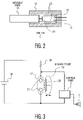
- FIG. 3 is a view showing an example of a circuit construction for detecting conduction of the switch in the information apparatus according to the first embodiment of the invention.
- FIG. 4 is a view showing a construction when a cover part of the information apparatus according to the first embodiment of the invention is opened.
- FIG. 5 is a view showing a construction when a housing of the information apparatus according to the first embodiment of the invention is removed.
- FIG. 6 is a view showing another example of the switch of the information apparatus according to the first embodiment of the invention.
- FIG. 7 is an exploded perspective view showing a construction when an abnormality detector according to a second embodiment of the invention is viewed from a surface.
- FIG. 8 is an exploded perspective view showing a construction when the abnormality detector according to the second embodiment of the invention is viewed from back.
- FIG. 9 is a view showing a construction under the state where a second light shading part is fitted to a base part in the second embodiment of the invention.
- FIG. 10 is a view showing a part of a construction of an information apparatus according to a third embodiment of the invention.
- FIG. 11 is a block diagram showing the construction of the information apparatus according to the third embodiment of the invention.
- FIG. 1 is a view showing a construction of the information apparatus according to the first embodiment of the invention when it is used ordinarily.
- Housing 4 of information apparatus 1 according to the first embodiment of the invention is fixed to a predetermined surface (hereinafter explained as wall surface 11 ) of a support substrate such as a wall by use of known fitting means such as screws (not shown in the drawings).
- Cover part 6 is fitted in such a fashion as to cover a hole formed on the left side of housing 4 in FIG. 1 and the inside of housing 4 cannot be seen from outside of information apparatus 1 .
- Cover part 6 is fitted to housing 4 by use of well known fitting means such as a screw or a lock (not shown in the drawing).
- Switch 2 including pole-like movable part 13 and cylindrical fixed part 12 into which movable part 13 is pushed is provided as an abnormal detector inside housing 4 .
- FIG. 2 is a view showing an example of switch 2 of information apparatus 1 according to the first embodiment of the invention.
- switch 2 includes pole-like movable part 13 and cylindrical fixed part 12 into which movable part 13 is pushed. Movable part 13 is allowed to move on a substantially concentric axis relative to fixed part 12 .
- Movable part side contact 20 is disposed on movable part 13 on the right side in FIG. 2 and a pair of fixed part side contacts 21 is disposed on a surface opposing the surface on which the movable part side contact 20 is disposed.
- movable part 13 When no external force is imparted, movable part 13 is held by resilient force of known resilient means 25 such as a spring under the state where it is moved to the left in FIG. 2 and electric conduction is not established between fixed part side contacts 21 .
- resilient force of known resilient means 25 such as a spring under the state where it is moved to the left in FIG. 2 and electric conduction is not established between fixed part side contacts 21 .
- movable part 13 is pushed into fixed part 12 by any external force (when it moves to the right in FIG. 2 ), on the other hand, movable part side contact 20 and fixed part side contact 21 come into mutual contact and electric conduction is established between fixed part side contacts 21 .
- movable part 13 moves on substantially the same axis with respect to fixed part 12 , contact can be reliably established between movable part side contact 20 and fixed part side contact 21 .
- protuberance part 8 is disposed inside cover part 6 .
- Protuberance part 8 is held through opening of housing 4 opened on the left side of the sheet of the drawing in FIG. 1 under a state where movable part 13 of switch 2 is biased to the right in FIG. 1 and is pushed into fixed part 12 , that is, under a state where movable part side contact 20 and fixed part side contact 21 keep mutual contact.
- fixed part 12 of switch 2 since fixed part 12 of switch 2 is fitted to holder part 10 by a known method such as a method using an adhesive, fixed part 12 operates integrally with holder part 10 .
- Guide part 9 keeps holder part 10 in such a fashion that holder part 10 can move in a predetermined direction (in the horizontal direction in FIG. 1 ).
- fixed part 12 and holder part 10 are movable with respect to housing and when movable part 13 is a first movable part, they constitute a second movable part.
- a left-hand part (one of ends) of holder part 10 in FIG. 1 is elastically held by coil spring 7 .
- Protuberance part 14 is defined on the right-hand part (the other end side) of holder part 10 in FIG. 1 .
- the other end side of protuberance part 14 is biased to wall surface 11 through the opening defined in housing 4 and is held under the state where it is moved to the left in FIG. 1 .
- each of holder part 10 and fixed part 12 is elastically held at one of the ends by coil spring 7 and is held at the other end by wall surface 11 under the state where it is biased to the left in FIG. 1 .
- protuberance part 8 is controlled in such a fashion that movable part 13 of switch 2 can be pushed into fixed part 12 to thereby establish conduction between the terminals of switch 2 under the state where cover part 6 is fitted to housing 4 and protuberance part 14 is biased by wall surface 11 to the left in FIG. 1 .
- switch 2 when information apparatus 1 according to the first embodiment is ordinarily used, switch 2 is under the conduction state but when conduction of switch 2 is cut off, control part 3 connected to switch 2 detects this cut-off of conduction of switch 2 and causes alarm generation part 5 to raise an alarm.
- holder part 10 is resiliently held at one of its ends (left-hand portion in the sheet of the drawing in FIG. 4 ) by coil spring 7 and protuberance part 8 can reliably come off from holder part 10 and can be spaced apart from movable part 13 .
- information apparatus 1 can reliably raise an alarm when cover part 6 is opened.
- switch 2 has been explained about the case where conduction is established when pole-like movable part 13 as shown in FIG. 2 is pushed into fixed part 12 .
- the switch in the information apparatus according to the first embodiment of the invention is not limited to such a construction but can be applied to all switches having a movable part and a fixed part.
- FIG. 6 shows another construction of the switch of the information apparatus in the embodiment of the invention. Like reference numerals are used to identify like constituent elements having like constructions as in switch 2 shown in FIG. 2 and the explanation of such constituent elements will be omitted to simplify the explanation.
- Switch 42 shown in FIG. 6( a ) has a construction where sheet-like movable part 23 is pushed to fixed part 22 to establish conduction.
- Fixed part side contacts 21 are disposed on a surface of fixed part 22 opposing movable part 23 and movable part side contact 20 is provided to a surface of movable part 23 opposing fixed part 22 .
- resilient means 25 urges movable part 33 to the left in FIG. 6( b ) and movable part side contact 20 and fixed part side contact 21 are spaced apart from each other. Therefore, conduction is not established between fixed part side contacts 21 .
- movable part side contact 20 and fixed part side contact 21 come into mutual contact and conduction is established between fixed part side contacts 21 .
- control part 3 when a storage part (not shown) storing information is connected to control part 3 and control part 3 detects cut-off of conduction of switch 2 , control part 3 causes alarm generation part to raise an alarm and erases information stored in the storage part. It is thus possible to constitute an information apparatus that can prevent leak of information and has high security.
- an authentication apparatus which stores authentication information including password information and biometrix information such as a fingerprint pattern, an iris pattern or a face pattern stored in a storage part, an authentication apparatus having high security can be constituted.
- abnormality detector 101 includes pole-like first and second light shading parts 105 and 106 that are so disposed as to slide in auniaxial direction (X-axis direction in FIG. 7 and direction opposite to the former) on slide surface 119 of base part 110 .
- First light shading part 105 has holder part 127 formed at one of the ends thereof and pushed portion 118 to be pushed by an external structure (support substrate such as later-appearing cover part or wall) at the other end.
- Second light shading part 106 too, has holder part 126 formed at one of the ends thereof and pushed portion 117 at the other end. As shown in FIG. 7 and later-appearing FIG.
- Each of coil springs 123 and 124 is fitted to one of the ends of each of holder parts 127 and 126 of first and second light shading parts 105 and 106 . Resilient force of this coil spring 123 urges first light shading part 105 in the first direction, that is, a direction opposite to the X direction in FIG. 7 and resilient force of coil spring 124 urges second light shading part 106 in the second direction, that is, the X direction in FIG. 7 .
- second light shading part 106 and second light reception/emission part 122 are spaced apart through slide surface 119 , it is possible to reduce the possibility that dust, etc, occurring when second light shading part 106 slides on slide surface 119 mixes between light emission part 141 and light reception part 142 of second light reception/emission part 122 and invites an erroneous operation.
- protuberance portion 131 extending in the axial direction is formed in a surface that comes into contact with slide surface 119 of second light shading part 106 in order to reduce friction at the time of sliding.
- the surface of the top of protuberance part 131 having a smaller area comes into contact and slides than when the entire surface of slide surface of second shading part 106 comes into contact and slides. Therefore, friction between slide surface 119 and second light shading part 106 can be reduced.
- abnormality detector 101 of the invention includes first and second light reception/emission parts 121 and 122 each having a pair of light reception part 142 and a light emission part 141 on a substrate 120 , circuit part 132 connected to first and second light reception/emission parts 121 and 122 and outputting an abnormality signal when the output of at least one of first and second light reception/emission parts 121 and 122 is turned OFF, and a cable part 107 for sending the output from circuit part 132 to the outside.
- Connector part 108 is disposed at the distal end of cable part 107 to connect abnormal detector 101 to external apparatuses.
- Substrate 120 is fixed to base part 110 through screw 125 .
- Base part 110 is fixed inside an external apparatus as boss parts 116 and 136 formed at its ends are fixed by screws in housing of the external apparatus.
- second light shading part 106 is pushed part 117 of second light shading part 106 is urged by the door, the cover or the wall surface to the left in the sheet of FIG. 9 (direction opposite to X direction) as will be explained later and second light shading part 106 and protuberance part 128 move in the direction opposite to the X direction in FIG. 9 . Since second light shading part 106 is positioned outside the position between light emission part 141 and light reception part 142 of second light reception/emission part 122 , the rays of light from light emission part 141 of second light reception/emission part 122 are received by light reception part 142 and the output from second light reception/emission part 122 is turned ON.
- Second light shading part 106 moves to the right in FIG. 9 and protuberance part 128 moves to a position at which it cuts off light between light emission part 141 and light reception part 142 of second light reception/emission part 122 . Consequently, the output from second light reception/emission part 122 is turned OFF.
- first light shading part 105 and first light reception/emission part 121 are the same as the relation between second light shading part 106 and second light reception/emission part 122 . Since first light shading part 105 is constituted in the opposite direction to second light shading part 106 , however, it is urged to the right (X direction) in the sheet of drawing in FIG. 9 and when tampering is detected, it is urged to the left (direction opposite to X direction) in the sheet of drawing by resilient force of coil spring 123 , so that first light shading part 105 and protuberance part 129 move to the left in the sheet of drawing (opposite to X direction). This point is different.
- abnormality detector 101 outputs the abnormality signal during normal use when the outputs from first and second light emission/reception parts 121 and 122 are ON and when the output of at least one of first and second light reception/emission parts 121 and 122 changes to OFF. Therefore, when at least one of first and second light reception/emission parts 121 and 122 gets into trouble during normal use, its output changes from ON to OFF with the result that the abnormality signal is generated and the trouble can be detected.
- the second embodiment of the invention represents the example where first and second light shading parts 105 and 106 are arranged in parallel with each other and are movable in the mutually opposite directions but the abnormality detector and the information apparatus using the abnormality detector according to the invention are not limited thereto.
- first and second light shading parts 105 and 106 are disposed at arbitrary angles and are movable in mutually different directions.
- FIG. 10 is a view showing a part of a construction of information apparatus 160 according to the third embodiment of the invention.
- Information apparatus 160 shown in FIG. 10 represents the construction during normal use when tampering is not detected.
- Abnormality detector 101 is held inside information apparatus 160 since pushed portion 118 of first light shading part 105 is urged to the right in FIG. 10 by cover part 151 of information apparatus 160 .
- a hole is formed in housing 164 of information apparatus 160 and pushed part 117 of second light shading part 106 is urged to the left in FIG. 10 by wall surface 152 .
- the outputs from both first and second light reception/emission parts 121 and 122 are kept ON as explained in the second embodiment.
- Information apparatus 160 to which abnormality detector 101 of the second embodiment of the invention is to be mounted can be applied broadly to various information apparatuses such as an authentication apparatus storing authentication information including a password, an iris pattern, a finger pattern and a face pattern, an entry/exist management apparatus, and so forth, so long as the apparatuses store information to be protected from tampering.
- an authentication apparatus storing authentication information including a password, an iris pattern, a finger pattern and a face pattern
- an entry/exist management apparatus and so forth, so long as the apparatuses store information to be protected from tampering.
- FIG. 11 is a block diagram showing a construction of information apparatus 160 according to the third embodiment of the invention.
- Power for driving is supplied from outside housing 164 to control part 162 and power supply part 165 through power supply port 166 .
- the kind of storage part 161 is not at all limited so long as storage part 161 can store and erase information. Therefore, it is possible to use various kinds of known devices such as a known RAM (random access memory), a known flash memory and a known HDD (hard disk drive).
- a known RAM random access memory
- a known flash memory random access memory
- HDD hard disk drive
- storage part 161 When a device requiring power for driving is used as storage part 161 , it is preferred to use a construction in which necessary power is supplied from power supply part 165 or from an external power source.
- alarm generation part 168 is preferably of a type that generates an alarm by sound because it attracts surrounding attention but may be of a type that raises an alarm by use of light or vibration.
- a known primary or secondary cell can be used as power supply part 165 . It is also possible to use a construction in which a chargeable secondary cell is used as power supply part 165 and power supply part 165 , too, is normally supplied with power from outside and is charged as shown in FIG. 11 .
- control part 162 detects the stop of supply of power from outside, power is supplied from power supply part 165 .
- the construction may be of a type such that control part 162 causes alarm generation part 168 to raise the alarm.
- the abnormality detector and the information apparatus using the abnormality detector according to the invention have the effect that they can detect tampering when the housing itself of the information apparatus is removed or carried away from the wall surface in addition to the case where the cover of the information apparatus having the abnormality detector mounted thereto is removed. Therefore, they are useful as the abnormality detector for detecting abnormality such as theft and as the information apparatus using the abnormality detector that store information to be protected from theft and leak of personal information and authentication information.
Landscapes
- Engineering & Computer Science (AREA)
- Physics & Mathematics (AREA)
- General Physics & Mathematics (AREA)
- Computer Hardware Design (AREA)
- Computer Security & Cryptography (AREA)
- Theoretical Computer Science (AREA)
- Software Systems (AREA)
- General Engineering & Computer Science (AREA)
- Burglar Alarm Systems (AREA)
- Force Measurement Appropriate To Specific Purposes (AREA)
Applications Claiming Priority (5)
| Application Number | Priority Date | Filing Date | Title |
|---|---|---|---|
| JP2003-021847 | 2003-01-30 | ||
| JP2003021847A JP3770236B2 (ja) | 2003-01-30 | 2003-01-30 | 異常検知装置およびそれを用いた情報装置 |
| JP2003041127A JP3815442B2 (ja) | 2003-02-19 | 2003-02-19 | 情報装置 |
| JP2003-041127 | 2003-02-19 | ||
| PCT/JP2004/000697 WO2004068431A1 (ja) | 2003-01-30 | 2004-01-27 | 異常検知装置およびそれを用いた情報装置 |
Publications (2)
| Publication Number | Publication Date |
|---|---|
| US20050179555A1 US20050179555A1 (en) | 2005-08-18 |
| US7167092B2 true US7167092B2 (en) | 2007-01-23 |
Family
ID=32828910
Family Applications (1)
| Application Number | Title | Priority Date | Filing Date |
|---|---|---|---|
| US10/515,755 Expired - Fee Related US7167092B2 (en) | 2003-01-30 | 2004-01-27 | Abnormality detector and information apparatus using the same |
Country Status (4)
| Country | Link |
|---|---|
| US (1) | US7167092B2 (de) |
| EP (1) | EP1494188B1 (de) |
| DE (1) | DE602004016599D1 (de) |
| WO (1) | WO2004068431A1 (de) |
Cited By (5)
| Publication number | Priority date | Publication date | Assignee | Title |
|---|---|---|---|---|
| US20070040674A1 (en) * | 2005-08-16 | 2007-02-22 | Honeywell International, Inc. | Conductive tamper switch for security devices |
| US20070290845A1 (en) * | 2006-06-14 | 2007-12-20 | Faycal Benjelloun | Tamper detection mechanism for blind installation of circular sensors |
| US20110199225A1 (en) * | 2010-02-15 | 2011-08-18 | Honeywell International Inc. | Use of token switch to indicate unauthorized manipulation of a protected device |
| WO2018004640A1 (en) * | 2016-07-01 | 2018-01-04 | Landis+Gyr Innovations, Inc. | Utility meter enclosure with tamper detection switch |
| US10489614B2 (en) | 2017-09-26 | 2019-11-26 | Hewlett Packard Enterprise Development Lp | Tamper detecting cases |
Families Citing this family (11)
| Publication number | Priority date | Publication date | Assignee | Title |
|---|---|---|---|---|
| US7292145B2 (en) | 2005-02-24 | 2007-11-06 | Robert Bosch Gmbh | Tamper switch arrangement |
| WO2007121508A1 (en) * | 2006-04-21 | 2007-11-01 | Richard Ruggiero | Spring-loaded, circuit-breaking, security seal |
| TWI354890B (en) * | 2007-01-18 | 2011-12-21 | Askey Computer Corp | Portable electronic device with a function of dete |
| US7602286B2 (en) * | 2007-07-09 | 2009-10-13 | Robert Bosch Gmbh | Tamper detector for a security sensor |
| ITMI20082108A1 (it) * | 2008-11-26 | 2010-05-26 | Securtech S N C Di Marino Sacchi & C | Allarme per pannelli fotovoltaici dotato di sistema per l'interruzione dell'energia prodotta |
| TWI402776B (zh) * | 2010-06-25 | 2013-07-21 | 纜線防盜系統與方法 | |
| GB201017104D0 (en) * | 2010-10-11 | 2010-11-24 | Cooper Security Ltd | Alarm apparatus |
| JP2016115080A (ja) * | 2014-12-12 | 2016-06-23 | 株式会社オートネットワーク技術研究所 | 情報処理装置 |
| PT3499479T (pt) * | 2017-12-13 | 2021-06-18 | Verisure Sarl | Um periférico de alarme com disposição antiarrombamento e uma disposição antiarrombamento |
| CN208766800U (zh) * | 2018-10-11 | 2019-04-19 | 中磊电子(苏州)有限公司 | 可检测并回报擅动的电子装置 |
| CN111079207B (zh) * | 2020-03-13 | 2020-11-24 | 新沂市锡沂高新材料产业技术研究院有限公司 | 一种防盗窃指纹开机计算机主机保护箱 |
Citations (16)
| Publication number | Priority date | Publication date | Assignee | Title |
|---|---|---|---|---|
| JPS4898084A (de) | 1972-03-30 | 1973-12-13 | ||
| FR2298144A1 (fr) | 1975-01-15 | 1976-08-13 | Agostini Sa | Detecteur d'effraction |
| US4236148A (en) * | 1979-03-19 | 1980-11-25 | Crown Auto Top Manufacturing Co. | Theft deterring and signalling device for portable fire extinguishers |
| US4418336A (en) * | 1981-07-17 | 1983-11-29 | Taylor John D | Alarm indicating dislocation of fire extinguisher |
| US4631526A (en) * | 1982-06-10 | 1986-12-23 | Automated Security Holdings, Ltd. | Theft proof alarm bell assembly |
| JPH05325751A (ja) | 1992-05-21 | 1993-12-10 | Matsushita Electric Works Ltd | 異常信号発生機器 |
| EP0786751A2 (de) | 1996-01-29 | 1997-07-30 | GRUNDIG Aktiengesellschaft | Vorrichtung zur Befestigung von Komponenten von Alarmanlagen |
| JPH09212754A (ja) | 1996-01-31 | 1997-08-15 | Matsushita Electric Works Ltd | 発信器 |
| JPH10116393A (ja) | 1996-10-15 | 1998-05-06 | Kubota Corp | 盗難防止用検出具の取付治具 |
| JP2781127B2 (ja) | 1993-06-11 | 1998-07-30 | 三菱電機株式会社 | 電子機器筐体 |
| JPH11283134A (ja) | 1998-03-31 | 1999-10-15 | Kubota Corp | 盗難防止タグ |
| EP0955616A1 (de) | 1998-05-07 | 1999-11-10 | Hi-G-Tek Ltd | Elektronisches etikett |
| JP2000261698A (ja) | 1999-03-05 | 2000-09-22 | Matsushita Electric Ind Co Ltd | 虹彩カメラ |
| EP1174839A2 (de) | 2000-07-19 | 2002-01-23 | Vimar SpA | Einmischungsschutzvorrichtung und bezogenes Verfahren zur Detektion von Einmischung innerhalb eines Gerätes |
| JP2002054365A (ja) | 2000-08-10 | 2002-02-20 | Yamatake Building Systems Co Ltd | 扉付き装置 |
| JP2003308523A (ja) | 2002-04-15 | 2003-10-31 | Oki Electric Ind Co Ltd | 虹彩撮影装置 |
Family Cites Families (1)
| Publication number | Priority date | Publication date | Assignee | Title |
|---|---|---|---|---|
| JPS4898084U (de) * | 1972-02-25 | 1973-11-20 |
-
2004
- 2004-01-27 DE DE602004016599T patent/DE602004016599D1/de not_active Expired - Fee Related
- 2004-01-27 WO PCT/JP2004/000697 patent/WO2004068431A1/ja active IP Right Grant
- 2004-01-27 EP EP04705494A patent/EP1494188B1/de not_active Expired - Fee Related
- 2004-01-27 US US10/515,755 patent/US7167092B2/en not_active Expired - Fee Related
Patent Citations (16)
| Publication number | Priority date | Publication date | Assignee | Title |
|---|---|---|---|---|
| JPS4898084A (de) | 1972-03-30 | 1973-12-13 | ||
| FR2298144A1 (fr) | 1975-01-15 | 1976-08-13 | Agostini Sa | Detecteur d'effraction |
| US4236148A (en) * | 1979-03-19 | 1980-11-25 | Crown Auto Top Manufacturing Co. | Theft deterring and signalling device for portable fire extinguishers |
| US4418336A (en) * | 1981-07-17 | 1983-11-29 | Taylor John D | Alarm indicating dislocation of fire extinguisher |
| US4631526A (en) * | 1982-06-10 | 1986-12-23 | Automated Security Holdings, Ltd. | Theft proof alarm bell assembly |
| JPH05325751A (ja) | 1992-05-21 | 1993-12-10 | Matsushita Electric Works Ltd | 異常信号発生機器 |
| JP2781127B2 (ja) | 1993-06-11 | 1998-07-30 | 三菱電機株式会社 | 電子機器筐体 |
| EP0786751A2 (de) | 1996-01-29 | 1997-07-30 | GRUNDIG Aktiengesellschaft | Vorrichtung zur Befestigung von Komponenten von Alarmanlagen |
| JPH09212754A (ja) | 1996-01-31 | 1997-08-15 | Matsushita Electric Works Ltd | 発信器 |
| JPH10116393A (ja) | 1996-10-15 | 1998-05-06 | Kubota Corp | 盗難防止用検出具の取付治具 |
| JPH11283134A (ja) | 1998-03-31 | 1999-10-15 | Kubota Corp | 盗難防止タグ |
| EP0955616A1 (de) | 1998-05-07 | 1999-11-10 | Hi-G-Tek Ltd | Elektronisches etikett |
| JP2000261698A (ja) | 1999-03-05 | 2000-09-22 | Matsushita Electric Ind Co Ltd | 虹彩カメラ |
| EP1174839A2 (de) | 2000-07-19 | 2002-01-23 | Vimar SpA | Einmischungsschutzvorrichtung und bezogenes Verfahren zur Detektion von Einmischung innerhalb eines Gerätes |
| JP2002054365A (ja) | 2000-08-10 | 2002-02-20 | Yamatake Building Systems Co Ltd | 扉付き装置 |
| JP2003308523A (ja) | 2002-04-15 | 2003-10-31 | Oki Electric Ind Co Ltd | 虹彩撮影装置 |
Non-Patent Citations (2)
| Title |
|---|
| European Search Report corresponding to application No. EP 04-70-5494 dated May 13, 2005. |
| International Search Report corresponding to application No. PCT/JP2004/000697 dated Apr. 20, 2004. |
Cited By (7)
| Publication number | Priority date | Publication date | Assignee | Title |
|---|---|---|---|---|
| US20070040674A1 (en) * | 2005-08-16 | 2007-02-22 | Honeywell International, Inc. | Conductive tamper switch for security devices |
| US7388484B2 (en) * | 2005-08-16 | 2008-06-17 | Honeywell International Inc. | Conductive tamper switch for security devices |
| US20070290845A1 (en) * | 2006-06-14 | 2007-12-20 | Faycal Benjelloun | Tamper detection mechanism for blind installation of circular sensors |
| US7528717B2 (en) * | 2006-06-14 | 2009-05-05 | Honeywell International Inc. | Tamper detection mechanism for blind installation of circular sensors |
| US20110199225A1 (en) * | 2010-02-15 | 2011-08-18 | Honeywell International Inc. | Use of token switch to indicate unauthorized manipulation of a protected device |
| WO2018004640A1 (en) * | 2016-07-01 | 2018-01-04 | Landis+Gyr Innovations, Inc. | Utility meter enclosure with tamper detection switch |
| US10489614B2 (en) | 2017-09-26 | 2019-11-26 | Hewlett Packard Enterprise Development Lp | Tamper detecting cases |
Also Published As
| Publication number | Publication date |
|---|---|
| EP1494188A1 (de) | 2005-01-05 |
| WO2004068431A1 (ja) | 2004-08-12 |
| EP1494188A4 (de) | 2005-06-29 |
| DE602004016599D1 (de) | 2008-10-30 |
| US20050179555A1 (en) | 2005-08-18 |
| EP1494188B1 (de) | 2008-09-17 |
Similar Documents
| Publication | Publication Date | Title |
|---|---|---|
| US7167092B2 (en) | Abnormality detector and information apparatus using the same | |
| US8006101B2 (en) | Radio transceiver or other encryption device having secure tamper-detection module | |
| US8615612B1 (en) | Avionics data storage device and transfer system with electro-opto-mechanical identification | |
| US20090181290A1 (en) | System and Method for an Automated Battery Arrangement | |
| CN103136479B (zh) | 移动终端的信息保护方法及装置 | |
| US7820313B2 (en) | Fuel source recognition and gating apparatus and associated method | |
| US7049970B2 (en) | Tamper sensing method and apparatus | |
| EP1647942B1 (de) | Biometrisches Sicherheitssystem | |
| KR20080099223A (ko) | 비휘발성 저장 장치와 방법 | |
| KR102023852B1 (ko) | 공공 사용 공간의 룸에 적용되는 스마트 도어락 | |
| JP3770236B2 (ja) | 異常検知装置およびそれを用いた情報装置 | |
| JP2006527953A (ja) | モバイル電子装置用の盗難防止システム | |
| KR102187774B1 (ko) | 실내 인입 통신케이블 보호장치 | |
| KR20050102771A (ko) | 전자석을 이용한 하이브리드형 잠금 장치 | |
| JP3815442B2 (ja) | 情報装置 | |
| CN108492418A (zh) | 一种网络端口安全电子锁及其专用拔出工具 | |
| US7709756B2 (en) | Safety switch | |
| KR102073493B1 (ko) | 사용 신뢰성을 높인 공공 사용 공간의 룸용 스마트 도어락 | |
| KR102073494B1 (ko) | 사용 신뢰성을 높인 공공 사용 공간의 룸용 스마트 도어락을 가지는 방범 룸도어 | |
| KR20180010617A (ko) | 휴대용 전자자물쇠 | |
| JP2008159479A (ja) | コンセント | |
| JP2007175373A (ja) | 電子機器の蓋開閉検出方法および蓋固定機構 | |
| CN101820165A (zh) | 报警系统用的电源装置 | |
| JP2018120462A (ja) | セキュリティ機器の着脱状態判別スイッチ | |
| KR102630652B1 (ko) | 서지 체크 장치 |
Legal Events
| Date | Code | Title | Description |
|---|---|---|---|
| FEPP | Fee payment procedure |
Free format text: PAYOR NUMBER ASSIGNED (ORIGINAL EVENT CODE: ASPN); ENTITY STATUS OF PATENT OWNER: LARGE ENTITY |
|
| REMI | Maintenance fee reminder mailed | ||
| LAPS | Lapse for failure to pay maintenance fees | ||
| STCH | Information on status: patent discontinuation |
Free format text: PATENT EXPIRED DUE TO NONPAYMENT OF MAINTENANCE FEES UNDER 37 CFR 1.362 |
|
| FP | Lapsed due to failure to pay maintenance fee |
Effective date: 20110123 |