US7165470B2 - Vehicular drive system and driving method - Google Patents
Vehicular drive system and driving method Download PDFInfo
- Publication number
- US7165470B2 US7165470B2 US11/002,140 US214004A US7165470B2 US 7165470 B2 US7165470 B2 US 7165470B2 US 214004 A US214004 A US 214004A US 7165470 B2 US7165470 B2 US 7165470B2
- Authority
- US
- United States
- Prior art keywords
- power unit
- shift
- gear
- input
- intermediate shaft
- Prior art date
- Legal status (The legal status is an assumption and is not a legal conclusion. Google has not performed a legal analysis and makes no representation as to the accuracy of the status listed.)
- Expired - Lifetime, expires
Links
Images




Classifications
-
- B—PERFORMING OPERATIONS; TRANSPORTING
- B60—VEHICLES IN GENERAL
- B60K—ARRANGEMENT OR MOUNTING OF PROPULSION UNITS OR OF TRANSMISSIONS IN VEHICLES; ARRANGEMENT OR MOUNTING OF PLURAL DIVERSE PRIME-MOVERS IN VEHICLES; AUXILIARY DRIVES FOR VEHICLES; INSTRUMENTATION OR DASHBOARDS FOR VEHICLES; ARRANGEMENTS IN CONNECTION WITH COOLING, AIR INTAKE, GAS EXHAUST OR FUEL SUPPLY OF PROPULSION UNITS IN VEHICLES
- B60K6/00—Arrangement or mounting of plural diverse prime-movers for mutual or common propulsion, e.g. hybrid propulsion systems comprising electric motors and internal combustion engines
- B60K6/20—Arrangement or mounting of plural diverse prime-movers for mutual or common propulsion, e.g. hybrid propulsion systems comprising electric motors and internal combustion engines the prime-movers consisting of electric motors and internal combustion engines, e.g. HEVs
- B60K6/22—Arrangement or mounting of plural diverse prime-movers for mutual or common propulsion, e.g. hybrid propulsion systems comprising electric motors and internal combustion engines the prime-movers consisting of electric motors and internal combustion engines, e.g. HEVs characterised by apparatus, components or means specially adapted for HEVs
- B60K6/36—Arrangement or mounting of plural diverse prime-movers for mutual or common propulsion, e.g. hybrid propulsion systems comprising electric motors and internal combustion engines the prime-movers consisting of electric motors and internal combustion engines, e.g. HEVs characterised by apparatus, components or means specially adapted for HEVs characterised by the transmission gearings
- B60K6/365—Arrangement or mounting of plural diverse prime-movers for mutual or common propulsion, e.g. hybrid propulsion systems comprising electric motors and internal combustion engines the prime-movers consisting of electric motors and internal combustion engines, e.g. HEVs characterised by apparatus, components or means specially adapted for HEVs characterised by the transmission gearings with the gears having orbital motion
-
- B—PERFORMING OPERATIONS; TRANSPORTING
- B60—VEHICLES IN GENERAL
- B60W—CONJOINT CONTROL OF VEHICLE SUB-UNITS OF DIFFERENT TYPE OR DIFFERENT FUNCTION; CONTROL SYSTEMS SPECIALLY ADAPTED FOR HYBRID VEHICLES; ROAD VEHICLE DRIVE CONTROL SYSTEMS FOR PURPOSES NOT RELATED TO THE CONTROL OF A PARTICULAR SUB-UNIT
- B60W20/00—Control systems specially adapted for hybrid vehicles
- B60W20/40—Controlling the engagement or disengagement of prime movers, e.g. for transition between prime movers
-
- B—PERFORMING OPERATIONS; TRANSPORTING
- B60—VEHICLES IN GENERAL
- B60K—ARRANGEMENT OR MOUNTING OF PROPULSION UNITS OR OF TRANSMISSIONS IN VEHICLES; ARRANGEMENT OR MOUNTING OF PLURAL DIVERSE PRIME-MOVERS IN VEHICLES; AUXILIARY DRIVES FOR VEHICLES; INSTRUMENTATION OR DASHBOARDS FOR VEHICLES; ARRANGEMENTS IN CONNECTION WITH COOLING, AIR INTAKE, GAS EXHAUST OR FUEL SUPPLY OF PROPULSION UNITS IN VEHICLES
- B60K6/00—Arrangement or mounting of plural diverse prime-movers for mutual or common propulsion, e.g. hybrid propulsion systems comprising electric motors and internal combustion engines
- B60K6/20—Arrangement or mounting of plural diverse prime-movers for mutual or common propulsion, e.g. hybrid propulsion systems comprising electric motors and internal combustion engines the prime-movers consisting of electric motors and internal combustion engines, e.g. HEVs
- B60K6/42—Arrangement or mounting of plural diverse prime-movers for mutual or common propulsion, e.g. hybrid propulsion systems comprising electric motors and internal combustion engines the prime-movers consisting of electric motors and internal combustion engines, e.g. HEVs characterised by the architecture of the hybrid electric vehicle
- B60K6/48—Parallel type
-
- B—PERFORMING OPERATIONS; TRANSPORTING
- B60—VEHICLES IN GENERAL
- B60W—CONJOINT CONTROL OF VEHICLE SUB-UNITS OF DIFFERENT TYPE OR DIFFERENT FUNCTION; CONTROL SYSTEMS SPECIALLY ADAPTED FOR HYBRID VEHICLES; ROAD VEHICLE DRIVE CONTROL SYSTEMS FOR PURPOSES NOT RELATED TO THE CONTROL OF A PARTICULAR SUB-UNIT
- B60W10/00—Conjoint control of vehicle sub-units of different type or different function
- B60W10/04—Conjoint control of vehicle sub-units of different type or different function including control of propulsion units
- B60W10/08—Conjoint control of vehicle sub-units of different type or different function including control of propulsion units including control of electric propulsion units, e.g. motors or generators
-
- B—PERFORMING OPERATIONS; TRANSPORTING
- B60—VEHICLES IN GENERAL
- B60W—CONJOINT CONTROL OF VEHICLE SUB-UNITS OF DIFFERENT TYPE OR DIFFERENT FUNCTION; CONTROL SYSTEMS SPECIALLY ADAPTED FOR HYBRID VEHICLES; ROAD VEHICLE DRIVE CONTROL SYSTEMS FOR PURPOSES NOT RELATED TO THE CONTROL OF A PARTICULAR SUB-UNIT
- B60W30/00—Purposes of road vehicle drive control systems not related to the control of a particular sub-unit, e.g. of systems using conjoint control of vehicle sub-units
- B60W30/18—Propelling the vehicle
- B60W30/19—Improvement of gear change, e.g. by synchronisation or smoothing gear shift
-
- F—MECHANICAL ENGINEERING; LIGHTING; HEATING; WEAPONS; BLASTING
- F16—ENGINEERING ELEMENTS AND UNITS; GENERAL MEASURES FOR PRODUCING AND MAINTAINING EFFECTIVE FUNCTIONING OF MACHINES OR INSTALLATIONS; THERMAL INSULATION IN GENERAL
- F16H—GEARING
- F16H3/00—Toothed gearings for conveying rotary motion with variable gear ratio or for reversing rotary motion
- F16H3/02—Toothed gearings for conveying rotary motion with variable gear ratio or for reversing rotary motion without gears having orbital motion
- F16H3/08—Toothed gearings for conveying rotary motion with variable gear ratio or for reversing rotary motion without gears having orbital motion exclusively or essentially with continuously meshing gears, that can be disengaged from their shafts
- F16H3/12—Toothed gearings for conveying rotary motion with variable gear ratio or for reversing rotary motion without gears having orbital motion exclusively or essentially with continuously meshing gears, that can be disengaged from their shafts with means for synchronisation not incorporated in the clutches
- F16H3/126—Toothed gearings for conveying rotary motion with variable gear ratio or for reversing rotary motion without gears having orbital motion exclusively or essentially with continuously meshing gears, that can be disengaged from their shafts with means for synchronisation not incorporated in the clutches using an electric drive
-
- F—MECHANICAL ENGINEERING; LIGHTING; HEATING; WEAPONS; BLASTING
- F16—ENGINEERING ELEMENTS AND UNITS; GENERAL MEASURES FOR PRODUCING AND MAINTAINING EFFECTIVE FUNCTIONING OF MACHINES OR INSTALLATIONS; THERMAL INSULATION IN GENERAL
- F16H—GEARING
- F16H61/00—Control functions within control units of change-speed- or reversing-gearings for conveying rotary motion ; Control of exclusively fluid gearing, friction gearing, gearings with endless flexible members or other particular types of gearing
- F16H61/04—Smoothing ratio shift
- F16H61/0403—Synchronisation before shifting
-
- B—PERFORMING OPERATIONS; TRANSPORTING
- B60—VEHICLES IN GENERAL
- B60W—CONJOINT CONTROL OF VEHICLE SUB-UNITS OF DIFFERENT TYPE OR DIFFERENT FUNCTION; CONTROL SYSTEMS SPECIALLY ADAPTED FOR HYBRID VEHICLES; ROAD VEHICLE DRIVE CONTROL SYSTEMS FOR PURPOSES NOT RELATED TO THE CONTROL OF A PARTICULAR SUB-UNIT
- B60W20/00—Control systems specially adapted for hybrid vehicles
-
- F—MECHANICAL ENGINEERING; LIGHTING; HEATING; WEAPONS; BLASTING
- F16—ENGINEERING ELEMENTS AND UNITS; GENERAL MEASURES FOR PRODUCING AND MAINTAINING EFFECTIVE FUNCTIONING OF MACHINES OR INSTALLATIONS; THERMAL INSULATION IN GENERAL
- F16H—GEARING
- F16H3/00—Toothed gearings for conveying rotary motion with variable gear ratio or for reversing rotary motion
- F16H3/02—Toothed gearings for conveying rotary motion with variable gear ratio or for reversing rotary motion without gears having orbital motion
- F16H3/08—Toothed gearings for conveying rotary motion with variable gear ratio or for reversing rotary motion without gears having orbital motion exclusively or essentially with continuously meshing gears, that can be disengaged from their shafts
- F16H2003/0818—Toothed gearings for conveying rotary motion with variable gear ratio or for reversing rotary motion without gears having orbital motion exclusively or essentially with continuously meshing gears, that can be disengaged from their shafts comprising means for power-shifting
-
- F—MECHANICAL ENGINEERING; LIGHTING; HEATING; WEAPONS; BLASTING
- F16—ENGINEERING ELEMENTS AND UNITS; GENERAL MEASURES FOR PRODUCING AND MAINTAINING EFFECTIVE FUNCTIONING OF MACHINES OR INSTALLATIONS; THERMAL INSULATION IN GENERAL
- F16H—GEARING
- F16H61/00—Control functions within control units of change-speed- or reversing-gearings for conveying rotary motion ; Control of exclusively fluid gearing, friction gearing, gearings with endless flexible members or other particular types of gearing
- F16H61/04—Smoothing ratio shift
- F16H61/0403—Synchronisation before shifting
- F16H2061/0422—Synchronisation before shifting by an electric machine, e.g. by accelerating or braking the input shaft
-
- F—MECHANICAL ENGINEERING; LIGHTING; HEATING; WEAPONS; BLASTING
- F16—ENGINEERING ELEMENTS AND UNITS; GENERAL MEASURES FOR PRODUCING AND MAINTAINING EFFECTIVE FUNCTIONING OF MACHINES OR INSTALLATIONS; THERMAL INSULATION IN GENERAL
- F16H—GEARING
- F16H61/00—Control functions within control units of change-speed- or reversing-gearings for conveying rotary motion ; Control of exclusively fluid gearing, friction gearing, gearings with endless flexible members or other particular types of gearing
- F16H61/04—Smoothing ratio shift
- F16H2061/0425—Bridging torque interruption
- F16H2061/0433—Bridging torque interruption by torque supply with an electric motor
-
- F—MECHANICAL ENGINEERING; LIGHTING; HEATING; WEAPONS; BLASTING
- F16—ENGINEERING ELEMENTS AND UNITS; GENERAL MEASURES FOR PRODUCING AND MAINTAINING EFFECTIVE FUNCTIONING OF MACHINES OR INSTALLATIONS; THERMAL INSULATION IN GENERAL
- F16H—GEARING
- F16H61/00—Control functions within control units of change-speed- or reversing-gearings for conveying rotary motion ; Control of exclusively fluid gearing, friction gearing, gearings with endless flexible members or other particular types of gearing
- F16H61/04—Smoothing ratio shift
- F16H2061/0492—Smoothing ratio shift for high engine torque, e.g. during acceleration or uphill driving
-
- F—MECHANICAL ENGINEERING; LIGHTING; HEATING; WEAPONS; BLASTING
- F16—ENGINEERING ELEMENTS AND UNITS; GENERAL MEASURES FOR PRODUCING AND MAINTAINING EFFECTIVE FUNCTIONING OF MACHINES OR INSTALLATIONS; THERMAL INSULATION IN GENERAL
- F16H—GEARING
- F16H61/00—Control functions within control units of change-speed- or reversing-gearings for conveying rotary motion ; Control of exclusively fluid gearing, friction gearing, gearings with endless flexible members or other particular types of gearing
- F16H61/04—Smoothing ratio shift
- F16H2061/0496—Smoothing ratio shift for low engine torque, e.g. during coasting, sailing or engine braking
-
- F—MECHANICAL ENGINEERING; LIGHTING; HEATING; WEAPONS; BLASTING
- F16—ENGINEERING ELEMENTS AND UNITS; GENERAL MEASURES FOR PRODUCING AND MAINTAINING EFFECTIVE FUNCTIONING OF MACHINES OR INSTALLATIONS; THERMAL INSULATION IN GENERAL
- F16H—GEARING
- F16H2200/00—Transmissions for multiple ratios
- F16H2200/003—Transmissions for multiple ratios characterised by the number of forward speeds
- F16H2200/0052—Transmissions for multiple ratios characterised by the number of forward speeds the gear ratios comprising six forward speeds
-
- F—MECHANICAL ENGINEERING; LIGHTING; HEATING; WEAPONS; BLASTING
- F16—ENGINEERING ELEMENTS AND UNITS; GENERAL MEASURES FOR PRODUCING AND MAINTAINING EFFECTIVE FUNCTIONING OF MACHINES OR INSTALLATIONS; THERMAL INSULATION IN GENERAL
- F16H—GEARING
- F16H2306/00—Shifting
- F16H2306/40—Shifting activities
- F16H2306/46—Uncoupling of current gear
-
- F—MECHANICAL ENGINEERING; LIGHTING; HEATING; WEAPONS; BLASTING
- F16—ENGINEERING ELEMENTS AND UNITS; GENERAL MEASURES FOR PRODUCING AND MAINTAINING EFFECTIVE FUNCTIONING OF MACHINES OR INSTALLATIONS; THERMAL INSULATION IN GENERAL
- F16H—GEARING
- F16H2306/00—Shifting
- F16H2306/40—Shifting activities
- F16H2306/50—Coupling of new gear
-
- F—MECHANICAL ENGINEERING; LIGHTING; HEATING; WEAPONS; BLASTING
- F16—ENGINEERING ELEMENTS AND UNITS; GENERAL MEASURES FOR PRODUCING AND MAINTAINING EFFECTIVE FUNCTIONING OF MACHINES OR INSTALLATIONS; THERMAL INSULATION IN GENERAL
- F16H—GEARING
- F16H3/00—Toothed gearings for conveying rotary motion with variable gear ratio or for reversing rotary motion
- F16H3/006—Toothed gearings for conveying rotary motion with variable gear ratio or for reversing rotary motion power being selectively transmitted by parallel flow paths, e.g. dual clutch transmissions
-
- F—MECHANICAL ENGINEERING; LIGHTING; HEATING; WEAPONS; BLASTING
- F16—ENGINEERING ELEMENTS AND UNITS; GENERAL MEASURES FOR PRODUCING AND MAINTAINING EFFECTIVE FUNCTIONING OF MACHINES OR INSTALLATIONS; THERMAL INSULATION IN GENERAL
- F16H—GEARING
- F16H3/00—Toothed gearings for conveying rotary motion with variable gear ratio or for reversing rotary motion
- F16H3/44—Toothed gearings for conveying rotary motion with variable gear ratio or for reversing rotary motion using gears having orbital motion
- F16H3/72—Toothed gearings for conveying rotary motion with variable gear ratio or for reversing rotary motion using gears having orbital motion with a secondary drive, e.g. regulating motor, in order to vary speed continuously
- F16H3/724—Toothed gearings for conveying rotary motion with variable gear ratio or for reversing rotary motion using gears having orbital motion with a secondary drive, e.g. regulating motor, in order to vary speed continuously using externally powered electric machines
- F16H3/725—Toothed gearings for conveying rotary motion with variable gear ratio or for reversing rotary motion using gears having orbital motion with a secondary drive, e.g. regulating motor, in order to vary speed continuously using externally powered electric machines with means to change ratio in the mechanical gearing
-
- F—MECHANICAL ENGINEERING; LIGHTING; HEATING; WEAPONS; BLASTING
- F16—ENGINEERING ELEMENTS AND UNITS; GENERAL MEASURES FOR PRODUCING AND MAINTAINING EFFECTIVE FUNCTIONING OF MACHINES OR INSTALLATIONS; THERMAL INSULATION IN GENERAL
- F16H—GEARING
- F16H61/00—Control functions within control units of change-speed- or reversing-gearings for conveying rotary motion ; Control of exclusively fluid gearing, friction gearing, gearings with endless flexible members or other particular types of gearing
- F16H61/68—Control functions within control units of change-speed- or reversing-gearings for conveying rotary motion ; Control of exclusively fluid gearing, friction gearing, gearings with endless flexible members or other particular types of gearing specially adapted for stepped gearings
- F16H61/682—Control functions within control units of change-speed- or reversing-gearings for conveying rotary motion ; Control of exclusively fluid gearing, friction gearing, gearings with endless flexible members or other particular types of gearing specially adapted for stepped gearings with interruption of drive
-
- F—MECHANICAL ENGINEERING; LIGHTING; HEATING; WEAPONS; BLASTING
- F16—ENGINEERING ELEMENTS AND UNITS; GENERAL MEASURES FOR PRODUCING AND MAINTAINING EFFECTIVE FUNCTIONING OF MACHINES OR INSTALLATIONS; THERMAL INSULATION IN GENERAL
- F16H—GEARING
- F16H61/00—Control functions within control units of change-speed- or reversing-gearings for conveying rotary motion ; Control of exclusively fluid gearing, friction gearing, gearings with endless flexible members or other particular types of gearing
- F16H61/70—Control functions within control units of change-speed- or reversing-gearings for conveying rotary motion ; Control of exclusively fluid gearing, friction gearing, gearings with endless flexible members or other particular types of gearing specially adapted for change-speed gearing in group arrangement, i.e. with separate change-speed gear trains arranged in series, e.g. range or overdrive-type gearing arrangements
-
- Y—GENERAL TAGGING OF NEW TECHNOLOGICAL DEVELOPMENTS; GENERAL TAGGING OF CROSS-SECTIONAL TECHNOLOGIES SPANNING OVER SEVERAL SECTIONS OF THE IPC; TECHNICAL SUBJECTS COVERED BY FORMER USPC CROSS-REFERENCE ART COLLECTIONS [XRACs] AND DIGESTS
- Y02—TECHNOLOGIES OR APPLICATIONS FOR MITIGATION OR ADAPTATION AGAINST CLIMATE CHANGE
- Y02T—CLIMATE CHANGE MITIGATION TECHNOLOGIES RELATED TO TRANSPORTATION
- Y02T10/00—Road transport of goods or passengers
- Y02T10/60—Other road transportation technologies with climate change mitigation effect
- Y02T10/62—Hybrid vehicles
-
- Y—GENERAL TAGGING OF NEW TECHNOLOGICAL DEVELOPMENTS; GENERAL TAGGING OF CROSS-SECTIONAL TECHNOLOGIES SPANNING OVER SEVERAL SECTIONS OF THE IPC; TECHNICAL SUBJECTS COVERED BY FORMER USPC CROSS-REFERENCE ART COLLECTIONS [XRACs] AND DIGESTS
- Y10—TECHNICAL SUBJECTS COVERED BY FORMER USPC
- Y10T—TECHNICAL SUBJECTS COVERED BY FORMER US CLASSIFICATION
- Y10T74/00—Machine element or mechanism
- Y10T74/19—Gearing
- Y10T74/19219—Interchangeably locked
- Y10T74/19251—Control mechanism
-
- Y—GENERAL TAGGING OF NEW TECHNOLOGICAL DEVELOPMENTS; GENERAL TAGGING OF CROSS-SECTIONAL TECHNOLOGIES SPANNING OVER SEVERAL SECTIONS OF THE IPC; TECHNICAL SUBJECTS COVERED BY FORMER USPC CROSS-REFERENCE ART COLLECTIONS [XRACs] AND DIGESTS
- Y10—TECHNICAL SUBJECTS COVERED BY FORMER USPC
- Y10T—TECHNICAL SUBJECTS COVERED BY FORMER US CLASSIFICATION
- Y10T74/00—Machine element or mechanism
- Y10T74/19—Gearing
- Y10T74/19219—Interchangeably locked
- Y10T74/19284—Meshing assisters
Definitions
- the present invention relates to an automatic transmission, an automatic transmission control device, an automatic transmission control method, an automatic shift system, and a vehicle using the same.
- gear trains are arranged on two input shafts so as be different in gear ratio to decrease a change in rotation during a shift, whereby the output of a shifting power unit can be decreased.
- the number of gears used becomes twice as large, with a consequent likelihood of an increase of gear noise, mass, and weight.
- the vehicular drive system of the present invention is characterized in that a shifting power unit is not merely provided between an input shaft and an intermediate shaft, but a mechanism for transferring of power from the input shaft to both first and second intermediate shafts and for cutting off the power is provided; one side of the shifting power unit is connected to the input shaft, while an opposite side thereof is connected to a power transfer switching clutch; and the shifting power unit is connected to the first or the second intermediate shaft through a reduction mechanism.
- the output of the shifting power unit can be decreased while minimizing an increase in the number of gears.
- a gear ratio different from that of reduction gears in a transmission is provided in common, whereby the number of gears used can be decreased without increasing the capacity of a motor which is high in cost, and thus a more outstanding economical effect can be obtained.
- a vehicle driving power unit can be started without engaging a gear connected to an output shaft and hence there can be attained a highly quiet drivability without transfer of a starting shock to the vehicle.
- FIG. 1 is a construction diagram a vehicular drive system according to a first embodiment of the present invention
- FIG. 2 is a morphological diagram showing a mounted state of the vehicular drive system of FIG. 1 on an automobile;
- FIG. 3 is a construction diagram related to a control system shown in FIG. 1 ;
- FIG. 4 shows a torque transfer path at the time of start-up of an engine in FIG. 1 ;
- FIG. 5 is a flowchart of a control system in an up-shift
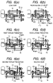
- FIG. 6 shows changing torque transfer paths and operations of claw clutches in an up-shift
- FIG. 7 is a time chart of torque and the number of revolutions in an up-shift
- FIG. 8 is a flowchart of the control system in a down-shift
- FIG. 9 shows changing torque transfer paths and operations of claw clutches in a down-shift
- FIG. 10 is a time chart of torque and the number of revolutions in a down-shift
- FIG. 11 shows changing torque transfer paths and operations of claw clutches in a jump shift
- FIG. 12 shows a second embodiment of the present invention.
- FIG. 13 shows a third embodiment of the present invention.
- FIG. 1 is a construction diagram showing a first embodiment of the present invention.
- a vehicle driving power unit 1 is coupled to an input shaft 300 of a transmission 2 .
- the vehicle driving power unit 1 is generally an internal combustion engine, but may be a power unit having a rotary shaft such as a motor.
- An output shaft 3 of the transmission 2 is connected to wheels (not shown).
- the input shaft 300 can transmit a driving force to a first intermediate shaft 13 and a second intermediate shaft 17 and cut off the supply of the driving force.
- the intermediate shaft 13 is selected, it is engaged to the input shaft through a direct-coupling gear 101
- the intermediate shaft 17 is selected, it is engaged to the input shaft through a direct-coupling gear 102 .
- shift gears 14 , 15 , 16 , 18 , 19 , and 20 the first and second intermediate shafts are connected to the output shaft 3 through dog clutches 21 , 22 , and 23 .
- the above dog clutches are connected to shift actuators 25 , 26 , 27 , 29 , and 30 , so that they can be engaged and disengaged with the driving force of the actuators.
- the actuators are usually automatic device such as a motor type or a hydraulic pressure type. Since the dog clutches and the actuators are of known techniques, detailed descriptions thereof will here be omitted.
- the input shaft 300 is connected to one shaft of a shifting power unit 200 .
- the other shaft of the shifting power unit 200 is connected to the first and second intermediate shafts 13 , 17 through a dog clutch 113 and further through motor gears 111 and 112 .
- This construction is a feature of the present invention.
- an electric motor is used as the shifting power unit 200 , it may be substituted by a friction clutch. That is, the shifting power unit 200 is not specially limited insofar as it has two shafts and can transfer or generate power.
- the shifting power unit 200 is constituted by an electric motor 5 and a planetary gear mechanism 31 .
- a rotary shaft of the motor is connected to a planetary gear in the planetary gear mechanism.
- the input shaft is connected to a sun gear and a ring gear is connected to a switching sleeve side of the dog clutch 113 .
- the power of the motor is provided to the input shaft and the first or second intermediate shaft.
- the power of the motor acts in opposite directions on the input shaft side and on the first or the second intermediate shaft side.
- the connection is set so as to increase the rotational speed of the input shaft when the motor generates a positive torque
- the torque provided to the intermediate shaft side acts to lower the rotational speed of the intermediate shaft.
- an electric motor used is of a construction permitting rotation of both stator and rotor, the motor alone may be installed as in an equivalent construction of FIG. 1 .
- FIG. 2 is a diagram showing a state in which the vehicular drive system of the present invention is mounted on an automobile.
- the transmission 2 is connected to the vehicle driving power unit 1 .
- the output shaft 3 drives wheels 4 through a differential gear.
- the motor 5 is installed within the transmission 2 .
- a motor controller 7 is connected electrically to the motor 5 and a battery 6 as a power supply of the motor controller 7 is mounted on the automobile.
- Many automobiles employ a lead storage battery, but in the system of the present invention the number of times of charge and discharge is large, thus causing deterioration of the battery. In the system, since charge and discharge are sure to occur during a shift, there is little change in the amount of stored electricity before and after the shift.
- An electronic controlled throttle valve 10 is provided in the vehicle driving power unit 1 , whereby the output of the vehicle driving power unit 1 can be controlled in accordance with a request signal.
- a shift controller 8 not only controls the torque and the number of revolutions of the motor 5 through the motor controller 7 but also controls the output of the vehicle driving power unit 1 through a vehicle driving power controller 9 and further through the electronic controlled throttle valve 10 . Further, the shift controller 8 commands the operation of the shift actuators 25 to 27 and 29 to 30 .
- FIG. 3 shows a control system in the case of using a motor as the shifting power unit 200 .
- the motor 5 is a permanent magnet synchronous motor and is supplied with three-phase alternating currents U, V, W by the motor controller 7 .
- High-speed switching elements 39 are provided respectively in three-phase arms of an inverter of the motor controller 7 to convert a direct-current voltage from the battery 6 to a three-phase alternating current of a variable frequency.
- an inverter controller 38 Upon receipt of a torque command and a number-of-revolutions command from the shift controller 8 , an inverter controller 38 not only controls a current passing rate of the inverter but also feeds back the output of current sensors 40 in each arm and the output of a rotor angle detecting position sensor 41 and makes control so that the torque and the number of revolutions of the motor 5 become respective commanded values.
- Such a control is publicly known in the field of power electronics and therefore a detailed explanation thereof will here be omitted.
- FIG. 4 shows engaged positions of dog clutches for starting an internal combustion engine (merely “engine” hereinafter) and a torque transfer path in the case of using the engine as the vehicle driving power unit 1 .
- the first intermediate shaft is fixed by engaging dog clutches 21 and 22 simultaneously, and when the dog clutch 113 is engaged with the first intermediate shaft, all the torque is applied to the engine 1 . Therefore, if torque is applied in the starting direction of the engine 1 , the engine begins rotating and becomes rotatable for itself.
- FIG. 5 is a flowchart of the control system in up-shift. With 1 ⁇ 2 power ON up-shift as an example, a gear switching state and a state of torque transition are shown. In FIG. 6 , changing torque transfer paths and operations of claw clutches (mesh type clutches) are shown in correspondence to steps in FIG. 5 .
- FIG. 7 is a time chart of torque and the number of revolutions in various portions.
- Step 1 a While the automobile is running with the low gear 14 engaged, the motor speed is controlled in Step 1 a , then in Step 1 b the motor speed is changed until the relation between the engine speed Ne and the number of revolutions Na of the second intermediate shaft is determined to be in a synchronized state.
- Step 1 c the dog clutch 113 is operated to engage the gear 112 .
- Step 2 a the motor speed is controlled, then in Step 2 B the motor speed is changed until determination of a synchronous state of the second gear 18 .
- G1.5 stands for the product of gear ratios of the second gear 18 and the motor gear 112
- G1 stands for a gear ratio of the low gear.
- Step 3 a If the motor torque is increased in a negative direction (a direction in which the torque serves as a driving force for the output shaft and as a load for the engine) in Step 3 a , an input torque of the second gear increases, while that of the low gear decreases. This is a torque transition process called torque phase.
- Step 3 b the shift controller 8 determines the end of torque phase, that is, determines that the input torque of the low gear 14 is zero.
- a value (Tm
- ) obtained when an actual motor torque has become equal to the absolute value of the engine torque can be regarded as the gear input torque being zero.
- the engine torque Te be determined beforehand by detection or by calculation. A concrete method for the detection or the calculation is disclosed in Japanese Patent Laid-Open Nos. H5(1993)-240073 and H6(1994)-317242 and therefore an explanation thereof will here be omitted.
- the direct-coupling gear 101 is also disengaged for direct coupling to the second gear.
- Step 4 a When the shift controller 8 issues a motor speed change command in Step 4 a , the engine speed changes toward an input number of revolutions of the second gear. This is a revolutions transition process called inertia phase.
- Step 4 b the shift controller 8 determines the end of inertia phase by detecting a synchronized state of the engine speed with the input number of revolutions of the subsequent gear.
- Step 4 c the shift controller 8 operates the dog clutch 103 to engage the direct-coupling gear 102 . Because of the synchronized state, the gear 102 can be engaged easily without causing any change in the operation of the transmission.
- Step 5 a the shift controller 8 issues a motor torque decreasing command, making the motor torque zero, whereupon the engine torque Te which has been transferred to G1.5 through the motor 5 shifts to the second gear.
- Step 5 b the shift controller 8 determines the end of the second torque phase by detecting that the motor torque Tm is zero.
- Step 5 c the shift controller 8 disengages the motor gear 112 and terminates the shift. Since Tm is zero, the motor gear can be disengaged easily without causing any change in the operation of the transmission.
- FIG. 8 is a flowchart of the control system in pedal depressing down-shift.
- FIG. 9 shows changing torque transfer paths and operations of claw clutches, for example in the case of 2 ⁇ 1 down-shift.
- FIG. 10 is a time chart of torque and the number of revolutions in various portions.
- Step 1 a While the automobile is running with the second gear engaged, the motor speed is controlled in Step 1 a and is changed in Step 1 b until a synchronized state of the motor gear 112 is determined.
- Step 2 a If the motor torque is increased in a negative direction (a direction in which the torque serves as a driving force for the output shaft and as a load for the engine) in Step 2 a , an input torque of the low gear increases, while that of the second gear decreases. This is a torque transition process called torque phase.
- Step 2 c the shift controller 8 makes the dog clutch 103 operate to disengage the direct-coupling gear 102 .
- Step 4 a When the shift controller 8 issues a motor speed change command in Step 4 a , the engine speed changes toward an input number of revolutions of the low gear. This is a revolutions transition process called inertia phase.
- Step 4 b the shift controller 8 determines the end of inertia phase by detecting a synchronized state of the engine speed with the input number of revolutions of the subsequent gear.
- Step 4 c the shift controller 8 operates the dog clutch 22 to engage the low gear 14 . Because of the synchronized state, the low gear 14 can be engaged easily without causing any change in the operation of the transmission.
- Step 5 a the shift controller 8 issues a motor torque decreasing command, making the motor torque zero, whereupon the engine torque Te which has been transferred to the motor gear 112 through the motor 5 shifts to the low gear 14 .
- Step 5 b the shift controller 8 determines the end of the second torque phase by detecting that the motor torque Tm is zero.
- Step 5 c the shift controller 8 operates the dog clutches 113 and 23 to disengage the motor gear 112 and the second gear 18 and terminates the shift. Since Tm is zero, both gears can be disengaged easily without causing any change in the operation of the transmission.
- the motor output during a shift can be decreased to a maximum of one half if the product of gear ratios of the motor gear selected and a shift gear during a revolutions transition is set so as to lie between the gear ratios before and after the shift.
- the gear ratio of the motor gear used is changed so as to permit an optimum shift. If this gear ratio is set in the range of about 1.0 to 1.5, the invention is applicable to almost all the automobiles available on the market.
- the motor torque at the start-up of the engine can be decreased by making the direct-coupling gear have a gear ratio other than 1:1.
- the motor gear ratio is set at 1.4 and the direct-coupling gear ratio at about 1.2
- the torque of the motor which starts the engine at 50 Nm becomes about 74 Nm.
- 51 Nm can be decreased in comparison with the case where the direct-coupling gear ratio is set at 1.0.
- the algorithm of FIG. 8 can be used as it is. Although the direction of torque is reverse to that shown in FIG. 9 , it is the same if a negative torque is taken into account. The operations of the claw clutches are also the same.
- Steps 1 a to 1 c are just the same as in the pedal depressing down-shift.
- Step 2 a If the motor torque is increased in a positive direction (a direction in which the torque serves as a braking force for the output shaft to assist the engine output) in Step 2 a , a negative torque of the low gear increases, while a negative torque of the second gear decreases. This is a torque transition process called torque phase.
- Step 2 b the shift controller 8 determines the end of torque phase.
- Step 2 c the dog clutch 103 is operated to disengage the direct-coupling gear 102 .
- Step 3 a the dog clutch 103 is further operated to engage the direct-coupling gear 101 . Since T 1 is zero, the disengagement can be done easily without causing any change in the operation of the transmission.
- Step 4 a when the shift controller 8 issues a motor speed change command, the engine speed changes toward an input number of revolutions of the low gear. This is a revolutions transition process called inertia phase.
- Step 4 b the shift controller 8 determines the end of inertia phase by detecting a synchronized state of the engine speed with the input number of revolutions of the subsequent gear.
- Step 4 c the dog clutch 22 is operated to engage the claw clutch of the low gear 14 . Because of the synchronized state, the claw clutch can be engaged easily without causing any change in the operation of the transmission.
- Step 5 a the shift controller 8 issues a motor torque decreasing command, making the motor torque zero, whereupon the engine torque Te which has been transferred to the second gear 18 through the motor 5 shifts to the low gear 14 .
- Step 5 b the shift controller 8 determines the end of the second torque phase by detecting that the motor torque Tm is zero.
- Step 5 c the shift controller 8 operates the dog clutch 113 to disengage the motor gear 112 and the second gear 18 and terminates the shifting. Since Tm is zero, the disengagement can be done easily without causing any change in the operation of the transmission.
- FIG. 11 refers to an example of 4 ⁇ 2 pedal depressing down-shift, showing changing torque transfer paths and operations of claw clutches.
- the motor speed is synchronized with the rotational speed of the first intermediate shaft 13 to engage the motor gear 111 .
- the third gear 15 can be engaged when the relative rotational speed of the dog clutch 22 becomes zero.
- the torque imposed on the shaft of the shifting power unit becomes the product of the third gear ratio and the motor gear ratio.
- the motor output can be decreased by setting this product at a value between the second and third gear ratios. Further, if the motor torque is increased to the rising side of the engine speed, the transmission gear ratio changes from the fourth gear toward the second gear.
- a jump shift requires cutting off the torque because it is impossible to make a power-on shift.
- a shift can be done in a perfect manner and therefore the drivability is improved.
- the energy required for a shift is represented by Pm ⁇ time.
- this state is a state of regeneration, in which the battery is charged.
- both motor speed and motor torque are positive or negative, electric power is supplied from the battery. That is, in the case of a power-on up-shift, the battery is charged in the first half of the shift and is discharged in the latter half of the shift. Conversely, in the case of a pedal depressing down-shift, the battery is discharged in the first half of the shift, while in the latter half of the shift the battery is charged. Also in the case of a pedal return up-shift and a coast down-shift, both charge and discharge are performed during one shift. Thus, when one shift is over, the battery reverts to its original stage. It follows that the battery capacity necessary for a shift may be a capacity able to charge and discharge the energy for one shift.
- a shift can be done while suppressing the number of constituent elements and the output of the shifting power unit.
- the vehicle can be allowed to run with the output of the shifting power unit while the vehicular drive system is left OFF.
- the following description is now provided about the operation with reference to FIG. 12 .
- the shift gear 18 , the motor gear 112 , and the direct-coupling gear 101 are engaged. If a dog clutch 501 is engaged with an intermediate shaft rotation fixing device 500 , the intermediate shaft does not rotate. Therefore, if a negative torque is outputted from the motor, a torque is applied to the input shaft on the engine 1 side in a direction to decrease the rotational speed. Since the input shaft is connected with the first intermediate shaft which is engaged to the intermediate shaft rotation fixing device 500 , the input shaft does not rotate. Consequently, all the motor torque passes through the shift gear 18 from the motor gear 112 and is transferred in a direction to increase the speed of the output shaft 3 . As a result, the wheels rotate and thus the automobile can be started even without starting the engine. If a mechanism capable of power transfer and cut-off such as a clutch 400 is mounted on the input shaft, it becomes possible to disengage the clutch 400 (cut off power) and let the engine start up during vehicular running by the motor.
- a mechanism capable of power transfer and cut-off such as a clutch 400 is mounted on
- the shifting power unit is constituted by the motor and the planetary gear mechanism
- a friction clutch as shown in FIG. 13( a ). If all the gear ratios of the direct-coupling gears 101 , 102 and the motor gears 111 , 112 are set at 1:1, the rotational speed of the two shafts of the shifting power unit is certain to become zero when the intermediate shaft reaches the gear ratio of the next shift range.
- a friction gear By making engagement with use of a friction gear, it is possible to make a shift to a target gear. In this case, deterioration of durability is unavoidable, but the cost can be made lower than in the use of the motor.
- retarder which is used in an electric brake, it is possible to effect a smooth electric control under a reduced influence of friction.
- the retarder cannot control the rotational speed up to zero and therefore, if a speed increasing device is provided on the input shaft of the shifting power unit to surely create a rotational difference, as shown in FIG. 13( b ), the above electric control can be attained.
- the control in question can be implemented by connecting a dog clutch 231 and a normal gear 205 and a reverse gear 206 to a retarder 203 as in FIG. 13( b ) and making control through a retarder controller 204 .
Landscapes
- Engineering & Computer Science (AREA)
- Mechanical Engineering (AREA)
- Transportation (AREA)
- Chemical & Material Sciences (AREA)
- Combustion & Propulsion (AREA)
- General Engineering & Computer Science (AREA)
- Automation & Control Theory (AREA)
- Control Of Transmission Device (AREA)
- Hybrid Electric Vehicles (AREA)
- Structure Of Transmissions (AREA)
- Arrangement And Driving Of Transmission Devices (AREA)
- Electric Propulsion And Braking For Vehicles (AREA)
Priority Applications (1)
| Application Number | Priority Date | Filing Date | Title |
|---|---|---|---|
| US11/634,976 US7632209B2 (en) | 2003-12-04 | 2006-12-07 | Vehicular drive system and driving method |
Applications Claiming Priority (2)
| Application Number | Priority Date | Filing Date | Title |
|---|---|---|---|
| JP2003-405310 | 2003-12-04 | ||
| JP2003405310A JP4375001B2 (ja) | 2003-12-04 | 2003-12-04 | 自動車の駆動装置および駆動方法 |
Related Child Applications (1)
| Application Number | Title | Priority Date | Filing Date |
|---|---|---|---|
| US11/634,976 Continuation US7632209B2 (en) | 2003-12-04 | 2006-12-07 | Vehicular drive system and driving method |
Publications (2)
| Publication Number | Publication Date |
|---|---|
| US20050120817A1 US20050120817A1 (en) | 2005-06-09 |
| US7165470B2 true US7165470B2 (en) | 2007-01-23 |
Family
ID=34510448
Family Applications (2)
| Application Number | Title | Priority Date | Filing Date |
|---|---|---|---|
| US11/002,140 Expired - Lifetime US7165470B2 (en) | 2003-12-04 | 2004-12-03 | Vehicular drive system and driving method |
| US11/634,976 Expired - Fee Related US7632209B2 (en) | 2003-12-04 | 2006-12-07 | Vehicular drive system and driving method |
Family Applications After (1)
| Application Number | Title | Priority Date | Filing Date |
|---|---|---|---|
| US11/634,976 Expired - Fee Related US7632209B2 (en) | 2003-12-04 | 2006-12-07 | Vehicular drive system and driving method |
Country Status (4)
| Country | Link |
|---|---|
| US (2) | US7165470B2 (de) |
| EP (1) | EP1541900B1 (de) |
| JP (1) | JP4375001B2 (de) |
| DE (1) | DE602004029325D1 (de) |
Cited By (8)
| Publication number | Priority date | Publication date | Assignee | Title |
|---|---|---|---|---|
| US20050275366A1 (en) * | 2004-06-10 | 2005-12-15 | Moteurs Leroy-Somer | Devices and methods for updating the programming of a system for controlling an electric rotary machine |
| US20080093190A1 (en) * | 2004-09-15 | 2008-04-24 | Peugeot Citroen Automobiles Sa | Switching Device For A Motor Vehicle And Of This Device |
| US20110126652A1 (en) * | 2009-11-30 | 2011-06-02 | Eaton Corporation | Adapter for Connecting a Countershaft Transmission with a Hydraulic Launch Assist System |
| US20120234133A1 (en) * | 2009-10-05 | 2012-09-20 | Honda Motor Co., Ltd. | Vehicle driving system |
| US20130054064A1 (en) * | 2010-03-01 | 2013-02-28 | Takemi Tamura | Control device of vehicle power transmission device |
| US20180073599A1 (en) * | 2016-09-15 | 2018-03-15 | Toyota Jidosha Kabushiki Kaisha | Vehicle transmission |
| US10973908B1 (en) | 2020-05-14 | 2021-04-13 | David Gordon Bermudes | Expression of SARS-CoV-2 spike protein receptor binding domain in attenuated salmonella as a vaccine |
| US12537071B1 (en) | 2020-07-22 | 2026-01-27 | David Gordon Bermudes | Bacteria having boolean control pathways expressing therapeutic proteins including immunotherapeutic cytotoxins |
Families Citing this family (22)
| Publication number | Priority date | Publication date | Assignee | Title |
|---|---|---|---|---|
| JP4038460B2 (ja) * | 2003-09-04 | 2008-01-23 | 株式会社日立製作所 | アクティブシフト変速機,変速機制御装置、および自動車 |
| JP2006214454A (ja) | 2005-02-01 | 2006-08-17 | Hitachi Ltd | 自動車の変速機制御装置及び自動変速装置 |
| KR100576541B1 (ko) | 2005-06-16 | 2006-05-03 | (주) 인바이런먼트 리딩 테크놀러지 | 비분산 적외선 가스 센서를 위한 광 공동 |
| DE102005052884B3 (de) * | 2005-11-07 | 2006-12-14 | Voith Turbo Gmbh & Co. Kg | Getriebebaueinheit in Vorgelegebauweise |
| JP2007177925A (ja) * | 2005-12-28 | 2007-07-12 | Hitachi Ltd | 自動車の制御装置,制御方法、及び自動変速機 |
| JP4887058B2 (ja) * | 2006-02-22 | 2012-02-29 | 日立オートモティブシステムズ株式会社 | 自動車の制御装置及び制御方法 |
| JP4932362B2 (ja) * | 2006-07-19 | 2012-05-16 | 日立オートモティブシステムズ株式会社 | 自動車の制御装置,制御方法及び変速システム |
| JP2008207690A (ja) * | 2007-02-27 | 2008-09-11 | Toyota Motor Corp | 車両用駆動装置の制御装置 |
| WO2009056042A1 (fr) * | 2007-10-22 | 2009-05-07 | Byd Company Limited | Système d'entraînement hybride et son procédé d'entraînement |
| JP4835586B2 (ja) * | 2007-11-28 | 2011-12-14 | トヨタ自動車株式会社 | ドグクラッチ装置及び動力伝達装置 |
| JP5088111B2 (ja) * | 2007-11-28 | 2012-12-05 | トヨタ自動車株式会社 | 動力伝達装置 |
| NL2001192C1 (nl) * | 2008-01-17 | 2008-12-09 | Eeuwe Durk Kooi | Voertuig omvattende een luchtconditioneringssysteem. |
| US8328683B2 (en) * | 2008-12-18 | 2012-12-11 | National Pingtung University Of Science And Technology | Transmission assembly for electric vehicle |
| JP5498706B2 (ja) * | 2009-02-04 | 2014-05-21 | アイシン・エーアイ株式会社 | ハイブリッド式動力伝達装置 |
| DE102010006043A1 (de) * | 2010-01-28 | 2011-08-18 | Dr. Ing. h.c. F. Porsche Aktiengesellschaft, 70435 | Hybridantriebsstrang |
| JP5575522B2 (ja) * | 2010-03-31 | 2014-08-20 | 本田技研工業株式会社 | ハイブリッド車両の動力制御装置 |
| US9026290B2 (en) | 2010-10-21 | 2015-05-05 | Hino Motors, Ltd. | Driving mode switch control device, hybrid vehicle, driving mode switch control method, and computer program |
| GB201213466D0 (en) | 2012-07-27 | 2012-09-12 | Mclaren Automotive Ltd | Gearbox |
| CN102966707A (zh) * | 2012-11-30 | 2013-03-13 | 綦江齿轮传动有限公司 | 混合动力变速器 |
| JP6186789B2 (ja) * | 2013-03-25 | 2017-08-30 | アイシン精機株式会社 | 車両用自動変速機の自動変速装置 |
| US10557535B2 (en) * | 2016-06-01 | 2020-02-11 | Earl Stuart Douglass | Reversible continuously spinning transmission for electric motors |
| JP2020176704A (ja) * | 2019-04-22 | 2020-10-29 | ヤマハ発動機株式会社 | 変速装置 |
Citations (9)
| Publication number | Priority date | Publication date | Assignee | Title |
|---|---|---|---|---|
| JPH1089456A (ja) | 1996-08-08 | 1998-04-07 | Volkswagen Ag <Vw> | ツインクラッチ式変速機のシフト方法および同期装置を備えたツインクラッチ式変速機 |
| EP0845618A2 (de) | 1996-11-30 | 1998-06-03 | Volkswagen Aktiengesellschaft | Kontinuierlich verstellbares Stufenwechselgetriebe |
| DE19940288C1 (de) | 1999-08-25 | 2001-03-15 | Daimler Chrysler Ag | Doppelkupplungs-Mehrganggetriebe |
| US20030019313A1 (en) * | 2000-03-10 | 2003-01-30 | Masahiko Ibamoto | Automatic transmission, dynamo-electric machine, and car |
| JP2003072403A (ja) | 2001-08-31 | 2003-03-12 | Honda Motor Co Ltd | ハイブリッド型車両の動力伝達装置及びその制御方法 |
| US6634986B2 (en) * | 2000-11-24 | 2003-10-21 | Honda Giken Kogyo Kabushiki Kaisha | Power transmission device |
| US20050050974A1 (en) * | 2003-09-04 | 2005-03-10 | Masahiko Ibamoto | Active shift transmission, transmission control unit and automobile |
| US20050145051A1 (en) * | 2003-11-27 | 2005-07-07 | Hitachi Ltd. | Automobile, and control unit and driving power train system for the same |
| US7083545B2 (en) * | 2002-12-09 | 2006-08-01 | Hitachi, Ltd. | Automatic transmission system and automobile using the system |
Family Cites Families (1)
| Publication number | Priority date | Publication date | Assignee | Title |
|---|---|---|---|---|
| EP0986713B1 (de) * | 1998-03-27 | 2003-05-07 | Robert Bosch Gmbh | Antriebsstrang für ein kraftfahrzeug |
-
2003
- 2003-12-04 JP JP2003405310A patent/JP4375001B2/ja not_active Expired - Fee Related
-
2004
- 2004-12-02 DE DE602004029325T patent/DE602004029325D1/de not_active Expired - Lifetime
- 2004-12-02 EP EP04028586A patent/EP1541900B1/de not_active Expired - Lifetime
- 2004-12-03 US US11/002,140 patent/US7165470B2/en not_active Expired - Lifetime
-
2006
- 2006-12-07 US US11/634,976 patent/US7632209B2/en not_active Expired - Fee Related
Patent Citations (11)
| Publication number | Priority date | Publication date | Assignee | Title |
|---|---|---|---|---|
| JPH1089456A (ja) | 1996-08-08 | 1998-04-07 | Volkswagen Ag <Vw> | ツインクラッチ式変速機のシフト方法および同期装置を備えたツインクラッチ式変速機 |
| EP0845618A2 (de) | 1996-11-30 | 1998-06-03 | Volkswagen Aktiengesellschaft | Kontinuierlich verstellbares Stufenwechselgetriebe |
| DE19940288C1 (de) | 1999-08-25 | 2001-03-15 | Daimler Chrysler Ag | Doppelkupplungs-Mehrganggetriebe |
| US20030019313A1 (en) * | 2000-03-10 | 2003-01-30 | Masahiko Ibamoto | Automatic transmission, dynamo-electric machine, and car |
| US6941830B2 (en) * | 2000-03-10 | 2005-09-13 | Hitachi, Ltd. | Automatic transmission, dynamo-electric machine, and car |
| US7093512B2 (en) * | 2000-03-10 | 2006-08-22 | Hitachi, Ltd. | Automatic transmission, dynamo-electric machine, and car |
| US6634986B2 (en) * | 2000-11-24 | 2003-10-21 | Honda Giken Kogyo Kabushiki Kaisha | Power transmission device |
| JP2003072403A (ja) | 2001-08-31 | 2003-03-12 | Honda Motor Co Ltd | ハイブリッド型車両の動力伝達装置及びその制御方法 |
| US7083545B2 (en) * | 2002-12-09 | 2006-08-01 | Hitachi, Ltd. | Automatic transmission system and automobile using the system |
| US20050050974A1 (en) * | 2003-09-04 | 2005-03-10 | Masahiko Ibamoto | Active shift transmission, transmission control unit and automobile |
| US20050145051A1 (en) * | 2003-11-27 | 2005-07-07 | Hitachi Ltd. | Automobile, and control unit and driving power train system for the same |
Cited By (15)
| Publication number | Priority date | Publication date | Assignee | Title |
|---|---|---|---|---|
| US7460918B2 (en) * | 2004-06-10 | 2008-12-02 | Moteurs Leroy-Somer | Devices and methods for updating the programming of a system for controlling an electric rotary machine |
| US20050275366A1 (en) * | 2004-06-10 | 2005-12-15 | Moteurs Leroy-Somer | Devices and methods for updating the programming of a system for controlling an electric rotary machine |
| US20080093190A1 (en) * | 2004-09-15 | 2008-04-24 | Peugeot Citroen Automobiles Sa | Switching Device For A Motor Vehicle And Of This Device |
| US7766779B2 (en) * | 2004-09-15 | 2010-08-03 | Peugeot Citroen Automobiles Sa | Switching device for a motor vehicle and use of this device |
| US20120234133A1 (en) * | 2009-10-05 | 2012-09-20 | Honda Motor Co., Ltd. | Vehicle driving system |
| US8479603B2 (en) * | 2009-10-05 | 2013-07-09 | Honda Motor Co., Ltd. | Vehicle driving system |
| US8813593B2 (en) * | 2009-11-30 | 2014-08-26 | Eaton Corporation | Adapter for connecting a countershaft transmission with a hydraulic launch assist system |
| US20110126652A1 (en) * | 2009-11-30 | 2011-06-02 | Eaton Corporation | Adapter for Connecting a Countershaft Transmission with a Hydraulic Launch Assist System |
| US20130054064A1 (en) * | 2010-03-01 | 2013-02-28 | Takemi Tamura | Control device of vehicle power transmission device |
| US9260110B2 (en) * | 2010-03-01 | 2016-02-16 | Toyota Jidosha Kabushiki Kaisha | Control device of vehicle power transmission device |
| US20180073599A1 (en) * | 2016-09-15 | 2018-03-15 | Toyota Jidosha Kabushiki Kaisha | Vehicle transmission |
| US10859139B2 (en) * | 2016-09-15 | 2020-12-08 | Toyota Jidosha Kabushiki Kaisha | Vehicle transmission |
| US10973908B1 (en) | 2020-05-14 | 2021-04-13 | David Gordon Bermudes | Expression of SARS-CoV-2 spike protein receptor binding domain in attenuated salmonella as a vaccine |
| US11406702B1 (en) | 2020-05-14 | 2022-08-09 | David Gordon Bermudes | Expression of SARS-CoV-2 spike protein receptor binding domain in attenuated Salmonella as a vaccine |
| US12537071B1 (en) | 2020-07-22 | 2026-01-27 | David Gordon Bermudes | Bacteria having boolean control pathways expressing therapeutic proteins including immunotherapeutic cytotoxins |
Also Published As
| Publication number | Publication date |
|---|---|
| JP4375001B2 (ja) | 2009-12-02 |
| US20050120817A1 (en) | 2005-06-09 |
| EP1541900B1 (de) | 2010-09-29 |
| DE602004029325D1 (de) | 2010-11-11 |
| EP1541900A2 (de) | 2005-06-15 |
| US20070074595A1 (en) | 2007-04-05 |
| JP2005163946A (ja) | 2005-06-23 |
| US7632209B2 (en) | 2009-12-15 |
| EP1541900A3 (de) | 2009-04-29 |
Similar Documents
| Publication | Publication Date | Title |
|---|---|---|
| US7165470B2 (en) | Vehicular drive system and driving method | |
| US7125362B2 (en) | Hybrid powertrain system including smooth shifting automated transmission | |
| EP1236603B1 (de) | Antriebsvorrichtung zur Steuerung des Gangwechsels in einem Hybridfahrzeug | |
| JP4400690B2 (ja) | ハイブリッド車両用動力伝達装置 | |
| US7226379B2 (en) | Active shift transmission, transmission control unit and automobile | |
| US7093512B2 (en) | Automatic transmission, dynamo-electric machine, and car | |
| US8177671B2 (en) | Control system for hybrid drive unit | |
| US7083545B2 (en) | Automatic transmission system and automobile using the system | |
| US20030069103A1 (en) | Automatic transmission, controller apparatus and automobile | |
| US20120247269A1 (en) | Drive device for electric vehicle | |
| US20100041514A1 (en) | Control Apparatus for an Automatic Transmission | |
| JPWO2001066971A1 (ja) | 自動変速機、回転電機、および自動車 | |
| CN101983150A (zh) | 混合动力装置 | |
| JP4292732B2 (ja) | ハイブリッド車両用動力伝達装置 | |
| US7367917B2 (en) | Shift change control system and automatic transmission system of automobile | |
| JP2003113932A (ja) | 自動変速機,制御方法,自動車 | |
| JP2007022483A (ja) | ハイブリッド変速機のモード遷移制御方法 | |
| JP2011213132A (ja) | ハイブリッド車両 | |
| JP3702567B2 (ja) | 車両用駆動装置の変速制御装置 | |
| JPH02157437A (ja) | エンジンの動力伝達装置 | |
| CN212046854U (zh) | 一种混合动力汽车的双电机换挡控制系统及车辆 | |
| JP4297120B2 (ja) | 車両用ハイブリッド自動変速機 | |
| JP5524675B2 (ja) | ハイブリッド車両 | |
| JP2005075046A (ja) | モータ四輪駆動車の発進制御装置 |
Legal Events
| Date | Code | Title | Description |
|---|---|---|---|
| AS | Assignment |
Owner name: HITACHI LTD., JAPAN Free format text: ASSIGNMENT OF ASSIGNORS INTEREST;ASSIGNORS:SAKAMOTO, HIROYUKI;IBAMOTO, MASAHIKO;KUROIWA, HIROSHI;REEL/FRAME:016051/0963 Effective date: 20041201 |
|
| STCF | Information on status: patent grant |
Free format text: PATENTED CASE |
|
| FEPP | Fee payment procedure |
Free format text: PAYOR NUMBER ASSIGNED (ORIGINAL EVENT CODE: ASPN); ENTITY STATUS OF PATENT OWNER: LARGE ENTITY |
|
| FEPP | Fee payment procedure |
Free format text: PAYER NUMBER DE-ASSIGNED (ORIGINAL EVENT CODE: RMPN); ENTITY STATUS OF PATENT OWNER: LARGE ENTITY |
|
| FEPP | Fee payment procedure |
Free format text: PAYOR NUMBER ASSIGNED (ORIGINAL EVENT CODE: ASPN); ENTITY STATUS OF PATENT OWNER: LARGE ENTITY |
|
| FPAY | Fee payment |
Year of fee payment: 4 |
|
| FPAY | Fee payment |
Year of fee payment: 8 |
|
| MAFP | Maintenance fee payment |
Free format text: PAYMENT OF MAINTENANCE FEE, 12TH YEAR, LARGE ENTITY (ORIGINAL EVENT CODE: M1553) Year of fee payment: 12 |
|
| AS | Assignment |
Owner name: HITACHI AUTOMOTIVE SYSTEMS, LTD., JAPAN Free format text: DEMERGER;ASSIGNOR:HITACHI, LTD.;REEL/FRAME:058960/0001 Effective date: 20090701 |
|
| AS | Assignment |
Owner name: HITACHI ASTEMO, LTD., JAPAN Free format text: CHANGE OF NAME;ASSIGNOR:HITACHI AUTOMOTIVE SYSTEMS, LTD.;REEL/FRAME:058481/0935 Effective date: 20210101 |