US7044808B1 - Connector assembly with terminal position assurance device - Google Patents
Connector assembly with terminal position assurance device Download PDFInfo
- Publication number
- US7044808B1 US7044808B1 US11/147,090 US14709005A US7044808B1 US 7044808 B1 US7044808 B1 US 7044808B1 US 14709005 A US14709005 A US 14709005A US 7044808 B1 US7044808 B1 US 7044808B1
- Authority
- US
- United States
- Prior art keywords
- terminal
- latch
- housing
- tpa device
- connector assembly
- Prior art date
- Legal status (The legal status is an assumption and is not a legal conclusion. Google has not performed a legal analysis and makes no representation as to the accuracy of the status listed.)
- Active
Links
Images


Classifications
-
- H—ELECTRICITY
- H01—ELECTRIC ELEMENTS
- H01R—ELECTRICALLY-CONDUCTIVE CONNECTIONS; STRUCTURAL ASSOCIATIONS OF A PLURALITY OF MUTUALLY-INSULATED ELECTRICAL CONNECTING ELEMENTS; COUPLING DEVICES; CURRENT COLLECTORS
- H01R13/00—Details of coupling devices of the kinds covered by groups H01R12/70 or H01R24/00 - H01R33/00
- H01R13/40—Securing contact members in or to a base or case; Insulating of contact members
- H01R13/42—Securing in a demountable manner
- H01R13/436—Securing a plurality of contact members by one locking piece or operation
- H01R13/4361—Insertion of locking piece perpendicular to direction of contact insertion
- H01R13/4362—Insertion of locking piece perpendicular to direction of contact insertion comprising a temporary and a final locking position
-
- H—ELECTRICITY
- H01—ELECTRIC ELEMENTS
- H01R—ELECTRICALLY-CONDUCTIVE CONNECTIONS; STRUCTURAL ASSOCIATIONS OF A PLURALITY OF MUTUALLY-INSULATED ELECTRICAL CONNECTING ELEMENTS; COUPLING DEVICES; CURRENT COLLECTORS
- H01R13/00—Details of coupling devices of the kinds covered by groups H01R12/70 or H01R24/00 - H01R33/00
- H01R13/40—Securing contact members in or to a base or case; Insulating of contact members
- H01R13/42—Securing in a demountable manner
- H01R13/436—Securing a plurality of contact members by one locking piece or operation
-
- H—ELECTRICITY
- H01—ELECTRIC ELEMENTS
- H01R—ELECTRICALLY-CONDUCTIVE CONNECTIONS; STRUCTURAL ASSOCIATIONS OF A PLURALITY OF MUTUALLY-INSULATED ELECTRICAL CONNECTING ELEMENTS; COUPLING DEVICES; CURRENT COLLECTORS
- H01R13/00—Details of coupling devices of the kinds covered by groups H01R12/70 or H01R24/00 - H01R33/00
- H01R13/64—Means for preventing incorrect coupling
-
- H—ELECTRICITY
- H01—ELECTRIC ELEMENTS
- H01R—ELECTRICALLY-CONDUCTIVE CONNECTIONS; STRUCTURAL ASSOCIATIONS OF A PLURALITY OF MUTUALLY-INSULATED ELECTRICAL CONNECTING ELEMENTS; COUPLING DEVICES; CURRENT COLLECTORS
- H01R13/00—Details of coupling devices of the kinds covered by groups H01R12/70 or H01R24/00 - H01R33/00
- H01R13/40—Securing contact members in or to a base or case; Insulating of contact members
- H01R13/42—Securing in a demountable manner
- H01R13/424—Securing in base or case composed of a plurality of insulating parts having at least one resilient insulating part
Definitions
- the present invention generally relates to connector assemblies, and more particularly to a connector assembly having a plurality of terminal retention features.
- connectors must be designed to prevent disconnection of the electrical signals routed through the electrical terminals housed in the connectors.
- operational or safety equipment such as air bag deployment systems, ABS systems, tire pressure monitoring systems, etc.
- disconnection of the electrical signals may result in undesirable consequences.
- manufacturers specify, among other things, pull out forces that must be withstood by electrical terminals in connector assemblies carrying signals to and/or from the equipment. Additionally, it is desirable to ensure that the terminals used in such connector assemblies be properly aligned and fully seated in the desired position.
- the present invention provides, in one embodiment, a connector assembly including a housing and a terminal position assurance (“TPA”) device.
- the housing is configured to receive a first terminal in a first direction, and includes a first slot, a second slot, and a first latch that is movable between a flexed position wherein the first latch is disengaged from the first terminal and an unflexed position wherein the first latch is engaged with the first terminal to inhibit movement of the first terminal out of its seated position in a second direction that is opposite the first direction.
- the TPA device is configured to be coupled to the housing for movement between a mated position and a pre-latched position, and includes a first retention block that is received by the first slot, and a second retention block that is received by the second slot.
- the first retention block inhibits the first latch from moving from the unflexed position to the flexed position when the TPA device is in the mated position, thereby retaining the first terminal in its seated position.
- the second retention block also inhibits movement of the first terminal in the second direction by engaging a rearward wall of the first terminal as the first terminal is moved out of its seated position.
- FIG. 1A is a perspective view of one embodiment of a connector assembly according to the present invention, depicting a TPA device in a pre-latched position.
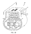
- FIG. 1B is a perspective view of the connector assembly of FIG. 1 , depicting the TPA device in a mated position.
- FIG. 2 is a perspective view of an outer housing of a connector assembly according to the present invention.
- FIGS. 3A and 3B are perspective views of an inner housing according to the present invention.
- FIGS. 4A and 4B are perspective views of a TPA device according to the present invention.
- FIG. 5A is a perspective view of a terminal for use with a connector assembly according to the present invention.
- FIG. 5B is a top plan view of the terminal of FIG. 5A .
- FIG. 5C is a cross-sectional view taken substantially along line II—II of FIG. 5B .
- FIG. 6 is a partially fragmented perspective view of the inner housing of FIGS. 3A and 3B and the TPA device of FIGS. 4A and 4B .
- FIG. 7A is a perspective view of the TPA device of FIGS. 4A and 4B coupled to the inner housing of FIGS. 3A and 3B , and in the pre-latched position.
- FIG. 7B is a perspective view similar to FIG. 7A , depicting the TPA device in the mated position.
- FIG. 8 is a partially fragmented cross-sectional view taken substantially along line I—I of FIG. 1B .
- FIG. 9A is a partially fragmented top plan view of the connector assembly of FIG. 1B .
- FIG. 9B is a cross-sectional view taken substantially along line III—III of FIG. 9A , depicting the TPA device in the pre-latched position.
- FIG. 10A is another partially fragmented top plan view of the connector assembly of FIG. 1B .
- FIG. 10B is a cross-sectional view taken substantially along line IV—IV of FIG. 10A , depicting the TPA device in the pre-latched position.
- FIG. 11A is a partially fragmented top plan view of the connector assembly of FIG. 1A .
- FIG. 11B is a cross-sectional view taken substantially along line V—V of FIG. 11A , depicting the TPA device in the mated position.
- a connector assembly 10 generally includes an outer housing 12 , an inner housing 14 , and a terminal position assurance (“TPA”) device 16 .
- TPA device 16 is coupled to inner housing 14 for movement between a pre-latched position (as shown in FIG. 1A ) and a mated position (as shown in FIG. 1B ). With TPA device 16 attached, inner housing 14 is received by outer housing 12 .
- a mating assembly (not shown) is connected to connector assembly 10 to form a sealed, electrical connection between terminals of assembly 10 and terminals of the mating assembly.
- an optional connector position assurance (“CPA”) device 17 may be attached to outer housing 12 to lock the mated assemblies in mating engagement with one another.
- Outer housing 12 is shown in FIG. 2 .
- outer housing 12 includes an upper wall 18 , a pair of side walls 20 , 22 , a rear wall 24 , and a lower wall 26 , which together substantially define an interior space 28 .
- Structural components of the mating assembly (not shown) and CPA device 17 are received by a plurality of openings and structural components of upper wall 18 , which will not be described in detail herein.
- Side wall 20 includes an outer surface (not shown) and an inner surface 32 .
- Side wall 22 similarly includes an outer surface 34 and an inner surface (not shown).
- Rear wall 24 forms an opening 38 configured to receive a portion of inner housing 14 when connector assembly 10 is assembled.
- Lower wall 26 includes an outer surface (not shown) and an inner surface 42 , and is integrally connected to side walls 20 , 22 . Together, upper wall 18 , side walls 20 , 22 , and lower wall 26 form a forward edge 44 of outer housing 12 . As shown, side walls 20 , 22 and lower wall 26 together have a substantially “C” shaped cross-section.
- inner housing 14 generally includes a rear body 46 , a forward body 48 , connected together at a guide wall 50 .
- Rear body 46 generally defines an interior space (not shown) through which wires connected to terminals installed in inner housing 14 extend for connection to the electronics of the application of connector assembly 10 .
- Forward body 48 includes an upper wall 52 , a lower wall 54 , side walls 56 , 58 , and forward wall 60 .
- Upper wall 52 includes a lug 62 having a cam surface 64 and a retention surface 66 configured to retain TPA device 16 in the pre-latched position and the mated position as will be further described below. As best shown in FIG.
- lower wall 54 substantially defines a first slot 68 and a second slot 70 , and includes a laterally extending overstress bar 71 that limits movement of latches included in inner housing 14 as will be further described below.
- First slot 68 extends substantially laterally across lower wall 54 in a direction that is substantially perpendicular to a longitudinal axis of the terminals housed by inner housing 14 as is further described below.
- First slot 68 includes a first end 72 , a second end 74 , and a pair of substantially parallel side edges 76 , 78 that extend between first end 72 and second end 74 .
- a support block 80 extends between side edges 76 , 78 and is integral with forward wall 60 .
- Support block 80 , upper wall 52 , and side walls 56 , 58 substantially define a pair of latch recesses 82 , 84 , each of which is accessible through first slot 68 .
- a latch 86 extends from upper wall 52 through latch recess 82 and a latch 88 extends from upper wall 52 through latch recess 84 .
- Second slot 70 includes a first end 90 , a second end 92 , a forward wall 94 ( FIG. 8 ), and a rearward wall 96 that is integral with guide wall 50 .
- forward wall 94 of second slot 70 includes a guide ridge 98 configured to guide TPA device 16 onto inner housing 14 as is further described below.
- Extending between side wall 56 and guide wall 50 is a first rib 100 having an upper surface 102 that extends partially into second slot 70 , a lower surface 104 , and an edge 106 .
- rib 100 is substantially perpendicular to both side wall 56 and guide wall 50 .
- a second rib 108 extends between side wall 58 and guide wall 50 .
- Rib 108 also includes an upper surface 110 , a lower surface 112 , and an edge 114 .
- rib 108 is substantially perpendicular to both side wall 58 and guide wall 50 , and extends substantially the entire length of side wall 58 between guide wall 50 and forward wall 60 .
- Forward wall 60 includes a protruding portion 116 and a recessed portion 118 .
- Protruding portion 116 includes a first opening 120 and a second opening 122 that extend into terminal chambers as is further described below.
- Recessed portion 118 similarly includes a first opening 124 that extends into latch recess 84 and a second opening 126 that extends into latch recess 82 .
- Guide wall 50 includes a forward surface 128 , a rearward surface 130 , and a peripheral edge 132 that substantially corresponds to the dimensions and contours of interior space 28 of outer housing 12 .
- Forward surface 128 includes a ridge 134 that extends substantially laterally along forward surface 128 to inhibit removal of TPA device 16 when coupled to inner housing 14 as is further described below.
- TPA device 16 generally includes an upper portion 136 , a lower portion 138 , a side wall 140 connecting upper portion 136 to lower portion 138 , and a front wall 142 , which together substantially define an interior space 143 .
- Upper portion 136 includes an upper wall 144 , and a pair of side walls 148 , 150 extending from upper wall 144 .
- Upper wall 144 includes a portion that extends farther rearwardly (as viewed in the figures) than side walls 148 , 150 to form a ledge 152 that is received between upper wall 52 of inner housing 14 and ridge 134 during installation of TPA device 16 onto inner housing 14 .
- Side wall 148 includes a pry slot 154 for use in removing TPA device 16 from inner housing 14 as is further described below.
- Lower portion 138 of TPA device 16 includes a lower wall 156 , a first retention block 158 , a second retention block 162 , and a third retention block 160 , all extending from lower wall 156 into interior space 143 .
- First retention block 158 includes side surfaces 164 , 166 , 168 , 170 and upper surface 172 .
- Third retention block 160 also includes side surfaces 174 , 176 , 178 and upper surface 182 . As shown, a portion of third retention block 160 opposite side surface 176 is integral with side wall 140 of TPA device 16 .
- Second retention block 162 includes a side surface 184 , a forward surface 186 , a rearward surface 188 , and an upper surface 190 .
- second retention block 162 opposite side surface 184 is integral with side wall 140 of TPA device 16 .
- a groove 192 is formed in forward surface 186 and side surface 184 , and extends substantially the entire length of second retention block 162 .
- a notch 194 is formed in forward surface 186 , rearward surface 188 , and upper surface 190 .
- Side wall 140 of TPA device 16 includes a cut-out 196 having a lower edge 198 that is substantially the same distance from lower wall 156 as upper surface 190 of second retention block 162 .
- Front wall 142 of TPA device 16 generally includes a first portion 200 and a second portion 202 , both occupying substantially the same plane.
- First portion 200 generally includes an upper segment 204 , a side segment 206 and a lower segment 208 .
- Upper segment 204 extends between and connects upper wall 144 , and side walls 148 , 150 of upper portion 136 , and includes a lower edge 209 .
- Side segment 206 includes an outer edge 210 that substantially conforms to the contour of side wall 32 of outer housing 12 , and an inner edge 212 .
- Lower segment 208 is connected to lower wall 156 and includes an upper edge 214 .
- second portion 202 of front wall 142 is spaced apart from lower segment 208 of first portion 200 , thereby forming a gap 216 .
- Second portion 202 includes a notch 218 and an upper edge 220 .
- Edges 209 , 212 , 214 , and 220 together substantially define a frame for receiving protruding portion 116 of inner housing 14 as is further described below.
- terminal 222 for use with connector assembly 10 is shown.
- terminal 222 is a 0.64 mm MQS clean body terminal, but various different types of terminals may be used consistent with the teachings of the present invention.
- Terminal 222 generally includes a receptacle 224 , and a wire portion 226 .
- Receptacle 224 includes an upper wall 228 , a lower wall 230 , an inner wall 231 , a pair of side walls 232 , 234 extending between upper wall 228 and lower wall 230 , a forward wall 236 , and a rearward wall 238 . As best shown in FIGS.
- upper wall 228 includes an aperture 240 .
- forward wall 236 forms an aperture 242 for receiving a mating terminal (not shown) as is further described below.
- Inner wall 231 extends between side walls 232 , 234 in substantially parallel relationship to upper wall 228 and lower wall 230 .
- Wire portion 226 is made of any of a variety of conductive materials and includes a forward segment 244 ( FIG. 5C ) that extends into and is welded or otherwise connected to the interior surfaces of receptacle 224 .
- Forward segment 244 includes a plurality of flexible contacts 246 having inner contact surfaces 248 that engage the exterior of the mating terminal (not shown) to provide electrical connection between terminal 222 and the mating terminal.
- Wire portion 226 further includes a first pair of conductor clamps 250 A, 250 B, and a second pair of conductor clamps 252 A, 252 B, all extending from a central wall 256 .
- clamps 250 A, 250 B are crimped toward one another, around the conductor, in a manner that is well-known in the art.
- clamps 252 A, 252 B are crimped around the conductor. In this manner, electrical connection is made between the conductor and terminal 222 .
- TPA device 16 is coupled to inner housing 14 in the following manner. As shown in FIG. 6 , TPA device 16 is aligned such that lower portion 138 will slide over lower wall 54 of inner housing 14 and upper portion 136 will slide over upper wall 52 of inner housing 14 . More particularly, from the position shown in FIG. 6 , TPA device 16 is moved axially in the direction of arrow 258 toward inner housing 14 to receive inner housing 14 substantially within interior space 143 . As TPA device 16 is moved axially, first retention block 158 and third retention block 160 move into first slot 68 , and second retention block 162 moves into second slot 70 .
- ledge 152 of TPA device 16 moves into a channel 135 formed between ridge 134 and upper wall 52 of inner housing 14 . Additionally, the frame defined by front wall 142 of TPA device 16 partially receives protruding portion 116 of inner housing forward wall 60 . Finally, groove 192 of TPA device second retention block 162 receives guide ridge 98 ( FIG. 8 ) of forward wall 94 of inner housing second slot 70 .
- TPA device 16 As TPA device 16 approaches its pre-latched position as shown in FIG. 7A , cam surface 64 of lug 62 ( FIG. 3A ) projecting from upper wall 52 of inner housing 14 engages upper wall 144 of TPA device 16 , causing upper portion 136 to flex slightly away from lower portion 138 .
- the clearance between ridge 134 of inner housing 14 and ledge 152 of TPA device 16 is sufficient to permit this amount of flexing, but substantially prevents excessive flexing of upper portion 136 away from inner housing 14 .
- lug 62 registers with first recess 137 formed in upper wall 144 , and TPA device 16 returns to its original, un-flexed state.
- first retention block 158 is positioned between latches 86 , 88 and third retention block 160 is positioned to the right of latch 86 as viewed in FIG. 7A , latches 86 , 88 may be flexed upwardly toward overstress bar 71 out of engagement with respective terminals 222 to permit removal of the terminals through rear body 46 of inner housing 14 , as will be further described below.
- Overstress bar 71 prevents excessive flexing of latches 86 , 88 and the accompanying damage that may result.
- second retention block 162 has not been moved sufficiently in the direction of arrow 258 to prevent removal of terminal 222 associated with latch 88 and notch 194 of second retention block 162 provides clearance for removal of terminal 222 associated with latch 86 .
- cam surface 64 of lug 62 causes upper portion 136 of TPA device 16 to flex slightly away from inner housing 14 , and lug 62 moves out of first recess 137 .
- lug 62 registers with second recess 139 , and lower portion 138 returns to its original, unflexed state as lug 62 enters second recess 139 .
- retention surface 66 of lug 62 engages the side wall of second recess 139 and substantially inhibits movement of TPA device 16 in the direction of arrow 260 . As shown in FIG.
- second portion 202 of front wall 142 substantially covers or obstructs access to latch 88 through opening 124 .
- lower segment 208 of first portion 200 substantially obstructs access to latch 86 through opening 126 .
- first retention block 158 substantially inhibits movement of latch 88 out of its unflexed position, and therefore disengagement from the corresponding terminal 222
- third retention block 160 substantially inhibits movement of latch 86 out of its unflexed position, and therefore disengagement from the corresponding terminal 222
- second retention block 162 substantially inhibits removal of terminals 222 by engaging rearward walls 238 of terminals 222 if terminals 222 are moved in the direction of arrow 264 of FIG. 8 as is further described below.
- FIG. 8 is a cross-sectional view taken substantially along line I—I of FIG. 1B , TPA device 16 is in the mated position, and the TPA device 16 /inner housing 14 assembly is installed in outer housing 12 . Additionally, terminal 222 is installed in inner housing 14 . This figure most clearly depicts the retention features provided by first retention block 158 , second retention block 162 , and third retention block 160 . Terminal 222 is installed in inner housing 14 by urging terminal 222 in the direction of arrow 262 though rear body 46 and into forward body 48 . This installation is performed with TPA device 16 coupled to inner housing 14 in the pre-latched position.
- receptacle 224 of terminal 222 engages a lug 257 extending from latch 86 , causing latch 86 to deflect downwardly as viewed in the figure into latch recess 82 .
- latch 86 returns to its unflexed position, and lug 257 enters aperture 240 ( FIG. 5B ) of receptacle upper wall 228 .
- lug 257 ensures proper location of terminal 222 and inhibits movement of terminal 222 in the direction of arrow 264 by engagement with the edge of aperture 240 . Sufficient force, however, would tend to deform or flex latch 86 out of engagement with receptacle 224 .
- third retention block 160 is positioned in first slot 68 directly below (as viewed in the figure) latch 86 and lug 257 . Accordingly, third retention block 160 substantially prevents such flexing of latch 86 in a downward direction.
- second retention block 162 inhibits movement of terminal 222 in the direction of arrow 264 . More specifically, second retention block 162 is positioned in second slot 70 such that forward surface 186 is positioned directly behind (as viewed in the figure) rearward wall 238 of terminal 222 . Thus, forward surface 186 would engage rearward wall 238 if sufficient force is applied to terminal 222 , thereby substantially preventing removal of terminal 222 in the direction of arrow 264 . It should be understood, of course, that first retention block 158 ( FIG. 4B ) interacts with latch 88 , and second retention block 162 interacts with the corresponding terminal 222 (not shown) in a similar fashion.
- TPA device 16 would not be movable to its mated position. More specifically, if forward wall 236 of receptacle 224 were spaced apart from opening 122 , lug 257 would not register with aperture 240 . As such, latch 86 would be flexed downwardly. Consequently, TPA device 16 could not be moved to its mated position because third retention block 160 would engage latch 86 , which would prevent further movement of TPA device 16 . TPA device 16 , therefore, provides a mechanism for detecting partially inserted terminals 222 .
- FIGS. 9A through 11B further depict the various features of connector assembly 10 .
- TPA device 16 and inner housing 14 are installed in outer housing 12 .
- TPA device 16 is coupled to inner housing 14 , but shown in the pre-latched position.
- Cross-section line III—III is taken through TPA device 16 between front wall 142 and first and third retention blocks 158 , 160 .
- lug 257 of latch 86 is positioned in aperture 240 (not shown) of terminal 222 associated with second opening 122
- lug 257 of latch 88 is positioned in aperture 240 (not shown) of terminal 222 associated with first opening 120 .
- third retention block 160 is not positioned under latch 86 and first retention block 158 (not shown) is not positioned under latch 88 .
- Lug 62 of inner housing 14 is shown within first recess 137 .
- FIG. 9A further shows overstress bar 71 extending below latches 86 , 88 to limit the extent of downward flexing of latches 86 , 88 .
- FIGS. 10A and 10B also depict TPA device 16 in its pre-latched position coupled to inner housing 14 .
- cross-section line IV—IV is taken through TPA device 16 such that it substantially bisects first and third retention blocks 158 , 160 .
- first retention block 158 is not yet positioned under latch 88
- third retention block 160 is not yet positioned under latch 86 .
- TPA device 16 is depicted in its mated position.
- Cross-section line V—V is taken at the same location as line IV—IV of FIGS. 10A and 10B .
- first retention block 158 is positioned under latch 88 and third retention block 160 is positioned under latch 86 .
- latches 86 , 88 are substantially inhibited from flexing downwardly as viewed in the figures. Consequently, lugs 257 of latches 86 , 88 remain within apertures 240 (not shown) of terminals 222 to prevent movement of terminals 222 .
- second retention block 162 (not shown) is positioned behind wall 238 (not shown) of terminals 222 to inhibit removal of terminals 222 as described above in reference to FIG. 8 .
- Terminals 222 may be removed from inner housing 14 by first moving TPA device 16 to its pre-latched position as shown in FIG. 1A .
- a technician may insert a tool into pry slot 154 of side wall 148 of TPA upper portion 136 and urge upper portion 136 slightly away (downwardly as viewed in the figures) from inner housing 14 .
- upper portion 136 is moved sufficiently away from upper wall 52 of inner housing 14 that lug 62 ( FIG. 3A ) is withdrawn from second recess 139 ( FIG. 6 ) of TPA upper wall 144 .
- TPA device 16 may then be shifted in the direction of arrow 260 until lug 62 registers with first recess 137 .
- TPA device 16 may then be permitted to return to its original, unflexed state such that lug 62 enters first recess 137 , thereby retaining TPA device 16 in its pre-latched position as shown in FIGS. 1A and 7B .
- latches 86 , 88 may flex away from terminals 222 such that lugs 257 of latches 86 , 88 withdraw from apertures 240 of terminal receptacles 224 . This flexing can occur as first retention block 158 is no longer positioned under latch 88 and third retention block 160 is no longer positioned under latch 86 .
- front wall 142 no longer obstructs access to first opening 124 or second opening 126 . Accordingly, a technician may insert a tool into openings 124 , 126 to flex the respective latches 88 , 86 out of engagement with terminals 222 . Finally, the technician may pull terminals 222 in the direction of arrow 264 ( FIG. 8 ) to remove them.
Landscapes
- Details Of Connecting Devices For Male And Female Coupling (AREA)
- Connector Housings Or Holding Contact Members (AREA)
Priority Applications (8)
| Application Number | Priority Date | Filing Date | Title |
|---|---|---|---|
| US11/147,090 US7044808B1 (en) | 2005-06-07 | 2005-06-07 | Connector assembly with terminal position assurance device |
| KR1020077028442A KR100939700B1 (ko) | 2005-06-07 | 2006-06-07 | 단자 위치 보장 장치를 구비하는 커넥터 조립체 |
| PCT/US2006/022030 WO2006133244A1 (en) | 2005-06-07 | 2006-06-07 | Connector assembly with terminal position assurance device |
| EP06772370A EP1889332B1 (en) | 2005-06-07 | 2006-06-07 | Connector assembly with terminal position assurance device |
| CA2609775A CA2609775C (en) | 2005-06-07 | 2006-06-07 | Connector assembly with terminal position assurance device |
| CN2006800249357A CN101218714B (zh) | 2005-06-07 | 2006-06-07 | 带有接线端位置保证装置的连接器组件 |
| MX2007015451A MX2007015451A (es) | 2005-06-07 | 2006-06-07 | Ensamble conector con dispositivo que asegura la posicion de terminal. |
| JP2008515850A JP4963702B2 (ja) | 2005-06-07 | 2006-06-07 | 端子位置保証装置を有するコネクタ組立体 |
Applications Claiming Priority (1)
| Application Number | Priority Date | Filing Date | Title |
|---|---|---|---|
| US11/147,090 US7044808B1 (en) | 2005-06-07 | 2005-06-07 | Connector assembly with terminal position assurance device |
Publications (1)
| Publication Number | Publication Date |
|---|---|
| US7044808B1 true US7044808B1 (en) | 2006-05-16 |
Family
ID=36318031
Family Applications (1)
| Application Number | Title | Priority Date | Filing Date |
|---|---|---|---|
| US11/147,090 Active US7044808B1 (en) | 2005-06-07 | 2005-06-07 | Connector assembly with terminal position assurance device |
Country Status (8)
| Country | Link |
|---|---|
| US (1) | US7044808B1 (ja) |
| EP (1) | EP1889332B1 (ja) |
| JP (1) | JP4963702B2 (ja) |
| KR (1) | KR100939700B1 (ja) |
| CN (1) | CN101218714B (ja) |
| CA (1) | CA2609775C (ja) |
| MX (1) | MX2007015451A (ja) |
| WO (1) | WO2006133244A1 (ja) |
Cited By (13)
| Publication number | Priority date | Publication date | Assignee | Title |
|---|---|---|---|---|
| WO2008023009A1 (en) * | 2006-08-21 | 2008-02-28 | Fci | Electrical connector and housing thereof |
| US20090186523A1 (en) * | 2008-01-23 | 2009-07-23 | Fci Americas Technology, Inc. | Electrical connector |
| US20090280696A1 (en) * | 2008-05-07 | 2009-11-12 | Tyco Electronics Corporation | Remote detection of partially seated electrical terminal |
| US7628648B1 (en) | 2008-11-14 | 2009-12-08 | J. S. T. Corporation | Terminal position assurance device and a connector assembly employing the same |
| US20090311918A1 (en) * | 2008-06-13 | 2009-12-17 | Tyco Electronics Corporation | Electrical connector having alternative inner housings |
| US20150056829A1 (en) * | 2012-03-16 | 2015-02-26 | Delphi International Operations Luxembourg, S.A.R.L. | Electrical connector |
| US9640895B1 (en) * | 2016-06-14 | 2017-05-02 | Te Connectivity Corporation | Electrical connector having a TPA |
| US9935389B1 (en) | 2017-02-23 | 2018-04-03 | Sumitomo Wiring Systems, Ltd. | Inline connector housing assemblies with removable TPA |
| US10847916B2 (en) * | 2019-03-15 | 2020-11-24 | Yazaki Corporation | Connector |
| US20210098930A1 (en) * | 2019-10-01 | 2021-04-01 | Aptiv Technologies Limited | Connector assembly |
| US11095064B2 (en) | 2019-03-18 | 2021-08-17 | Yazaki Corporation | Connector structure |
| US11189951B2 (en) * | 2019-03-15 | 2021-11-30 | Yazaki Corporation | Connector |
| US20220029336A1 (en) * | 2020-07-24 | 2022-01-27 | Aptiv Technologies Limited | Coaxial connector assembly |
Families Citing this family (6)
| Publication number | Priority date | Publication date | Assignee | Title |
|---|---|---|---|---|
| US8926363B2 (en) * | 2012-03-02 | 2015-01-06 | Tyco Electronics Corporation | Electrical connector assembly |
| JP6539283B2 (ja) * | 2014-01-30 | 2019-07-03 | ティーイー コネクティビティ インディア プライベート リミテッドTe Connectivity India Private Limited | 多機能コネクタ位置決め保証デバイス |
| KR102591645B1 (ko) * | 2015-10-13 | 2023-10-20 | 타이코에이엠피 주식회사 | 커넥터 어셈블리 |
| US10461457B1 (en) * | 2018-07-23 | 2019-10-29 | Yazaki North America, Inc. | Connector housing and terminal position assurance joint clip site |
| CN218448556U (zh) * | 2022-09-09 | 2023-02-03 | 泰科电子(苏州)有限公司 | 连接器模块、连接器和连接器组件 |
| CN117353080B (zh) * | 2023-11-01 | 2024-03-22 | 浙江珠城科技股份有限公司 | 一种小间距板端连接器 |
Citations (2)
| Publication number | Priority date | Publication date | Assignee | Title |
|---|---|---|---|---|
| US6599150B1 (en) * | 2002-03-22 | 2003-07-29 | Tyco Electronics Corporation | Electrical connector assembly |
| US6695651B2 (en) * | 2001-06-22 | 2004-02-24 | Sumitomo Wiring Systems, Ltd. | Connector |
Family Cites Families (9)
| Publication number | Priority date | Publication date | Assignee | Title |
|---|---|---|---|---|
| EP0743711B1 (en) * | 1995-05-17 | 2001-03-21 | Sumitomo Wiring Systems, Ltd. | Male connector |
| US6062906A (en) * | 1998-08-31 | 2000-05-16 | Sumitomo Wiring Systems, Ltd. | Electrical connector and retaining member therefor |
| JP2001043924A (ja) * | 1999-07-28 | 2001-02-16 | Sumitomo Wiring Syst Ltd | コネクタ |
| JP4058903B2 (ja) * | 2000-12-19 | 2008-03-12 | 住友電装株式会社 | コネクタ |
| US6551145B2 (en) * | 2000-12-19 | 2003-04-22 | Sumitomo Wiring Systems, Ltd. | Connector |
| JP3755431B2 (ja) * | 2001-06-22 | 2006-03-15 | 住友電装株式会社 | コネクタ |
| KR101000152B1 (ko) * | 2002-09-25 | 2010-12-10 | 미츠비시 덴센 고교 가부시키가이샤 | 전기 커넥터 |
| EP1408588A1 (de) * | 2002-10-09 | 2004-04-14 | Delphi Technologies, Inc. | Elektrischer Verbinder |
| DE10332892B4 (de) * | 2003-07-19 | 2011-01-27 | Leopold Kostal Gmbh & Co. Kg | Kammergehäuse zur Ausbildung eines elektrischen Steckverbindungsteils |
-
2005
- 2005-06-07 US US11/147,090 patent/US7044808B1/en active Active
-
2006
- 2006-06-07 WO PCT/US2006/022030 patent/WO2006133244A1/en active Application Filing
- 2006-06-07 EP EP06772370A patent/EP1889332B1/en active Active
- 2006-06-07 JP JP2008515850A patent/JP4963702B2/ja active Active
- 2006-06-07 MX MX2007015451A patent/MX2007015451A/es active IP Right Grant
- 2006-06-07 KR KR1020077028442A patent/KR100939700B1/ko not_active IP Right Cessation
- 2006-06-07 CA CA2609775A patent/CA2609775C/en not_active Expired - Fee Related
- 2006-06-07 CN CN2006800249357A patent/CN101218714B/zh active Active
Patent Citations (2)
| Publication number | Priority date | Publication date | Assignee | Title |
|---|---|---|---|---|
| US6695651B2 (en) * | 2001-06-22 | 2004-02-24 | Sumitomo Wiring Systems, Ltd. | Connector |
| US6599150B1 (en) * | 2002-03-22 | 2003-07-29 | Tyco Electronics Corporation | Electrical connector assembly |
Cited By (26)
| Publication number | Priority date | Publication date | Assignee | Title |
|---|---|---|---|---|
| CN101517838B (zh) * | 2006-08-21 | 2012-04-25 | Fci连接器新加坡有限公司 | 电连接器及其壳体 |
| WO2008023009A1 (en) * | 2006-08-21 | 2008-02-28 | Fci | Electrical connector and housing thereof |
| US20110165794A1 (en) * | 2008-01-23 | 2011-07-07 | Fci Americas Technology, Inc. | Electrical connector |
| US20090186523A1 (en) * | 2008-01-23 | 2009-07-23 | Fci Americas Technology, Inc. | Electrical connector |
| WO2009094319A1 (en) * | 2008-01-23 | 2009-07-30 | Fci | Electrical connector |
| US8262410B2 (en) | 2008-01-23 | 2012-09-11 | Fci Automotive Holding | Electrical connector |
| EP2235799A1 (en) * | 2008-01-23 | 2010-10-06 | Fci | Electrical connector |
| CN101926058A (zh) * | 2008-01-23 | 2010-12-22 | Fci公司 | 电连接器 |
| US7914327B2 (en) | 2008-01-23 | 2011-03-29 | Fci Americas Technology, Inc. | Electrical connector |
| EP2235799A4 (en) * | 2008-01-23 | 2011-06-22 | Fci Automotive Holding | ELECTRICAL CONNECTOR |
| US20090280696A1 (en) * | 2008-05-07 | 2009-11-12 | Tyco Electronics Corporation | Remote detection of partially seated electrical terminal |
| US7867028B2 (en) | 2008-05-07 | 2011-01-11 | Tyco Electronics Corporation | Remote detection of partially seated electrical terminal |
| US7780484B2 (en) | 2008-06-13 | 2010-08-24 | Tyco Electronics Corporation | Electrical connector having alternative inner housings |
| US20090311918A1 (en) * | 2008-06-13 | 2009-12-17 | Tyco Electronics Corporation | Electrical connector having alternative inner housings |
| US7628648B1 (en) | 2008-11-14 | 2009-12-08 | J. S. T. Corporation | Terminal position assurance device and a connector assembly employing the same |
| US20150056829A1 (en) * | 2012-03-16 | 2015-02-26 | Delphi International Operations Luxembourg, S.A.R.L. | Electrical connector |
| US9276345B2 (en) * | 2012-03-16 | 2016-03-01 | Delphi International Operations Luxembourg S.A.R.L. | Electrical connector |
| US9640895B1 (en) * | 2016-06-14 | 2017-05-02 | Te Connectivity Corporation | Electrical connector having a TPA |
| US9935389B1 (en) | 2017-02-23 | 2018-04-03 | Sumitomo Wiring Systems, Ltd. | Inline connector housing assemblies with removable TPA |
| US10847916B2 (en) * | 2019-03-15 | 2020-11-24 | Yazaki Corporation | Connector |
| US11189951B2 (en) * | 2019-03-15 | 2021-11-30 | Yazaki Corporation | Connector |
| US11095064B2 (en) | 2019-03-18 | 2021-08-17 | Yazaki Corporation | Connector structure |
| US20210098930A1 (en) * | 2019-10-01 | 2021-04-01 | Aptiv Technologies Limited | Connector assembly |
| US11515660B2 (en) * | 2019-10-01 | 2022-11-29 | Aptiv Technologies Limited | Electrical connector assembly with retaining device |
| US20220029336A1 (en) * | 2020-07-24 | 2022-01-27 | Aptiv Technologies Limited | Coaxial connector assembly |
| US11545777B2 (en) * | 2020-07-24 | 2023-01-03 | Aptiv Technologies Limited | Coaxial connector assembly |
Also Published As
| Publication number | Publication date |
|---|---|
| KR100939700B1 (ko) | 2010-02-01 |
| CA2609775C (en) | 2010-08-03 |
| CN101218714A (zh) | 2008-07-09 |
| EP1889332A1 (en) | 2008-02-20 |
| EP1889332B1 (en) | 2011-08-17 |
| WO2006133244A1 (en) | 2006-12-14 |
| JP2008543026A (ja) | 2008-11-27 |
| MX2007015451A (es) | 2008-02-19 |
| CA2609775A1 (en) | 2006-12-14 |
| CN101218714B (zh) | 2010-05-19 |
| JP4963702B2 (ja) | 2012-06-27 |
| KR20080006014A (ko) | 2008-01-15 |
Similar Documents
| Publication | Publication Date | Title |
|---|---|---|
| US7044808B1 (en) | Connector assembly with terminal position assurance device | |
| US7559808B2 (en) | Connector | |
| US5672073A (en) | Connector having engagement detecting device | |
| US6942510B2 (en) | Connector and a connector system | |
| US8366493B2 (en) | Connector having a retainer with a plate shaped detection part | |
| US5273456A (en) | Mate sensing connector system | |
| US6716069B2 (en) | Connector with a housing and a retainer held securely on the housing | |
| US5618201A (en) | Connector having engagement detecting device | |
| US6659797B2 (en) | Connector with resiliently deflectable lock arm | |
| EP1962390B1 (en) | A connector and a connector assembly | |
| US7014511B2 (en) | Electrical connector | |
| US7581969B2 (en) | Connector with auxiliary housing having inverted insertion preventing portion | |
| US7172468B2 (en) | Divided connector and method of assembling it | |
| EP1801925B1 (en) | A connector | |
| EP1033788B1 (en) | Connector with secondary locking | |
| EP1077513B1 (en) | A terminal fitting, a connector housing and a connector comprising the same | |
| US11791584B2 (en) | Connector having improved holding force for retainer | |
| US6368164B1 (en) | Connector with a retainer | |
| US7753613B2 (en) | Connector | |
| US20020072277A1 (en) | Connector | |
| US7063577B2 (en) | Split-type connector assembly and method of assembling it | |
| US6835106B2 (en) | Connector, a connector assembly, a jig, and a method for withdrawing a terminal in a connector | |
| CN111755879B (zh) | 用于连接器的壳体 | |
| CN112038811B (zh) | 壳体 | |
| JP7460470B2 (ja) | コネクタ |
Legal Events
| Date | Code | Title | Description |
|---|---|---|---|
| AS | Assignment |
Owner name: TYEO ELECTRONICS CORPORATION, PENNSYLVANIA Free format text: ASSIGNMENT OF ASSIGNORS INTEREST;ASSIGNORS:FOLTZ, KEITH R.;BUCHTER, BRADLEY S.;REEL/FRAME:016675/0230 Effective date: 20050420 |
|
| STCF | Information on status: patent grant |
Free format text: PATENTED CASE |
|
| FPAY | Fee payment |
Year of fee payment: 4 |
|
| FPAY | Fee payment |
Year of fee payment: 8 |
|
| AS | Assignment |
Owner name: TE CONNECTIVITY CORPORATION, PENNSYLVANIA Free format text: CHANGE OF NAME;ASSIGNOR:TYCO ELECTRONICS CORPORATION;REEL/FRAME:041350/0085 Effective date: 20170101 |
|
| MAFP | Maintenance fee payment |
Free format text: PAYMENT OF MAINTENANCE FEE, 12TH YEAR, LARGE ENTITY (ORIGINAL EVENT CODE: M1553) Year of fee payment: 12 |
|
| AS | Assignment |
Owner name: TE CONNECTIVITY SERVICES GMBH, SWITZERLAND Free format text: CHANGE OF ADDRESS;ASSIGNOR:TE CONNECTIVITY SERVICES GMBH;REEL/FRAME:056514/0015 Effective date: 20191101 Owner name: TE CONNECTIVITY SERVICES GMBH, SWITZERLAND Free format text: ASSIGNMENT OF ASSIGNORS INTEREST;ASSIGNOR:TE CONNECTIVITY CORPORATION;REEL/FRAME:056514/0048 Effective date: 20180928 |
|
| AS | Assignment |
Owner name: TE CONNECTIVITY SOLUTIONS GMBH, SWITZERLAND Free format text: MERGER;ASSIGNOR:TE CONNECTIVITY SERVICES GMBH;REEL/FRAME:060885/0482 Effective date: 20220301 |