EP1962390B1 - A connector and a connector assembly - Google Patents
A connector and a connector assembly Download PDFInfo
- Publication number
- EP1962390B1 EP1962390B1 EP08002664.4A EP08002664A EP1962390B1 EP 1962390 B1 EP1962390 B1 EP 1962390B1 EP 08002664 A EP08002664 A EP 08002664A EP 1962390 B1 EP1962390 B1 EP 1962390B1
- Authority
- EP
- European Patent Office
- Prior art keywords
- receptacle
- housing
- main body
- protection wall
- moving plate
- Prior art date
- Legal status (The legal status is an assumption and is not a legal conclusion. Google has not performed a legal analysis and makes no representation as to the accuracy of the status listed.)
- Expired - Fee Related
Links
Images


Classifications
-
- H—ELECTRICITY
- H01—ELECTRIC ELEMENTS
- H01R—ELECTRICALLY-CONDUCTIVE CONNECTIONS; STRUCTURAL ASSOCIATIONS OF A PLURALITY OF MUTUALLY-INSULATED ELECTRICAL CONNECTING ELEMENTS; COUPLING DEVICES; CURRENT COLLECTORS
- H01R13/00—Details of coupling devices of the kinds covered by groups H01R12/70 or H01R24/00 - H01R33/00
- H01R13/62—Means for facilitating engagement or disengagement of coupling parts or for holding them in engagement
- H01R13/629—Additional means for facilitating engagement or disengagement of coupling parts, e.g. aligning or guiding means, levers, gas pressure electrical locking indicators, manufacturing tolerances
- H01R13/62933—Comprising exclusively pivoting lever
-
- H—ELECTRICITY
- H01—ELECTRIC ELEMENTS
- H01R—ELECTRICALLY-CONDUCTIVE CONNECTIONS; STRUCTURAL ASSOCIATIONS OF A PLURALITY OF MUTUALLY-INSULATED ELECTRICAL CONNECTING ELEMENTS; COUPLING DEVICES; CURRENT COLLECTORS
- H01R13/00—Details of coupling devices of the kinds covered by groups H01R12/70 or H01R24/00 - H01R33/00
- H01R13/44—Means for preventing access to live contacts
- H01R13/447—Shutter or cover plate
- H01R13/453—Shutter or cover plate opened by engagement of counterpart
- H01R13/4538—Covers sliding or withdrawing in the direction of engagement
Definitions
- the present invention relates to a connector and to a connector assembly.
- a connector provided with a moving plate has been conventionally known (see, for example, Japanese Unexamined Patent Publication No. 2006-196225 ).
- This connector is provided with a male housing including a tubular receptacle and a female housing fittable into the receptacle from front, and the moving plate is so accommodated in the receptacle as to be movable in forward and backward directions.
- the moving plate includes a plate-like main body formed with a plurality of positioning holes. Before the male housing is connected with the female housing, the leading ends of male terminal fittings are inserted through the positioning holes to project from the front surface of the main body. At this initial position, a probe pin is pressed against the leading ends of the male terminal fittings projecting from the front surface of the main body for an electrical connection test.
- EP 1 257 013 A1 discloses a terminal fitting and a lever type-connector comprising a moving plate movable along a connecting direction of two connector housings.
- the moving plate comprises a tubular guide wall portion projecting at an outer peripheral edge of the moving plate.
- the present invention was developed in view of the above situation, and an object thereof is to prevent male terminal fittings from being deformed in a connector provided with a moving plate.
- a connector comprising:
- the protection wall includes at least a pair of opposite walls arranged to extend substantially along two opposite sides of the main body.
- a corner portion of the mating housing comes into contact with the pair of opposite walls while crossing over the terminal fittings arranged between the opposite walls if the mating housing is inserted in an improper posture into the receptacle at the initial position.
- the protection wall is arranged to surround a hole group including the plurality of positioning holes.
- the connector further comprises a movable member which can be operated to perform or assist the connection of the housing with the mating housing.
- the moving plate is displaced by the operation of the movable member.
- a connector assembly comprising a connector according to the invention or a preferred embodiment thereof comprising a housing having a receptacle and a mating connector connectable therewith, the mating connector comprising a mating housing at least partly insertable into the receptacle.
- the protection wall includes at least a pair of opposite walls arranged to extend substantially along two opposite sides of the main body and wherein a corner portion of the mating housing comes into contact with the pair of opposite walls while crossing over the terminal fittings arranged between the opposite walls if the mating housing is inserted in an improper posture into the receptacle at the initial position.
- a movable member is provided on either one of the housing or the mating housing, wherein the movable member can be operated to perform or assist the connection of the housing with the mating housing.
- a connector assembly comprising:
- the projecting end of the protection wall is located at the same position as or more forward than the leading end positions of the male terminal fittings at the initial position, the contact of the corner portion with the leading ends of the male terminal fittings can be reliably avoided when the corner portion of the female housing in the improper posture comes into contact with the projecting end of the protection wall.
- the protection wall includes at least a pair of opposite walls arranged to extend along two opposite sides of the main body, and a corner portion of the female housing comes into contact with the pair of opposite walls while crossing over the male terminal fittings arranged between the opposite walls if the female housing is inserted in an improper posture into the receptacle at the initial position.
- the corner portion of the female housing comes into contact with the pair of opposite walls while crossing over the male terminal fittings arranged between the opposite walls.
- the corner portion of the female housing comes into contact with the leading ends of the male terminal fittings arranged between the both opposite walls and the deformation of the male terminal fittings can be more reliably prevented.
- the protection wall is arranged to surround a hole group including the plurality of positioning holes.
- the protection wall is arranged to surround the hole group made up of the plurality of positioning holes, the strength of the main body can be increased and the plastic deformation thereof due to an external factor can be prevented.
- a connector of this embodiment is provided with a male housing 10 and a female housing 60 connectable with each other along connecting and separating directions CSD according to an operation or movement of a movable member (preferably the rotation of a lever 80), and a moving plate 40 to be mounted into the male housing 10.
- a movable member preferably the rotation of a lever 80
- a moving plate 40 to be mounted into the male housing 10.
- sides of the both housings 10, 60 to be connected are referred to as front sides concerning forward and backward directions in the following description.
- the female housing 60 is made e.g. of synthetic resin and preferably substantially in the form of a block narrow and long in height direction (vertical direction in FIG. 1 ) as a whole, and one or more cavities 61 for at least partly accommodating one or more female terminal fittings 75 are formed preferably substantially side by side in height direction at one or more stages inside the female housing 60 as shown in FIG. 2 .
- the front openings of the cavities 61 preferably are substantially aligned in the front surface of the female housing 60, and this front surface is recessed substantially in U-shape around groups of the cavities 61 as collections of the respective cavities 61 to form one or more recessed portions 62 slightly retracted from the front openings of the cavities 61.
- at least one protection wall 41 provided on or at the moving plate 40 is at least partly fittable into these recessed portions 62 upon connecting the two housings 10, 60.
- a wire cover 63 is mounted on or to (preferably a rear part of) the female housing 60, and one or more draw-out directions of wires 76 connected with the female terminal fittings 75 are specified or defined by this wire cover 63.
- one or more, preferably a plurality of connection ribs 64 extending substantially in forward and backward directions are formed on the outer surface of the female housing 60 as shown in FIG. 1 . A connecting operation of the two housings 10, 60 is guided and an erroneous connection of the two housings 10, 60 is prevented by the respective connection rib(s) 64.
- the male housing 10 is made e.g. of synthetic resin and includes a terminal holding portion 11 (preferably substantially in the form of a block narrow and long in height direction) and a receptacle 12 (preferably substantially in the form of a rectangular tube) projecting substantially forward from or near the peripheral edge of the terminal holding portion 11.
- a terminal holding portion 11 preferably substantially in the form of a block narrow and long in height direction
- a receptacle 12 preferably substantially in the form of a rectangular tube projecting substantially forward from or near the peripheral edge of the terminal holding portion 11.
- One or more terminal main bodies 16 of one or more, preferably a plurality of male terminal fittings 15 are at least partly accommodated preferably substantially side by side in height direction in the terminal holding portion 11.
- one or more (preferably substantially narrow and long) tabs 17 integral or unitary to and projecting substantially forward from the terminal main bodies 16 are at least partly arranged in the receptacle 12 and are connectable with the corresponding female terminal fittings 75.
- One or more, preferably a pair of supporting shafts 13 for supporting the lever 80 project in one or more intermediate positions (preferably substantially in middle parts) of the (preferably substantially opposite) side surface(s) of the receptacle 12 in height direction, and these side surfaces preferably are cut straight from the front opening edge of the receptacle 12 toward the supporting shafts 13 to form one ormore, preferably a pair of escape grooves 14.
- the first cam pins 65 at least partly enter the corresponding escape grooves 14 at the time of connecting the two housings 10, 60.
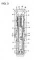
- the lever 80 (as a preferred movable member) is made e.g. of synthetic resin, includes a pair of lateral (left and right) substantially plate-like arms 81 and an operable portion 82 connecting the both arms 81 and is gate-shaped as a whole as shown in FIG. 3 .
- each arm 81 is formed with a bearing hole 83 for at least partly receiving the corresponding supporting shaft 13.
- a lever 80 By engaging the supporting shafts 13 with the bearing holes 83, such a lever 80 is movable (preferably rotatable or pivotable about the engaged positions) between a standby position where the arms 81 stand up in height direction and a connection position where the arms 81 cross the opposite outer side surfaces of the female housing 60 and the operable portion 82 is located behind the wire cover 63. Further, an arcuate cam groove 84 substantially centered on the bearing hole 83 is so formed in the inner surface of each arm 81 as to make an opening at the peripheral edge of the arm 81.
- the moving plate 40 is likewise made e.g. of synthetic resin, at least partly arranged in the receptacle 12 and functions to position the respective tabs 17 with respect to height and/or width directions.
- This moving plate 40 is movable substantially in forward and backward directions (directions substantially parallel to connecting and separating directions CSD of the two housings 10, 60) in the receptacle 12, and includes a (preferably substantially rectangular plate-like) main body 42 substantially perpendicular to the moving direction of the moving plate 40 and a surrounding wall 43 (preferably substantially in the form of a rectangular tube) projecting forward from at least part of the peripheral edge of the main body 42.
- the outer circumferential surface of the surrounding wall 43 slides substantially in contact with the inner circumferential surface of the receptacle 12.
- the inner surface of the surrounding wall 43 is formed with one or more receiving grooves 44 at positions substantially corresponding to the connection ribs 64.
- the outer surfaces of the surrounding wall 43 are formed to bulge outward at positions corresponding to the receiving grooves 44, and the inner surfaces of the receptacle 12 are formed with recessed portions 19 for allowing the bulged portions of the surrounding wall 43 to escape.
- One or more, preferably a pair of introducing grooves 45 extending substantially in forward and backward directions substantially in intermediate position(s) (preferably substantially in the middles) of the (preferably substantially opposite) outer side surface(s) of the surrounding wall 43 in height direction and making opening(s) in the front edge of the surrounding wall 43 are so formed as to be able to at least partly receive the first cam pins 65.
- the (preferably substantially opposite) outer side surface(s) of the surrounding wall 43 are formed with one or more second cam pins 46 projecting while crossing over the introducing groove(s) 45.
- the second cam pins 46 preferably are substantially gate-shaped when viewed from front, and the first cam pins 65 are at least partly fittable thereinto.
- the second cam pins 46 are at least partly fitted or inserted into the cam grooves 84 of the lever 80 while being united or integrally connected with the first cam pins 65 until the two housings 10, 60 are completely connected. Thereafter, the female housing 60 and the moving plate 40 integrally move as the movable member is operated, preferably the lever 80 is rotated or pivoted.
- One or more, preferably an array of positioning holes 47 enabling the insertion of the respective tab(s) 17 is formed to penetrate the main body 42. More specifically, the one or more positioning holes 47 guide the respective tab(s) 17 preferably by being widened toward the rear surface of the main body 42 while ensuring the positioning of the respective tabs 17 preferably by being narrowed toward the front surface of the main body 42.
- Such a moving plate 40 moves from an initial mount position IP (hereinafter, "initial position") where the main body 42 is distanced from the back surface of the receptacle 12 to a position at the end of the connecting operation (end position) where the main body 42 is substantially in contact with the back surface of the receptacle 12 during the connecting operation of the two housings 10, 60.
- the tabs 17 are kept in the positioning holes 47 preferably at any position along a moving path of the moving plate 40, whereby the tabs 17 can be reliably positioned.
- the leading ends of the tabs 17 project from the front surface of the main body 42 to substantially face toward a connection surface as shown in FIG. 5 and, in this state, an unillustrated electrical connection test is or may be conducted.
- the leading end positions of the respective tabs 17 in the receptacle 12 are substantially aligned at the same position in forward and backward directions (or the connecting and separating directions CSD).
- At least one protection wall 41 is formed on the front surface (surface substantially facing the female housing 60) of the main body 42 to project at least partly around hole groups 48 as collections of the positioning holes 47.
- the protection wall 41 surrounds the hole groups 48 at least partly, preferably substantially over the entire circumferences, and preferably is comprised of substantially rectangular walls when viewed from front (see FIG. 3 ) for at least partly surrounding a plurality of respective hole groups 48 divided in height direction.
- the protection wall 41 is comprised of first protection walls 41A (as preferred opposite walls) extending substantially in height direction substantially in parallel to (along) longer sides 21 (opposite side walls) of the receptacle 12 and one or more second protection walls 41B extending at an angle different from 0° or 180°, preferably substantially normal to the first protection walls 41a, preferably substantially in width direction substantially in parallel to shorter sides 22 (upper and lower walls) of the receptacle 12.
- the first protection walls 41A are common to the respective hole groups 48 and preferably provided in a pair while being spaced apart in width direction, whereas the second protection walls 41B are provided at the upper and lower positions of the respective hole groups 48.
- the one partitioning the two hole groups 48 having the same number of positioning holes 47 and vertically adjacent to each other is formed with at least one slit 49 extending substantially in width direction and having a depth from the projecting end surface of this second protection wall 41B to the front surface of the main body 42.
- the protection wall 41 projects substantially straight forward a short distance with a specified (predetermined or predeterminable) thickness, the projecting end thereof preferably is aligned at substantially the same position in forward and backward directions (connecting and separating directions CSD), and the inner and outer edges (opposite end edges in thickness direction) of the projecting end surface are cut to form chamfered portions 51.
- the protection wall 41 is at least partly fitted into the recessed portions 62 of the female housing 60, whereby the moving plate 40 is movable in the receptacle 12 while being positioned.
- the projecting distance of the tabs 17 from the front surface of the main body 42 preferably is shorter than the projecting distance of the protection wall 41, i.e. the projecting ends of the tabs 17 are retracted backward from the projecting ends of the protection wall 41 as shown in FIG. 5 .
- the projecting end of the protection wall 41 is located more forward than those of the tabs 17.
- the moving plate 40 is set at the initial position IP preferably by moving the outer circumferential surface of the surrounding wall 43 substantially along the inner circumferential surface of the receptacle 12 and the lever 80 is held or positioned at or near the standby position as shown in FIG. 1 .
- the female housing 60 is at least partly inserted into the receptacle 12 along the connecting and separating directions CSD, preferably substantially from front.
- the female housing 60 is inserted in a proper posture into the receptacle 12 as shown in FIG. 2 , i.e.
- the female housing 60 is at least partly inserted into the receptacle 12 with the front surface (connection surface) thereof oriented to extend in a direction substantially normal to forward and backward axes (or the connecting and separating directions CSD) in order to preferably extend substantially along height direction, the female housing 60 is at least partly fitted into the moving plate 40, whereby the side surfaces of the female housing 60 are at least partly surrounded by the surrounding wall 43 and the front surface of the female housing 60 is substantially opposed to the front surface of the main body 42.
- the first cam pins 65 are at least partly inserted into the entrances of the cam grooves 84 of the lever 80 and at least partly fitted into the introducing grooves 45, with the result that the first and second cam pins 65, 46 become engageable with the cam grooves 84 while being united with each other.
- the female housing 60 is relatively moved to be pulled toward the back side of the receptacle 12 (or its movement is assisted) by a cam action preferably of the second cam pins 46 and the cam grooves 84, whereby the two housings 10, 60 move closer to each other.
- the protection wall 41 of the main body 42 is at least partly fitted into the recessed portions 62 of the female housing 60 and the moving plate 40 becomes integral (or relatively positioned with respect) to the female housing 60 to move in parallel toward the back side of the receptacle 12.
- the respective tabs 17 are kept located in the positioning holes 47 to be held at substantially correct positions and are gradually inserted into the female terminal fittings 75 from the leading ends thereof to increase a depth of connection with the female terminal fittings 75.
- the moving plate 40 reaches the end position and the lever 80 reaches the connection position, the two housings 10, 60 are properly connected and the tabs 17 are fitted to proper depths in the female terminal fittings 75.
- the male and female terminal fittings 15, 75 are electrically connected.
- the female housing 60 is inserted in an improper posture into the receptacle 12, i.e. if the female housing 60 is inserted such that one 66 of opposite end corner portions 66, 67 of the female housing 60 in height direction (longitudinal direction) at least partly enter the receptacle 12 earlier than the other corner portion 67 to incline the front surface of the female housing 60 with respect to height direction and/or forward and backward directions (connecting and separating directions CSD), the one corner portion 66 comes into contact with the projecting end of the protection wall 41, specifically the projecting ends of the pair of first protection walls 41A facing each other to be received thereby as shown in FIG. 5 .
- the one corner portion 66 is located to cross over the tabs 17 arranged between the both first protection walls 41A as shown in FIG. 6 , wherein the opposite widthwise ends thereof are held in contact with the both first protection walls 41A, but a widthwise intermediate part (preferably substantially a widthwise middle part) thereof is not in contact with the tabs 17. Accordingly, even if the female housing 60 is inserted in an improper posture into the receptacle 12, the one corner portion 66 of the female housing 60 does not come into contact with the leading ends of the tabs 17, i.e. the tabs 17 are kept protected by the protection wall 41.
- the front surface of the female housing 60 is inclined in width direction with respect to the proper connection surface and/or displaced in height direction, this front surface comes substantially into contact with the opening edge of the receptacle 12, wherefore the female housing 60 does substantially not enter the receptacle 12. Therefore, it is sufficient to consider only the above case where the front surface of the female housing 60 is inclined in forward and backward directions with respect to the proper connection surface as a mode in which the female housing 60 is inserted in an improper posture into the receptacle 12.
- this embodiment has the following effects.
- the corner portion 66 of the female housing 60 comes into contact with the projecting end of the protection wall 41 to avoid the contact with the tabs 17 of the male terminal fittings 15. Therefore, damages (particularly the plastic deformation) of the tabs 17 can be prevented.
- the projecting end of the protection wall 41 is located more forward than the leading ends of the tabs 17 when the moving plate 40 is located at the initial position IP, the contact of the corner portion 66 of the female housing 60 held in an improper posture with the tabs 17 can be reliably avoided.
- the corner portion 66 of the female housing 60 preferably comes into contact with the both first protection walls 41 A while crossing over the tabs 17 of the male terminal fittings 15 arranged between the first protection walls 41A. Therefore, there is no likelihood that the corner portion 66 of the female housing 60 comes into contact with the leading ends of the tabs 17 and damages (particularly the plastic deformation) of the tabs 17 can be more reliably prevented.
- the protection wall 41 is arranged to at least partly surround the hole groups 48 comprised of a plurality of positioning holes 47, the strength of the main body 42 can be increased and the plastic deformation of the main body 42 due to an external factor can be prevented.
- a moving plate 40 includes a (preferably substantially plate-like) main body 42 formed with one or more positioning holes 47, and moves substantially in parallel toward the back side of a receptacle 12 to reach to an end position from an initial position IP where the leading end(s) of tab(s) 17 of male terminal fitting(s) 15 project from the front surface of the main body 42 through the one or more positioning holes 17 as a female housing 60 is at least partly fitted into the moving plate 40.
- At least one protection wall 41 for protecting the leading ends of the tab(s) 17 projecting at the initial position IP projects from the front surface of the main body 42, and the female housing 60 is formed with one or more recessed portions 62 for allowing the protection wall 41 to escape.
- a corner portion 66 of the female housing 60 held in an improper posture comes substantially into contact with the projecting end of the protection wall 41, whereby the contact of this corner portion 66 with the leading ends of the tabs 17 can be avoided.
Abstract
Description
- The present invention relates to a connector and to a connector assembly.
- A connector provided with a moving plate has been conventionally known (see, for example, Japanese Unexamined Patent Publication No.
2006-196225 - In the above case, due to such a construction that the leading ends of the male terminal fittings project from the front surface of the main body because of the need of the electrical connection test, there has been a likelihood that a corner portion of the female housing comes into contact with the leading ends of the male terminal fittings to deform them if the female housing is inserted into the receptacle in an improper posture inclined in forward and backward directions.
-
EP 1 257 013 A1 discloses a terminal fitting and a lever type-connector comprising a moving plate movable along a connecting direction of two connector housings. The moving plate comprises a tubular guide wall portion projecting at an outer peripheral edge of the moving plate. - The present invention was developed in view of the above situation, and an object thereof is to prevent male terminal fittings from being deformed in a connector provided with a moving plate.
- This object is solved according to the invention by the features of the independent claims. Preferred embodiments of the invention are subject of the dependent claims.
- According to an aspect of the invention, there is provided a connector, comprising:
- a housing including a receptacle into which a mating housing is at least partly fittable from front, and
- at least one moving plate for positioning one or more terminal fittings in the receptacle,
- wherein:
- the moving plate includes a main body formed with one or more positioning holes and is movable from an initial position where the leading end(s) of the male terminal fitting(s) project(s) from the front surface of the main body through the positioning hole(s) toward the back side of the receptacle as the mating housing is fitted,
- the moving plate further includes a surrounding wall projecting forward from at least part of the peripheral edge of the main body, and
- at least one protection wall for protecting the leading end(s) of the terminal fitting(s) projecting at the initial position projects from the front surface of the main body, wherein the protection wall is provided to be at least partly fittable into a recessed portion of the mating housing,
- wherein the projecting end of the protection wall is located at the same position as or more forward than the leading end positions of the terminal fitting(s) at the initial position.
- Even if the mating housing is inserted in an improper posture (posture oblique to a fitting direction) into the receptacle from front with the moving plate at least partly accommodated at the initial position in the receptacle, (particularly the corner portion of) the mating housing comes into contact with the projecting end of the protection wall, whereby the damage or deformation of the terminal fittings can be prevented.
- Preferably, the protection wall includes at least a pair of opposite walls arranged to extend substantially along two opposite sides of the main body.
- Further preferably, a corner portion of the mating housing comes into contact with the pair of opposite walls while crossing over the terminal fittings arranged between the opposite walls if the mating housing is inserted in an improper posture into the receptacle at the initial position.
- Still further preferably, the protection wall is arranged to surround a hole group including the plurality of positioning holes.
- Further preferably, the connector further comprises a movable member which can be operated to perform or assist the connection of the housing with the mating housing.
- Most preferably, the moving plate is displaced by the operation of the movable member.
- According to the invention, there is further provided a connector assembly comprising a connector according to the invention or a preferred embodiment thereof comprising a housing having a receptacle and a mating connector connectable therewith, the mating connector comprising a mating housing at least partly insertable into the receptacle.
- According to a preferred embodiment of the invention, the protection wall includes at least a pair of opposite walls arranged to extend substantially along two opposite sides of the main body and wherein a corner portion of the mating housing comes into contact with the pair of opposite walls while crossing over the terminal fittings arranged between the opposite walls if the mating housing is inserted in an improper posture into the receptacle at the initial position.
- Preferably, a movable member is provided on either one of the housing or the mating housing, wherein the movable member can be operated to perform or assist the connection of the housing with the mating housing.
- According to a preferred embodiment of the invention, there is provided a connector assembly, comprising:
- a male housing including a tubular receptacle,
- a female housing fittable into the receptacle from front, and
- a moving plate for positioning male terminal fittings in the receptacle,
- wherein:
- the moving plate includes a plate-like main body formed with positioning holes and is movable from an initial position where the leading ends of the male terminal fittings project from the front surface of the main body through the positioning holes toward the back side of the receptacle as the female housing is fitted,
- the moving plate further includes a surrounding wall projecting forward from at least part of the peripheral edge of the main body,
- a protection wall for protecting the leading ends of the male terminal fittings projecting at the initial position projects from the front surface of the main body, and
- the female housing is formed with a recessed portion for allowing the protection wall to fit into it,
- wherein the projecting end of the protection is located at the same position as or more forward than the leading end positions of the terminal fittings at the initial position.
- Even if the female housing is inserted in an improper posture (posture oblique to a fitting direction) into the receptacle from front with the moving plate accommodated at the initial position in the receptacle, the corner portion of the female housing comes into contact with the projecting end of the protection wall, whereby the deformation of the male terminal fittings can be prevented.
- Further, since the projecting end of the protection wall is located at the same position as or more forward than the leading end positions of the male terminal fittings at the initial position, the contact of the corner portion with the leading ends of the male terminal fittings can be reliably avoided when the corner portion of the female housing in the improper posture comes into contact with the projecting end of the protection wall.
- Preferably, the protection wall includes at least a pair of opposite walls arranged to extend along two opposite sides of the main body, and
a corner portion of the female housing comes into contact with the pair of opposite walls while crossing over the male terminal fittings arranged between the opposite walls if the female housing is inserted in an improper posture into the receptacle at the initial position. - If the female housing is inserted into an improper posture into the receptacle, the corner portion of the female housing comes into contact with the pair of opposite walls while crossing over the male terminal fittings arranged between the opposite walls. Thus, there is not likelihood that the corner portion of the female housing comes into contact with the leading ends of the male terminal fittings arranged between the both opposite walls and the deformation of the male terminal fittings can be more reliably prevented.
- Further preferably, the protection wall is arranged to surround a hole group including the plurality of positioning holes.
- Since the protection wall is arranged to surround the hole group made up of the plurality of positioning holes, the strength of the main body can be increased and the plastic deformation thereof due to an external factor can be prevented.
- These and other objects, features and advantages of the present invention will become more apparent upon reading of the following detailed description of preferred embodiments and accompanying drawings. It should be understood that even though embodiments are separately described, single features thereof may be combined to additional embodiments.
-
FIG. 1 is a side view in section showing a state before a connecting operation of two male and female housings is started in a first embodiment, -
FIG. 2 is a side view in section showing a state where the connecting operation of the two housings is started, -
FIG. 3 is a front view of the female housing having a moving plate and a lever mounted, -
FIG. 4 is a front view of the moving plate, -
FIG. 5 is a side view in section showing a state where the female housing is inserted in an improper posture into a receptacle, and -
FIG. 6 is a horizontal section showing a state where the female housing is inserted in the improper posture into the receptacle. - One preferred embodiment of the present invention is described with reference to
FIGS. 1 to 6 . A connector of this embodiment is provided with amale housing 10 and afemale housing 60 connectable with each other along connecting and separating directions CSD according to an operation or movement of a movable member (preferably the rotation of a lever 80), and a movingplate 40 to be mounted into themale housing 10. It should be noted that sides of the bothhousings - The
female housing 60 is made e.g. of synthetic resin and preferably substantially in the form of a block narrow and long in height direction (vertical direction inFIG. 1 ) as a whole, and one ormore cavities 61 for at least partly accommodating one or more femaleterminal fittings 75 are formed preferably substantially side by side in height direction at one or more stages inside thefemale housing 60 as shown inFIG. 2 . The front openings of thecavities 61 preferably are substantially aligned in the front surface of thefemale housing 60, and this front surface is recessed substantially in U-shape around groups of thecavities 61 as collections of therespective cavities 61 to form one or morerecessed portions 62 slightly retracted from the front openings of thecavities 61. As described later, at least oneprotection wall 41 provided on or at the movingplate 40 is at least partly fittable into theserecessed portions 62 upon connecting the twohousings - A
wire cover 63 is mounted on or to (preferably a rear part of) thefemale housing 60, and one or more draw-out directions ofwires 76 connected with thefemale terminal fittings 75 are specified or defined by thiswire cover 63. one or more, preferably a plurality ofconnection ribs 64 extending substantially in forward and backward directions are formed on the outer surface of thefemale housing 60 as shown inFIG. 1 . A connecting operation of the twohousings housings first cam pins 65 extending substantially in forward and backward directions and preferably substantially having an oblong cross section project in one or more intermediate positions (preferably substantially in middle parts) of the lateral (preferably substantially opposite) side surface(s) of thefemale housing 60 in height direction. - The
male housing 10 is made e.g. of synthetic resin and includes a terminal holding portion 11 (preferably substantially in the form of a block narrow and long in height direction) and a receptacle 12 (preferably substantially in the form of a rectangular tube) projecting substantially forward from or near the peripheral edge of theterminal holding portion 11. One or more terminalmain bodies 16 of one or more, preferably a plurality of maleterminal fittings 15 are at least partly accommodated preferably substantially side by side in height direction in theterminal holding portion 11. Further, one or more (preferably substantially narrow and long)tabs 17 integral or unitary to and projecting substantially forward from the terminalmain bodies 16 are at least partly arranged in thereceptacle 12 and are connectable with the corresponding femaleterminal fittings 75. One or more, preferably a pair of supportingshafts 13 for supporting thelever 80 project in one or more intermediate positions (preferably substantially in middle parts) of the (preferably substantially opposite) side surface(s) of thereceptacle 12 in height direction, and these side surfaces preferably are cut straight from the front opening edge of thereceptacle 12 toward the supportingshafts 13 to form one ormore, preferably a pair ofescape grooves 14. The first cam pins 65 at least partly enter thecorresponding escape grooves 14 at the time of connecting the twohousings - Here, the lever 80 (as a preferred movable member) is made e.g. of synthetic resin, includes a pair of lateral (left and right) substantially plate-
like arms 81 and anoperable portion 82 connecting the botharms 81 and is gate-shaped as a whole as shown inFIG. 3 . Preferably eacharm 81 is formed with abearing hole 83 for at least partly receiving the corresponding supportingshaft 13. By engaging the supportingshafts 13 with the bearing holes 83, such alever 80 is movable (preferably rotatable or pivotable about the engaged positions) between a standby position where thearms 81 stand up in height direction and a connection position where thearms 81 cross the opposite outer side surfaces of thefemale housing 60 and theoperable portion 82 is located behind thewire cover 63. Further, anarcuate cam groove 84 substantially centered on thebearing hole 83 is so formed in the inner surface of eacharm 81 as to make an opening at the peripheral edge of thearm 81. - The moving
plate 40 is likewise made e.g. of synthetic resin, at least partly arranged in thereceptacle 12 and functions to position therespective tabs 17 with respect to height and/or width directions. This movingplate 40 is movable substantially in forward and backward directions (directions substantially parallel to connecting and separating directions CSD of the twohousings 10, 60) in thereceptacle 12, and includes a (preferably substantially rectangular plate-like)main body 42 substantially perpendicular to the moving direction of the movingplate 40 and a surrounding wall 43 (preferably substantially in the form of a rectangular tube) projecting forward from at least part of the peripheral edge of themain body 42. Upon connecting the twohousings wall 43 slides substantially in contact with the inner circumferential surface of thereceptacle 12. As shown inFIG. 4 , the inner surface of the surroundingwall 43 is formed with one or more receivinggrooves 44 at positions substantially corresponding to theconnection ribs 64. The outer surfaces of the surroundingwall 43 are formed to bulge outward at positions corresponding to the receivinggrooves 44, and the inner surfaces of thereceptacle 12 are formed with recessedportions 19 for allowing the bulged portions of the surroundingwall 43 to escape. - One or more, preferably a pair of introducing
grooves 45 extending substantially in forward and backward directions substantially in intermediate position(s) (preferably substantially in the middles) of the (preferably substantially opposite) outer side surface(s) of the surroundingwall 43 in height direction and making opening(s) in the front edge of the surroundingwall 43 are so formed as to be able to at least partly receive the first cam pins 65. The (preferably substantially opposite) outer side surface(s) of the surroundingwall 43 are formed with one or more second cam pins 46 projecting while crossing over the introducing groove(s) 45. The second cam pins 46 preferably are substantially gate-shaped when viewed from front, and the first cam pins 65 are at least partly fittable thereinto. When the first cam pins 65 at least partly enter such second cam pins 46, the second cam pins 46 are at least partly fitted or inserted into thecam grooves 84 of thelever 80 while being united or integrally connected with the first cam pins 65 until the twohousings female housing 60 and the movingplate 40 integrally move as the movable member is operated, preferably thelever 80 is rotated or pivoted. - One or more, preferably an array of positioning holes 47 enabling the insertion of the respective tab(s) 17 is formed to penetrate the
main body 42. More specifically, the one or more positioning holes 47 guide the respective tab(s) 17 preferably by being widened toward the rear surface of themain body 42 while ensuring the positioning of therespective tabs 17 preferably by being narrowed toward the front surface of themain body 42. Such a movingplate 40 moves from an initial mount position IP (hereinafter, "initial position") where themain body 42 is distanced from the back surface of thereceptacle 12 to a position at the end of the connecting operation (end position) where themain body 42 is substantially in contact with the back surface of thereceptacle 12 during the connecting operation of the twohousings tabs 17 are kept in the positioning holes 47 preferably at any position along a moving path of the movingplate 40, whereby thetabs 17 can be reliably positioned. When the movingplate 40 is at the initial position IP, the leading ends of thetabs 17 project from the front surface of themain body 42 to substantially face toward a connection surface as shown inFIG. 5 and, in this state, an unillustrated electrical connection test is or may be conducted. It should be noted that the leading end positions of therespective tabs 17 in thereceptacle 12 are substantially aligned at the same position in forward and backward directions (or the connecting and separating directions CSD). - At least one
protection wall 41 is formed on the front surface (surface substantially facing the female housing 60) of themain body 42 to project at least partly aroundhole groups 48 as collections of the positioning holes 47. Theprotection wall 41 surrounds thehole groups 48 at least partly, preferably substantially over the entire circumferences, and preferably is comprised of substantially rectangular walls when viewed from front (seeFIG. 3 ) for at least partly surrounding a plurality ofrespective hole groups 48 divided in height direction. Specifically, theprotection wall 41 is comprised offirst protection walls 41A (as preferred opposite walls) extending substantially in height direction substantially in parallel to (along) longer sides 21 (opposite side walls) of thereceptacle 12 and one or moresecond protection walls 41B extending at an angle different from 0° or 180°, preferably substantially normal to the first protection walls 41a, preferably substantially in width direction substantially in parallel to shorter sides 22 (upper and lower walls) of thereceptacle 12. Thefirst protection walls 41A are common to therespective hole groups 48 and preferably provided in a pair while being spaced apart in width direction, whereas thesecond protection walls 41B are provided at the upper and lower positions of therespective hole groups 48. Out of thesecond protection walls 41B, the one partitioning the twohole groups 48 having the same number of positioning holes 47 and vertically adjacent to each other is formed with at least one slit 49 extending substantially in width direction and having a depth from the projecting end surface of thissecond protection wall 41B to the front surface of themain body 42. - The
protection wall 41 projects substantially straight forward a short distance with a specified (predetermined or predeterminable) thickness, the projecting end thereof preferably is aligned at substantially the same position in forward and backward directions (connecting and separating directions CSD), and the inner and outer edges (opposite end edges in thickness direction) of the projecting end surface are cut to form chamferedportions 51. At the time of connecting the twohousings protection wall 41 is at least partly fitted into the recessedportions 62 of thefemale housing 60, whereby the movingplate 40 is movable in thereceptacle 12 while being positioned. - When the moving
plate 40 is at the initial position IP, the projecting distance of thetabs 17 from the front surface of themain body 42 preferably is shorter than the projecting distance of theprotection wall 41, i.e. the projecting ends of thetabs 17 are retracted backward from the projecting ends of theprotection wall 41 as shown inFIG. 5 . In other words, the projecting end of theprotection wall 41 is located more forward than those of thetabs 17. - Next, functions of this embodiment are described.
- First, upon connecting the
female housing 60 and themale housing 10, the movingplate 40 is set at the initial position IP preferably by moving the outer circumferential surface of the surroundingwall 43 substantially along the inner circumferential surface of thereceptacle 12 and thelever 80 is held or positioned at or near the standby position as shown inFIG. 1 . In this state, thefemale housing 60 is at least partly inserted into thereceptacle 12 along the connecting and separating directions CSD, preferably substantially from front. In this case, if thefemale housing 60 is inserted in a proper posture into thereceptacle 12 as shown inFIG. 2 , i.e. if thefemale housing 60 is at least partly inserted into thereceptacle 12 with the front surface (connection surface) thereof oriented to extend in a direction substantially normal to forward and backward axes (or the connecting and separating directions CSD) in order to preferably extend substantially along height direction, thefemale housing 60 is at least partly fitted into the movingplate 40, whereby the side surfaces of thefemale housing 60 are at least partly surrounded by the surroundingwall 43 and the front surface of thefemale housing 60 is substantially opposed to the front surface of themain body 42. In this state, the first cam pins 65 are at least partly inserted into the entrances of thecam grooves 84 of thelever 80 and at least partly fitted into the introducinggrooves 45, with the result that the first and second cam pins 65, 46 become engageable with thecam grooves 84 while being united with each other. - Subsequently, if the movable member is operated, preferably the
lever 80 is rotated, toward the connection position, thefemale housing 60 is relatively moved to be pulled toward the back side of the receptacle 12 (or its movement is assisted) by a cam action preferably of the second cam pins 46 and thecam grooves 84, whereby the twohousings protection wall 41 of themain body 42 is at least partly fitted into the recessedportions 62 of thefemale housing 60 and the movingplate 40 becomes integral (or relatively positioned with respect) to thefemale housing 60 to move in parallel toward the back side of thereceptacle 12. While the movingplate 40 is moving, therespective tabs 17 are kept located in the positioning holes 47 to be held at substantially correct positions and are gradually inserted into the femaleterminal fittings 75 from the leading ends thereof to increase a depth of connection with the femaleterminal fittings 75. When the movingplate 40 reaches the end position and thelever 80 reaches the connection position, the twohousings tabs 17 are fitted to proper depths in the femaleterminal fittings 75. As a result, the male and femaleterminal fittings - On the other hand, if the
female housing 60 is inserted in an improper posture into thereceptacle 12, i.e. if thefemale housing 60 is inserted such that one 66 of oppositeend corner portions female housing 60 in height direction (longitudinal direction) at least partly enter thereceptacle 12 earlier than theother corner portion 67 to incline the front surface of thefemale housing 60 with respect to height direction and/or forward and backward directions (connecting and separating directions CSD), the onecorner portion 66 comes into contact with the projecting end of theprotection wall 41, specifically the projecting ends of the pair offirst protection walls 41A facing each other to be received thereby as shown inFIG. 5 . At this time, the onecorner portion 66 is located to cross over thetabs 17 arranged between the bothfirst protection walls 41A as shown inFIG. 6 , wherein the opposite widthwise ends thereof are held in contact with the bothfirst protection walls 41A, but a widthwise intermediate part (preferably substantially a widthwise middle part) thereof is not in contact with thetabs 17. Accordingly, even if thefemale housing 60 is inserted in an improper posture into thereceptacle 12, the onecorner portion 66 of thefemale housing 60 does not come into contact with the leading ends of thetabs 17, i.e. thetabs 17 are kept protected by theprotection wall 41. If the front surface of thefemale housing 60 is inclined in width direction with respect to the proper connection surface and/or displaced in height direction, this front surface comes substantially into contact with the opening edge of thereceptacle 12, wherefore thefemale housing 60 does substantially not enter thereceptacle 12. Therefore, it is sufficient to consider only the above case where the front surface of thefemale housing 60 is inclined in forward and backward directions with respect to the proper connection surface as a mode in which thefemale housing 60 is inserted in an improper posture into thereceptacle 12. - As described above, this embodiment has the following effects.
- If the
female housing 60 is inserted in an improper posture into thereceptacle 12 from front, thecorner portion 66 of thefemale housing 60 comes into contact with the projecting end of theprotection wall 41 to avoid the contact with thetabs 17 of the maleterminal fittings 15. Therefore, damages (particularly the plastic deformation) of thetabs 17 can be prevented. - Since the projecting end of the
protection wall 41 is located more forward than the leading ends of thetabs 17 when the movingplate 40 is located at the initial position IP, the contact of thecorner portion 66 of thefemale housing 60 held in an improper posture with thetabs 17 can be reliably avoided. - Further, if the
female housing 60 is inserted in an improper posture into thereceptacle 12, thecorner portion 66 of thefemale housing 60 preferably comes into contact with the bothfirst protection walls 41 A while crossing over thetabs 17 of the maleterminal fittings 15 arranged between thefirst protection walls 41A. Therefore, there is no likelihood that thecorner portion 66 of thefemale housing 60 comes into contact with the leading ends of thetabs 17 and damages (particularly the plastic deformation) of thetabs 17 can be more reliably prevented. - Furthermore, since the
protection wall 41 is arranged to at least partly surround thehole groups 48 comprised of a plurality of positioning holes 47, the strength of themain body 42 can be increased and the plastic deformation of themain body 42 due to an external factor can be prevented. - Accordingly, to prevent male terminal fittings from being deformed in a connector provided with a moving plate, a moving
plate 40 includes a (preferably substantially plate-like)main body 42 formed with one or more positioning holes 47, and moves substantially in parallel toward the back side of areceptacle 12 to reach to an end position from an initial position IP where the leading end(s) of tab(s) 17 of male terminal fitting(s) 15 project from the front surface of themain body 42 through the one or more positioning holes 17 as afemale housing 60 is at least partly fitted into the movingplate 40. At least oneprotection wall 41 for protecting the leading ends of the tab(s) 17 projecting at the initial position IP projects from the front surface of themain body 42, and thefemale housing 60 is formed with one or more recessedportions 62 for allowing theprotection wall 41 to escape. Acorner portion 66 of thefemale housing 60 held in an improper posture comes substantially into contact with the projecting end of theprotection wall 41, whereby the contact of thiscorner portion 66 with the leading ends of thetabs 17 can be avoided. - The present invention is not limited to the above described and illustrated embodiment. For example, the following embodiments are also embraced by the technical scope of the present invention as defined by the claims.
- (1) Even if the projecting end of a part of the protection wall is retracted from the leading ends of the tab when the moving plate is at the initial position, enough protection can be given if the deformation of the tabs can be prevented by the other part of the protection wall.
- (2) The protection wall may be formed to intermittently or only partly surround the hole groups instead of continuously or fully surrounding them.
- (3) Protection walls may be individually provided for the respective positioning holes or, conversely the protection wall may be formed to correspond to all the positioning holes.
- (4) The protection wall may be comprised of either the first protection walls or the second protection walls.
- (5) The projecting ends of the protection wall and the leading ends of the tabs may be substantially aligned at the same position.
- (6) The present invention is also applicable to connectors that are not lever-type connectors.
-
- 10 ...
- male housing
- 12 ...
- receptacle
- 15 ...
- male terminal fitting
- 17 ...
- tab
- 40 ...
- moving plate
- 41 ...
- protection wall
- 41A ...
- first protection wall (opposite wall)
- 41B ...
- second protection wall
- 42 ...
- main body
- 43 ...
- surrounding wall
- 47 ...
- positioning hole
- 48 ...
- hole group
- 60 ...
- female housing
- 62 ...
- recessed portion
- 66 ...
- corner portion
- 80 ...
- lever (movable member)
Claims (9)
- A connector, comprising:a housing (10) including a receptacle (12) into which a mating housing (60) is at least partly fittable from front, andat least one moving plate (40) for positioning one or more terminal fittings (15) in the receptacle (12),wherein:the moving plate (40) includes a main body (42) formed with one or more positioning holes (47) and is movable from an initial position (IP) where the leading end(s) of the male terminal fitting(s) (15) project(s) from the front surface of the main body (42) through the positioning hole(s) (47) toward the back side of the receptacle (12) as the mating housing (60) is fitted, andthe moving plate (40) further includes a surrounding wall (43) projecting forward from at least part of the peripheral edge of the main body (42),characterized in thatat least one protection wall (41) for protecting the leading end(s) of the terminal fitting(s) (15) projecting at the initial position (IP) projects from the front surface of the main body (42), wherein the protection wall (41) is provided to be at least partly fittable into a recessed portion (62) of the mating housing (60),wherein the projecting end of the protection wall (41) is located at the same position as or more forward than the leading end positions of the terminal fitting(s) (15) at the initial position (IP).
- A connector according to claim 1, wherein:the protection wall (41) includes at least a pair of opposite walls (41A) arranged to extend substantially along two opposite sides of the main body (42).
- A connector according to claim 2, wherein a corner portion of the mating housing (60) comes into contact with the pair of opposite walls (41 A) while crossing over the terminal fittings (15) arranged between the opposite walls (41A) if the mating housing (60) is inserted in an improper posture into the receptacle (12) at the initial position (IP).
- A connector according to one of the preceding claims, wherein the protection wall (41) is arranged to surround a hole group (48) including the plurality of positioning holes (47).
- A connector according to one of the preceding claims, further comprising a movable member (80) which can be operated to perform or assist the connection of the housing (10) with the mating housing (60).
- A connector according to claim 5, wherein the moving plate (40) is displaced by the operation of the movable member (80).
- A connector assembly comprising a connector according to one of the preceding claims comprising a housing (10) having a receptacle (12) and a mating connector connectable therewith, the mating connector comprising a mating housing (60) at least partly insertable into the receptacle (12).
- A connector assembly according to claim 7, wherein the protection wall (41) includes at least a pair of opposite walls (41 A) arranged to extend substantially along two opposite sides of the main body (42) and wherein a corner portion of the mating housing (60) comes into contact with the pair of opposite walls (41 A) while crossing over the terminal fittings (15) arranged between the opposite walls (41 A) if the mating housing (60) is inserted in an improper posture into the receptacle (12) at the initial position (IP).
- A connector assembly according to claim 7 or 8, wherein a movable member (80) is provided on either one of the housing (10) or the mating housing (60), wherein the movable member (80) can be operated to perform or assist the connection of the housing (10) with the mating housing (60).
Applications Claiming Priority (1)
| Application Number | Priority Date | Filing Date | Title |
|---|---|---|---|
| JP2007045263A JP5012086B2 (en) | 2007-02-26 | 2007-02-26 | connector |
Publications (2)
| Publication Number | Publication Date |
|---|---|
| EP1962390A1 EP1962390A1 (en) | 2008-08-27 |
| EP1962390B1 true EP1962390B1 (en) | 2013-11-20 |
Family
ID=39182391
Family Applications (1)
| Application Number | Title | Priority Date | Filing Date |
|---|---|---|---|
| EP08002664.4A Expired - Fee Related EP1962390B1 (en) | 2007-02-26 | 2008-02-13 | A connector and a connector assembly |
Country Status (4)
| Country | Link |
|---|---|
| US (1) | US7588446B2 (en) |
| EP (1) | EP1962390B1 (en) |
| JP (1) | JP5012086B2 (en) |
| CN (1) | CN101257167B (en) |
Families Citing this family (11)
| Publication number | Priority date | Publication date | Assignee | Title |
|---|---|---|---|---|
| JP5401972B2 (en) * | 2008-12-18 | 2014-01-29 | ソニー株式会社 | Plugs, plug receptacles, and power supply systems |
| DE102009056184B4 (en) * | 2008-12-22 | 2012-10-04 | Sumitomo Wiring Systems, Ltd. | Interconnects |
| JP5151962B2 (en) * | 2008-12-22 | 2013-02-27 | 住友電装株式会社 | connector |
| JP2011044386A (en) * | 2009-08-24 | 2011-03-03 | Sumitomo Wiring Syst Ltd | Split connector |
| US9520669B2 (en) * | 2014-05-19 | 2016-12-13 | Yazaki North America, Inc. | Connector assembly with male terminal protector |
| US9455521B2 (en) * | 2014-12-03 | 2016-09-27 | Hyundai Motor Company | Lever type connector |
| US9748692B1 (en) * | 2016-09-23 | 2017-08-29 | Yazaki North America, Inc. | Electrical connector with male blade stabilizer |
| JP2019029198A (en) * | 2017-07-31 | 2019-02-21 | 住友電装株式会社 | connector |
| JP6794954B2 (en) * | 2017-07-31 | 2020-12-02 | 住友電装株式会社 | connector |
| JP2020080267A (en) * | 2018-11-14 | 2020-05-28 | 住友電装株式会社 | connector |
| KR20210011257A (en) * | 2019-07-22 | 2021-02-01 | 현대자동차주식회사 | Device for protecting terminal of connector |
Family Cites Families (15)
| Publication number | Priority date | Publication date | Assignee | Title |
|---|---|---|---|---|
| US3271725A (en) * | 1963-09-30 | 1966-09-06 | Boeing Co | Electrical connector |
| JPH0418226Y2 (en) * | 1987-01-26 | 1992-04-23 | ||
| JPH06231833A (en) * | 1993-02-01 | 1994-08-19 | Fujitsu Ltd | Connector |
| JP3244028B2 (en) * | 1997-07-30 | 2002-01-07 | 住友電装株式会社 | Lever connector |
| JP3237580B2 (en) * | 1997-08-18 | 2001-12-10 | 住友電装株式会社 | Lever connector |
| JP3319387B2 (en) * | 1998-05-01 | 2002-08-26 | 住友電装株式会社 | Lever connector |
| JP2000195610A (en) * | 1998-12-25 | 2000-07-14 | Sumitomo Wiring Syst Ltd | Connector |
| JP3582642B2 (en) * | 2000-02-03 | 2004-10-27 | 住友電装株式会社 | connector |
| JP3800495B2 (en) * | 2000-04-25 | 2006-07-26 | 住友電装株式会社 | connector |
| JP2002164115A (en) * | 2000-11-28 | 2002-06-07 | Sumitomo Wiring Syst Ltd | Lever-type connector |
| JP3743555B2 (en) * | 2001-05-07 | 2006-02-08 | 住友電装株式会社 | Lever type connector |
| JP3804524B2 (en) * | 2001-12-07 | 2006-08-02 | 住友電装株式会社 | connector |
| US6846191B2 (en) * | 2003-01-24 | 2005-01-25 | Delphi Technologies, Inc. | Electrical connector assembly |
| US6821135B1 (en) * | 2003-08-06 | 2004-11-23 | Tyco Electronics Corporation | Alignment plate for aligning connector terminals |
| JP2006196225A (en) | 2005-01-11 | 2006-07-27 | Sumitomo Wiring Syst Ltd | Connector |
-
2007
- 2007-02-26 JP JP2007045263A patent/JP5012086B2/en not_active Expired - Fee Related
-
2008
- 2008-02-13 EP EP08002664.4A patent/EP1962390B1/en not_active Expired - Fee Related
- 2008-02-14 US US12/031,213 patent/US7588446B2/en not_active Expired - Fee Related
- 2008-02-26 CN CN2008100812668A patent/CN101257167B/en not_active Expired - Fee Related
Also Published As
| Publication number | Publication date |
|---|---|
| JP5012086B2 (en) | 2012-08-29 |
| EP1962390A1 (en) | 2008-08-27 |
| CN101257167A (en) | 2008-09-03 |
| US20080207024A1 (en) | 2008-08-28 |
| JP2008210614A (en) | 2008-09-11 |
| CN101257167B (en) | 2011-06-08 |
| US7588446B2 (en) | 2009-09-15 |
Similar Documents
| Publication | Publication Date | Title |
|---|---|---|
| EP1962390B1 (en) | A connector and a connector assembly | |
| EP1936749B1 (en) | A terminal fitting, a connector and a forming method | |
| US7396253B2 (en) | Connector and a connector assembly | |
| EP1923962B1 (en) | A connector and method of preassembling it | |
| US7044808B1 (en) | Connector assembly with terminal position assurance device | |
| CN102646879B (en) | Connector apparatus | |
| US7581969B2 (en) | Connector with auxiliary housing having inverted insertion preventing portion | |
| EP1737078A1 (en) | A connector and a connector assembly method | |
| EP2276122B1 (en) | Lever-type connector | |
| US20150318639A1 (en) | Lever-type connector | |
| EP2224549A1 (en) | Lever-type connector, connector assembly and connecting method | |
| US9017108B2 (en) | Electrical connector | |
| US6659797B2 (en) | Connector with resiliently deflectable lock arm | |
| US10340621B2 (en) | Connector with moving plate having partition between terminals to prevent short-circuit | |
| US8845351B2 (en) | Connector housing with alignment guidance feature | |
| US9997867B2 (en) | Connector | |
| EP2913900B1 (en) | Connector and method of connecting it | |
| EP1995826A1 (en) | A connector and a connector assembling method | |
| EP2284957A1 (en) | Waterproof structure and waterproof connector | |
| EP3312939A1 (en) | Connector assembly with an unshielded twisted pair circuit | |
| EP1801925B1 (en) | A connector | |
| EP1693932B1 (en) | A shielded connector, use of mating shielded connector and shielded connector assembly | |
| EP1919038B1 (en) | A connector | |
| CN110945722B (en) | Connector with a locking member | |
| US8337255B2 (en) | Connector and series of connectors |
Legal Events
| Date | Code | Title | Description |
|---|---|---|---|
| PUAI | Public reference made under article 153(3) epc to a published international application that has entered the european phase |
Free format text: ORIGINAL CODE: 0009012 |
|
| 17P | Request for examination filed |
Effective date: 20080221 |
|
| AK | Designated contracting states |
Kind code of ref document: A1 Designated state(s): AT BE BG CH CY CZ DE DK EE ES FI FR GB GR HR HU IE IS IT LI LT LU LV MC MT NL NO PL PT RO SE SI SK TR |
|
| AX | Request for extension of the european patent |
Extension state: AL BA MK RS |
|
| 17Q | First examination report despatched |
Effective date: 20081110 |
|
| AKX | Designation fees paid |
Designated state(s): DE FR |
|
| GRAP | Despatch of communication of intention to grant a patent |
Free format text: ORIGINAL CODE: EPIDOSNIGR1 |
|
| INTG | Intention to grant announced |
Effective date: 20130614 |
|
| RIN1 | Information on inventor provided before grant (corrected) |
Inventor name: KOBAYASHI, YUTAKA |
|
| GRAS | Grant fee paid |
Free format text: ORIGINAL CODE: EPIDOSNIGR3 |
|
| GRAA | (expected) grant |
Free format text: ORIGINAL CODE: 0009210 |
|
| AK | Designated contracting states |
Kind code of ref document: B1 Designated state(s): DE FR |
|
| REG | Reference to a national code |
Ref country code: DE Ref legal event code: R096 Ref document number: 602008028777 Country of ref document: DE Effective date: 20140116 |
|
| REG | Reference to a national code |
Ref country code: DE Ref legal event code: R097 Ref document number: 602008028777 Country of ref document: DE |
|
| PLBE | No opposition filed within time limit |
Free format text: ORIGINAL CODE: 0009261 |
|
| STAA | Information on the status of an ep patent application or granted ep patent |
Free format text: STATUS: NO OPPOSITION FILED WITHIN TIME LIMIT |
|
| 26N | No opposition filed |
Effective date: 20140821 |
|
| REG | Reference to a national code |
Ref country code: DE Ref legal event code: R097 Ref document number: 602008028777 Country of ref document: DE Effective date: 20140821 |
|
| REG | Reference to a national code |
Ref country code: FR Ref legal event code: PLFP Year of fee payment: 8 |
|
| PGFP | Annual fee paid to national office [announced via postgrant information from national office to epo] |
Ref country code: DE Payment date: 20150210 Year of fee payment: 8 |
|
| PGFP | Annual fee paid to national office [announced via postgrant information from national office to epo] |
Ref country code: FR Payment date: 20150210 Year of fee payment: 8 |
|
| REG | Reference to a national code |
Ref country code: DE Ref legal event code: R119 Ref document number: 602008028777 Country of ref document: DE |
|
| REG | Reference to a national code |
Ref country code: FR Ref legal event code: ST Effective date: 20161028 |
|
| PG25 | Lapsed in a contracting state [announced via postgrant information from national office to epo] |
Ref country code: DE Free format text: LAPSE BECAUSE OF NON-PAYMENT OF DUE FEES Effective date: 20160901 Ref country code: FR Free format text: LAPSE BECAUSE OF NON-PAYMENT OF DUE FEES Effective date: 20160229 |